

Page 1

Raspberry Pi LED Matrix Sand Toy
Created by Ruiz Brothers
Last updated on 2021-03-25 12:47:35 PM EDT
Page 2

2
3
3
4
6
7
7
7
8
8
8
8
8
9
9
10
11
11
12
12
12
12
12
13
13
13
13
14
14
14
15
15
16
16
17
17
17
17
Guide Contents
Guide Contents
Overview
Simulated LED Sand Physics!
Prerequisite Guides
Circuit Diagram
Code
Install Matrix Driver
Install Git and Clone
Enable I2C via raspi-config
Make PixelDust
Running the Code
Adjusting Brightness
Automatic Startup
Safely Shutdown setup
Customization Options
3D Printing
Slice Settings
Mirror
Assemble
Prep Bonnet
Jumper
Bridge Pad
Solder LIS3DH
PowerBoost
Slide Switch
DC Plug
Board Frame
Matrix Cables
Matrix Handles
Attach boards frame
Battery frame
Mount Battery frame
Buttons
Mount buttons
Solder Buttons
Ground
Thread Button wires
Connect Battery
© Adafruit Industries https://learn.adafruit.com/matrix-led-sand Page 2 of 19
Page 3
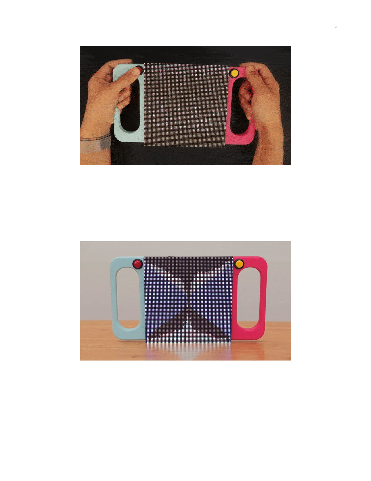
Overview
Simulated LED Sand Physics!
These LEDs interact with motion and looks like they’re affect by gravity. An Adafruit LED matrix displays
the LEDs as little grains of sand which are driven by sampling an accelerometer with Raspberry Pi Zero!
The 3D Printed handles make it easy to hold the 64x64 LED Matrix and the two buttons make it easy to
switch modes or reset simulations!
The code, written by Phillip Burgess (https://adafru.it/iPc), simulates physics by calculating collisions and
terminal velocity.
© Adafruit Industries https://learn.adafruit.com/matrix-led-sand Page 3 of 19
Page 4

Prerequisite Guides
I suggest walking through the following guides to get a better
understanding of the electronics.
Adafruit LIS3DH Triple-Axis
Accelerometer (https://adafru.it/AJo)
RGB Matrix Bonnet for RaspberryPi (https://adafru.it/AJp)
14 x M2.5x5mm Screws
M2.5x5mm Screws
4 x M3x5mm Screws
M3x5mm Screws
WARNING - The hole spacing on the 64x64 2.5mm pitch matrix (PID 3649) has changed. Currently,
the 3D parts DO NOT match this new spacing.
Your browser does not support the video tag.
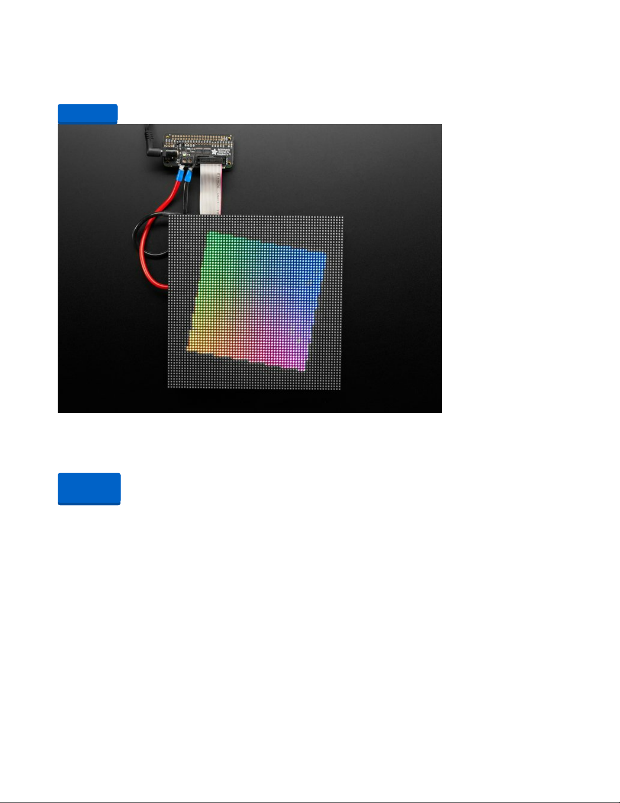
64x64 RGB LED Matrix - 2.5mm Pitch
© Adafruit Industries https://learn.adafruit.com/matrix-led-sand Page 4 of 19
Page 5
Winter time can be rough in the city. The sky is gray. The weather is unpredictable. So slough off those
seasonal blues with some Times Square razzle dazzle from this...
$54.95
In Stock
Adafruit RGB Matrix Bonnet for Raspberry Pi
You can now create a dazzling display with your Raspberry Pi with the Adafruit RGB Matrix Bonnet. These
boards plug into your Pi and makes it super...
Out of Stock
Add to Cart
Out of
Stock
© Adafruit Industries https://learn.adafruit.com/matrix-led-sand Page 5 of 19
Page 6
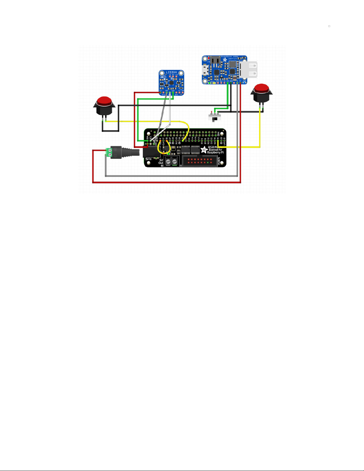
Circuit Diagram
Take a moment to review the components in the circuit diagram. This illustration is meant for referencing
wired connections - The length of wire, position and size of components are not exact.
The Slide switch will connect to the PowerBoost1000C board on the GND and the EN pin
PowerBoost 5v and G connects to the Bonnet via the 2.1mm Male DC adapter and will both need to be
150mm long.
RGB Matrix Bonnet connects to the Raspberry Pi Zero.
LIS3DH connects to the Bonnet and will need to be 80mm long for 3V, GND, SDA and SCL connections.
The Reset Button connects to pin 19 and will need to be 110mm long. Ground will need to be 95mm long.
Mode Button connects to pin 25 on the Bonnet and will need to be 130mm long. Ground will need to be
160mm long.
© Adafruit Industries https://learn.adafruit.com/matrix-led-sand Page 6 of 19
Page 7

Code
https://adafru.it/AJq
First make sure you've loaded the latest Raspbian Lite operating system on your Raspberry Pi. You can
find the OS image download here (https://adafru.it/dpb), instructions for burning to an SD card image
here (https://adafru.it/evK), and a convenient guide here (https://adafru.it/jd1) that explains how to load an
operating system.
Make sure your Raspberry Pi is connected to the internet, either with a wired connection to its ethernet
port, or by setting up wireless access to a WiFi network. Check out the guide on network
setup (https://adafru.it/jd2) for more details on using wireless and WiFi networks with the Pi.
Once your Raspberry Pi is powered up and connected to a network you can follow the steps below to
install the video looper software.
If you're familiar with connecting to the Raspberry Pi over SSH (https://adafru.it/jsE) you can use an SSH
terminal application to connect and skip down to the install commands section below (https://adafru.it/uRC).
If you aren't familiar with SSH you can use the Adafruit Pi Finder tool (https://adafru.it/enj) to find your
Raspberry Pi and open a terminal to run the installation. I'll show installation steps using the Pi Finder tool
below.
Note with the latest versions of Raspbian (Jessie full & lite since ~February 2017) they disable SSH by
default! Read below to see how to enable SSH so you can access the Pi with tools like Pi Finder.
Install Matrix Driver
OK now you are ready to install the drive for the LED matrix. We have a script that downloads the code and
any prerequisite software. It works with the current Raspbian “Stretch” operating system (either the Lite or
Desktop version). Walk through the options it presents and select the ones that pertain to your setup. If you
get stuck, we have a more details in the Bonnet Matrix guide (https://adafru.it/Bma).
curl https://raw.githubusercontent.com/adafruit/Raspberry-Pi-Installer-Scripts/master/rgb-matrix.sh >rgb-matrix.s
h
sudo bash rgb-matrix.sh
The script will confirm your selections and offer one more chance to cancel without changes.
There’s a lot of software to update, download and install, so it may take up to 15 minutes or so to complete.
Afterward, you’ll be asked whether you want to reboot the system.
Install Git and Clone
Once you have enabled SSH and connected to the Pi via a separate computer over WiFi, you can install
the proper tools to install the software. First, let's get the git command so we can clone the library repo.
Then, we'll install the library and copy code from the repo to the home directory of the Pi.
sudo apt-get install -y git
git clone https://github.com/adafruit/Adafruit_PixelDust.git
https://adafru.it/AJq
© Adafruit Industries https://learn.adafruit.com/matrix-led-sand Page 7 of 19
Page 8

Enable I2C via raspi-config
In order to read the accelerometer, I2C must be enabled via the raspi-config interface. Follow the guide
below for a step by step guide. If your familiar with this, use sudo raspi-config and enable I2C through the
“Interfacing Options.”
https://adafru.it/dEO
Make PixelDust
In order to compile the Adafruit PixelDust library to the Pi, we'll need to execute a make command.
cd Adafruit_PixelDust/raspberry_pi
make
Running the Code
OK now it's time to run the demo! Execute the command below and use the two buttons to change demos
and reset the simulation. You'll need to be in the right directory to run the python script.
cd Adafruit_PixelDust/raspberry_pi/
sudo python buttons.py
Press Control+C to stop the program and get back to the command line.
Adjusting Brightness
By default the LED brightness is set to 100%…this might be a bit much both on the eyes and the battery. We
can tone it down by editing the Python script…
nano buttons.py
Look for this line near the top of the code (around line 15):
FLAGS = ["--led-rgb-sequence=rbg", "--led-brightness=100"]
That “100” is the brightness, expressed as a percentage from 1 to 100. Quite often running around 1/3
brightness (33) looks perfectly good. For photography and video you may want even less, perhaps 10
percent. Save changes to the file, exit and try running again with “sudo python buttons.py”
Automatic Startup
We can configure the system to start the demo automatically after booting, so you don’t need a keyboard
and screen to get it started every time…
sudo nano /etc/rc.local
Just BEFORE the final “exit 0” line, insert the following two lines:
cd /home/pi/Adafruit_PixelDust/raspberry_pi
python buttons.py &
(If you’ve installed the code in a different location, adjust the “cd” command to match.)
Save changes to the file, exit and reboot.
https://adafru.it/dEO
© Adafruit Industries https://learn.adafruit.com/matrix-led-sand Page 8 of 19
Page 9

It may take 30 second to a minute before the software starts. This is normal…booting a Linux system is a lot
of work and our code is the last thing to run.
Safely Shutdown setup
Turning the switch off before properly shutting down the Pi can cause the SD card to corrupt so we
suggest safely shutting down the Pi before turning off the PowerBoost. We have a dedicate guide for
enabling Read-Only mode which will allow you to quickly turn off the Pi without risking corrupting the SD
card. Check it out here: https://learn.adafruit.com/read-only-raspberry-pi (https://adafru.it/AJr)
https://adafru.it/AJr
Customization Options
The Python script (Adafruit_PixelDust/raspberry_pi/buttons.py) uses two buttons (currently on GPIO 19 and
25) to cycle between demos or reset the current one. Near the top of that file you'll see settings for the
GPIO pin numbers and LED brightness. You can edit and save the script using nano buttons.py so you
won't not have to type changes every single time.
https://adafru.it/AJr
© Adafruit Industries https://learn.adafruit.com/matrix-led-sand Page 9 of 19
Page 10

3D Printing
The 3D printed parts are fairly easy to make with most common home desktop 3D printers that are on the
market.
And if you don’t have access a 3D printer, you can order our parts by visiting our Thingiverse page and
have someone local 3D print the parts and ship them to you.
Our LED Matrix hole spacing has been updated causing the original STL files not work. An updated
set of STLs are available thanks to @KDLaun. https://www.thingiverse.com/thing:4805155
https://adafru.it/AJs
https://adafru.it/AJt
https://adafru.it/AJu
https://adafru.it/AJy
https://adafru.it/AJs
https://adafru.it/AJt
https://adafru.it/AJu
https://adafru.it/AJy
© Adafruit Industries https://learn.adafruit.com/matrix-led-sand Page 10 of 19
Page 11

Slice Settings
Download the STL file and import it into your 3D printing slicing
software. You'll need to adjust your settings accordingly if
you're using material different than PLA.
230C Extruder Temp
No heated bed (65C for heated)
1.0 Extrusion Multiplier
.8mm Nozzle
0.7 Extrusion Width
.2mm Layer Height
30% infill
30% Supports
skirt
60mm/s | 120mm travel speed
Mirror
Use the mirror function inside your slicing software to print the
opposite handle
© Adafruit Industries https://learn.adafruit.com/matrix-led-sand Page 11 of 19
Page 12

Assemble
Prep Bonnet
First we'll need to add a jumper to connect two pins and then
bridge two pads to enable the RGB Matrix Bonnet to work with
the 64x64 LED Matrix.
Jumper
We'll start by measuring a wire 30mm long. Tin and solder pin
4 to pin 18. Carefully bend the wire and move it away from the
headers on the Bonnet.
Bridge Pad
Next we need to turn the Matrix Bonnet over and locate the
three solder pads. Tin the middle pad "E" and the "8" pad.
Now heat up one of the pads and drag solder over to the next
pad to bridge the two connections.
Solder LIS3DH
The accelerometer is solder to the Bonnet. Measure four wires
80mm long to connect 5v, GND, SDA, and SLC on the Bonnet
and LIS3DH .
We used heat shrink to keep the wires organized.
© Adafruit Industries https://learn.adafruit.com/matrix-led-sand Page 12 of 19
Page 13

PowerBoost
Now we'll need to measure wires for power and ground to
connect the Pi and Bonnet. Cut wires 150mm long so it can
reach the barrel on the Bonnet.
Slide Switch
To power the circuit on and off, we'll add a slide switch on the
GND and EN pin on the PowerBoost.
DC Plug
Power and ground connect to the DC plug by tightening the
terminal screws.
Board Frame
With all of the boards soldered we can move on to mounting
them to the LED-boards part.
Use M2.5mmx5mm long screws to mount the boards to each
standoff on the part.
© Adafruit Industries https://learn.adafruit.com/matrix-led-sand Page 13 of 19
Page 14

Matrix Cables
Now we can move on to the LED Matrix! Connect the red
ribbon cable and the power and ground wire plug as shown on
the picture.
Matrix Handles
To attach the handles, we'll use the M3 thumb screws included
with the LED Matrix. Align the handles so the button holes both
align with the Matrix.
Secure by inserting the thumb screws into the counter sink
holes and tighten. You can use pliers to ensure the handles
are securely attached.
Attach boards frame
Position the boards to align with the mounting holes on the
LED Matrix. Use M3x5mm long screws to secure the boards
onto the LED Matrix.
Note that the PowerBoost will cover one of the mounting
holes, so we'll need to secure that one screw on the Matrix
frame and then fasten the PowerBoost back on.
© Adafruit Industries https://learn.adafruit.com/matrix-led-sand Page 14 of 19
Page 15

Battery frame
Mount the 6600mAh battery to the LED-bat part. Align it so the
cable is positioned on the inside of the battery frame as shown
in the picture.
Turn the two over and use a zip tie or twisty ties to secure the
battery to the frame. Pass the ties through the two slits on the
battery frame to tightly secure the battery to the frame.
Mount Battery frame
Use M3x5mm long screws to secure the battery frame to the
LED Matrix. Align the mount as shown and fasten each screw
to attach the part to the matrix.
© Adafruit Industries https://learn.adafruit.com/matrix-led-sand Page 15 of 19
Page 16

Buttons
To easily connect and disconnect the buttons, we'll use quick
connects. First start by measuring wires for the reset button.
The Reset Button will connect to Pin 19 on the Bonnet and will
need to be 110mm long. The GND wire will need to be 95mm
long.
The Mode button will connect to Pin 25 on the Bonnet, and
will need to 130mm long. GND will need to be 160mm long.
Mount buttons
The two buttons mount inside the cutouts on the handles.
Push each button through to snap fit them on to the handles.
Solder Buttons
Next we'll solder the buttons to the GPIOs on the Bonnet. Tin
and solder connects for Pin 19 and Pin 25.
Ground
To make it easy, we'll solder the two ground connections to
the slide switch leg connected to GND on the PowerBoost.
© Adafruit Industries https://learn.adafruit.com/matrix-led-sand Page 16 of 19
Page 17

Thread Button wires
Finally we can thread our button wires through the LED frame
and connect them to each button.
Connect Battery
All thats left is to plug the battery into the JST connection on
the PowerBoost and flip on the switch!
© Adafruit Industries https://learn.adafruit.com/matrix-led-sand Page 17 of 19
Page 18

© Adafruit Industries https://learn.adafruit.com/matrix-led-sand Page 18 of 19
Page 19

© Adafruit Industries Last Updated: 2021-03-25 12:47:35 PM EDT Page 19 of 19
 Loading...