


Adafruit Qualia ESP32-S3 for RGB-666
Displays
Created by Melissa LeBlanc-Williams
https://learn.adafruit.com/adafruit-qualia-esp32-s3-for-rgb666-displays
Last updated on 2023-10-20 10:53:17 AM EDT
©Adafruit Industries Page 1 of 199

Table of Contents
Overview
Pinouts
• Microcontroller and WiFi
• 40-Pin Display Connector
• IO Expander
• Stemma QT Connector
• Reset and Boot0 Pins
• Debug Pin
• SPI Pins
• Analog Connector/Pins
• Buttons
• Backlight Jumpers
• IO Expander Address Jumpers
• Parallel Interface Jumpers
CircuitPython
• CircuitPython Quickstart
The CIRCUITPY Drive
• Boards Without CIRCUITPY
CircuitPython Pins and Modules
• CircuitPython Pins
• import board
• I2C, SPI, and UART
• What Are All the Available Names?
• Microcontroller Pin Names
• CircuitPython Built-In Modules
7
11
16
19
20
Installing the Mu Editor
• Download and Install Mu
• Starting Up Mu
• Using Mu
Creating and Editing Code
• Creating Code
• Editing Code
• Back to Editing Code...
• Naming Your Program File
Exploring Your First CircuitPython Program
• Imports & Libraries
• Setting Up The LED
• Loop-de-loops
• What Happens When My Code Finishes Running?
• What if I Don't Have the Loop?
Connecting to the Serial Console
• Are you using Mu?
• Serial Console Issues or Delays on Linux
26
28
33
36
©Adafruit Industries Page 2 of 199

• Setting Permissions on Linux
• Using Something Else?
Interacting with the Serial Console
The REPL
• Entering the REPL
• Interacting with the REPL
• Returning to the Serial Console
CircuitPython Libraries
• The Adafruit Learn Guide Project Bundle
• The Adafruit CircuitPython Library Bundle
• Downloading the Adafruit CircuitPython Library Bundle
• The CircuitPython Community Library Bundle
• Downloading the CircuitPython Community Library Bundle
• Understanding the Bundle
• Example Files
• Copying Libraries to Your Board
• Understanding Which Libraries to Install
• Example: ImportError Due to Missing Library
• Library Install on Non-Express Boards
• Updating CircuitPython Libraries and Examples
• CircUp CLI Tool
CircuitPython Documentation
• CircuitPython Core Documentation
• CircuitPython Library Documentation
39
42
46
57
Recommended Editors
• Recommended editors
• Recommended only with particular settings or add-ons
• Editors that are NOT recommended
Advanced Serial Console on Windows
• Windows 7 and 8.1
• What's the COM?
• Install Putty
Advanced Serial Console on Mac
• What's the Port?
• Connect with screen
Advanced Serial Console on Linux
• What's the Port?
• Connect with screen
• Permissions on Linux
Frequently Asked Questions
• Using Older Versions
• Python Arithmetic
• Wireless Connectivity
• Asyncio and Interrupts
• Status RGB LED
• Memory Issues
64
65
69
71
75
©Adafruit Industries Page 3 of 199

• Unsupported Hardware
Troubleshooting
• Always Run the Latest Version of CircuitPython and Libraries
• I have to continue using CircuitPython 7.x or earlier. Where can I find compatible libraries?
• Bootloader (boardnameBOOT) Drive Not Present
• Windows Explorer Locks Up When Accessing boardnameBOOT Drive
• Copying UF2 to boardnameBOOT Drive Hangs at 0% Copied
• CIRCUITPY Drive Does Not Appear or Disappears Quickly
• Device Errors or Problems on Windows
• Serial Console in Mu Not Displaying Anything
• code.py Restarts Constantly
• CircuitPython RGB Status Light
• CircuitPython 7.0.0 and Later
• CircuitPython 6.3.0 and earlier
• Serial console showing ValueError: Incompatible .mpy file
• CIRCUITPY Drive Issues
• Safe Mode
• To erase CIRCUITPY: storage.erase_filesystem()
• Erase CIRCUITPY Without Access to the REPL
• For the specific boards listed below:
• For SAMD21 non-Express boards that have a UF2 bootloader:
• For SAMD21 non-Express boards that do not have a UF2 bootloader:
• Running Out of File Space on SAMD21 Non-Express Boards
• Delete something!
• Use tabs
• On MacOS?
• Prevent & Remove MacOS Hidden Files
• Copy Files on MacOS Without Creating Hidden Files
• Other MacOS Space-Saving Tips
• Device Locked Up or Boot Looping
80
Welcome to the Community!
• Adafruit Discord
• CircuitPython.org
• Adafruit GitHub
• Adafruit Forums
• Read the Docs
Create Your settings.toml File
• CircuitPython settings.toml File
• settings.toml File Tips
• Accessing Your settings.toml Information in code.py
CircuitPython Internet Test
• The settings.toml File
Converting Arduino_GFX init strings to CircuitPython
• Using Arduino_GFX Init Codes
• Using Init Code Files
• Script Output
Determining Timings
• Using a Data Sheet
• Fill in the Settings
• Experimenting with Settings
98
107
110
115
119
©Adafruit Industries Page 4 of 199

• Testing your Settings with CircuitPython
CircuitPython Display Setup
• Example TFT_PINS
• Example TFT_TIMINGS
• I/O Expander
• Display Initialization Code
• Sending Initialization Code via I2C IO Expander
• I2C Bus Speed
• Constructing the framebuffer and the display
• Dot clocks
CircuitPython Touch Display Usage
• Determining the I2C Address
• Initializing the Touch Controller
• Reading from the Touch Controller
• Example
Qualia S3 RGB-666 with TL021WVC02 2.1" 480x480 Round Display
• Initialization Codes
• Timings
• Example
Qualia S3 RGB-666 with TL034WVS05 3.4" 480x480 Square Display
• Initialization Codes
• Timings
• Example
123
135
139
142
Qualia S3 RGB-666 with TL040HDS20 4.0" 720x720 Square Display
• Initialization Codes
• Timings
• Example
Qualia S3 RGB-666 with TL032FWV01 3.2" 320x820 Bar Display
• Initialization Codes
• Timings
• Example
Arduino IDE Setup
Using with Arduino IDE
• Blink
• Select ESP32-S2/S3 Board in Arduino IDE
• Launch ESP32-S2/S3 ROM Bootloader
• Load Blink Sketch
WiFi Test
• WiFi Connection Test
• Secure Connection Example
• JSON Parsing Demo
146
149
153
156
160
Usage with Adafruit IO
• Install Libraries
• Adafruit IO Setup
• Code Usage
©Adafruit Industries Page 5 of 199
171

Arduino Rainbow Demo
179
Arduino Touch Display Usage
• Determining the I2C Address
• Initializing the Touch Controller
• Reading from the Touch Controller
• Example
Install UF2 Bootloader
Factory Reset
• Factory Reset Firmware UF2
• Factory Reset and Bootloader Repair
• Download .bin and Enter Bootloader
• Step 1. Download the factory-reset-and-bootloader.bin file
• Step 2. Enter ROM bootloader mode
• The WebSerial ESPTool Method
• Connect
• Erase the Contents
• Program the ESP32-S2/S3
• The esptool Method (for advanced users)
• Install ESPTool.py
• Test the Installation
• Connect
• Erase the Flash
• Installing the Bootloader
• Reset the board
• Older Versions of Chrome
• TheFlash an Arduino Sketch Method
• Arduino IDE Setup
• Load the Blink Sketch
182
184
185
Downloads
• Schematic
• Fab Print
198
©Adafruit Industries Page 6 of 199

Overview
There are things everyone loves: ice cream, kittens, and honkin' large TFT LCD
screens. We're no strangers to small TFT's -from our itsy 1.14" color display()that
graces many-a-TFT-Feather toour fancy 3.5" 320x480() breakout screen. But most
people who dabble or engineer with microcontrollers know that you sort of 'top out' at
320x480 - that's the largest resolution you can use with every day SPI or 8-bit 8080
interfaces. After that, you're in TTL-interfaceTFT land, where displays no longer have
an internal memory buffer and instead the controller has to continuously write
scanline data over a 16, 18 or 24 pin interface.
©Adafruit Industries Page 7 of 199
RGB TTL interface TFT displays can get big: they start out at around4.3" diagonal
480x272, and can get to 800x480, 800x600 or even 720x720. For displays that big,
you need a lot of video RAM (800x480 at 24 bit color is just over 1MB), plenty of spare
GPIO to dedicate, and a peripheral that will DMA the video RAM out to the display
continuously. This is a setup familiar to people working with hefty microcontrollers or
microcomputers, the sort of device that run cell phones, or your car's GPS navigation
screen. But until now, nearly impossible to use on low cost microcontrollers.
The ESP32-S3 is the first low-cost microcontroller that has a built in peripheral that
can drive TTL displays, and it can come with enough PSRAM to buffer those large
images. For example, on theAdafruit Qualia ESP32-S3 for TTL RGB-666 Displays, we
use a S3 module with 16 MB of Flash and 8 MB of octal PSRAM. Using the built in RGB
display peripheral you can display graphics, images, animations or even video
(cinepak, natch!) with near-instantaneous updates since the whole screen gets
updated about 30 frames per second (FPS).
This dev board is designed to make it easy for you to explore displays that use the
'secondary standard' 40-pin RGB-666 connector. This pin order is most commonly
seen on square, round and bar displays.You'll want to compare the display you're
using to this datasheet(), and if it matches, you'll probably be good! One nice thing
about this connector ordering is that it also includes pins for capacitive touch overlay,
and we wire those up to the ESP32-S3's I2C port so you can also have touch control
with your display.
©Adafruit Industries Page 8 of 199

Don't forget! This is just the development board, a display is not included.Use any
RGB-666 pinout display with or without a touch overlay. Note that you will need to
program in the driver initialization code, dimensions, and pulse widths in your
programming language. Here are some known-working displays that you can use in
Arduino and CircuitPython:
2.1" 480x480 Round with Capacitive Touch()
•
2.1" 480x480 Round without Touch()
•
4" 720x720 Square with Capacitive Touch()
•
4" 720x720 Round without Touch()
•
4.6" 960x320 Rectangular Bar()
•
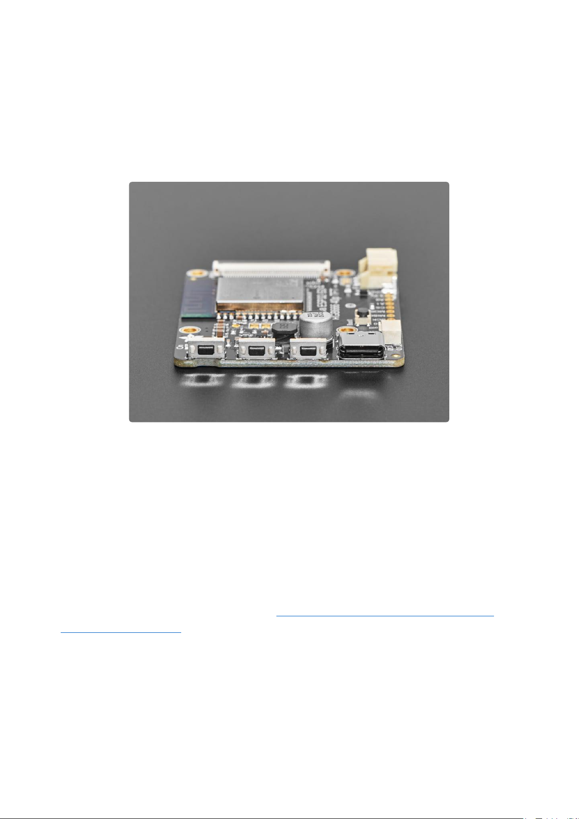
On the Qualia board we have the S3 modules, with 16 pins connected to the TFT for
5-6-5 RGB color, plus HSync, VSync, Data Enable and Pixel Clock. There's a constant
current backlight control circuit using theTPS61169()which can get up to 30V
forward voltage and can be configured for 25mA-200mA in 25mA increments (default
is 25mA). Power and programming is provided over a USB C connector, wired to the
S3's native USB port. For debugging, the hardware UART TX pin is available as well.
©Adafruit Industries Page 9 of 199

Since almost every GPIO is used, and almost allRGB-666 displays need to be
initialized over SPI, we put aPCA9554()I/O expander on the shared I2C bus. Arduino
or CircuitPython can be instructed on how to use the expander to reset and init the
display you have if necessary. The remaining expander pins are connected to two
right-angle buttons, and the display backlight.
The expander is what lets us have a full 4-pin SPI port and two more analog GPIO pins
-enough to wire up an MMC in 1-wire SDIO mode along with an I2S amplifier to make
an A/V playback demo(). Maybe we can even eat ice cream while watching kitten
vids!There is also the shared I2C port, we provide a Stemma QT / Qwiic port for easy
addition of any sensor or device you like.
©Adafruit Industries Page 10 of 199

Pinouts
Microcontroller and WiFi
The main processor chip is
theEspressifESP32-S3with 3.3v logic/
power. It has 16MBof Flash and 8MBof
RAM.
The ESP32-S3 comes with WiFi and
Bluetooth LEbaked right in, though
CircuitPython only supports WiFi at this
time, not BLE on the S3 chip
40-Pin Display Connector
Not all 40-pin displays have the power pins in the same place. Hooking up a non
RGB666 display with the Qualia S3 risks damaging the display.
©Adafruit Industries Page 11 of 199

IO Expander
There is a 40-pin display connector to
connect your display. Displays should be
connected with the pins of the cable down
towards the board and the colored side
facing you.
The Qualia S3 includes aPCA9554 IO
Expander. The IO Expander is connected
via the I2C bus. The main purpose of the
expander is to add additional pins to
communicate with the display.
Stemma QT Connector
The default address of the IO expander is
0x3F, but it can be changed by soldering
jumpers on the reverse side in case it
interferes with another I2C device.
There is a 4-pinStemma QTconnectoron
the left. The I2C has pullups to 3.3V power.
In CircuitPython, you can use the STEMMA
connector
with board.SCL and board.SDA ,
or board.STEMMA_I2C() .
©Adafruit Industries Page 12 of 199

Reset and Boot0 Pins
Debug Pin
Resetis the Reset pin. Tie to ground to
manually reset the ESP32-S3.
TyingBoot0to ground while resetting will
place the ESP32-S3 in ROM bootloader
mode.
If you'd like to do lower level debugging,
we have the ESP32-S3's TXD0 debug pin
exposed as TX0 to view messages.
To read, you would connect a Serial UART
cable Receive connection here and the
cable ground connection to the GND pin.
©Adafruit Industries Page 13 of 199
SPI Pins
The SPI pins of the ESP32-S3 are exposed
for communication with other SPI
hardware.
Each of these pins can alternatively be
used for digital I/O:
SCK is connected to board.TFT_SCK
Arduino 5 .
MISO is connected to board.TFT_MISO
Arduino 6 .
MOSI is connected to board.TFT_MOSI
Arduino 7 .
CS is connected to board.TFT_CS
Arduino 15 and includes a 10K Pull-up
resistor.
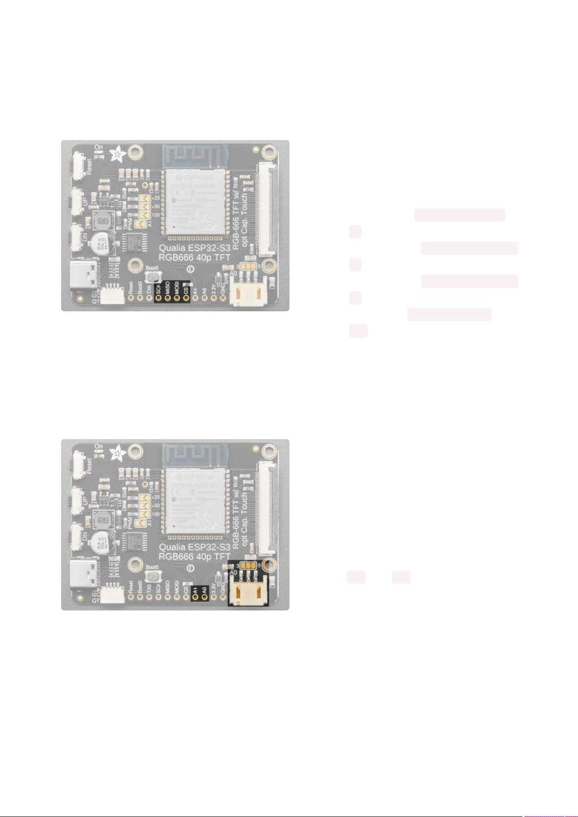
Analog Connector/Pins
On the bottom side towards the right,
there is a connector labeledA0. This is
a3-pin JST analog connectorfor sensors,
NeoPixels, or analog output or input.
For the JST connected, there is a jumper
above that can be cut and soldered to use
3V instead of 5V.
Along the bottom there are also pins
labeled A0 and A1 .
Each of these pins can be used for analog
inputs or digital I/O.
©Adafruit Industries Page 14 of 199

Buttons
There are three buttons along the left side
of the Qualia S3.
The Reset buttonis located in the top
position. Click it once to re-start your
firmware. Click it again after about a half
second to enter bootloader mode.
The UPbutton is located in the middle and
is connected to the IO expander
The DN button, or Down button, is located
on the bottom and is connected to the IO
expander.
The expander implements a light pullup for
each of the buttons and pressing either of
them pulls the input low.
Backlight Jumpers
The Boot0 button is located between the
up button and the Microcontroller. Hold it
while pressing reset to enter ROM
Bootloader mode.
Soldering the bottom PWM jumper allows
using Pin A1 to control the backlight of
the display.
By default, 25mA is provided to the
backlight, but additional amperage can be
set by soldering the top jumpers to
provide up to 200mA if needed.
©Adafruit Industries Page 15 of 199
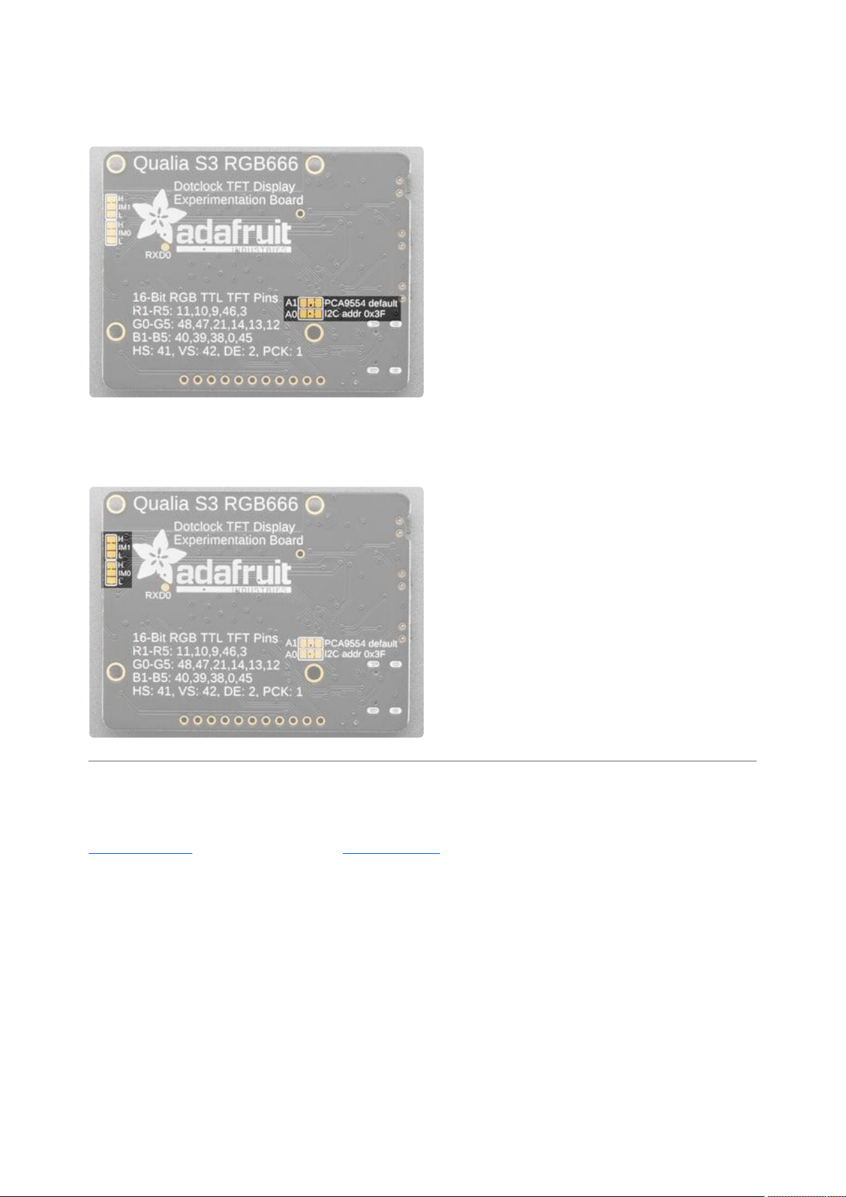
IO Expander Address Jumpers
Parallel Interface Jumpers
On the reverse, are a couple of solderable
jumpers to change the I2C address of the
IO Expander. By default, both jumpers are
set to high, providing a default address of
0x3F. However, it can be set between
0x3B-0x3F.
The IM0 and IM1 jumpers are for selecting
the mode of the parallel interface for the
display. The default selection should work
for most displays.
CircuitPython
CircuitPython() is a derivative of MicroPython() designed to simplify experimentation
and education on low-cost microcontrollers. It makes it easier than ever to get
prototyping by requiring no upfront desktop software downloads. Simply copy and
edit files on the CIRCUITPY drive to iterate.
CircuitPython Quickstart
Follow this step-by-step to quickly get CircuitPython running on your board.
©Adafruit Industries Page 16 of 199

This microcontroller requires the latest unstable (development)release of
CircuitPython. Click below to visit the downloads page on circuitpython.org for your
board. Then, Browse S3 under Absolute Newest.
Download the latest version of
CircuitPython for this board via
circuitpython.org
Click the link above to download the latest
CircuitPython UF2 file.
Save it wherever is convenient for you.
The Qualia S3 does not have a RGB status LED
Plug your board into your computer, using a known-good data-sync cable, directly, or
via an adapter if needed.
©Adafruit Industries Page 17 of 199

Double-click the reset button (highlighted in red above), and you will see the RGB
status LED(s) turn green (highlighted in green above). If you see red, try another port,
or if you're using an adapter or hub, try without the hub, or different adapter or hub.
This board does not have a Neopixel, so you will need to just double tap the
reset button.
For this board, tap reset and wait about a half a second and then tap reset again.
Some boards may not have a UF2 bootloader installed. If double-clicking does
not work, follow the instructions on the "Install UF2 Bootloader" page in this
guide.
If double-clicking doesn't work the first time, try again. Sometimes it can take a few
tries to get the rhythm right!
A lot of people end up using charge-only USB cables and it is very frustrating! Make
sure you have a USB cable you know is good for data sync.
You will see a new disk drive appear called
TFT_S3BOOT.
Drag the adafruit_circuitpython_etc.uf2 file
to TFT_S3BOOT.
©Adafruit Industries Page 18 of 199

The BOOT drive will disappear and a new
disk drive called CIRCUITPY will appear.
That's it!
The CIRCUITPY Drive
When CircuitPython finishes installing, or you plug a CircuitPython board into your
computer with CircuitPython already installed, the board shows up on your computer
as a USB drive called CIRCUITPY.
The CIRCUITPY drive is where your code and the necessary libraries and files will live.
You can edit your code directly on this drive and when you save, it will run
automatically. When you create and edit code, you'll save your code in a code.py file
located on the CIRCUITPY drive.If you're following along with a Learn guide, you can
paste the contents of the tutorial example into code.py on the CIRCUITPY drive and
save it to run the example.
With a fresh CircuitPython install, on your CIRCUITPY drive, you'll find a code.py file
containing print("Hello World!") and an empty lib folder. If your CIRCUITPY
drive does not contain a code.py file, you can easily create one and save it to the
drive. CircuitPython looks for code.py and executes the code within the file
automatically when the board starts up or resets. Following a change to the contents
of CIRCUITPY, such as making a change to the code.py file, the board will reset, and
the code will be run. You do not need to manually run the code. This is what makes it
so easy to get started with your project and update your code!
Note that all changes to the contents of CIRCUITPY, such as saving a new file,
renaming a current file, or deleting an existing file will trigger a reset of the board.
©Adafruit Industries Page 19 of 199

Boards Without CIRCUITPY
CircuitPython is available for some microcontrollers that do not support native USB.
Those boards cannot present a CIRCUITPY drive. This includes boards using ESP32
or ESP32-C3 microcontrollers.
On these boards, there are alternative ways to transfer and edit files. You can use the
Thonny editor(), which uses hidden commands sent to the REPL to read and write
files. Or you can use the CircuitPython web workflow, introduced in Circuitpython 8.
The web workflow provides browser-based WiFi access to the CircuitPython
filesystem. These guides will help you with the web workflow:
CircuitPython on ESP32 Quick Start()
•
CircuitPython Web Workflow Code Editor Quick Start()
•
CircuitPython Pins and Modules
CircuitPython is designed to run on microcontrollers and allows you to interface with
all kinds of sensors, inputs and other hardware peripherals. There are tons of guides
showing how to wire up a circuit, and use CircuitPython to, for example, read data
from a sensor, or detect a button press. Most CircuitPython code includes hardware
setup which requires various modules, such as board or digitalio . You import
these modules and then use them in your code. How does CircuitPython know to look
for hardware in the specific place you connected it, and where do these modules
come from?
This page explains both. You'll learn how CircuitPython finds the pins on your
microcontroller board, including how to find the available pins for your board and
what each pin is named. You'll also learn about the modules built into CircuitPython,
including how to find all the modules available for your board.
©Adafruit Industries Page 20 of 199

CircuitPython Pins
When using hardware peripherals with a CircuitPython compatible microcontroller,
you'll almost certainly be utilising pins. This section will cover how to access your
board's pins using CircuitPython, how to discover what pins and board-specific
objects are available in CircuitPython for your board, how to use the board-specific
objects, and how to determine all available pin names for a given pin on your board.
import board
When you're using any kind of hardware peripherals wired up to your microcontroller
board, the import list in your code will include import board . The board module is
built into CircuitPython, and is used to provide access to a series of board-specific
objects, including pins. Take a look at your microcontroller board. You'll notice that
next to the pins are pin labels. You can always access a pin by its pin label. However,
there are almost always multiple names for a given pin.
To see all the available board-specific objects and pins for your board, enter the REPL
( >>> ) and run the following commands:
import board
dir(board)
Here is the output for the QT Py SAMD21. You may have a different board, and this list
will vary, based on the board.
The following pins have labels on the physical QT Py SAMD21 board: A0, A1, A2, A3,
SDA, SCL, TX, RX, SCK, MISO, and MOSI. You see that there are many more entries
available in board than the labels on the QT Py.
You can use the pin names on the physical board, regardless of whether they seem to
be specific to a certain protocol.
For example, you do not have to use the SDA pin for I2C - you can use it for a button
or LED.
©Adafruit Industries Page 21 of 199

On the flip side, there may be multiple names for one pin. For example, on the QT Py
SAMD21, pin A0 is labeled on the physical board silkscreen, but it is available in
CircuitPython as both A0 and D0 . For more information on finding all the names for a
given pin, see the What Are All the Available Pin Names?() section below.
The results of dir(board) for CircuitPython compatible boards will look similar to
the results for the QT Py SAMD21 in terms of the pin names, e.g. A0, D0, etc.
However, some boards, for example, the Metro ESP32-S2, have different styled pin
names. Here is the output for the Metro ESP32-S2.
Note that most of the pins are named in an IO# style, such as IO1 and IO2. Those pins
on the physical board are labeled only with a number, so an easy way to know how to
access them in CircuitPython, is to run those commands in the REPL and find the pin
naming scheme.
If your code is failing to run because it can't find a pin name you provided, verify
that you have the proper pin name by running these commands in the REPL.
I2C, SPI, and UART
You'll also see there are often (but not always!) three special board-specific objects
included: I2C , SPI , and UART - each one is for the default pin-set used for each of
the three common protocol busses they are named for. These are called singletons.
What's a singleton? When you create an object in CircuitPython, you are instantiating
('creating') it. Instantiating an object means you are creating an instance of the object
with the unique values that are provided, or "passed", to it.
For example, When you instantiate an I2C object using the busio module, it expects
two pins: clock and data, typically SCL and SDA. It often looks like this:
i2c = busio.I2C(board.SCL, board.SDA)
Then, you pass the I2C object to a driver for the hardware you're using. For example,
if you were using the TSL2591 light sensor and its CircuitPython library, the next line
of code would be:
©Adafruit Industries Page 22 of 199

tsl2591 = adafruit_tsl2591.TSL2591(i2c)
However, CircuitPython makes this simpler by including the I2C singleton in the boa
rd module. Instead of the two lines of code above, you simply provide the singleton
as the I2C object. So if you were using the TSL2591 and its CircuitPython library, the
two above lines of code would be replaced with:
tsl2591 = adafruit_tsl2591.TSL2591(board.I2C())
The board.I2C(), board.SPI(), and board.UART() singletons do not exist on all
boards. They exist if there are board markings for the default pins for those
devices.
This eliminates the need for the busio module, and simplifies the code. Behind the
scenes, the board.I2C() object is instantiated when you call it, but not before, and
on subsequent calls, it returns the same object. Basically, it does not create an object
until you need it, and provides the same object every time you need it. You can call
board.I2C() as many times as you like, and it will always return the same object.
The UART/SPI/I2C singletons will use the 'default' bus pins for each board - often
labeled as RX/TX (UART), MOSI/MISO/SCK (SPI), or SDA/SCL (I2C). Check your
board documentation/pinout for the default busses.
What Are All the Available Names?
Many pins on CircuitPython compatible microcontroller boards have multiple names,
however, typically, there's only one name labeled on the physical board. So how do
you find out what the other available pin names are? Simple, with the following script!
Each line printed out to the serial console contains the set of names for a particular
pin.
On a microcontroller board running CircuitPython, first, connect to the serial console.
In the example below, click the Download Project Bundle button below to download
the necessary libraries and the code.py file in a zip file. Extract the contents of the zip
file, open the directory CircuitPython_Essentials/Pin_Map_Script/ and then click on
the directory that matches the version of CircuitPython you're using and copy the
contents of that directory to your CIRCUITPY drive.
Your CIRCUITPY drive should now look similar to the following image:
©Adafruit Industries Page 23 of 199

# SPDX-FileCopyrightText: 2020 anecdata for Adafruit Industries
# SPDX-FileCopyrightText: 2021 Neradoc for Adafruit Industries
# SPDX-FileCopyrightText: 2021-2023 Kattni Rembor for Adafruit Industries
# SPDX-FileCopyrightText: 2023 Dan Halbert for Adafruit Industries
#
# SPDX-License-Identifier: MIT
"""CircuitPython Essentials Pin Map Script"""
import microcontroller
import board
try:
import cyw43 # raspberrypi
except ImportError:
cyw43 = None
board_pins = []
for pin in dir(microcontroller.pin):
if (isinstance(getattr(microcontroller.pin, pin), microcontroller.Pin) or
(cyw43 and isinstance(getattr(microcontroller.pin, pin), cyw43.CywPin))):
pins = []
for alias in dir(board):
if getattr(board, alias) is getattr(microcontroller.pin, pin):
pins.append(f"board.{alias}")
# Add the original GPIO name, in parentheses.
if pins:
# Only include pins that are in board.
pins.append(f"({str(pin)})")
board_pins.append(" ".join(pins))
for pins in sorted(board_pins):
print(pins)
Here is the result when this script is run on QT Py SAMD21:
Each line represents a single pin. Find the line containing the pin name that's labeled
on the physical board, and you'll find the other names available for that pin. For
example, the first pin on the board is labeled A0. The first line in the output is board.
A0 board.D0 (PA02) . This means that you can access pin A0 in CircuitPython using
both board.A0 and board.D0 .
©Adafruit Industries Page 24 of 199

The pins in parentheses are the microcontroller pin names. See the next section for
more info on those.
You'll notice there are two "pins" that aren't labeled on the board but appear in the
list: board.NEOPIXEL and board.NEOPIXEL_POWER . Many boards have several of
these special pins that give you access to built-in board hardware, such as an LED or
an on-board sensor. The QT Py SAMD21 only has one on-board extra piece of
hardware, a NeoPixel LED, so there's only the one available in the list. But you can
also control whether or not power is applied to the NeoPixel, so there's a separate pin
for that.
That's all there is to figuring out the available names for a pin on a compatible
microcontroller board in CircuitPython!
Microcontroller Pin Names
The pin names available to you in the CircuitPython board module are not the same
as the names of the pins on the microcontroller itself. The board pin names are
aliases to the microcontroller pin names. If you look at the datasheet for your
microcontroller, you'll likely find a pinout with a series of pin names, such as "PA18" or
"GPIO5". If you want to get to the actual microcontroller pin name in CircuitPython,
you'll need the microcontroller.pin module. As with board , you can run dir(mi
crocontroller.pin) in the REPL to receive a list of the microcontroller pin names.
CircuitPython Built-In Modules
There is a set of modules used in most CircuitPython programs. One or more of these
modules is always used in projects involving hardware. Often hardware requires
installing a separate library from the Adafruit CircuitPython Bundle. But, if you try to
find board or digitalio in the same bundle, you'll come up lacking. So, where do
these modules come from? They're built into CircuitPython! You can find an
comprehensive list of built-in CircuitPython modules and the technical details of their
functionality from CircuitPython here() and the Python-like modules included here().
However, not every module is available for every board due to size constraints or
hardware limitations. How do you find out what modules are available for your board?
©Adafruit Industries Page 25 of 199

There are two options for this. You can check the support matrix(), and search for
your board by name. Or, you can use the REPL.
Plug in your board, connect to the serial console and enter the REPL. Type the
following command.
help("modules")
That's it! You now know two ways to find all of the modules built into CircuitPython for
your compatible microcontroller board.
Installing the Mu Editor
Mu is a simple code editor that works with the Adafruit CircuitPython boards. It's
written in Python and works on Windows, MacOS, Linux and Raspberry Pi. The serial
console is built right in so you get immediate feedback from your board's serial
output!
Mu is our recommended editor - please use it (unless you are an experienced
coder with a favorite editor already!).
©Adafruit Industries Page 26 of 199

Download and Install Mu
Download Mu fromhttps://codewith.mu().
Click theDownload link for downloads and
installation instructions.
Click Start Hereto find a wealth of other
information, including extensive tutorials
and and how-to's.
Windows users: due to the nature of MSI installers, please remove old versions of
Mu before installing the latest version.
Starting Up Mu
The first time you start Mu, you will be
prompted to select your 'mode' - you can
always change your mind later. For now
please select CircuitPython!
The current mode is displayed in the lower
right corner of the window, next to the
"gear" icon. If the mode says "Microbit" or
something else, click the Mode button in
the upper left, and then choose
"CircuitPython" in the dialog box that
appears.
©Adafruit Industries Page 27 of 199

Mu attempts to auto-detect your board on
startup, so if you do not have a
CircuitPython board plugged in with a
CIRCUITPY drive available, Mu will inform
you where it will store any code you save
until you plug in a board.
To avoid this warning, plug in a board and
ensure that the CIRCUITPY drive is
mounted before starting Mu.
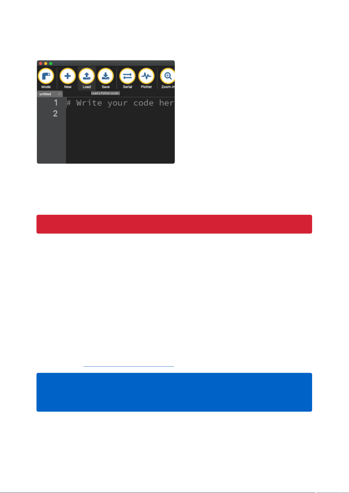
Using Mu
You can now explore Mu! The three main sections of the window are labeled below;
the button bar, the text editor, and the serial console / REPL.
Now you're ready to code! Let's keep going...
Creating and Editing Code
One of the best things about CircuitPython is how simple it is to get code up and
running. This section covers how to create and edit your first CircuitPython program.
To create and edit code, all you'll need is an editor. There are many options. Adafruit
strongly recommends using Mu! It's designed for CircuitPython, and it's really simple
and easy to use, with a built in serial console!
©Adafruit Industries Page 28 of 199

If you don't or can't use Mu, there are a number of other editors that work quite well.
The Recommended Editors page() has more details. Otherwise, make sure you do
"Eject" or "Safe Remove" on Windows or "sync" on Linux after writing a file if you
aren't using Mu. (This is not a problem on MacOS.)
Creating Code
Installing CircuitPython generates a
code.py file on your CIRCUITPY drive. To
begin your own program, open your editor,
and load the code.py file from the
CIRCUITPY drive.
If you are using Mu, click the Load button
in the button bar, navigate to the
CIRCUITPY drive, and choose code.py.
Copy and paste the following code into your editor:
import board
import digitalio
import time
led = digitalio.DigitalInOut(board.LED)
led.direction = digitalio.Direction.OUTPUT
while True:
led.value = True
time.sleep(0.5)
led.value = False
time.sleep(0.5)
The KB2040, QT Py and the Trinkeys do not have a built-in little red LED! There is
an addressable RGB NeoPixel LED. The above example will NOT work on the
KB2040, QT Py or the Trinkeys!
If you're using a KB2040, QT Py or a Trinkey, please download the NeoPixel blink
example().
The NeoPixel blink example uses the onboard NeoPixel, but the time code is the
same. You can use the linked NeoPixel Blink example to follow along with this
guide page.
©Adafruit Industries Page 29 of 199

It will look like this. Note that under the
while True: line, the next four lines
begin with four spaces to indent them, and
they're indented exactly the same amount.
All the lines before that have no spaces
before the text.
Save the code.py file on your CIRCUITPY
drive.
The little LED should now be blinking. Once per half-second.
Congratulations, you've just run your first CircuitPython program!
On most boards you'll find a tiny red LED.
On the ItsyBitsy nRF52840, you'll find a tiny blue LED.
On QT Py M0, QT Py RP2040, and the Trinkey series, you will find only an RGB
NeoPixel LED.
©Adafruit Industries Page 30 of 199
Editing Code
To edit code, open thecode.pyfile on your
CIRCUITPY drive into your editor.
Make the desired changes to your code.
Save the file. That's it!
Your code changes are run as soon as the file is done saving.
There's one warning before you continue...
Don't click reset or unplug your board!
The CircuitPython code on your board detects when the files are changed or written
and will automatically re-start your code. This makes coding very fast because you
save, and it re-runs. If you unplug or reset the board before your computer finishes
writing the file to your board, you can corrupt the drive. If this happens, you may lose
the code you've written, so it's important to backup your code to your computer
regularly.
There are a couple of ways to avoid filesystem corruption.
1. Use an editor that writes out the file completely when you save it.
Check out the Recommended Editors page() for details on different editing options.
If you are dragging a file from your host computer onto the CIRCUITPY drive, you
still need to do step 2. Eject or Sync (below) to make sure the file is completely
written.
©Adafruit Industries Page 31 of 199

2. Eject or Sync the Drive After Writing
If you are using one of our not-recommended-editors, not all is lost! You can still make
it work.
On Windows, you can Eject or Safe Remove the CIRCUITPY drive. It won't actually
eject, but it will force the operating system to save your file to disk. On Linux, use the
sync command in a terminal to force the write to disk.
You also need to do this if you use Windows Explorer or a Linux graphical file
manager to drag a file onto CIRCUITPY.
Oh No I Did Something Wrong and Now The CIRCUITPY Drive Doesn't Show Up!!!
Don't worry! Corrupting the drive isn't the end of the world (or your board!). If this
happens, follow the steps found on the Troubleshooting() page of every board
guide to get your board up and running again.
Back to Editing Code...
Now! Let's try editing the program you added to your board. Open your code.py file
into your editor. You'll make a simple change. Change the first 0.5 to 0.1 . The code
should look like this:
import board
import digitalio
import time
led = digitalio.DigitalInOut(board.LED)
led.direction = digitalio.Direction.OUTPUT
while True:
led.value = True
time.sleep(0.1)
led.value = False
time.sleep(0.5)
Leave the rest of the code as-is. Save your file. See what happens to the LED on your
board? Something changed! Do you know why?
You don't have to stop there! Let's keep going. Change the second 0.5 to 0.1 so it
looks like this:
while True:
led.value = True
©Adafruit Industries Page 32 of 199

time.sleep(0.1)
led.value = False
time.sleep(0.1)
Now it blinks really fast! You decreased the both time that the code leaves the LED on
and off!
Now try increasing both of the 0.1 to 1 . Your LED will blink much more slowly
because you've increased the amount of time that the LED is turned on and off.
Well done! You're doing great! You're ready to start into new examples and edit them
to see what happens! These were simple changes, but major changes are done using
the same process. Make your desired change, save it, and get the results. That's
really all there is to it!
Naming Your Program File
CircuitPython looks for a code file on the board to run. There are four options: code.tx
t, code.py, main.txt and main.py. CircuitPython looks for those files, in that order, and
then runs the first one it finds. While code.py is the recommended name for your code
file, it is important to know that the other options exist. If your program doesn't seem
to be updating as you work, make sure you haven't created another code file that's
being read instead of the one you're working on.
Exploring Your First CircuitPython Program
First, you'll take a look at the code you're editing.
Here is the original code again:
import board
import digitalio
import time
led = digitalio.DigitalInOut(board.LED)
led.direction = digitalio.Direction.OUTPUT
while True:
led.value = True
time.sleep(0.5)
led.value = False
time.sleep(0.5)
©Adafruit Industries Page 33 of 199

Imports & Libraries
Each CircuitPython program you run needs to have a lot of information to work. The
reason CircuitPython is so simple to use is that most of that information is stored in
other files and works in the background. The files built into CircuitPython are called m
odules, and the files you load separately are called libraries. Modules are built into
CircuitPython. Libraries are stored on your CIRCUITPY drive in a folder called lib.
import board
import digitalio
import time
The import statements tells the board that you're going to use a particular library or
module in your code. In this example, you imported three modules: board ,
digitalio , and time . All three of these modules are built into CircuitPython, so no
separate library files are needed. That's one of the things that makes this an excellent
first example. You don't need anything extra to make it work!
These three modules each have a purpose. The first one, board , gives you access to
the hardware on your board. The second, digitalio , lets you access that hardware
as inputs/outputs.The third, time , let's you control the flow of your code in multiple
ways, including passing time by 'sleeping'.
Setting Up The LED
The next two lines setup the code to use the LED.
led = digitalio.DigitalInOut(board.LED)
led.direction = digitalio.Direction.OUTPUT
Your board knows the red LED as LED . So, you initialise that pin, and you set it to
output. You set led to equal the rest of that information so you don't have to type it
all out again later in our code.
Loop-de-loops
The third section starts with a while statement. while True: essentially means,
"forever do the following:". while True: creates a loop. Code will loop "while" the
condition is "true" (vs. false), and as True is never False, the code will loop forever.
All code that is indented under while True: is "inside" the loop.
Inside our loop, you have four items:
©Adafruit Industries Page 34 of 199

while True:
led.value = True
time.sleep(0.5)
led.value = False
time.sleep(0.5)
First, you have led.value = True . This line tells the LED to turn on. On the next
line, you have time.sleep(0.5) . This line is telling CircuitPython to pause running
code for 0.5 seconds. Since this is between turning the led on and off, the led will be
on for 0.5 seconds.
The next two lines are similar. led.value = False tells the LED to turn off, and tim
e.sleep(0.5) tells CircuitPython to pause for another 0.5 seconds. This occurs
between turning the led off and back on so the LED will be off for 0.5 seconds too.
Then the loop will begin again, and continue to do so as long as the code is running!
So, when you changed the first 0.5 to 0.1 , you decreased the amount of time that
the code leaves the LED on. So it blinks on really quickly before turning off!
Great job! You've edited code in a CircuitPython program!
What Happens When My Code Finishes Running?
When your code finishes running, CircuitPython resets your microcontroller board to
prepare it for the next run of code. That means any set up you did earlier no longer
applies, and the pin states are reset.
For example, try reducing the code snippet above by eliminating the loop entirely,
and replacing it with led.value = True . The LED will flash almost too quickly to
see, and turn off. This is because the code finishes running and resets the pin state,
and the LED is no longer receiving a signal.
To that end, most CircuitPython programs involve some kind of loop, infinite or
otherwise.
What if I Don't Have the Loop?
If you don't have the loop, the code will run to the end and exit. This can lead to some
unexpected behavior in simple programs like this since the "exit" also resets the state
of the hardware. This is a different behavior than running commands via REPL. So if
©Adafruit Industries Page 35 of 199

you are writing a simple program that doesn't seem to work, you may need to add a
loop to the end so the program doesn't exit.
The simplest loop would be:
while True:
pass
And remember - you can press CTRL+C to exit the loop.
See also the Behavior section in the docs().
Connecting to the Serial Console
One of the staples of CircuitPython (and programming in general!) is something called
a "print statement". This is a line you include in your code that causes your code to
output text. A print statement in CircuitPython (and Python) looks like this:
print("Hello, world!")
This line in your code.py would result in:
Hello, world!
However, these print statements need somewhere to display. That's where the serial
console comes in!
The serial console receives output from your CircuitPython board sent over USB and
displays it so you can see it. This is necessary when you've included a print statement
in your code and you'd like to see what you printed. It is also helpful for
troubleshooting errors, because your board will send errors and the serial console will
display those too.
The serial console requires an editor that has a built in terminal, or a separate
terminal program. A terminal is a program that gives you a text-based interface to
perform various tasks.
Are you using Mu?
If so, good news! The serial consoleis built into Mu and willautodetect your board
making using the serial console really really easy.
©Adafruit Industries Page 36 of 199

First, make sure your CircuitPython board
is plugged in.
If you open Mu without a board plugged
in, you may encounter the error seen here,
letting you know no CircuitPython board
was found and indicating where your code
will be stored until you plug in a board.
If you are using Windows 7, make sure you
installed the drivers().
Once you've opened Mu with your board plugged in, look for the Serial button in the
button bar and click it.
The Mu window will split in two, horizontally, and display the serial console at the
bottom.
If nothing appears in the serial console, it may mean your code is done running
or has no print statements in it. Click into the serial console part of Mu, and press
CTRL+D to reload.
Serial Console Issues or Delays on Linux
If you're on Linux, and are seeing multi-second delays connecting to the serial
console, or are seeing "AT" and other gibberish when you connect, then the
modemmanager service might be interfering. Just remove it; it doesn't have much use
unless you're still using dial-up modems.
To remove modemmanager , type the following command at a shell:
©Adafruit Industries Page 37 of 199

sudo apt purge modemmanager
Setting Permissions on Linux
On Linux, if you see an error box something like the one below when you press the S
erial button, you need to add yourself to a user group to have permission to connect
to the serial console.
On Ubuntu and Debian, add yourself to the dialout group by doing:
sudo adduser $USER dialout
After running the command above, reboot your machine to gain access to the group.
On other Linux distributions, the group you need may be different. See the Advanced
Serial Console on Linux()for details on how to add yourself to the right group.
Using Something Else?
If you're not using Mu to edit, are using or if for some reason you are not a fan of its
built in serial console, you can run the serial console from a separate program.
Windows requires you to download a terminal program. Check out the Advanced
Serial Console on Windows page for more details.()
MacOS has Terminal built in, though there are other options available for download. C
heck the Advanced Serial Console on Mac page for more details.()
Linux has a terminal program built in, though other options are available for
download. Check the Advanced Serial Console on Linux page for more details.()
Once connected, you'll see something like the following.
©Adafruit Industries Page 38 of 199

Interacting with the Serial Console
Once you've successfully connected to the serial console, it's time to start using it.
The code you wrote earlier has no output to the serial console. So, you're going to
edit it to create some output.
Open your code.py file into your editor, and include a print statement. You can print
anything you like! Just include your phrase between the quotation marks inside the
parentheses. For example:
import board
import digitalio
import time
led = digitalio.DigitalInOut(board.LED)
led.direction = digitalio.Direction.OUTPUT
while True:
print("Hello, CircuitPython!")
led.value = True
time.sleep(1)
led.value = False
time.sleep(1)
Save your file.
Now, let's go take a look at the window with our connection to the serial console.
Excellent! Our print statement is showing up in our console! Try changing the printed
text to something else.
import board
import digitalio
import time
©Adafruit Industries Page 39 of 199

led = digitalio.DigitalInOut(board.LED)
led.direction = digitalio.Direction.OUTPUT
while True:
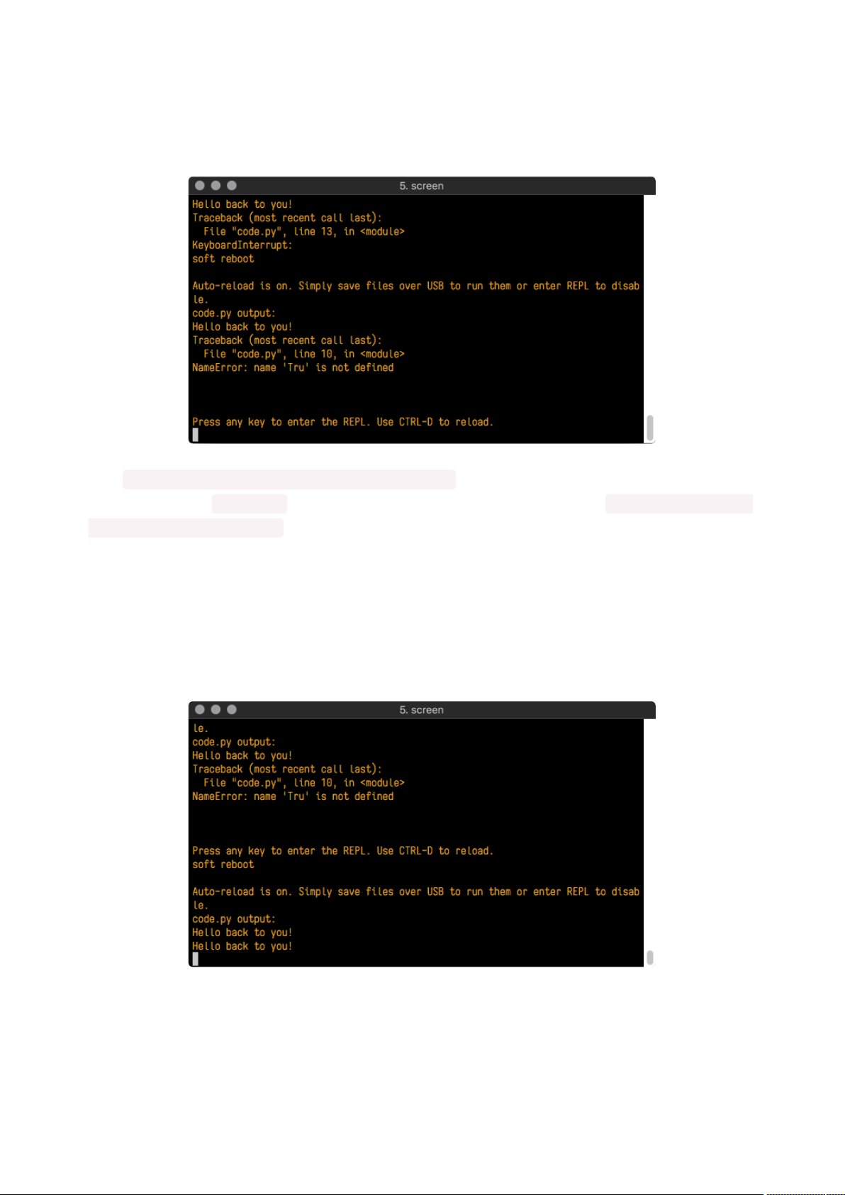
print("Hello back to you!")
led.value = True
time.sleep(1)
led.value = False
time.sleep(1)
Keep your serial console window where you can see it. Save your file. You'll see what
the serial console displays when the board reboots. Then you'll see your new change!
The Traceback (most recent call last): is telling you the last thing your board
was doing before you saved your file. This is normal behavior and will happen every
time the board resets. This is really handy for troubleshooting. Let's introduce an error
so you can see how it is used.
Delete the e at the end of True from the line led.value = True so that it says le
d.value = Tru
import board
import digitalio
import time
led = digitalio.DigitalInOut(board.LED)
led.direction = digitalio.Direction.OUTPUT
while True:
print("Hello back to you!")
led.value = Tru
time.sleep(1)
led.value = False
time.sleep(1)
Save your file. You will notice that your red LED will stop blinking, and you may have a
colored status LED blinking at you. This is because the code is no longer correct and
can no longer run properly. You need to fix it!
©Adafruit Industries Page 40 of 199
Usually when you run into errors, it's not because you introduced them on purpose.
You may have 200 lines of code, and have no idea where your error could be hiding.
This is where the serial console can help. Let's take a look!
The Traceback (most recent call last): is telling you that the last thing it was
able to run was line 10 in your code. The next line is your error: NameError: name
'Tru' is not defined . This error might not mean a lot to you, but combined with
knowing the issue is on line 10, it gives you a great place to start!
Go back to your code, and take a look at line 10. Obviously, you know what the
problem is already. But if you didn't, you'd want to look at line 10 and see if you could
figure it out. If you're still unsure, try googling the error to get some help. In this case,
you know what to look for. You spelled True wrong. Fix the typo and save your file.
Nice job fixing the error! Your serial console is streaming and your red LED Is blinking
again.
The serial console will display any output generated by your code. Some sensors,
such as a humidity sensor or a thermistor, receive data and you can use print
©Adafruit Industries Page 41 of 199

statements to display that information. You can also use print statements for
troubleshooting, which is called "print debugging". Essentially, if your code isn't
working, and you want to know where it's failing, you can put print statements in
various places to see where it stops printing.
The serial console has many uses, and is an amazing tool overall for learning and
programming!
The REPL
The other feature of the serial connection is the Read-Evaluate-Print-Loop, or REPL.
The REPL allows you to enter individual lines of code and have them run immediately.
It's really handy if you're running into trouble with a particular program and can't
figure out why. It's interactive so it's great for testing new ideas.
Entering the REPL
To use the REPL, you first need to be connected to the serial console. Once that
connection has been established, you'll want to press CTRL+C.
If there is code running, in this case code measuring distance, it will stop and you'll
see Press any key to enter the REPL. Use CTRL-D to reload. Follow those
instructions, and press any key on your keyboard.
The Traceback (most recent call last): is telling you the last thing your board
was doing before you pressed Ctrl + C and interrupted it. The KeyboardInterrupt
is you pressing CTRL+C. This information can be handy when troubleshooting, but for
now, don't worry about it. Just note that it is expected behavior.
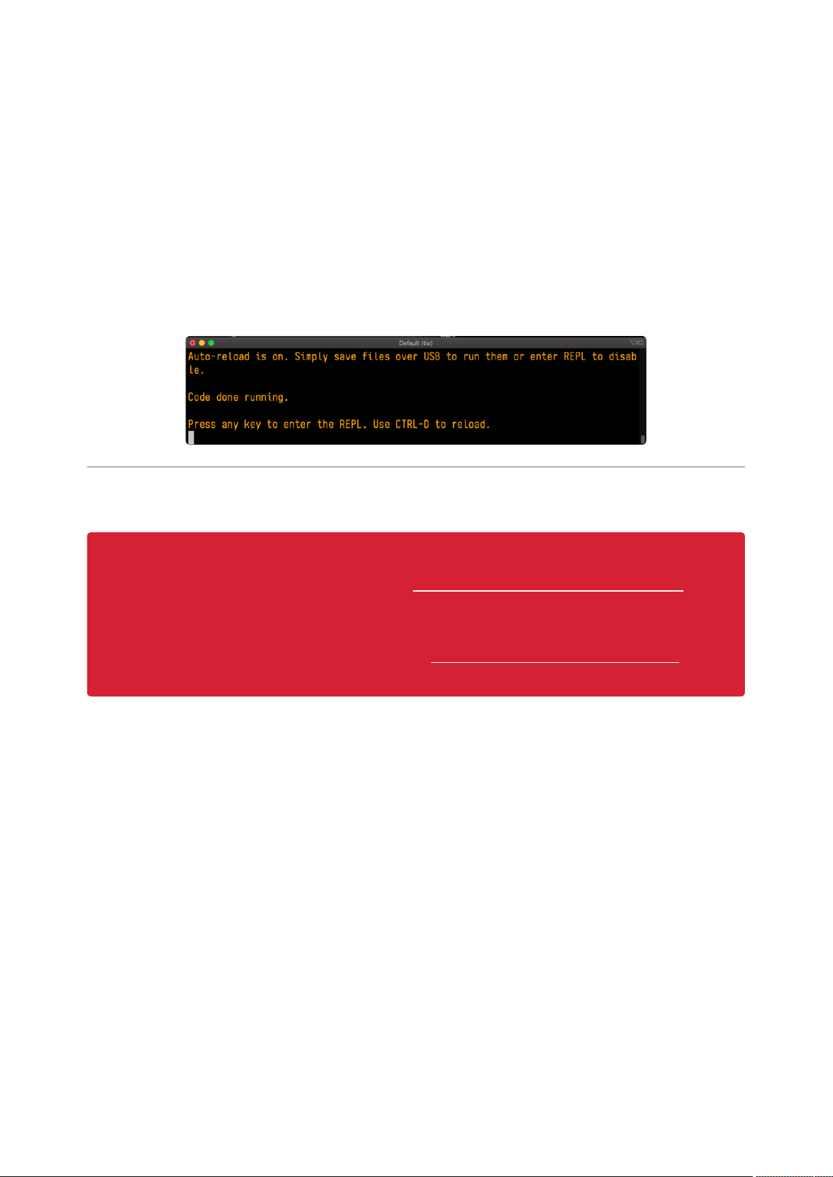
If your code.py file is empty or does not contain a loop, it will show an empty output
and Code done running. . There is no information about what your board was
doing before you interrupted it because there is no code running.
©Adafruit Industries Page 42 of 199

If you have no code.py on your CIRCUITPY drive, you will enter the REPL immediately
after pressing CTRL+C. Again, there is no information about what your board was
doing before you interrupted it because there is no code running.
Regardless, once you press a key you'll see a >>> prompt welcoming you to the
REPL!
If you have trouble getting to the >>> prompt, try pressing Ctrl + C a few more times.
The first thing you get from the REPL is information about your board.
This line tells you the version of CircuitPython you're using and when it was released.
Next, it gives you the type of board you're using and the type of microcontroller the
board uses. Each part of this may be different for your board depending on the
versions you're working with.
This is followed by the CircuitPython prompt.
Interacting with the REPL
From this prompt you can run all sorts of commands and code. The first thing you'll do
is run help() . This will tell you where to start exploring the REPL. To run code in the
REPL, type it in next to the REPL prompt.
Type help() next to the prompt in the REPL.
©Adafruit Industries Page 43 of 199

Then press enter. You should then see a message.
First part of the message is another reference to the version of CircuitPython you're
using. Second, a URL for the CircuitPython related project guides. Then... wait. What's
this? To list built-in modules type `help("modules")`. Remember the
modules you learned about while going through creating code? That's exactly what
this is talking about! This is a perfect place to start. Let's take a look!
Type help("modules") into the REPL next to the prompt, and press enter.
This is a list of all the core modules built into CircuitPython, including board .
Remember, board contains all of the pins on the board that you can use in your
code. From the REPL, you are able to see that list!
Type import board into the REPL and press enter. It'll go to a new prompt. It might
look like nothing happened, but that's not the case! If you recall, the import
statement simply tells the code to expect to do something with that module. In this
case, it's telling the REPL that you plan to do something with that module.
Next, type dir(board) into the REPL and press enter.
©Adafruit Industries Page 44 of 199

This is a list of all of the pins on your board that are available for you to use in your
code. Each board's list will differ slightly depending on the number of pins available.
Do you see LED ? That's the pin you used to blink the red LED!
The REPL can also be used to run code. Be aware that any code you enter into the
REPL isn't saved anywhere. If you're testing something new that you'd like to keep,
make sure you have it saved somewhere on your computer as well!
Every programmer in every programming language starts with a piece of code that
says, "Hello, World." You're going to say hello to something else. Type into the REPL:
print("Hello, CircuitPython!")
Then press enter.
That's all there is to running code in the REPL! Nice job!
You can write single lines of code that run stand-alone. You can also write entire
programs into the REPL to test them. Remember that nothing typed into the REPL is
saved.
There's a lot the REPL can do for you. It's great for testing new ideas if you want to
see if a few new lines of code will work. It's fantastic for troubleshooting code by
entering it one line at a time and finding out where it fails. It lets you see what
modules are available and explore those modules.
Try typing more into the REPL to see what happens!
Everything typed into the REPL is ephemeral. Once you reload the REPL or return
to the serial console, nothing you typed will be retained in any memory space. So
be sure to save any desired code you wrote somewhere else, or you'll lose it
when you leave the current REPL instance!
©Adafruit Industries Page 45 of 199
Returning to the Serial Console
When you're ready to leave the REPL and return to the serial console, simply press CT
RL+D. This will reload your board and reenter the serial console. You will restart the
program you had running before entering the REPL. In the console window, you'll see
any output from the program you had running. And if your program was affecting
anything visual on the board, you'll see that start up again as well.
You can return to the REPL at any time!
CircuitPython Libraries
As CircuitPython development continues and there are new releases, Adafruit
will stop supporting older releases. Visit https://circuitpython.org/downloads to
download the latest version of CircuitPython for your board. You must download
the CircuitPython Library Bundle that matches your version of CircuitPython.
Please update CircuitPython and then visit https://circuitpython.org/libraries to
download the latest Library Bundle.
Each CircuitPython program you run needs to have a lot of information to work. The
reason CircuitPython is so simple to use is that most of that information is stored in
other files and works in the background. These files are called libraries. Some of them
are built into CircuitPython. Others are stored on your CIRCUITPY drive in a folder
called lib. Part of what makes CircuitPython so great is its ability to store code
separately from the firmware itself. Storing code separately from the firmware makes
it easier to update both the code you write and the libraries you depend.
Your board may ship with a lib folder already, it's in the base directory of the drive. If
not, simply create the folder yourself. When you first install CircuitPython, an empty lib
directory will be created for you.
©Adafruit Industries Page 46 of 199

CircuitPython libraries work in the same way as regular Python modules so the Python
docs() are an excellent reference for how it all should work. In Python terms, you can
place our library files in the lib directory because it's part of the Python path by
default.
One downside of this approach of separate libraries is that they are not built in. To
use them, one needs to copy them to the CIRCUITPY drive before they can be used.
Fortunately, there is a library bundle.
The bundle and the library releases on GitHub also feature optimized versions of the
libraries with the .mpy file extension. These files take less space on the drive and
have a smaller memory footprint as they are loaded.
Due to the regular updates and space constraints, Adafruit does not ship boards with
the entire bundle. Therefore, you will need to load the libraries you need when you
begin working with your board. You can find example code in the guides for your
board that depends on external libraries.
Either way, as you start to explore CircuitPython, you'll want to know how to get
libraries on board.
The Adafruit Learn Guide Project Bundle
The quickest and easiest way to get going with a project from the Adafruit Learn
System is by utilising the Project Bundle. Most guides now have a Download Project
Bundle button available at the top of the full code example embed. This button
downloads all the necessary files, including images, etc., to get the guide project up
and running. Simply click, open the resulting zip, copy over the right files, and you're
good to go!
The first step is to find the Download Project Bundle button in the guide you're
working on.
©Adafruit Industries Page 47 of 199

The Download Project Bundle button is only available on full demo code
embedded from GitHub in a Learn guide. Code snippets will NOT have the
button available.
When you copy the contents of the Project Bundle to your CIRCUITPY drive, it
will replace all the existing content! If you don't want to lose anything, ensure you
copy your current code to your computer before you copy over the new Project
Bundle content!
The Download Project Bundle button downloads a zip file. This zip contains a series
of directories, nested within which is the code.py, any applicable assets like images or
audio, and the lib/ folder containing all the necessary libraries. The following zip was
downloaded from the Piano in the Key of Lime guide.
The Piano in the Key of Lime guide was chosen as an example. That guide is
specific to Circuit Playground Express, and cannot be used on all boards. Do not
©Adafruit Industries Page 48 of 199

expect to download that exact bundle and have it work on your non-CPX
microcontroller.
When you open the zip, you'll find some nested directories. Navigate through them
until you find what you need. You'll eventually find a directory for your CircuitPython
version (in this case, 7.x). In the version directory, you'll find the file and directory you
need: code.py and lib/. Once you find the content you need, you can copy it all over
to your CIRCUITPY drive, replacing any files already on the drive with the files from
the freshly downloaded zip.
In some cases, there will be other files such as audio or images in the same
directory as code.py and lib/. Make sure you include all the files when you copy
things over!
Once you copy over all the relevant files, the project should begin running! If you find
that the project is not running as expected, make sure you've copied ALL of the
project files onto your microcontroller board.
That's all there is to using the Project Bundle!
The Adafruit CircuitPython Library Bundle
Adafruit provides CircuitPython libraries for much of the hardware they provide,
including sensors, breakouts and more. To eliminate the need for searching for each
library individually, the libraries are available together in the Adafruit CircuitPython
Library Bundle. The bundle contains all the files needed to use each library.
Downloading the Adafruit CircuitPython Library Bundle
You can download the latest Adafruit CircuitPython Library Bundle release by clicking
the button below. The libraries are being constantly updated and improved, so you'll
always want to download the latest bundle.
Match up the bundle version with the version of CircuitPython you are running. For
example, you would download the 6.x library bundle if you're running any version of
CircuitPython 6, or the 7.x library bundle if you're running any version of CircuitPython
7, etc. If you mix libraries with major CircuitPython versions, you will get incompatible
mpy errors due to changes in library interfaces possible during major version
changes.
©Adafruit Industries Page 49 of 199

Click to visit circuitpython.org for the
latest Adafruit CircuitPython Library
Bundle
Download the bundle version that matches your CircuitPython firmware version. If you
don't know the version, check the version info in boot_out.txt file on the CIRCUITPY
drive, or the initial prompt in the CircuitPython REPL. For example, if you're running
v7.0.0, download the 7.x library bundle.
There's also a py bundle which contains the uncompressed python files, you probably
don't want that unless you are doing advanced work on libraries.
The CircuitPython Community Library Bundle
The CircuitPython Community Library Bundle is made up of libraries written and
provided by members of the CircuitPython community. These libraries are often
written when community members encountered hardware not supported in the
Adafruit Bundle, or to support a personal project. The authors all chose to submit
these libraries to the Community Bundle make them available to the community.
These libraries are maintained by their authors and are not supported by Adafruit. As
you would with any library, if you run into problems, feel free to file an issue on the
GitHub repo for the library. Bear in mind, though, that most of these libraries are
supported by a single person and you should be patient about receiving a response.
Remember, these folks are not paid by Adafruit, and are volunteering their personal
time when possible to provide support.
Downloading the CircuitPython Community Library Bundle
You can download the latest CircuitPython Community Library Bundle release by
clicking the button below. The libraries are being constantly updated and improved,
so you'll always want to download the latest bundle.
Click for the latest CircuitPython
Community Library Bundle release
The link takes you to the latest release of the CircuitPython Community Library
Bundle on GitHub. There are multiple versions of the bundle available. Download the
bundle version that matches your CircuitPython firmware version. If you don't know
©Adafruit Industries Page 50 of 199

the version, check the version info in boot_out.txt file on the CIRCUITPY drive, or the
initial prompt in the CircuitPython REPL. For example, if you're running v7.0.0,
download the 7.x library bundle.
Understanding the Bundle
After downloading the zip, extract its contents. This is usually done by double clicking
on the zip. On Mac OSX, it places the file in the same directory as the zip.
Open the bundle folder. Inside you'll find two information files, and two folders. One
folder is the lib bundle, and the other folder is the examples bundle.
Now open the lib folder. When you open the folder, you'll see a large number of .mpy
files, and folders.
Example Files
All example files from each library are now included in the bundles in an examples
directory (as seen above), as well as an examples-only bundle. These are included for
two main reasons:
Allow for quick testing of devices.
•
©Adafruit Industries Page 51 of 199

Provide an example base of code, that is easily built upon for individualized
•
purposes.
Copying Libraries to Your Board
First open the lib folder on your CIRCUITPY drive. Then, open the lib folder you
extracted from the downloaded zip. Inside you'll find a number of folders and .mpy
files. Find the library you'd like to use, and copy it to the lib folder on CIRCUITPY.
If the library is a directory with multiple .mpy files in it, be sure to copy the entire
folder to CIRCUITPY/lib.
This also applies to example files. Open the examples folder you extracted from the
downloaded zip, and copy the applicable file to your CIRCUITPY drive. Then, rename
it to code.py to run it.
If a library has multiple .mpy files contained in a folder, be sure to copy the entire
folder to CIRCUITPY/lib.
Understanding Which Libraries to Install
You now know how to load libraries on to your CircuitPython-compatible
microcontroller board. You may now be wondering, how do you know which libraries
you need to install? Unfortunately, it's not always straightforward. Fortunately, there is
an obvious place to start, and a relatively simple way to figure out the rest. First up:
the best place to start.
When you look at most CircuitPython examples, you'll see they begin with one or
more import statements. These typically look like the following:
import library_or_module
•
©Adafruit Industries Page 52 of 199

However, import statements can also sometimes look like the following:
from library_or_module import name
•
from library_or_module.subpackage import name
•
from library_or_module import name as local_name
•
They can also have more complicated formats, such as including a try / except
block, etc.
The important thing to know is that an import statement will always include the
name of the module or library that you're importing.
Therefore, the best place to start is by reading through the import statements.
Here is an example import list for you to work with in this section. There is no setup or
other code shown here, as the purpose of this section involves only the import list.
import time
import board
import neopixel
import adafruit_lis3dh
import usb_hid
from adafruit_hid.consumer_control import ConsumerControl
from adafruit_hid.consumer_control_code import ConsumerControlCode
Keep in mind, not all imported items are libraries. Some of them are almost always
built-in CircuitPython modules. How do you know the difference? Time to visit the
REPL.
In the Interacting with the REPL section() on The REPL page() in this guide, the
help("modules") command is discussed. This command provides a list of all of the
built-in modules available in CircuitPython for your board. So, if you connect to the
serial console on your board, and enter the REPL, you can run help("modules") to
see what modules are available for your board. Then, as you read through the impor
t statements, you can, for the purposes of figuring out which libraries to load, ignore
the statement that import modules.
The following is the list of modules built into CircuitPython for the Feather RP2040.
Your list may look similar or be anything down to a significant subset of this list for
smaller boards.
©Adafruit Industries Page 53 of 199

Now that you know what you're looking for, it's time to read through the import
statements. The first two, time and board , are on the modules list above, so they're
built-in.
The next one, neopixel , is not on the module list. That means it's your first library!
So, you would head over to the bundle zip you downloaded, and search for neopixel.
There is a neopixel.mpy file in the bundle zip. Copy it over to the lib folder on your CI
RCUITPY drive. The following one, adafruit_lis3dh , is also not on the module list.
Follow the same process for adafruit_lis3dh, where you'll find adafruit_lis3dh.mpy,
and copy that over.
The fifth one is usb_hid , and it is in the modules list, so it is built in. Often all of the
built-in modules come first in the import list, but sometimes they don't! Don't assume
that everything after the first library is also a library, and verify each import with the
modules list to be sure. Otherwise, you'll search the bundle and come up empty!
The final two imports are not as clear. Remember, when import statements are
formatted like this, the first thing after the from is the library name. In this case, the
library name is adafruit_hid . A search of the bundle will find an adafruit_hid folder.
When a library is a folder, you must copy the entire folder and its contentsas it is in
the bundle to the lib folder on your CIRCUITPY drive. In this case, you would copy the
entire adafruit_hid folder to your CIRCUITPY/lib folder.
Notice that there are two imports that begin with adafruit_hid . Sometimes you will
need to import more than one thing from the same library. Regardless of how many
times you import the same library, you only need to load the library by copying over
the adafruit_hid folder once.
That is how you can use your example code to figure out what libraries to load on
your CircuitPython-compatible board!
©Adafruit Industries Page 54 of 199

There are cases, however, where libraries require other libraries internally. The
internally required library is called a dependency. In the event of library
dependencies, the easiest way to figure out what other libraries are required is to
connect to the serial console and follow along with the ImportError printed there.
The following is a very simple example of an ImportError , but the concept is the
same for any missing library.
Example: ImportError Due to Missing Library
If you choose to load libraries as you need them, or you're starting fresh with an
existing example, you may end up with code that tries to use a library you haven't yet
loaded. This section will demonstrate what happens when you try to utilise a library
that you don't have loaded on your board, and cover the steps required to resolve the
issue.
This demonstration will only return an error if you do not have the required library
loaded into the lib folder on your CIRCUITPY drive.
Let's use a modified version of the Blink example.
import board
import time
import simpleio
led = simpleio.DigitalOut(board.LED)
while True:
led.value = True
time.sleep(0.5)
led.value = False
time.sleep(0.5)
Save this file. Nothing happens to your board. Let's check the serial console to see
what's going on.
©Adafruit Industries Page 55 of 199

You have an ImportError . It says there is no module named 'simpleio' . That's
the one you just included in your code!
Click the link above to download the correct bundle. Extract the lib folder from the
downloaded bundle file. Scroll down to find simpleio.mpy. This is the library file you're
looking for! Follow the steps above to load an individual library file.
The LED starts blinking again! Let's check the serial console.
No errors! Excellent. You've successfully resolved an ImportError !
If you run into this error in the future, follow along with the steps above and choose
the library that matches the one you're missing.
Library Install on Non-Express Boards
If you have an M0 non-Express board such as Trinket M0, Gemma M0, QT Py M0, or
one of the M0 Trinkeys, you'll want to follow the same steps in the example above to
install libraries as you need them. Remember, you don't need to wait for an ImportEr
ror if you know what library you added to your code. Open the library bundle you
downloaded, find the library you need, and drag it to the lib folder on your CIRCUITPY
drive.
You can still end up running out of space on your M0 non-Express board even if you
only load libraries as you need them. There are a number of steps you can use to try
to resolve this issue. You'll find suggestions on the Troubleshooting page().
Updating CircuitPython Libraries and Examples
Libraries and examples are updated from time to time, and it's important to update the
files you have on your CIRCUITPY drive.
To update a single library or example, follow the same steps above. When you drag
the library file to your lib folder, it will ask if you want to replace it. Say yes. That's it!
©Adafruit Industries Page 56 of 199

A new library bundle is released every time there's an update to a library. Updates
include things like bug fixes and new features. It's important to check in every so
often to see if the libraries you're using have been updated.
CircUp CLI Tool
There is a command line interface (CLI) utility called CircUp() that can be used to
easily install and update libraries on your device. Follow the directions on the install
page within the CircUp learn guide(). Once you've got it installed you run the
command circup update in a terminal to interactively update all libraries on the
connected CircuitPython device. See the usage page in the CircUp guide() for a full
list of functionality
CircuitPython Documentation
You've learned about the CircuitPython built-in modules and external libraries. You
know that you can find the modules in CircuitPython, and the libraries in the Library
Bundles. There are guides available that explain the basics of many of the modules
and libraries. However, there's sometimes more capabilities than are necessarily
showcased in the guides, and often more to learn about a module or library. So,
where can you find more detailed information? That's when you want to look at the
API documentation.
The entire CircuitPython project comes with extensive documentation available on
Read the Docs. This includes both the CircuitPython core() and the Adafruit
CircuitPython libraries().
CircuitPython Core Documentation
The CircuitPython core documentation() covers many of the details you might want to
know about the CircuitPython core and related topics. It includes API and usage info,
a design guide and information about porting CircuitPython to new boards,
MicroPython info with relation to CircuitPython, and general information about the
project.
©Adafruit Industries Page 57 of 199

The main page covers the basics including where to download CircuitPython, how to
contribute, differences from MicroPython, information about the project structure, and
a full table of contents for the rest of the documentation.
The list along the left side leads to more information about specific topics.
The first section is API and Usage. This is where you can find information about how
to use individual built-in core modules, such as time and digitalio , details about
the supported ports, suggestions for troubleshooting, and basic info and links to the li
brary bundles. The Core Modules section also includes the Support Matrix, which is a
table of which core modules are available on which boards.
The second section is Design and Porting Reference. It includes a design guide, archit
ecture information, details onporting, and adding module support to other ports.
The third section is MicroPython Specific. It includes information on MicroPython and
related libraries, and a glossary of terms.
The fourth and final section is About the Project. It includes further information
including details on building, testing, and debugging CircuitPython, along with various
other useful links including the Adafruit Community Code of Conduct.
Whether you're a seasoned pro or new to electronics and programming, you'll find a
wealth of information to help you along your CircuitPython journey in the
documentation!
©Adafruit Industries Page 58 of 199

CircuitPython Library Documentation
The Adafruit CircuitPython libraries are documented in a very similar fashion. Each
library has its own page on Read the Docs. There is a comprehensive list available her
e(). Otherwise, to view the documentation for a specific library, you can visit the
GitHub repository for the library, and find the link in the README.
For the purposes of this page, the LED Animation library() documentation will be
featured. There are two links to the documentation in each library GitHub repo. The
first one is the docs badge near the top of the README.
The second place is the Documentation section of the README. Scroll down to find it,
and click on Read the Docs to get to the documentation.
Now that you know how to find it, it's time to take a look at what to expect.
Not all library documentation will look exactly the same, but this will give you
some idea of what to expect from library docs.
The Introduction page is generated from the README, so it includes all the same info,
such as PyPI installation instructions, a quick demo, and some build details. It also
includes a full table of contents for the rest of the documentation (which is not part of
the GitHub README). The page should look something like the following.
The left side contains links to the rest of the documentation, divided into three
separate sections: Examples, API Reference, and Other Links.
©Adafruit Industries Page 59 of 199

Examples
The Examples section() is a list of library examples. This list contains anywhere from a
small selection to the full list of the examples available for the library.
This section will always contain at least one example - the simple test example.
The simple test example is usually a basic example designed to show your setup is
working. It may require other libraries to run. Keep in mind, it's simple - it won't
showcase a comprehensive use of all the library features.
The LED Animation simple test demonstrates the Blink animation.
In some cases, you'll find a longer list, that may include examples that explore other
features in the library. The LED Animation documentation includes a series of
examples, all of which are available in the library. These examples include
demonstrations of both basic and more complex features. Simply click on the example
that interests you to view the associated code.
©Adafruit Industries Page 60 of 199

When there are multiple links in the Examples section, all of the example content
is, in actuality, on the same page. Each link after the first is an anchor link to the
specified section of the page. Therefore, you can also view all the available
examples by scrolling down the page.
You can view the rest of the examples by clicking through the list or scrolling down
the page. These examples are fully working code. Which is to say, while they may rely
on other libraries as well as the library for which you are viewing the documentation,
they should not require modification to otherwise work.
API Reference
The API Reference section() includes a list of the library functions and classes. The
API (Application Programming Interface) of a library is the set of functions and classes
the library provides. Essentially, the API defines how your program interfaces with the
functions and classes that you call in your code to use the library.
There is always at least one list item included. Libraries for which the code is included
in a single Python (.py) file, will only have one item. Libraries for which the code is
multiple Python files in a directory (called subpackages) will have multiple items in this
list. The LED Animation library has a series of subpackages, and therefore, multiple
items in this list.
Click on the first item in the list to begin viewing the API Reference section.
As with the Examples section, all of the API Reference content is on a single
page, and the links under API Reference are anchor links to the specified section
of the page.
When you click on an item in the API Reference section, you'll find details about the
classes and functions in the library. In the case of only one item in this section, all the
©Adafruit Industries Page 61 of 199

available functionality of the library will be contained within that first and only
subsection. However, in the case of a library that has subpackages, each item will
contain the features of the particular subpackage indicated by the link. The
documentation will cover all of the available functions of the library, including more
complex ones that may not interest you.
The first list item is the animation subpackage. If you scroll down, you'll begin to see
the available features of animation. They are listed alphabetically. Each of these
things can be called in your code. It includes the name and a description of the
specific function you would call, and if any parameters are necessary, lists those with
a description as well.
You can view the other subpackages by clicking the link on the left or scrolling down
the page. You may be interested in something a little more practical. Here is an
example. To use the LED Animation library Comet animation, you would run the
following example.
# SPDX-FileCopyrightText: 2021 Kattni Rembor for Adafruit Industries
# SPDX-License-Identifier: MIT
"""
This example animates a jade comet that bounces from end to end of the strip.
For QT Py Haxpress and a NeoPixel strip. Update pixel_pin and pixel_num to match
your wiring if
using a different board or form of NeoPixels.
This example will run on SAMD21 (M0) Express boards (such as Circuit Playground
Express or QT Py
Haxpress), but not on SAMD21 non-Express boards (such as QT Py or Trinket).
"""
import board
import neopixel
from adafruit_led_animation.animation.comet import Comet
from adafruit_led_animation.color import JADE
# Update to match the pin connected to your NeoPixels
pixel_pin = board.A3
# Update to match the number of NeoPixels you have connected
pixel_num = 30
©Adafruit Industries Page 62 of 199

pixels = neopixel.NeoPixel(pixel_pin, pixel_num, brightness=0.5, auto_write=False)
comet = Comet(pixels, speed=0.02, color=JADE, tail_length=10, bounce=True)
while True:
comet.animate()
Note the line where you create the comet object. There are a number of items inside
the parentheses. In this case, you're provided with a fully working example. But what
if you want to change how the comet works? The code alone does not explain what
the options mean.
So, in the API Reference documentation list, click the
adafruit_led_animation.animation.comet link and scroll down a bit until you
see the following.
Look familiar? It is! This is the documentation for setting up the comet object. It
explains what each argument provided in the comet setup in the code meant, as well
as the other available features. For example, the code includes speed=0.02 . The
documentation clarifies that this is the "Animation speed in seconds". The code
doesn't include ring . The documentation indicates this is an available setting that
enables "Ring mode".
This type of information is available for any function you would set up in your code. If
you need clarification on something, wonder whether there's more options available,
or are simply interested in the details involved in the code you're writing, check out
the documentation for the CircuitPython libraries!
©Adafruit Industries Page 63 of 199

Other Links
This section is the same for every library. It includes a list of links to external sites,
which you can visit for more information about the CircuitPython Project and Adafruit.
That covers the CircuitPython library documentation! When you are ready to go
beyond the basic library features covered in a guide, or you're interested in
understanding those features better, the library documentation on Read the Docs has
you covered!
Recommended Editors
The CircuitPython code on your board detects when the files are changed or written
and will automatically re-start your code. This makes coding very fast because you
save, and it re-runs.
However, you must wait until the file is done being saved before unplugging or
resetting your board! On Windows using some editors this can sometimes take up to
90 seconds, on Linux it can take 30 seconds to complete because the text editor
does not save the file completely. Mac OS does not seem to have this delay, which is
nice!
This is really important to be aware of. If you unplug or reset the board before your
computer finishes writing the file to your board, you can corrupt the drive. If this
happens, you may lose the code you've written, so it's important to backup your code
to your computer regularly.
To avoid the likelihood of filesystem corruption, use an editor that writes out the file
completely when you save it. Check out the list of recommended editors below.
Recommended editors
mu() is an editor that safely writes all changes (it's also our recommended
•
editor!)
emacs() is also an editor that will fulIy write files on save()
•
Sublime Text()safelywrites all changes
•
Visual Studio Code() appears to safely write all changes
•
gedit on Linux appears to safely write all changes
•
IDLE(), in Python 3.8.1 or later, was fixed() to write all changes immediately
•
Thonny() fully writes files on save
•
©Adafruit Industries Page 64 of 199

Recommended only with particular settings or add-ons
vim()/visafely writes all changes. But set upvimto not write swapfiles() (.swp
•
files: temporary records of your edits) to CIRCUITPY. Run vim with vim -n ,set
the no swapfile option, or set the directory option to write swapfiles
elsewhere. Otherwise the swapfile writestrigger restarts of your program.
ThePyCharm IDE()is safe if "Safe Write" is turned on in Settings->System
•
Settings->Synchronization (true by default).
If you are usingAtom(), install thefsync-on-save package() or the language-
•
circuitpython package() so that it will always write out all changes to files on CIR
CUITPY.
SlickEdit()works only if youadd a macro to flush the disk().
•
The editors listed below are specifically NOT recommended!
Editors that are NOT recommended
notepad (the default Windows editor) and Notepad++ can be slow to write, so
•
the editors above are recommended! If you are using notepad, be sure to eject
the drive.
IDLE in Python 3.8.0 or earlier does not force out changes immediately.
•
nano (on Linux) does not force out changes.
•
geany (on Linux) does not force out changes.
•
Anything else - Other editors have not been tested so please use a
•
recommended one!
Advanced Serial Console on Windows
Windows 7 and 8.1
If you're using Windows 7 (or 8 or 8.1), you'll need to install drivers. See the Windows 7
and 8.1 Drivers page() for details. You will not need to install drivers on Mac, Linux or
Windows 10.
You are strongly encouraged to upgrade to Windows 10 if you are still using Windows
7 or Windows 8 or 8.1. Windows 7 has reached end-of-life and no longer receives
security updates. A free upgrade to Windows 10 is still available().
©Adafruit Industries Page 65 of 199

What's the COM?
First, you'll want to find out which serial port your board is using. When you plug your
board in to USB on your computer, it connects to a serial port. The port is like a door
through which your board can communicate with your computer using USB.
You'll use Windows Device Manager to determine which port the board is using. The
easiest way to determine which port the board is using is to first check without the
board plugged in. Open Device Manager. Click on Ports (COM & LPT). You should find
something already in that list with (COM#) after it where # is a number.
Now plug in your board. The Device Manager list will refresh and a new item will
appear under Ports (COM & LPT). You'll find a different (COM#) after this item in the
list.
©Adafruit Industries Page 66 of 199

Sometimes the item will refer to the name of the board. Other times it may be called
something like USB Serial Device, as seen in the image above. Either way, there is a
new (COM#) following the name. This is the port your board is using.
Install Putty
If you're using Windows, you'll need to download a terminal program. You're going to
use PuTTY.
The first thing to do is download the latest version of PuTTY(). You'll want to
download the Windows installer file. It is most likely that you'll need the 64-bit version.
Download the file and install the program on your machine. If you run into issues, you
can try downloading the 32-bit version instead. However, the 64-bit version will work
on most PCs.
Now you need to open PuTTY.
Under Connection type: choose the button next to Serial.
•
In the box under Serial line, enter the serial port you found that your board is
•
using.
In the box under Speed, enter 115200. This called the baud rate, which is the
•
speed in bits per second that data is sent over the serial connection. For boards
with built in USB it doesn't matter so much but for ESP8266 and other board
with a separate chip, the speed required by the board is 115200 bits per second.
So you might as well just use 115200!
©Adafruit Industries Page 67 of 199

If you want to save those settings for later, use the options under Load, save or delete
a stored session. Enter a name in the box under Saved Sessions, and click the Save
button on the right.
Once your settings are entered, you're ready to connect to the serial console. Click
"Open" at the bottom of the window. A new window will open.
If no code is running, the window will either be blank or will look like the window
above. Now you're ready to see the results of your code.
©Adafruit Industries Page 68 of 199

Great job! You've connected to the serial console!
Advanced Serial Console on Mac
Connecting to the serial console on Mac does not require installing any drivers or
extra software. You'll use a terminal program to find your board, and screen to
connect to it. Terminal and screen both come installed by default.
What's the Port?
First you'll want to find out which serial port your board is using. When you plug your
board in to USB on your computer, it connects to a serial port. The port is like a door
through which your board can communicate with your computer using USB.
The easiest way to determine which port the board is using is to first check without
the board plugged in. Open Terminal and type the following:
ls /dev/tty.*
Each serial connection shows up in the /dev/ directory. It has a name that starts with
tty. . The command ls shows you a list of items in a directory. You can use * as a
wildcard, to search for files that start with the same letters but end in something
different. In this case, you're asking to see all of the listings in /dev/ that start with t
ty. and end in anything. This will show us the current serial connections.
Now, plug your board. In Terminal, type:
ls /dev/tty.*
©Adafruit Industries Page 69 of 199

This will show you the current serial connections, which will now include your board.
A new listing has appeared called /dev/tty.usbmodem141441 . The tty.usbmodem1
41441 part of this listing is the name the example board is using. Yours will be called
something similar.
Using Linux, a new listing has appeared called /dev/ttyACM0 . The ttyACM0 part of
this listing is the name the example board is using. Yours will be called something
similar.
Connect with screen
Now that you know the name your board is using, you're ready connect to the serial
console. You're going to use a command called screen . The screen command is
included with MacOS. To connect to the serial console, use Terminal. Type the
following command, replacing board_name with the name you found your board is
using:
screen /dev/tty.board_name 115200
The first part of this establishes using the screen command. The second part tells
screen the name of the board you're trying to use. The third part tells screen what
baud rate to use for the serial connection. The baud rate is the speed in bits per
second that data is sent over the serial connection. In this case, the speed required
by the board is 115200 bits per second.
©Adafruit Industries Page 70 of 199

Press enter to run the command. It will open in the same window. If no code is
running, the window will be blank. Otherwise, you'll see the output of your code.
Great job! You've connected to the serial console!
Advanced Serial Console on Linux
Connecting to the serial console on Linux does not require installing any drivers, but
you may need to install screen using your package manager. You'll use a terminal
program to find your board, and screen to connect to it. There are a variety of
terminal programs such as gnome-terminal (called Terminal) or Konsole on KDE.
The tio program works as well to connect to your board, and has the benefit of
automatically reconnecting. You would need to install it using your package manager.
What's the Port?
First you'll want to find out which serial port your board is using. When you plug your
board in to USB on your computer, it connects to a serial port. The port is like a door
through which your board can communicate with your computer using USB.
The easiest way to determine which port the board is using is to first check without
the board plugged in. Open your terminal program and type the following:
ls /dev/ttyACM*
Each serial connection shows up in the /dev/ directory. It has a name that starts with tt
yACM. The command ls shows you a list of items in a directory. You can use * as a
wildcard, to search for files that start with the same letters but end in something
©Adafruit Industries Page 71 of 199

different. In this case, You're asking to see all of the listings in /dev/ that start with ttyA
CM and end in anything. This will show us the current serial connections.
In the example below, the error is indicating that are no current serial connections
starting with ttyACM.
Now plug in your board. In your terminal program, type:
ls /dev/ttyACM*
This will show you the current serial connections, which will now include your board.
A new listing has appeared called /dev/ttyACM0. The ttyACM0 part of this listing is
the name the example board is using. Yours will be called something similar.
Connect with screen
Now that you know the name your board is using, you're ready connect to the serial
console. You'll use a command called screen . You may need to install it using the
package manager.
©Adafruit Industries Page 72 of 199

To connect to the serial console, use your terminal program. Type the following
command, replacing board_name with the name you found your board is using:
screen /dev/tty.board_name 115200
The first part of this establishes using the screen command. The second part tells
screen the name of the board you're trying to use. The third part tells screen what
baud rate to use for the serial connection. The baud rate is the speed in bits per
second that data is sent over the serial connection. In this case, the speed required
by the board is 115200 bits per second.
Press enter to run the command. It will open in the same window. If no code is
running, the window will be blank. Otherwise, you'll see the output of your code.
Great job! You've connected to the serial console!
Permissions on Linux
If you try to run screen and it doesn't work, then you may be running into an issue
with permissions. Linux keeps track of users and groups and what they are allowed to
do and not do, like access the hardware associated with the serial connection for
running screen . So if you see something like this:
then you may need to grant yourself access. There are generally two ways you can do
this. The first is to just run screen using the sudo command, which temporarily
gives you elevated privileges.
©Adafruit Industries Page 73 of 199
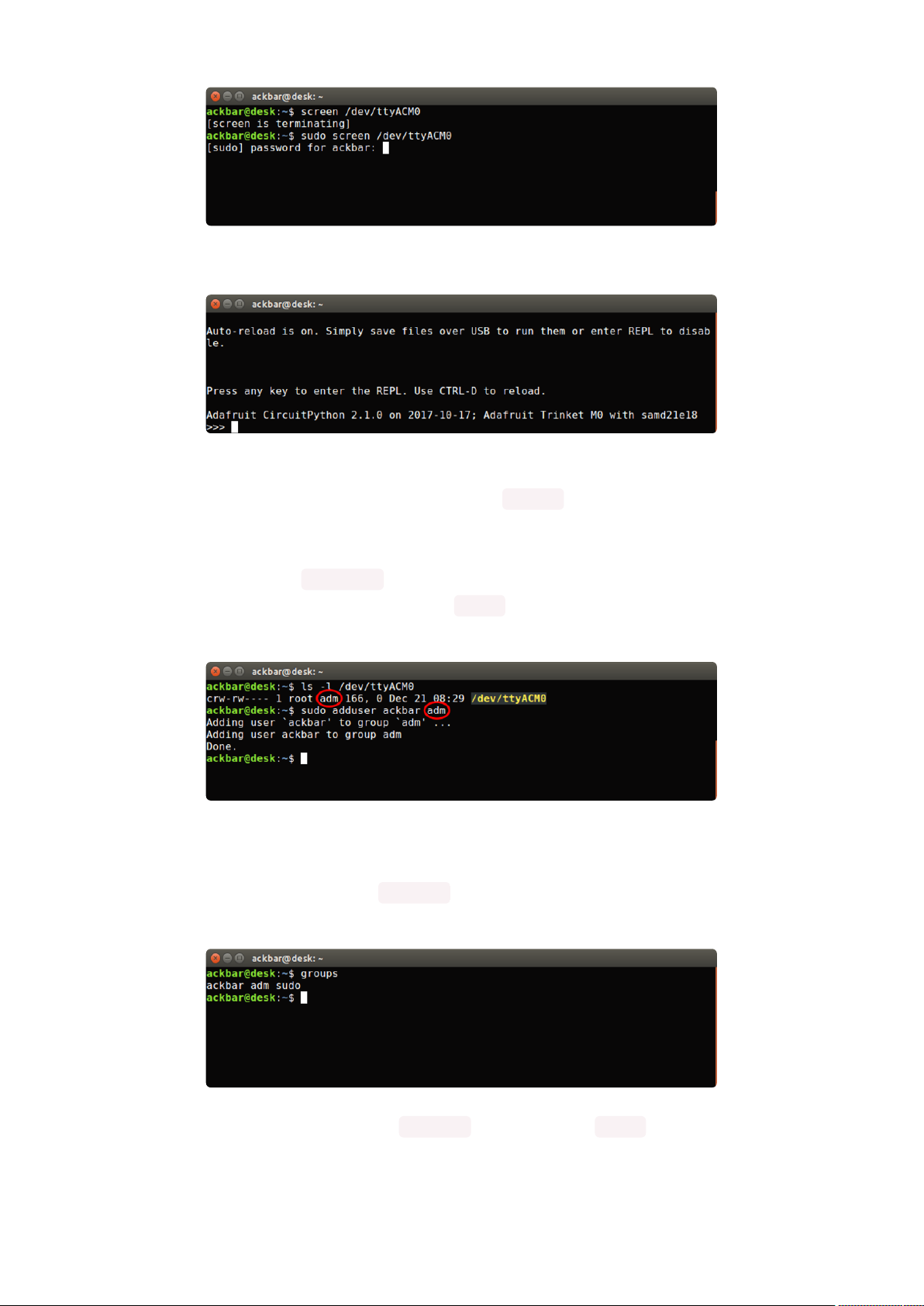
Once you enter your password, you should be in:
The second way is to add yourself to the group associated with the hardware. To
figure out what that group is, use the command ls -l as shown below. The group
name is circled in red.
Then use the command adduser to add yourself to that group. You need elevated
privileges to do this, so you'll need to use sudo . In the example below, the group is a
dm and the user is ackbar.
After you add yourself to the group, you'll need to logout and log back in, or in some
cases, reboot your machine. After you log in again, verify that you have been added
to the group using the command groups . If you are still not in the group, reboot and
check again.
And now you should be able to run screen without using sudo .
©Adafruit Industries Page 74 of 199

And you're in:
The examples above use screen , but you can also use other programs, such as put
ty or picocom , if you prefer.
Frequently Asked Questions
These are some of the common questions regarding CircuitPython and CircuitPython
microcontrollers.
What are some common acronyms to know?
CP or CPy = CircuitPython()
CPC = Circuit Playground Classic()(does not run CircuitPython)
CPX = Circuit Playground Express()
CPB = Circuit Playground Bluefruit()
Using Older Versions
As CircuitPython development continues and there are new releases, Adafruit
will stop supporting older releases. Visit https://circuitpython.org/downloads to
download the latest version of CircuitPython for your board. You must download
the CircuitPython Library Bundle that matches your version of CircuitPython.
Please update CircuitPython and then visit https://circuitpython.org/libraries to
download the latest Library Bundle.
©Adafruit Industries Page 75 of 199

I have to continue using CircuitPython 7.x or earlier. Where can I find compatible libraries?
We are no longer building or supporting the CircuitPython 7.x or earlier library
bundles. We highly encourage you to update CircuitPython to the latest version()
and use the current version of the libraries(). However, if for some reason you
cannot update, here are the last available library bundles for older versions:
2.x bundle()
•
3.x bundle()
•
4.x bundle()
•
5.x bundle()
•
6.x bundle()
•
7.x bundle()
•
Python Arithmetic
Does CircuitPython support floating-point numbers?
All CircuitPython boards support floating point arithmetic, even if the
microcontroller chip does not support floating point in hardware. Floating point
numbers are stored in 30 bits, with an 8-bit exponent and a 22-bit mantissa. Note
that this is two bits less than standard 32-bit single-precision floats. You will get
about 5-1/2 digits of decimal precision.
(Thebroadcomport may provide 64-bit floats in some cases.)
Does CircuitPython support long integers, like regular Python?
Python long integers (integers of arbitrary size) are available on most builds, except
those on boards with the smallest available firmware size. On these boards,
integers are stored in 31 bits.
Boards without long integer support are mostly SAMD21 ("M0") boards without an
external flash chip, such as the Adafruit Gemma M0, Trinket M0, QT Py M0, and the
Trinkey series. There are also a number of third-party boards in this category.
There are also a few small STM third-party boards without long integer support.
time.localtime() , time.mktime() , time.time() , and
time.monotonic_ns() are available only on builds with long integers.
©Adafruit Industries Page 76 of 199

Wireless Connectivity
How do I connect to the Internet with CircuitPython?
If you'd like to include WiFi in your project, your best bet is to use a board that is
running natively on ESP32 chipsets - those have WiFi built in!
If your development board has an SPI port and at least 4 additional pins, you can
check out this guide() on using AirLift with CircuitPython - extra wiring is required
and some boards like the MacroPad or NeoTrellis do not have enough available
pins to add the hardware support.
For further project examples, and guides about using AirLift with specific hardware,
check out the Adafruit Learn System().
How do I do BLE (Bluetooth Low Energy) with CircuitPython?
The nRF52840 and nRF52833 boards have the most complete BLE
implementation. Your program can act as both a BLE central and peripheral. As a
central, you can scan for advertisements, and connect to an advertising board. As a
peripheral, you can advertise, and you can create services available to a central.
Pairing and bonding are supported.
ESP32-C3 and ESP32-S3 boards currently provide an incomplete()BLE
implementation. Your program can act as a central, and connect to a peripheral.
You can advertise, but you cannot create services. You cannot advertise
anonymously. Pairing and bonding are not supported.
The ESP32 could provide a similar implementation, but it is not yet available. Note
that the ESP32-S2 does not have Bluetooth capability.
On most other boards with adequate firmware space, BLE is available for use with
AirLift() or other NINA-FW-based co-processors. Some boards have this
coprocessor on board, such as the PyPortal(). Currently, this implementation only
supports acting as a BLE peripheral. Scanning and connecting as a central are not
yet implemented. Bonding and pairing are not supported.
©Adafruit Industries Page 77 of 199

Are there other ways to communicate by radio with CircuitPython?
Check out Adafruit's RFM boards ()for simple radio communication supported by
CircuitPython, which can be used over distances of 100m to over a km, depending
on the version. The RFM SAMD21 M0 boards can be used, but they were not
designed for CircuitPython, and have limited RAM and flash space; using the RFM
breakouts or FeatherWings with more capable boards will be easier.
Asyncio and Interrupts
Is there asyncio support in CircuitPython?
There is support for asyncio starting with CircuitPython 7.1.0, on all boards except
the smallest SAMD21 builds. Read about using it in the Cooperative Multitasking in
CircuitPython() Guide.
Does CircuitPython support interrupts?
No. CircuitPython does not currently support interrupts - please use asyncio for
multitasking / 'threaded' control of your code
Status RGB LED
My RGB NeoPixel/DotStar LED is blinking funny colors what does it mean?
The status LED can tell you what's going on with your CircuitPython board. Read
more here for what the colors mean!()
Memory Issues
What is a MemoryError?
Memory allocation errors happen when you're trying to store too much on the
board. The CircuitPython microcontroller boards have a limited amount of memory
available. You can have about 250 lines of code on the M0 Express boards. If you
try to import too many libraries, a combination of large libraries, or run a program
with too many lines of code, your code will fail to run and you will receive a
MemoryError in the serial console.
©Adafruit Industries Page 78 of 199

What do I do when I encounter a MemoryError?
Try resetting your board. Each time you reset the board, it reallocates the memory.
While this is unlikely to resolve your issue, it's a simple step and is worth trying.
Make sure you are using .mpy versions of libraries. All of the CircuitPython libraries
are available in the bundle in a .mpy format which takes up less memory than .py
format. Be sure that you're using the latest library bundle() for your version of
CircuitPython.
If that does not resolve your issue, try shortening your code. Shorten comments,
remove extraneous or unneeded code, or any other clean up you can do to
shorten your code. If you're using a lot of functions, you could try moving those
into a separate library, creating a .mpy of that library, and importing it into your
code.
You can turn your entire file into a .mpy and import that into code.py. This means
you will be unable to edit your code live on the board, but it can save you space.
Can the order of my import statements affect memory?
It can because the memory gets fragmented differently depending on allocation
order and the size of objects. Loading .mpy files uses less memory so its
recommended to do that for files you aren't editing.
How can I create my own .mpy files?
You can make your own .mpy versions of files with mpy-cross .
You can download mpy-cross for your operating system from here(). Builds are
available for Windows, macOS, x64 Linux, and Raspberry Pi Linux. Choose the
latest mpy-cross whose version matches the version of CircuitPython you are
using.
To make a .mpy file, run ./mpy-cross path/to/yourfile.py to create a
yourfile.mpy in the same directory as the original file.
How do I check how much memory I have free?
Run the following to see the number of bytes available for use:
©Adafruit Industries Page 79 of 199

import gc
gc.mem_free()
Unsupported Hardware
Is ESP8266 or ESP32 supported in CircuitPython? Why not?
We dropped ESP8266 support as of 4.x - For more information please read about it
here()!
As of CircuitPython 8.x we have started to support ESP32 and ESP32-C3 and have
added a WiFi workflow for wireless coding!()
We also support ESP32-S2 & ESP32-S3, which have native USB.
Does Feather M0 support WINC1500?
No, WINC1500 will not fit into the M0 flash space.
Can AVRs such as ATmega328 or ATmega2560 run CircuitPython?
No.
Troubleshooting
From time to time, you will run into issues when working with CircuitPython. Here are
a few things you may encounter and how to resolve them.
As CircuitPython development continues and there are new releases, Adafruit
will stop supporting older releases. Visit https://circuitpython.org/downloads to
download the latest version of CircuitPython for your board. You must download
the CircuitPython Library Bundle that matches your version of CircuitPython.
Please update CircuitPython and then visit https://circuitpython.org/libraries to
download the latest Library Bundle.
©Adafruit Industries Page 80 of 199

Always Run the Latest Version of CircuitPython and Libraries
As CircuitPython development continues and there are new releases, Adafruit will
stop supporting older releases. You need to update to the latest CircuitPython.().
You need to download the CircuitPython Library Bundle that matches your version of
CircuitPython. Please update CircuitPython and then download the latest bundle().
As new versions of CircuitPython are released, Adafruit will stop providing the
previous bundles as automatically created downloads on the Adafruit CircuitPython
Library Bundle repo. If you must continue to use an earlier version, you can still
download the appropriate version of mpy-cross from the particular release of
CircuitPython on the CircuitPython repo and create your own compatible .mpy library
files. However, it is best to update to the latest for both CircuitPython and the library
bundle.
I have to continue using CircuitPython 7.x or earlier. Where can I find compatible libraries?
Adafruit is no longer building or supporting the CircuitPython 7.x or earlier library
bundles. You are highly encourged to update CircuitPython to the latest version() and
use the current version of the libraries(). However, if for some reason you cannot
update, links to the previous bundles are available in the FAQ().
Bootloader (boardnameBOOT) Drive Not Present
You may have a different board.
Only Adafruit Express boards and the SAMD21 non-Express boards ship with the UF2
bootloader ()installed. The Feather M0 Basic, Feather M0 Adalogger, and similar
boards use a regular Arduino-compatible bootloader, which does not show a boardna
meBOOT drive.
©Adafruit Industries Page 81 of 199

MakeCode
If you are running a MakeCode() program on Circuit Playground Express, press the
reset button just onceto get the CPLAYBOOT drive to show up. Pressing it twice will
not work.
macOS
DriveDx and its accompanything SAT SMART Driver can interfere with seeing the
BOOT drive. See this forum post() for how to fix the problem.
Windows 10
Did you install the Adafruit Windows Drivers package by mistake, or did you upgrade
to Windows 10 with the driver package installed? You don't need to install this
package on Windows 10 for most Adafruit boards. The old version (v1.5) can interfere
with recognizing your device. Go to Settings -> Apps and uninstall all the "Adafruit"
driver programs.
Windows 7 or 8.1
To use a CircuitPython-compatible board with Windows 7 or 8.1, you must install a
driver. Installation instructions are available here().
It is recommended() that you upgrade to Windows 10 if possible; an upgrade is
probably still free for you. Check here().
The Windows Drivers installer was last updated in November 2020 (v2.5.0.0) .
Windows 7 drivers for CircuitPython boards released since then, including
RP2040 boards, are not available. There are no plans to release drivers for new
boards. The boards work fine on Windows 10.
You should now be done! Test by unplugging and replugging the board. You should
see the CIRCUITPY drive, and when you double-click the reset button (single click on
Circuit Playground Express running MakeCode), you should see the appropriateboar
dnameBOOT drive.
Let us know in the Adafruit support forums() or on the Adafruit Discord() if this does
not work for you!
©Adafruit Industries Page 82 of 199

Windows Explorer Locks Up When Accessing boardnameBOOT Drive
On Windows, several third-party programs that can cause issues. The symptom is that
you try to access the boardnameBOOTdrive, and Windows or Windows Explorer
seems to lock up. These programs are known to cause trouble:
AIDA64: to fix, stop the program. This problem has been reported to AIDA64.
•
They acquired hardware to test, and released a beta version that fixes the
problem. This may have been incorporated into the latest release. Please let us
know in the forums if you test this.
Hard Disk Sentinel
•
Kaspersky anti-virus: To fix, you may need to disable Kaspersky completely.
•
Disabling some aspects of Kaspersky does not always solve the problem. This
problem has been reported to Kaspersky.
ESET NOD32 anti-virus: There have been problems with at least version
•
9.0.386.0, solved by uninstallation.
Copying UF2 to boardnameBOOT Drive Hangs at 0% Copied
On Windows, a Western DIgital (WD) utility that comes with their external USB drives
can interfere with copying UF2 files to the boardnameBOOT drive. Uninstall that utility
to fix the problem.
CIRCUITPY Drive Does Not Appear or Disappears Quickly
Kaspersky anti-virus can block the appearance of the CIRCUITPY drive. There has not
yet been settings change discovered that prevents this. Complete uninstallation of
Kaspersky fixes the problem.
Norton anti-virus can interfere with CIRCUITPY. A user has reported this problem on
Windows 7. The user turned off both Smart Firewall and Auto Protect, and CIRCUITPY
then appeared.
Sophos Endpoint security software can cause CIRCUITPY to disappear() and the
BOOT drive to reappear. It is not clear what causes this behavior.
©Adafruit Industries Page 83 of 199

Samsung Magician can cause CIRCUITPY to disappear (reported here() and here()).
Device Errors or Problems on Windows
Windows can become confused about USB device installations. This is particularly
true of Windows 7 and 8.1. It is recommended() that you upgrade to Windows 10 if
possible; an upgrade is probably still free for you: see this link().
If not, try cleaning up your USB devices. Use Uwe Sieber's Device Cleanup Tool()(on
that page, scroll down to "Device Cleanup Tool"). Download and unzip the tool.
Unplug all the boards and other USB devices you want to clean up. Run the tool as
Administrator. You will see a listing like this, probably with many more devices. It is
listing all the USB devices that are not currently attached.
Select all the devices you want to remove, and then press Delete. It is usually safe
just to select everything. Any device that is removed will get a fresh install when you
plug it in. Using the Device Cleanup Tool also discards all the COM port assignments
for the unplugged boards. If you have used many Arduino and CircuitPython boards,
you have probably seen higher and higher COM port numbers used, seemingly
without end. This will fix that problem.
Serial Console in Mu Not Displaying Anything
There are times when the serial console will accurately not display anything, such as,
when no code is currently running, or when code with no serial output is already
running before you open the console. However, if you find yourself in a situation
where you feel it should be displaying something like an error, consider the following.
©Adafruit Industries Page 84 of 199

Depending on the size of your screen or Mu window, when you open the serial
console, the serial console panel may be very small. This can be a problem. A basic
CircuitPython error takes 10 lines to display!
Auto-reload is on. Simply save files over USB to run them or enter REPL to disable.
code.py output:
Traceback (most recent call last):
File "code.py", line 7
SyntaxError: invalid syntax
Press any key to enter the REPL. Use CTRL-D to reload.
More complex errors take even more lines!
Therefore, if your serial console panel is five lines tall or less, you may only see blank
lines or blank lines followed by Press any key to enter the REPL. Use CTRL-D
to reload. . If this is the case, you need to either mouse over the top of the panel to
utilise the option to resize the serial panel, or use the scrollbar on the right side to
scroll up and find your message.
This applies to any kind of serial output whether it be error messages or print
statements. So before you start trying to debug your problem on the hardware side,
be sure to check that you haven't simply missed the serial messages due to serial
output panel height.
code.py Restarts Constantly
CircuitPython will restart code.py if you or your computer writes to something on the
CIRCUITPY drive. This feature is called auto-reload, and lets you test a change to your
program immediately.
Some utility programs, such as backup, anti-virus, or disk-checking apps, will write to
the CIRCUITPY as part of their operation. Sometimes they do this very frequently,
causing constant restarts.
Acronis True Image and related Acronis programs on Windows are known to cause
this problem. It is possible to prevent this by disabling the "()Acronis Managed
Machine Service Mini"().
©Adafruit Industries Page 85 of 199

If you cannot stop whatever is causing the writes, you can disable auto-reload by
putting this code in boot.py or code.py:
import supervisor
supervisor.runtime.autoreload = False
CircuitPython RGB Status Light
Nearly all CircuitPython-capable boards have a single NeoPixel or DotStar RGB LED
on the board that indicates the status of CircuitPython. A few boards designed before
CircuitPython existed, such as the Feather M0 Basic, do not.
Circuit Playground Express and Circuit Playground Bluefruit have multiple RGB LEDs,
but do NOT have a status LED. The LEDs are all green when in the bootloader. In
versions before 7.0.0, they do NOT indicate any status while running CircuitPython.
CircuitPython 7.0.0 and Later
The status LED blinks were changed in CircuitPython 7.0.0 in order to save battery
power and simplify the blinks. These blink patterns will occur on single color LEDs
when the board does not have any RGB LEDs. Speed and blink count also vary for
this reason.
On start up, the LED will blink YELLOW multiple times for 1 second. Pressing the
RESET button (or on Espressif, the BOOT button) during this time will restart the board
and then enter safe mode. On Bluetooth capable boards, after the yellow blinks, there
will be a set of faster blue blinks. Pressing reset during the BLUE blinks will clear
Bluetooth information and start the device in discoverable mode, so it can be used
with a BLE code editor.
Once started, CircuitPython will blink a pattern every 5 seconds when no user code is
running to indicate why the code stopped:
1 GREEN blink: Code finished without error.
•
2 RED blinks:Code ended due to an exception. Check the serial console for
•
details.
3 YELLOW blinks:CircuitPython is in safe mode. No user code was run. Check
•
the serial console for safe mode reason.
©Adafruit Industries Page 86 of 199

When in the REPL, CircuitPython will set the status LED to WHITE. You can change the
LED color from the REPL. The status indicator will not persist on non-NeoPixel or
DotStar LEDs.
CircuitPython 6.3.0 and earlier
Here's what the colors and blinking mean:
steady GREEN: code.py (or code.txt, main.py, or main.txt) is running
•
pulsing GREEN: code.py (etc.) has finished or does not exist
•
steady YELLOW at start up: (4.0.0-alpha.5 and newer) CircuitPython is waiting for
•
a reset to indicate that it should start in safe mode
pulsing YELLOW: Circuit Python is in safe mode: it crashed and restarted
•
steady WHITE: REPL is running
•
steady BLUE: boot.py is running
•
Colors with multiple flashes following indicate a Pythonexception and then indicate
the line number of the error. The color of the first flash indicates the type of error:
GREEN:IndentationError
•
CYAN:SyntaxError
•
WHITE: NameError
•
ORANGE: OSError
•
PURPLE: ValueError
•
YELLOW: other error
•
©Adafruit Industries Page 87 of 199

These are followed by flashes indicating the line number, including place value. WHIT
E flashes are thousands' place, BLUE are hundreds' place, YELLOW are tens' place,
and CYAN are one's place. So for example, an error on line 32 would flash YELLOW
three times and then CYAN two times. Zeroes are indicated by an extra-long dark gap.
Serial console showing ValueError:
Incompatible .mpy file
This error occurs when importing a module that is stored as a .mpy binary file that
was generated by a different version of CircuitPython than the one its being loaded
into. In particular, the mpy binary format changed between CircuitPython versions 6.x
and 7.x, 2.x and 3.x, and 1.x and 2.x.
So, for instance, if you upgraded to CircuitPython 7.x from 6.x you’ll need to download
a newer version of the library that triggered the error on import . All libraries are
available in the Adafruit bundle().
CIRCUITPY Drive Issues
You may find that you can no longer save files to your CIRCUITPY drive. You may find
that your CIRCUITPY stops showing up in your file explorer, or shows up as NO_NAM
E. These are indicators that your filesystem has issues. When the CIRCUITPY disk is
not safely ejected before being reset by the button or being disconnected from USB,
it may corrupt the flash drive. It can happen on Windows, Mac or Linux, though it is
more common on Windows.
©Adafruit Industries Page 88 of 199

Be aware, if you have used Arduino to program your board, CircuitPython is no longer
able to provide the USB services. You will need to reload CircuitPython to resolve this
situation.
The easiest first step is to reload CircuitPython. Double-tap reset on the board so you
get a boardnameBOOT drive rather than a CIRCUITPY drive, and copy the latest
version of CircuitPython (.uf2) back to the board. This may restore CIRCUITPY
functionality.
If reloading CircuitPython does not resolve your issue, the next step is to try putting
the board into safe mode.
Safe Mode
Whether you've run into a situation where you can no longer edit your code.py on
your CIRCUITPY drive, your board has gotten into a state where CIRCUITPY is read-
only, or you have turned off the CIRCUITPY drive altogether, safe mode can help.
Safe mode in CircuitPython does not run any user code on startup, and disables auto-
reload. This means a few things. First, safe mode bypasses any code in boot.py
(where you can set CIRCUITPY read-only or turn it off completely). Second, it does not
run the code in code.py. And finally, it does not automatically soft-reload when data is
written to the CIRCUITPY drive.
Therefore, whatever you may have done to put your board in a non-interactive state,
safe mode gives you the opportunity to correct it without losing all of the data on the
CIRCUITPY drive.
Entering Safe Mode in CircuitPython 7.x and Later
To enter safe mode when using CircuitPython 7.x, plug in your board or hit reset
(highlighted in red above). Immediately after the board starts up or resets, it waits
1000ms. On some boards, the onboard status LED will blink yellow during that time. If
you press reset during that 1000ms, the board will start up in safe mode. It can be
difficult to react to the yellow LED, so you may want to think of it simply as a "slow"
double click of the reset button. (Remember, a fast double click of reset enters the
bootloader.)
©Adafruit Industries Page 89 of 199

Entering Safe Mode in CircuitPython 6.x
To enter safe mode when using CircuitPython 6.x, plug in your board or hit reset
(highlighted in red above). Immediately after the board starts up or resets, it waits
700ms. On some boards, the onboard status LED (highlighted in green above) will
turn solid yellow during this time. If you press reset during that 700ms, the board will
start up in safe mode. It can be difficult to react to the yellow LED, so you may want to
think of it simply as a slow double click of the reset button. (Remember, a fast double
click of reset enters the bootloader.)
In Safe Mode
Once you've entered safe mode successfully in CircuitPython 6.x, the LED will pulse
yellow.
If you successfully enter safe mode on CircuitPython 7.x, the LED will intermittently
blink yellow three times.
If you connect to the serial console, you'll find the following message.
Auto-reload is off.
Running in safe mode! Not running saved code.
CircuitPython is in safe mode because you pressed the reset button during boot.
Press again to exit safe mode.
Press any key to enter the REPL. Use CTRL-D to reload.
You can now edit the contents of the CIRCUITPY drive. Remember, your code will not
run until you press the reset button, or unplug and plug in your board, to get out of
safe mode.
At this point, you'll want to remove any user code incode.py and, if present, the boot.
py file from CIRCUITPY. Once removed, tap the reset button, or unplug and plug in
your board, to restart CircuitPython. This will restart the board and may resolve your
drive issues. If resolved, you can begin coding again as usual.
If safe mode does not resolve your issue, the board must be completely erased and
CircuitPython must be reloaded onto the board.
You WILL lose everything on the board when you complete the following steps. If
possible, make a copy of your code before continuing.
©Adafruit Industries Page 90 of 199

To erase CIRCUITPY: storage.erase_filesystem()
CircuitPython includes a built-in function to erase and reformat the filesystem. If you
have a version of CircuitPython older than 2.3.0 on your board, you can update to the
newest version() to do this.
Connect to the CircuitPython REPL()using Mu or a terminal program.
1.
Type the following into the REPL:
2.
>>> import storage
>>> storage.erase_filesystem()
CIRCUITPY will be erased and reformatted, and your board will restart. That's it!
Erase CIRCUITPY Without Access to the REPL
If you can't access the REPL, or you're running a version of CircuitPython previous to
2.3.0 and you don't want to upgrade, there are options available for some specific
boards.
The options listed below are considered to be the "old way" of erasing your board.
The method shown above using the REPL is highly recommended as the best method
for erasing your board.
If at all possible, it is recommended to use the REPL to erase your CIRCUITPY
drive. The REPL method is explained above.
For the specific boards listed below:
If the board you are trying to erase is listed below, follow the steps to use the file to
erase your board.
1. Download the correct erase file:
Circuit Playground Express
Feather M0 Express
Feather M4 Express
©Adafruit Industries Page 91 of 199

Metro M0 Express
Metro M4 Express QSPI Eraser
Trellis M4 Express (QSPI)
Grand Central M4 Express (QSPI)
PyPortal M4 Express (QSPI)
Circuit Playground Bluefruit (QSPI)
Monster M4SK (QSPI)
PyBadge/PyGamer QSPI Eraser.UF2
CLUE_Flash_Erase.UF2
Matrix_Portal_M4_(QSPI).UF2
RP2040 boards (flash_nuke.uf2)
2. Double-click the reset button on the board to bring up the boardnameBOOT
drive.
3. Drag the erase .uf2 file to theboardnameBOOT drive.
4. The status LED will turn yellow or blue, indicating the erase has started.
5. After approximately 15 seconds, the status LED will light up green. On the
NeoTrellis M4 this is the first NeoPixel on the grid
6. Double-click the reset button on the board to bring up theboardnameBOOTd
rive.
7. Drag the appropriate latest release of CircuitPython() .uf2 file to theboardnam
eBOOTdrive.
It should reboot automatically and you should see CIRCUITPY in your file explorer
again.
©Adafruit Industries Page 92 of 199

If the LED flashes red during step 5, it means the erase has failed. Repeat the steps
starting with 2.
If you haven't already downloaded the latest release of CircuitPython for your board,
check out the installation page(). You'll also need to load your code and reinstall your
libraries!
For SAMD21 non-Express boards that have a UF2 bootloader:
Any SAMD21-based microcontroller that does not have external flash available is
considered a SAMD21 non-Express board. Non-Express boards that have a UF2
bootloader include Trinket M0, GEMMA M0, QT Py M0, and the SAMD21-based
Trinkey boards.
If you are trying to erase a SAMD21 non-Express board, follow these steps to erase
your board.
1. Download the erase file:
SAMD21 non-Express Boards
2. Double-click the reset button on the board to bring up the boardnameBOOT
drive.
3. Drag the erase .uf2 file to the boardnameBOOT drive.
4. The boot LED will start flashing again, and the boardnameBOOT drive will
reappear.
5. Drag the appropriate latest release CircuitPython() .uf2 file to the
boardnameBOOT drive.
It should reboot automatically and you should see CIRCUITPY in your file explorer
again.
If you haven't already downloaded the latest release of CircuitPython for your board,
check out the installation page() YYou'll also need to load your code and reinstall
your libraries!
©Adafruit Industries Page 93 of 199

For SAMD21 non-Express boards that do not have a UF2 bootloader:
Any SAMD21-based microcontroller that does not have external flash available is
considered a SAMD21 non-Express board. Non-Express boards that do not have a
UF2 bootloader include the Feather M0 Basic Proto, Feather Adalogger, or the
Arduino Zero.
If you are trying to erase a non-Express board that does not have a UF2 bootloader, f
ollow these directions toreload CircuitPython using bossac (), which will erase and
re-create CIRCUITPY.
Running Out of File Space on SAMD21 NonExpress Boards
Any SAMD21-based microcontroller that does not have external flash available is
considered a SAMD21 non-Express board. This includes boards like the Trinket M0,
GEMMA M0, QT Py M0, and the SAMD21-based Trinkey boards.
The file system on the board is very tiny. (Smaller than an ancient floppy disk.) So, its
likely you'll run out of space but don't panic! There are a number of ways to free up
space.
Delete something!
The simplest way of freeing up space is to delete files from the drive. Perhaps there
are libraries in the lib folder that you aren't using anymore or test code that isn't in
use. Don't delete the lib folder completely, though, just remove what you don't need.
The board ships with the Windows 7 serial driver too! Feel free to delete that if you
don't need it or have already installed it. It's ~12KiB or so.
©Adafruit Industries Page 94 of 199

Use tabs
One unique feature of Python is that the indentation of code matters. Usually the
recommendation is to indent code with four spaces for every indent. In general, that
is recommended too. However, one trick to storing more human-readable code is to
use a single tab character for indentation. This approach uses 1/4 of the space for
indentation and can be significant when you're counting bytes.
On MacOS?
MacOS loves to generate hidden files. Luckily you can disable some of the extra
hidden files that macOS adds by running a few commands to disable search indexing
and create zero byte placeholders. Follow the steps below to maximize the amount of
space available on macOS.
Prevent & Remove MacOS Hidden Files
First find the volume name for your board. With the board plugged in run this
command in a terminal to list all the volumes:
ls -l /Volumes
Look for a volume with a name likeCIRCUITPY(the default for CircuitPython). The full
path to the volume is the/Volumes/CIRCUITPYpath.
Now follow thesteps from this question()to run these terminal commands that stop
hidden files from being created on the board:
mdutil -i off /Volumes/CIRCUITPY
cd /Volumes/CIRCUITPY
rm -rf .{,_.}{fseventsd,Spotlight-V*,Trashes}
mkdir .fseventsd
touch .fseventsd/no_log .metadata_never_index .Trashes
cd -
Replace/Volumes/CIRCUITPYin the commands above with the full path to your
board's volume if it's different. At this point all the hidden files should be cleared from
the board and some hidden files will be prevented from being created.
Alternatively, with CircuitPython 4.x and above, the special files and folders
mentioned above will be created automatically if you erase and reformat the
filesystem. WARNING: Save your files first! Do this in the REPL:
©Adafruit Industries Page 95 of 199

>>> import storage
>>> storage.erase_filesystem()
However there are still some cases where hidden files will be created by MacOS. In
particular if you copy a file that was downloaded from the internet it will have special
metadata that MacOS stores as a hidden file. Luckily you can run a copy command
from the terminal to copy files without this hidden metadata file. See the steps below.
Copy Files on MacOS Without Creating Hidden Files
Once you've disabled and removed hidden files with the above commands on macOS
you need to be careful to copy files to the board with a special command that
prevents future hidden files from being created. Unfortunately you cannotuse drag
and drop copy in Finder because it will still create these hidden extended attribute
files in some cases (for files downloaded from the internet, like Adafruit's modules).
To copy a file or folder use the-Xoption for thecpcommand in a terminal. For
example to copy a file_name.mpy file to the board use a command like:
cp -X file_name.mpy /Volumes/CIRCUITPY
(Replace file_name.mpy with the name of the file you want to copy.)
Or to copy a folder and all of the files and folders contained within, use a command
like:
cp -rX folder_to_copy /Volumes/CIRCUITPY
If you are copying to the lib folder, or another folder, make sure it exists before
copying.
# if lib does not exist, you'll create a file named lib !
cp -X file_name.mpy /Volumes/CIRCUITPY/lib
# This is safer, and will complain if a lib folder does not exist.
cp -X file_name.mpy /Volumes/CIRCUITPY/lib/
Other MacOS Space-Saving Tips
If you'd like to see the amount of space used on the drive and manually delete hidden
files here's how to do so. First, move into the Volumes/ directory with cd /Volumes/ ,
and then list the amount of space used on the CIRCUITPY drive with the df
command.
©Adafruit Industries Page 96 of 199

That's not very much space left! The next step is to show a list of the files currently on
the CIRCUITPY drive, including the hidden files, using the ls command. You cannot
use Finder to do this, you must do it via command line!
There are a few of the hidden files that MacOS loves to generate, all of which begin
with a ._ before the file name. Remove the ._ files using the rm command. You can
remove them all once by running rm CIRCUITPY/._* . The * acts as a wildcard to
apply the command to everything that begins with ._ at the same time.
Finally, you can run df again to see the current space used.
Nice! You have 12Ki more than before! This space can now be used for libraries and
code!
Device Locked Up or Boot Looping
In rare cases, it may happen that something in your code.py or boot.py files causes
the device to get locked up, or even go into a boot loop. A boot loop occurs when the
board reboots repeatedly and never fully loads. These are not caused by your
everyday Python exceptions, typically it's the result of a deeper problem within
CircuitPython. In this situation, it can be difficult to recover your device if CIRCUITPY
is not allowing you to modify the code.py or boot.py files. Safe mode is one recovery
option. When the device boots up in safe mode it will not run the code.py or boot.py
©Adafruit Industries Page 97 of 199

scripts, but will still connect the CIRCUITPY drive so that you can remove or modify
those files as needed.
The method used to manually enter safe mode can be different for different devices.
It is also very similar to the method used for getting into bootloader mode, which is a
different thing. So it can take a few tries to get the timing right. If you end up in
bootloader mode, no problem, you can try again without needing to do anything else.
For most devices:
Press the reset button, and then when the RGB status LED blinks yellow, press the
reset button again. Since your reaction time may not be that fast, try a "slow" double
click, to catch the yellow LED on the second click.
For ESP32-S2 based devices:
Press and release the reset button, then press and release the boot button about 3/4
of a second later.
Refer to the diagrams above for boot sequence details.
Welcome to the Community!
CircuitPython is a programming language that's super simple to get started with and
great for learning. It runs on microcontrollers and works out of the box. You can plug it
in and get started with any text editor. The best part? CircuitPython comes with an
amazing, supportive community.
Everyone is welcome! CircuitPython is Open Source. This means it's available for
anyone to use, edit, copy and improve upon. This also means CircuitPython becomes
better because of you being a part of it. Whether this is your first microcontroller
board or you're a seasoned software engineer, you have something important to offer
©Adafruit Industries Page 98 of 199

the Adafruit CircuitPython community. This page highlights some of the many ways
you can be a part of it!
Adafruit Discord
The Adafruit Discord server is the best place to start. Discord is where the community
comes together to volunteer and provide live support of all kinds. From general
discussion to detailed problem solving, and everything in between, Discord is a digital
maker space with makers from around the world.
There are many different channels so you can choose the one best suited to your
needs. Each channel is shown on Discord as "#channelname". There's the #help-with-
projects channel for assistance with your current project or help coming up with ideas
for your next one. There's the #show-and-tell channel for showing off your newest
creation. Don't be afraid to ask a question in any channel! If you're unsure, #general is
a great place to start. If another channel is more likely to provide you with a better
answer, someone will guide you.
The help with CircuitPython channel is where to go with your CircuitPython questions.
#help-with-circuitpython is there for new users and developers alike so feel free to
ask a question or post a comment! Everyone of any experience level is welcome to
join in on the conversation. Your contributions are important! The #circuitpython-dev
channel is available for development discussions as well.
The easiest way to contribute to the community is to assist others on Discord.
Supporting others doesn't always mean answering questions. Join in celebrating
successes! Celebrate your mistakes! Sometimes just hearing that someone else has
gone through a similar struggle can be enough to keep a maker moving forward.
©Adafruit Industries Page 99 of 199
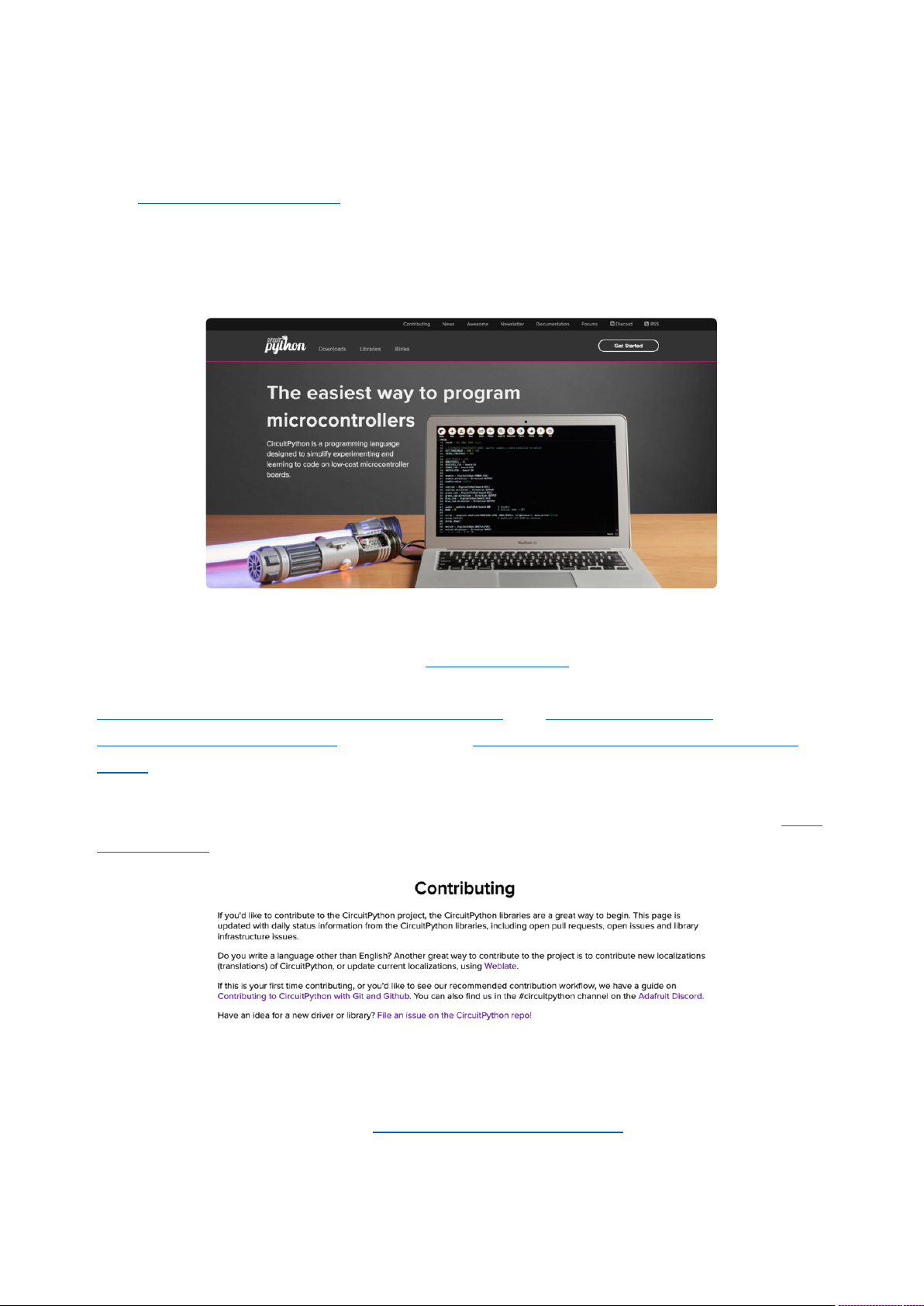
The Adafruit Discord is the 24x7x365 hackerspace that you can bring your
granddaughter to.
Visit https://adafru.it/discord ()to sign up for Discord. Everyone is looking forward to
meeting you!
CircuitPython.org
Beyond the Adafruit Learn System, which you are viewing right now, the best place to
find information about CircuitPython is circuitpython.org(). Everything you need to get
started with your new microcontroller and beyond is available. You can do things like
download CircuitPython for your microcontroller() or download the latest
CircuitPython Library bundle(), or check out which single board computers support
Blinka(). You can also get to various other CircuitPython related things like Awesome
CircuitPython or the Python for Microcontrollers newsletter. This is all incredibly
useful, but it isn't necessarily community related. So why is it included here? The Cont
ributing page().
CircuitPython itself is written in C. However, all of the Adafruit CircuitPython libraries
are written in Python. If you're interested in contributing to CircuitPython on the
Python side of things, check out circuitpython.org/contributing(). You'll find
information pertaining to every Adafruit CircuitPython library GitHub repository, giving
you the opportunity to join the community by finding a contributing option that works
for you.
©Adafruit Industries Page 100 of 199
 Loading...