

Page 1

QT Py Heart Shaped NeoPixel PCB
Created by Ruiz Brothers
Last updated on 2021-02-15 10:26:23 AM EST
Page 2

2
3
4
6
7
7
7
8
8
8
9
9
9
9
9
10
11
11
12
12
12
12
13
13
13
13
15
15
15
15
16
16
17
17
20
20
20
22
22
22
22
23
23
24
24
24
24
25
25
25
Guide Contents
Guide Contents
Overview
Parts
CNC Milling Parts & Supplies
Designing the PCB
Software
QT Py Footprint
NeoPixel Footprint
Board Shape
Traces and Spaces
PCB Service
Design File
Upload to OSHPark
Board Upload
Verify Board
Submit Order
Milling PCBs
FR-1 Single-sided PCBs
Double-sided Tape
Secure to Spoilboard
Endmill with the Fan Bit
Otherpan
Start Milling
Remove PCBs
Clean PCBs
Finished PCBs
Soldering the SPI Flash Chip
2MB SPI Flash
Orient the Flash Chip
Solder the Flash Chip
Soldered Flash
Voltage and Ground Pads
CircuitPython
Set up CircuitPython Quick Start!
Code
Install Libraries
Upload Code
Solder QT Py
QT Py
SMD QT Py
Position
Solder QT Py Pads
Inspect Pads
Solder NeoPixels
NeoPixel Placement
Solder NeoPixel
Continue Soldering
Inspect Pads
USB-C Power
Finished Build
© Adafruit Industries https://learn.adafruit.com/qtpy-heart-pcb Page 2 of 26
Page 3
Overview
Create a heart-felt NeoPixel LED badge using Adafruit's QT
Py development board. This is cute project was created for
makers getting started with SMD soldering.
This singled-sided PCB features SMD pads for six 5050
NeoPixel LEDs and the Adafruit QT Py. The center cutout
allows a SPI flash chip to fit through the board. It's simple,
easy to assemble and customizable.
Use a desktop CNC to mill your custom PCBs using FR-1
blanks. You can fit up to four QT Py heart PCBs on a 4x5in
PCB blank in less than 10 minutes!
Use a PCB service like OSHPark to create custom PCBs with beautiful solder mask and silkscreen.
Download the CAD file and upload it to have them shipped to you.
Parts
Your browser does not support the video tag.
Adafruit QT Py - SAMD21 Dev Board with STEMMA QT
What a cutie pie! Or is it... a QT Py? This diminutive dev board comes with our favorite lil chip, the SAMD21
(as made famous in our GEMMA M0 and Trinket M0 boards).For...
$6.00
© Adafruit Industries https://learn.adafruit.com/qtpy-heart-pcb Page 3 of 26
Page 4
In Stock
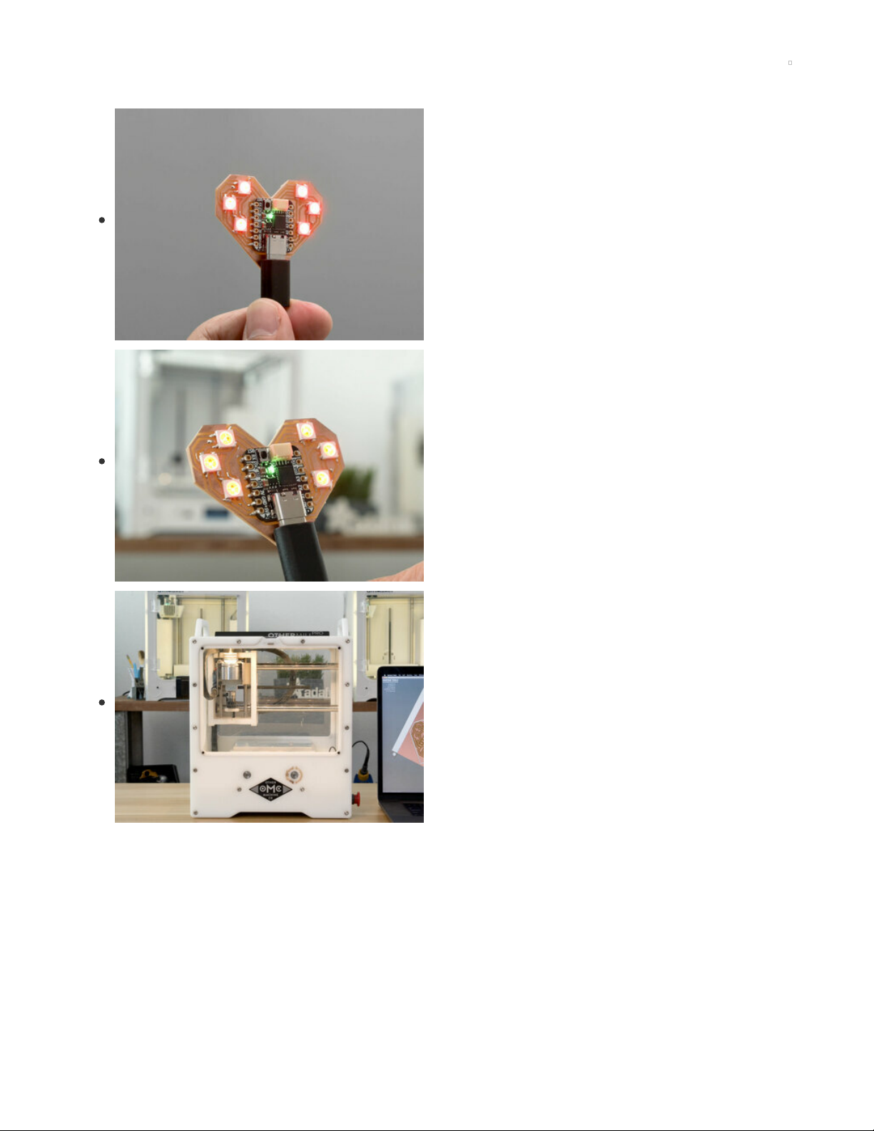
GD25Q16 - 2MB SPI Flash in 8-Pin SOIC package
These little chips are like miniature SSD drives for your electronics. When you don't need something with
as much storage as a micro SD card, but an EEPROM is too small, SPI (or...
$1.25
In Stock
Add to Cart
Add to Cart
© Adafruit Industries https://learn.adafruit.com/qtpy-heart-pcb Page 4 of 26
Page 5
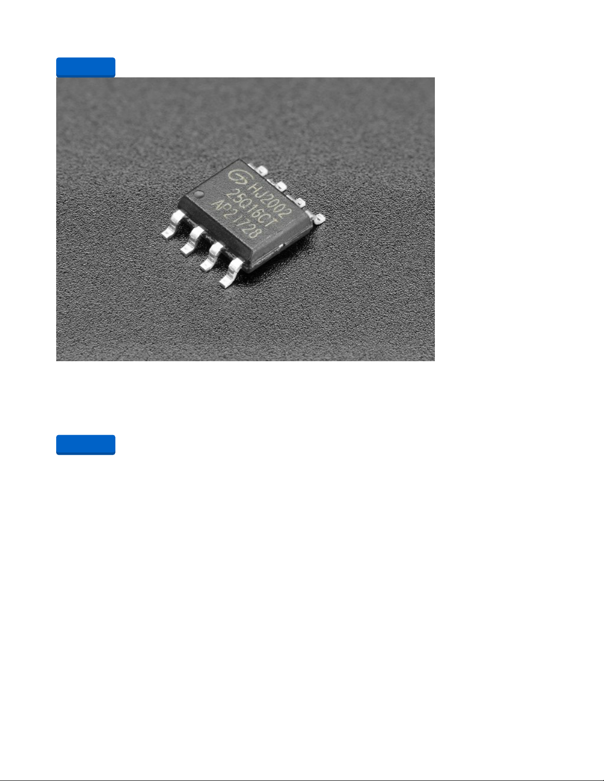
NeoPixel 5050 RGB LED with Integrated Driver Chip - 10 Pack
Make your own smart LED arrangement with the same integrated LED that is used in our NeoPixel strip
and pixels. This tiny 5050 (5mm x 5mm) RGB LED is fairly easy to solder and is the...
$4.50
In Stock
1 x Stickvise PCB Vise
Stickvise PCB Vise
1 x Solder Wire
Solder Wire - 60/40 Rosin Core
1 x Soldering Iron
Hakko FX-888D
1 x USB-C Cable
USB Type A to Type C Cable - 6" long
CNC Milling Parts & Supplies
If you'd like to use a desktop CNC to create the PCB, you can get the build materials and tools below.
1 x Bantamtools PCB Milling Machine
Desktop CNC
Add to Cart
Add to Cart
Add to Cart
Add to Cart
Add to Cart
Buy Now
© Adafruit Industries https://learn.adafruit.com/qtpy-heart-pcb Page 5 of 26
Page 6

1 x FR-1 Single-sided PCB Blanks
Pack of 25
1 x 1/32in Flatend Mill
2-Flute flat end mill
1 x Scotch Brite Scuff Pads
Scuff Pads
Buy Now
Buy Now
Buy Now
© Adafruit Industries https://learn.adafruit.com/qtpy-heart-pcb Page 6 of 26
Page 7
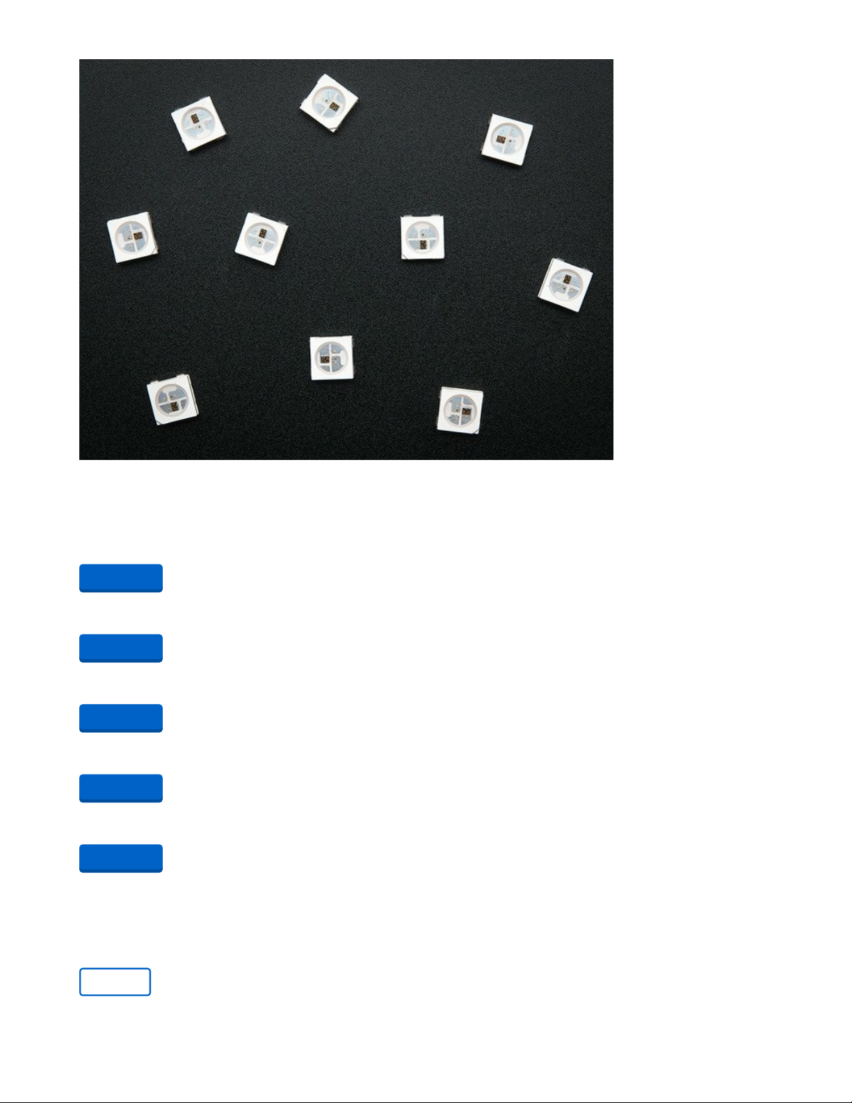
Designing the PCB
Software
This was created using Autodesk EAGLE. The PCB features custom footprints for the NeoPixels and QT
Py. Feel free to use them in your projects.
https://adafru.it/zBt
https://adafru.it/QrD
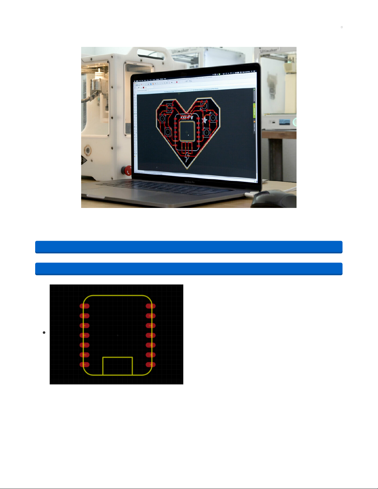
QT Py Footprint
The QT Py board features 2x7 (14 total) pins that are spaced
apart 0.1in. The two rows of pins are spaced apart 0.675in.
The SMD pads are 0.1 x 0.05in. This features an outline of the
board on the silkscreen layer to help with placement. The
rectangular outline represents the USB-C port on the QTPY.
https://adafru.it/zBt
https://adafru.it/QrD
© Adafruit Industries https://learn.adafruit.com/qtpy-heart-pcb Page 7 of 26
Page 8
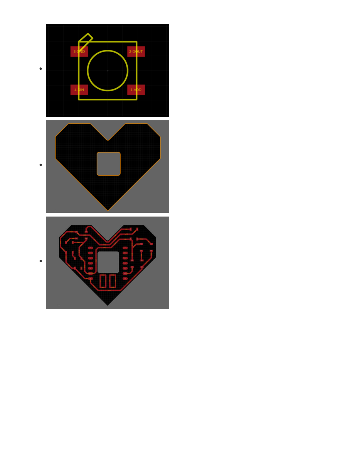
NeoPixel Footprint
The NeoPixel 5050 LEDs feature four SMD pads that are
0.05 x 0.03in. The pads are spaced apart 5 x 3.4mm. Check
the SK6812 datasheet (https://adafru.it/uaS) for referencing
the technical drawing. The outline of the NeoPixel LED
features a corner marker to note the ground pad.
Board Shape
The heart was creating using the line tool. The grid was set to
be millimeters which helps to visually draw the shape and
make it symmetrical. The size was tweaked several times to
accommodate space for the QT Py, NeoPixels and traces.
Traces and Spaces
Traces were set to 0.6in width with 0.6in of minimum spacing.
This optimizes the traces for a 1/32in flat end mill. Using a
single tool can help speed up the milling process.
Reference the design considerations
guide (https://adafru.it/BCu) on Bantamtools site for more info.
© Adafruit Industries https://learn.adafruit.com/qtpy-heart-pcb Page 8 of 26
Page 9

PCB Service
Design File
Use link below to download the .brd and .sch files for
Autodesk Eagle.
https://adafru.it/QrE
Upload to OSHPark
Unzip the file and upload the .brd file to oshpark.com (https://adafru.it/e2G).
Board Upload
The failure warning appears due to a missing drill file. It's not
required. Check the box to approve and click continue.
Verify Board
Take a moment to review each of the layers. Read through
the descriptions and take a look at the render images. If
everything looks good, click continue.
https://adafru.it/QrE
© Adafruit Industries https://learn.adafruit.com/qtpy-heart-pcb Page 9 of 26
Page 10

Submit Order
Review the quantity, minimum of 3 boards. Check out the
additional options if you'd like. Click Checkout to submit your
order.
© Adafruit Industries https://learn.adafruit.com/qtpy-heart-pcb Page 10 of 26
Page 11

Milling PCBs
These PCBs were made with the desktop CNC from Bantam Tools. The
otherplan (https://adafru.it/IVC) software (https://adafru.it/IVC) because you can easily drag and drop your
cad files. We designed the PCB in Autodesk Eagle and created a custom footprint for the QT Py. This was
routed for a single-layered board and features pretty chunky traces.
FR-1 Single-sided PCBs
These singled-sided FR-1 blanks from bantam tools are precut so they fit on the spoilboard.
© Adafruit Industries https://learn.adafruit.com/qtpy-heart-pcb Page 11 of 26
Page 12

Double-sided Tape
To secure the PCB blank to the spoilboard, you can use
double-sided scotch tape. I like to use wide tape because it
gives you more coverage – just be careful the tape doesn’t
overlap.
Secure to Spoilboard
The PCB is lined up with the lower left corner of the
spoilboard. Material can be warped so I make sure to press
down firmly and wipe the surface clean.
Endmill with the Fan Bit
The 1/32 inch flat end mill is my go-to tool whenever I’m
milling PCBs. Using a fan bit keeps the dust away and it’s
handy if you’re doing any sort of filming.
End mills are secured to the collet and the machine has a
probing process that checks the tool z-height.
Otherpan
Four QT Py Heart PCBs fit on one sheet of FR-1 (127mm x
101mm). You can get the most out of your material by placing
your boards closer together.
© Adafruit Industries https://learn.adafruit.com/qtpy-heart-pcb Page 12 of 26
Page 13

Start Milling
After going through your internal checklist, "Get Ready to
Start Milling!"
Remove PCBs
Use alcohol to soften up the adhesive from the tape. A squirt
bottle is great for applying to the spoilboard.
Use a thin spatula or palette knife to pry the FR-1 sheet off the
spoilboard. Ideally remove the whole PCB from the
spoilboard in one piece.
Clean PCBs
Wipe the PCBs clean with alcohol using paper towels. Use
Scotch Brite scuff pads to lightly sand the edges and surface.
Finished PCBs
After some clean up, the PCB’s came out really nice. All four
of these came out pretty clean, so we can get them ready for
soldering. They only took about 10 minutes to machine, which
is pretty impressive.
© Adafruit Industries https://learn.adafruit.com/qtpy-heart-pcb Page 13 of 26
Page 14

© Adafruit Industries https://learn.adafruit.com/qtpy-heart-pcb Page 14 of 26
Page 15

Soldering the SPI Flash Chip
2MB SPI Flash
First, let’s get the 2MB SPI flash chip soldered to the back of
the QT Py PCB.
Orient the Flash Chip
Use the marker on the solder mask to get the first pins
oriented correctly.
Solder the Flash Chip
Tin one of the pads with solder. Using tweezers, position the
chip over the tinned pad. Heat up the solder with the tip of
the iron. While the solder is molten, reposition the chip into
place with tweezers.
© Adafruit Industries https://learn.adafruit.com/qtpy-heart-pcb Page 15 of 26
Page 16

Soldered Flash
Continue to solder each pad by adding a bit of solder to the
tip of the iron and adding it to the leg of the chip. Inspected
pads after soldering.
Voltage and Ground Pads
The power and ground pads on the back of the QT Py PCB
should be insulated with Kapton tape to avoid shorting
anything out.
© Adafruit Industries https://learn.adafruit.com/qtpy-heart-pcb Page 16 of 26
Page 17

CircuitPython
CircuitPython (https://adafru.it/tB7) is a derivative of MicroPython (https://adafru.it/BeZ) designed to
simplify experimentation and education on low-cost microcontrollers. It makes it easier than ever to get
prototyping by requiring no upfront desktop software downloads. Simply copy and edit files on the
CIRCUITPY drive to iterate.
Set up CircuitPython Quick Start!
Follow this quick step-by-step for super-fast Python power :)
If you want to get started with your QT Py, and you have NOT soldered a chip to the back of it, download
CircuitPython from the following link:
https://adafru.it/NCB
If you have soldered a GD25Q16 SPI flash chip to the bottom of your board, you must use the
Haxpress version of CircuitPython for the Adafruit QT Py for the flash to work! If you have NOT
soldered a SPI flash chip to your QT Py, do NOT use this download! It will not give you 2MB of flash
space without a chip!
https://adafru.it/NCC
Click the link above and download the latest UF2 file.
Download and save it to your desktop (or wherever is handy).
https://adafru.it/NCB
https://adafru.it/NCC
© Adafruit Industries https://learn.adafruit.com/qtpy-heart-pcb Page 17 of 26
Page 18

Plug your QT Py into your computer using a known-good USB
cable.
A lot of people end up using charge-only USB cables and it
is very frustrating! So make sure you have a USB cable you
know is good for data sync.
Double-click the small RST (reset) button, and you will see
the NeoPixel RGB LED turn green. If it turns red, check the
USB cable, try another USB port, etc.
If double-clicking doesn't work the first time, try again.
Sometimes it can take a few tries to get the rhythm right!
You will see a new disk drive appear called QTPY_BOOT.
Drag the adafruit_circuitpython_etc.uf2 file to QTPY_BOOT
The red LED will flash. Then, the QTPY_BOOT drive will
disappear and a new disk drive called CIRCUITPY will
appear.
That's it, you're done! :)
© Adafruit Industries https://learn.adafruit.com/qtpy-heart-pcb Page 18 of 26
Page 19

© Adafruit Industries https://learn.adafruit.com/qtpy-heart-pcb Page 19 of 26
Page 20

Code
Take your QT Py and plug it into your computer via a known good data + power USB cable. Your
operating system will show a drive named CIRCUITPY when a board is plugged in. If you get a drive
named QTPY_BOOT you'll likely need to install CircuitPython.
The QT Py with the SPI flash memory chip is called the "QT Py Haxpress" and uses different CircuitPython
firmware from CircuitPython.org if you need to reflash it.
Adafruit CircuitPython 6.1.0 on 2021-01-21; Adafruit QT Py M0 Haxpress with samd21e18
Install Libraries
You'll need a few CircuitPython libraries in the lib folder on the Feather CIRCUITPY drive for the code to
work. Head to https://circuitpython.org/libraries (https://adafru.it/ENC) to download the latest library
bundle matching the major version of CircuitPython now on your board (6 for CircuitPython 6.x, etc.).
Once you've downloaded the libraries bundle, add these libraries to the lib folder on the Feather:
adafruit_led_animation
neopixel.mpy
Your QT Py CIRCUITPY drive should look like this after you load the code below.:
Upload Code
Once your QT Py is all setup with CircuitPython and the necessary libraries, you can click on
the Download: Project Zip link below the code to get the files.
© Adafruit Industries https://learn.adafruit.com/qtpy-heart-pcb Page 20 of 26
Page 21

import board
import neopixel
from adafruit_led_animation.animation.pulse import Pulse
from adafruit_led_animation.color import RED
# Update to match the pin connected to your NeoPixels
pixel_pin = board.D1
# Update to match the number of NeoPixels you have connected
pixel_num = 6
pixels = neopixel.NeoPixel(pixel_pin, pixel_num, brightness=0.5, auto_write=False)
pulse = Pulse(pixels, speed=0.01, color=RED, period=1)
while True:
pulse.animate()
© Adafruit Industries https://learn.adafruit.com/qtpy-heart-pcb Page 21 of 26
Page 22

Solder QT Py
QT Py
Get the QT Py ready to solder onto the Heart PCB.
Castellated pads on the QT Py make it easy to surface mount.
SMD QT Py
Secure the Heart PCB to a stickvise and placed the QT Py
PCB on top in the center.
Position
Check the pads on both sides so they fit evenly spaced apart.
© Adafruit Industries https://learn.adafruit.com/qtpy-heart-pcb Page 22 of 26
Page 23

Solder QT Py Pads
Place the tip of the iron on the side and add solder. Start by
tinning the tip of the iron and add it to one pad using
tweezers to keep it in place. After the first pad is soldered,
the rest gets easier.
Inspect Pads
To get the most mechanical strength, flood the through-hole
pins with solder. Thoroughly check the solder joints are fully
touching the pads.
© Adafruit Industries https://learn.adafruit.com/qtpy-heart-pcb Page 23 of 26
Page 24

Solder NeoPixels
NeoPixel Placement
Reference the board design in Eagle by either screenshot or
print out. Place the first NeoPixel using the corner marker to
note the ground pin.
Solder NeoPixel
Tin the tip of the iron with a bit of solder. While holding the
NeoPixel in place with tweezers, add solder to one of the
pads. Once one pad is anchored, the rest gets easier to
solder.
Continue Soldering
Reflow pads if needed and make sure to clean the tip of the
iron with a brass sponge frequently.
© Adafruit Industries https://learn.adafruit.com/qtpy-heart-pcb Page 24 of 26
Page 25

Inspect Pads
Throughly inspect the four pads on each pixel.
USB-C Power
Get the PCB ready to test once all of the pixels have been
soldered.
You can use a 5V USB battery to power the QT Py with a
USB-C cable.
Finished Build
If everything lights up, congrats! SMD soldering skill leveled up, woohoo!
© Adafruit Industries https://learn.adafruit.com/qtpy-heart-pcb Page 25 of 26
Page 26

© Adafruit Industries Last Updated: 2021-02-15 10:26:23 AM EST Page 26 of 26
 Loading...