

Page 1
LSM6DSOX, ISM330DHC, and LSM6DSO32 6 DoF IMUs
Created by Bryan Siepert
Last updated on 2020-09-22 01:12:00 PM EDT
Page 2
Overview
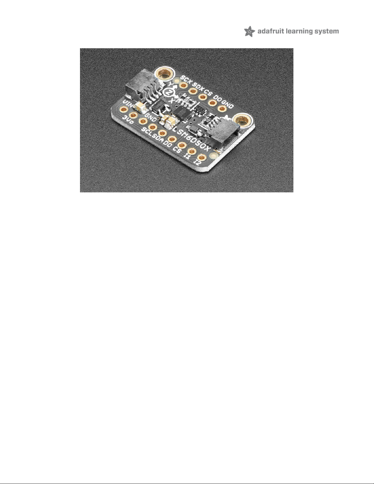
Behold, the ST LSM6DSOX: The latest in a long line of quality Accelerometer+Gyroscope 6-DOF IMUs from ST. Along
with the LSM6DSOX, this guide will cover the
industrial
version, the ISM330DHCX and their wider range sibling the
LSM6DSO32. All are pin-compatible and are nearly code-compatible - we'll be using the same library code and wiring
diagrams to connect to both
In the ISM330DHCX the sensing elements of the accelerometer and of the gyroscope are implemented on the same
silicon die, thus guaranteeing superior stability and robustness. It also has an extended temperature range of -40 to
+105 °C compared to the LSM6DSOX's -40 to +85 °C. Finally, the ISM330's gyroscope can measure up to ±4000 dps,
the LSM6DSOX tops out at ±2000 dps. If those extras aren't essential for your needs, the LSM6DSOX will do quite
nicely.
Should you wish for a wider range of acceleration measurement, the LSM6DSO32 will have you covered. Compared to
the +/-2 to +/- 16g , the LSM6DSO32 can measure higher acceleration amounts and is configurable from +/- 4-32g! This
will allow for capturing more extreme motion events.
© Adafruit Industries https://learn.adafruit.com/lsm6dsox-and-ism330dhc-6-dof-imu Page 3 of 21
Page 3
All three sensors are great IMU sensors with 6 degrees of freedom - 3 degrees each of linear acceleration and angular
velocity at varying rates within a respectable range.
For the LSM6DSOX and ISM330DHCX, the accelerometers have a respectable range of: ±2/±4/±8/±16 g at 1.6 Hz to
6.7KHz update rate. The LSM6DSO32's accelerometers can measure ±4/±8/±16±32 at the cost of a bit of additional
noise in the signal.
For the gyroscopes: ±125/±250/±500/±1000/±2000 dps (plus ±4000 dps for the ISM330) at 12.5 Hz to 6.7 KHz. There's
also some nice extras, such as built in tap detection, activity detection, pedometer/step counter and in the LSM6DSOX
and ISM330DHCX a programmable finite state machine / machine learning core that can perform some basic gesture
recognition.
For interfacing, you can use either SPI or I2C - there's two configurable interrupt pins. For advanced usage, you can
attach additional devices to an external I2C/SPI port - used for optical image stabilization.
To make getting started fast and easy, we placed the sensors on compact breakout boards with voltage regulation and
level-shifted inputs. That way you can use them with 3V or 5V power/logic devices without worry.
We also wrote libraries to help you get these sensors integrated with your Arduino/C++ or CircuitPython/Python boards
such as Raspberry Pi or other single board computers.
© Adafruit Industries https://learn.adafruit.com/lsm6dsox-and-ism330dhc-6-dof-imu Page 4 of 21
Page 4
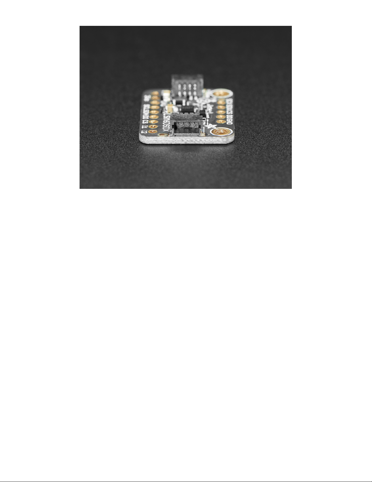
Additionally since it speaks I2C you can easily connect it up with two wires (plus power and ground!). We've even
included SparkFun qwiic (https://adafru.it/Fpw) compatible STEMMA QT (https://adafru.it/Ft4) connectors for the I2C
bus so you don't even need to solder! Just wire up to your favorite micro with a plug-and-play cable to get 6 DoF data
ASAP.
© Adafruit Industries https://learn.adafruit.com/lsm6dsox-and-ism330dhc-6-dof-imu Page 5 of 21
Page 5
Pinouts
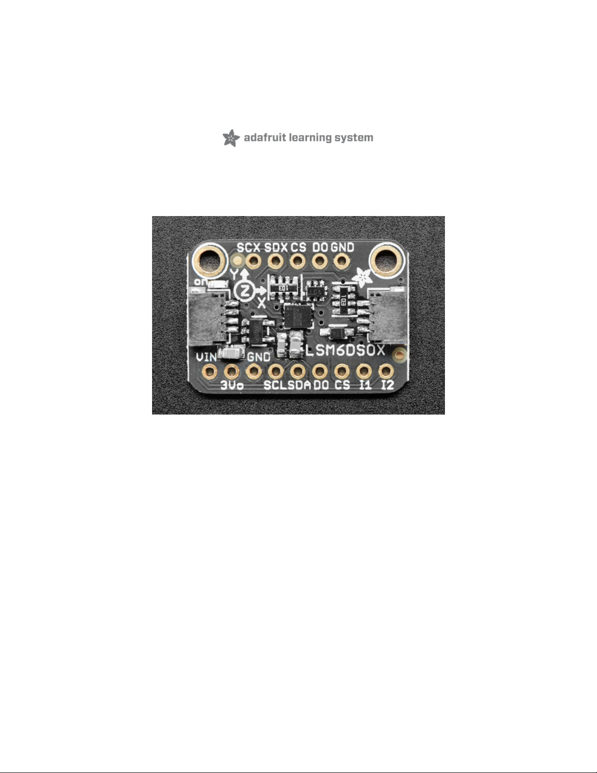
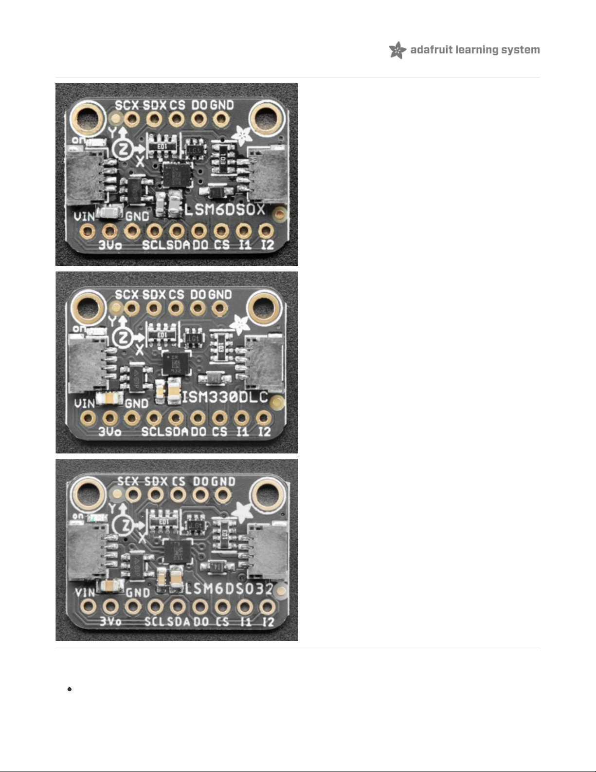
The top of each breakout is very similar! They include
The names of all the pins which you can reference in
the lists below
Power Pins
Vin - this is the power pin. Since the sensor chip uses 3 VDC, we have included a voltage regulator on board that
© Adafruit Industries https://learn.adafruit.com/lsm6dsox-and-ism330dhc-6-dof-imu Page 6 of 21
Page 6

will take 3-5VDC and safely convert it down. To power the board, give it the same power as the logic level of
your microcontroller - e.g. for a 5V microcontroller like Arduino, use 5V
3Vo - this is the 3.3V output from the voltage regulator, you can grab up to 100mA from this if you like
GND - common ground for power and logic
I2C Logic Pins
SCL - I2C clock pin, connect to your microcontroller's I2C clock line. This pin is level shifted so you can use 3-5V
logic, and there's a 10K pullup on this pin.
SDA -I2C data pin, connect to your microcontroller's I2C data line. This pin is level shifted so you can use 3-5V
logic, and there's a 10K pullup on this pin.
STEMMA QT (https://adafru.it/Ft4) - These connectors allow you to connectors to dev boards with STEMMA QT
connectors or to other things with various associated accessories (https://adafru.it/Ft6)
SPI Logic pins:
All pins going into the breakout have level shifting circuitry to make them 3-5V logic level safe. Use whatever logic
level is on Vin!
SCK - This is
also
the SPI Clock pin, it's an input to the chip
DO (Bottom) - this is the serial Data Out / Microcontroller In Sensor Out pin, for data sent from the LSM6DSOX,
ISM330DHCX, or LSM6DSO32 to your processor.
SDA - this is
also
the Serial Data In / Microcontroller Out Sensor In pin, for data sent from your processor to the
LSM6DSOX, ISM330DHCX, or LSM6DSO32
CS (Bottom) - this is the Chip Select pin, drop it low to start an SPI transaction. Its an input to the chip
If you want to connect multiple LSM6DSOX, ISM330DHCX, or LSM6DSO32's to one microcontroller, have them share
the SDI, DO and SCK pins. Then assign each one a unique CS pin.
Other Pins
INT1 -This is the primary interrupt pin. You can setup the LSM6DSOX, ISM330DHCX, or LSM6DSO32 to pull this
low when certain conditions are met such as new measurement data being available. Consult the
datasheet (https://adafru.it/HFU) for usage
INT2 -This is the primary interrupt pin. You can setup the LSM6DSOX, ISM330DHCX, or LSM6DSO32 to pull this
low when certain conditions are met such as new measurement data being available. Consult the
datasheet (https://adafru.it/HFU) for usage
D0 (Bottom) - I2C Address pin. Pulling this pin high or bridging the solder jumper on the back will change the I2C
address from 0x6A to 0x6B
SCX, SDX, Aux CS, DO (Top) - Pins for advanced users to connect the LSM6DSOX, ISM330DHCX, or
LSM6DSO32 to another sensor. Consult the datasheet (https://adafru.it/HFU) for usage
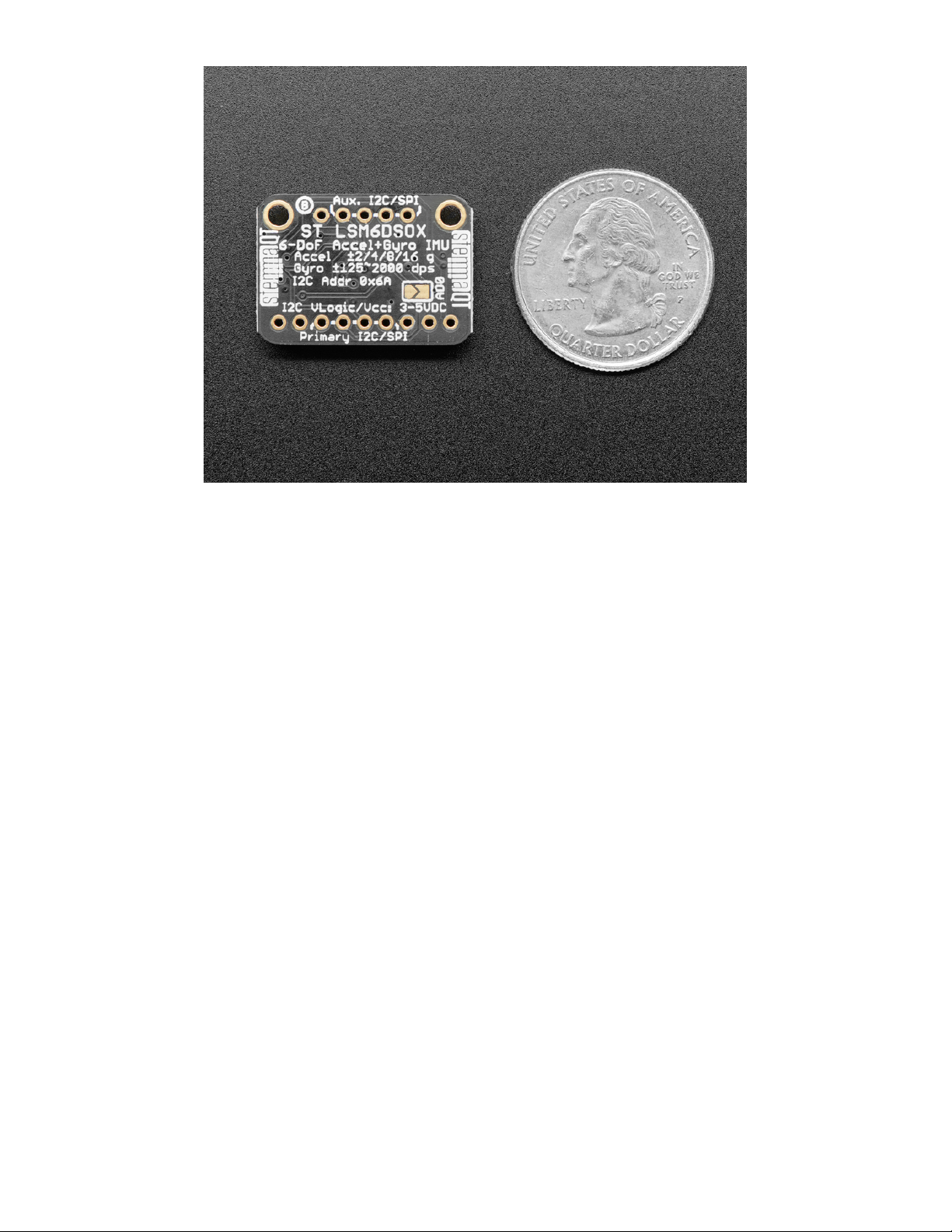
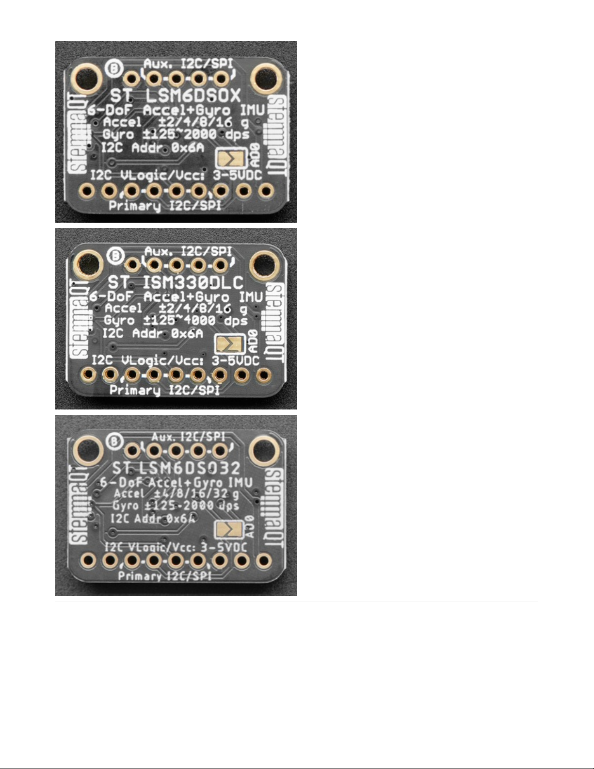
The backs of the breakouts show additional information
about the specifications of the sensor, as well as the I2C
address and additional pin information
© Adafruit Industries https://learn.adafruit.com/lsm6dsox-and-ism330dhc-6-dof-imu Page 7 of 21
Page 7
© Adafruit Industries https://learn.adafruit.com/lsm6dsox-and-ism330dhc-6-dof-imu Page 8 of 21
Page 8
Arduino
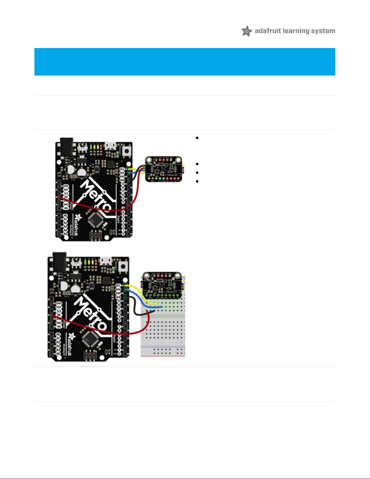
I2C Wiring
Use this wiring if you want to connect via I2C interface
By default, theI2C address is 0x6A. If you add a jumper from DO to 3.3V the address will change to 0x6B
Connect board VIN (red wire) to Arduino 5V if
you are running a 5V board Arduino (Uno, etc.). If
your board is 3V, connect to that instead.
Connect board GND (black wire) to Arduino GND
Connect board SCL (yellow wire) to Arduino SCL
Connect board SDA (blue wire) to Arduino SDA
The final results should resemble the illustration above, showing an Adafruit Metro development board.
SPI Wiring
Since this is a SPI-capable sensor, we can use hardware or 'software' SPI. To make wiring identical on all
microcontrollers, we'll begin with 'software' SPI. The following pins should be used:
Because they share the same pinout and I2C address, the examples below can be used for the LSM6DSOX,
ISM330DHX, and LSM6DSO32
© Adafruit Industries https://learn.adafruit.com/lsm6dsox-and-ism330dhc-6-dof-imu Page 9 of 21
Page 9
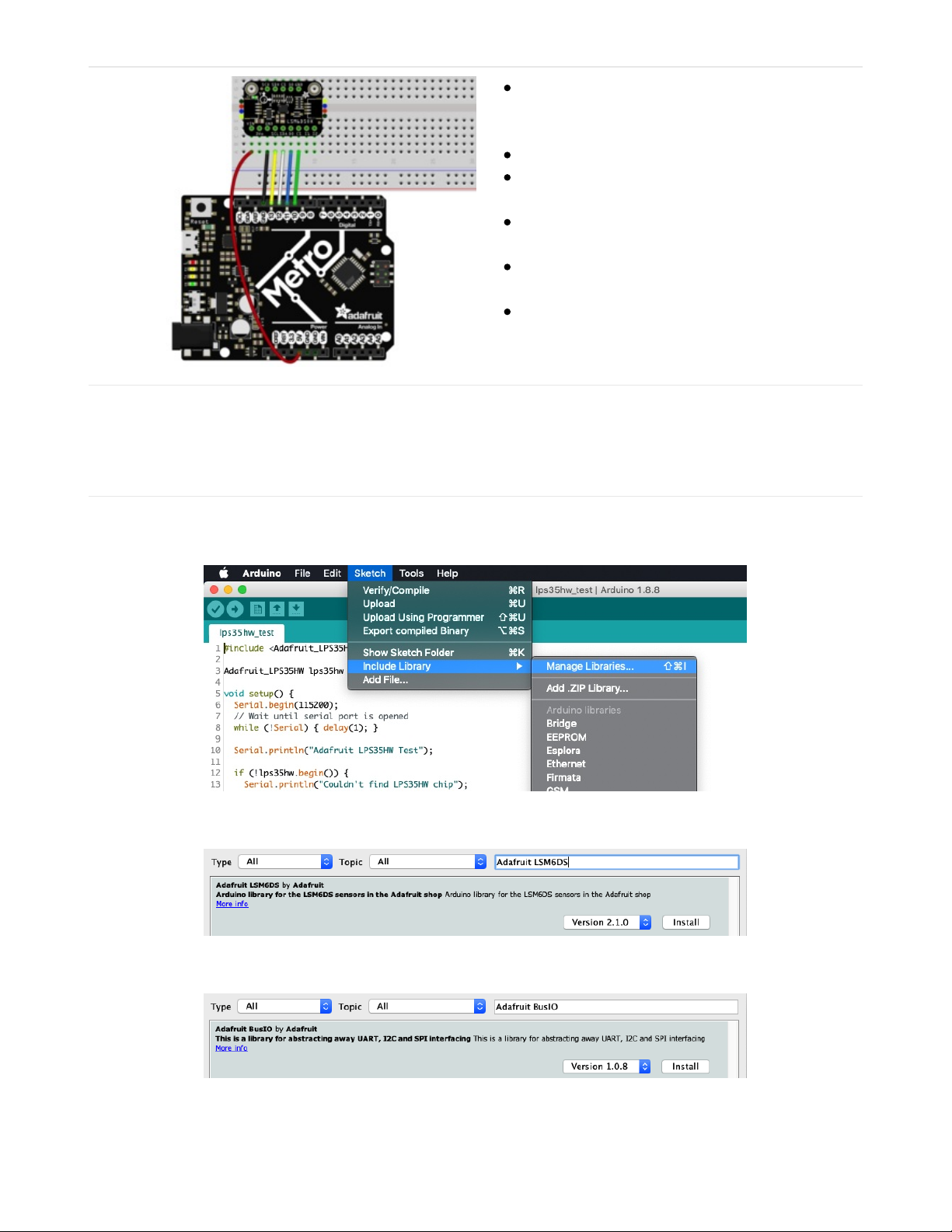
Connect Vin to the power supply, 3V or 5V is fine.
Use the same voltage that the microcontroller
logic is based off of
Connect GND to common power/data ground
Connect the SCL pin to Digital #13 but any pin can
be used later
Connect the DO pin to Digital #12 but any pin can
be used later
Connect the SDA pin to Digital #11 but any pin can
be used later
Connect the CS pin Digital #10 but any pin can be
used later
Later on, once we get it working, we can adjust the library to use hardware SPI if you desire, or change the pins to
others.
Library Installation
You can install the Adafruit LSM6DS Library for Arduino using the Library Manager in the Arduino IDE. This will work
for the LSM6DSOX, ISM330DHCX, LSM6DSO32, and even the LSM6DS33:
Click the Manage Libraries ... menu item, search for Adafruit LSM6DS, and select the Adafruit LSM6DS library:
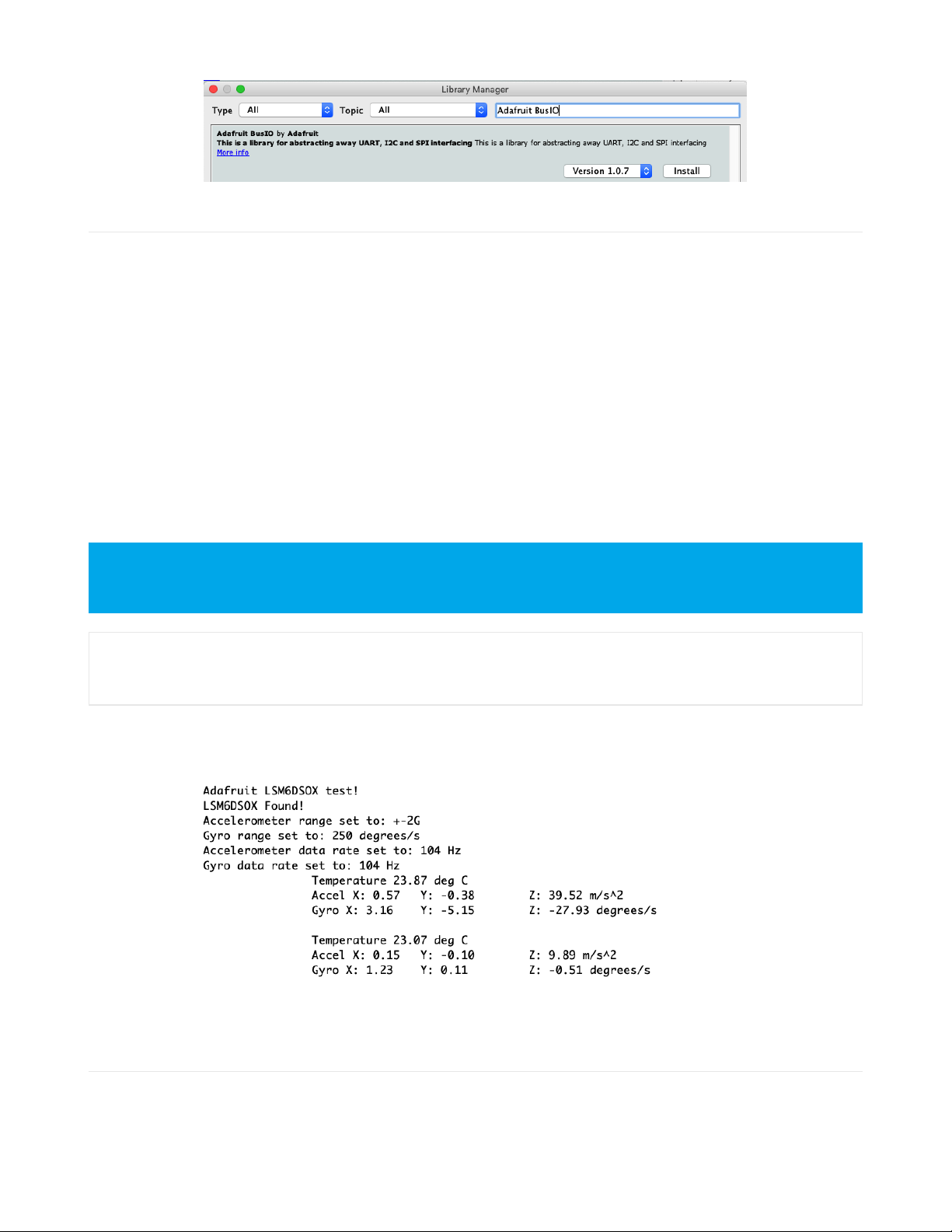
Then follow the same process for the Adafruit BusIO library.
Finally follow the same process for the Adafruit Unified Sensor library:
© Adafruit Industries https://learn.adafruit.com/lsm6dsox-and-ism330dhc-6-dof-imu Page 10 of 21
Page 10
Load Example - LSM6DSOX, ISM330DHCX, or LSM6DSO32
The library includes different examples for each of the sensors it supports, so you will need to select the correct one.
If you are using an LSM6DSOX, open up File -> Examples -> Adafruit LSM6DS -> adafruit_lsm6dsox_test and upload
to your Arduino wired up to the sensor.
If you are using an ISM330DHCX, open up File -> Examples -> Adafruit LSM6DS -> adafruit_ism330dhcx_test and
upload to your Arduino wired up to the sensor.
If you are using an LSM6DSO32, open up File -> Examples -> Adafruit LSM6DS -> adafruit_lsm6dso32_test and
upload to your Arduino wired up to the sensor.
Depending on whether you are using I2C or SPI, change the pin names and comment or uncomment the following
lines.
if (!lsm6dsox.begin_I2C()) {
//if (!lsm6dsox.begin_SPI(LPS_CS)) {
//if (!lsm6dsox.begin_SPI(LPS_CS, LPS_SCK, LPS_MISO, LPS_MOSI)) {
Once you upload the code, you will see the accelerometer, gyro, and temperature measurements being printed when
you open the Serial Monitor (Tools->Serial Monitor) at 115200 baud, similar to this:
Give the sensor a wiggle or a spin and watch how the measurements change!
Example Code - LSM6DSOX
Note that the code snippet and screenshot below are from the LSM6DSOX example. The ISM330DHCX and
LSM6DSO32 examples will be similar but not identical
© Adafruit Industries https://learn.adafruit.com/lsm6dsox-and-ism330dhc-6-dof-imu Page 11 of 21
Page 11

Temporarily unable to load content:
Example Code - ISM330DHCX
Temporarily unable to load content:
Example Code - LSM6DSO32
Temporarily unable to load content:
© Adafruit Industries https://learn.adafruit.com/lsm6dsox-and-ism330dhc-6-dof-imu Page 12 of 21
Page 12

Arduino
Docs
Arduino Docs (https://adafru.it/IAQ)
© Adafruit Industries https://learn.adafruit.com/lsm6dsox-and-ism330dhc-6-dof-imu Page 13 of 21
Page 13
Python & CircuitPython
It's easy to use the LSM6DSOX or ISM330DHCX sensors with Python and CircuitPython, and the Adafruit CircuitPython
LSM6DS (https://adafru.it/Iec) module. This module allows you to easily write Python code that reads measurements
from the accelerometer and gyro, and will work with either sensor.
You can use this sensor with any CircuitPython microcontroller board or with a computer that has GPIO and Python
thanks to Adafruit_Blinka, our CircuitPython-for-Python compatibility library (https://adafru.it/BSN).
CircuitPython Microcontroller Wiring
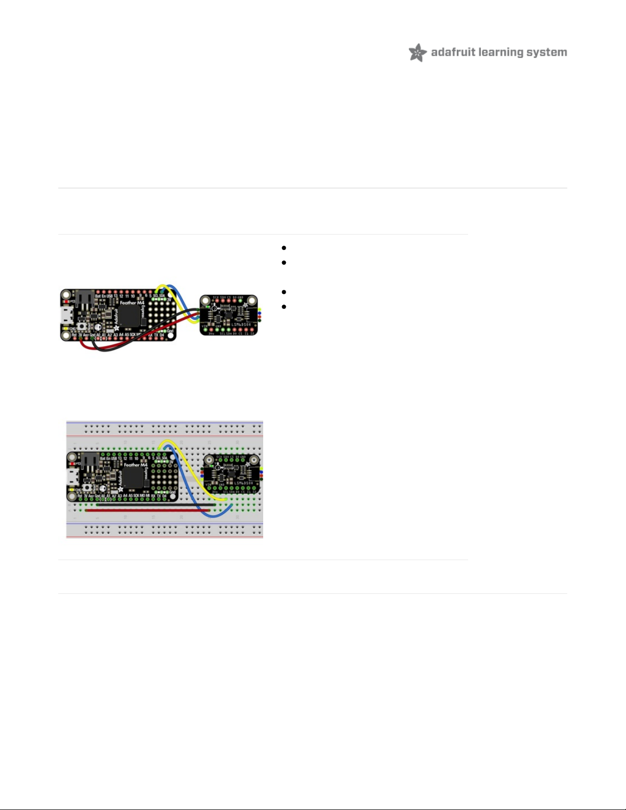
First wire up a LSM6DSOX or ISM330DHCX to your board for an I2C connection, exactly as shown below. Here's an
example of wiring a Feather M4 to the sensor with I2C:
Board 3V to sensor VIN (red wire)
Board GND to sensor GND (black
wire)
Board SCL to sensor SCL (yellow wire)
Board SDA to sensor SDA (blue wire)
Python Computer Wiring
Since there's
dozens
of Linux computers/boards you can use we will show wiring for Raspberry Pi. For other platforms,
please visit the guide for CircuitPython on Linux to see whether your platform is supported (https://adafru.it/BSN).
Here's the Raspberry Pi wired with I2C:
© Adafruit Industries https://learn.adafruit.com/lsm6dsox-and-ism330dhc-6-dof-imu Page 14 of 21
Page 14
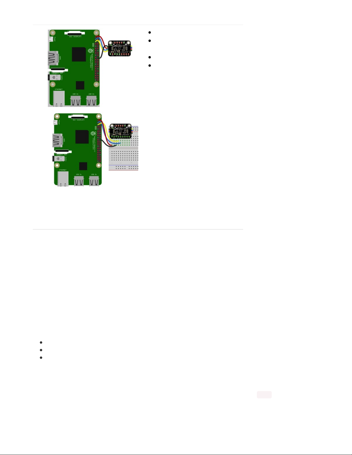
Pi 3V to sensor VCC (red wire)
Pi GND to sensor GND (black
wire)
Pi SCL to sensor SCL (yellow wire)
Pi SDA to sensor SDA (blue wire)
CircuitPython Installation of LSM6DS Library
You'll need to install the Adafruit CircuitPython LSM6DS (https://adafru.it/Iec) library on your CircuitPython board. This
library works with the LSM6DSOX, LSM6DS33, or ISM330DHCX
First make sure you are running the latest version of Adafruit CircuitPython (https://adafru.it/Amd) for your board.
Next you'll need to install the necessary libraries to use the hardware--carefully follow the steps to find and install these
libraries from Adafruit's CircuitPython library bundle (https://adafru.it/ENC). Our CircuitPython starter guide has a great
page on how to install the library bundle (https://adafru.it/ABU).
For non-express boards like the Trinket M0 or Gemma M0, you'll need to manually install the necessary libraries from
the bundle:
adafruit_lsm6ds.mpy
adafruit_bus_device
adafruit_register
Before continuing make sure your board's lib folder or root filesystem has the adafruit_lsm6ds.mpy,
adafruit_bus_device, and adafruit_register files and folders copied over.
Next connect to the board's serial REPL (https://adafru.it/Awz)so you are at the CircuitPython >>> prompt.
© Adafruit Industries https://learn.adafruit.com/lsm6dsox-and-ism330dhc-6-dof-imu Page 15 of 21
Page 15
Python Installation of LSM6DS Library
You'll need to install the Adafruit_Blinka library that provides the CircuitPython support in Python. This may also
require enabling I2C on your platform and verifying you are running Python 3. Since each platform is a little different,
and Linux changes often, please visit the CircuitPython on Linux guide to get your computer
ready (https://adafru.it/BSN)!
Once that's done, from your command line run the following command:
sudo pip3 install adafruit-circuitpython-lsm6ds
If your default Python is version 3 you may need to run 'pip' instead. Just make sure you aren't trying to use
CircuitPython on Python 2.x, it isn't supported!
CircuitPython & Python Usage
To demonstrate the usage of the sensor we'll initialize it and read the acceleration and rotation measurements from
the board's Python REPL.
Run the following code to import the necessary modules and initialize the I2C connection with the sensor:
import time
import board
import busio
import adafruit_lsm6ds
i2c = busio.I2C(board.SCL, board.SDA)
sox = adafruit_lsm6ds.LSM6DSOX(i2c)
Now you're ready to read values from the sensor using these properties:
acceleration - The acceleration forces in the X, Y, and Z axes in m/s
gyro - The rotation measurement on the X, Y, and Z axes in degrees/sec
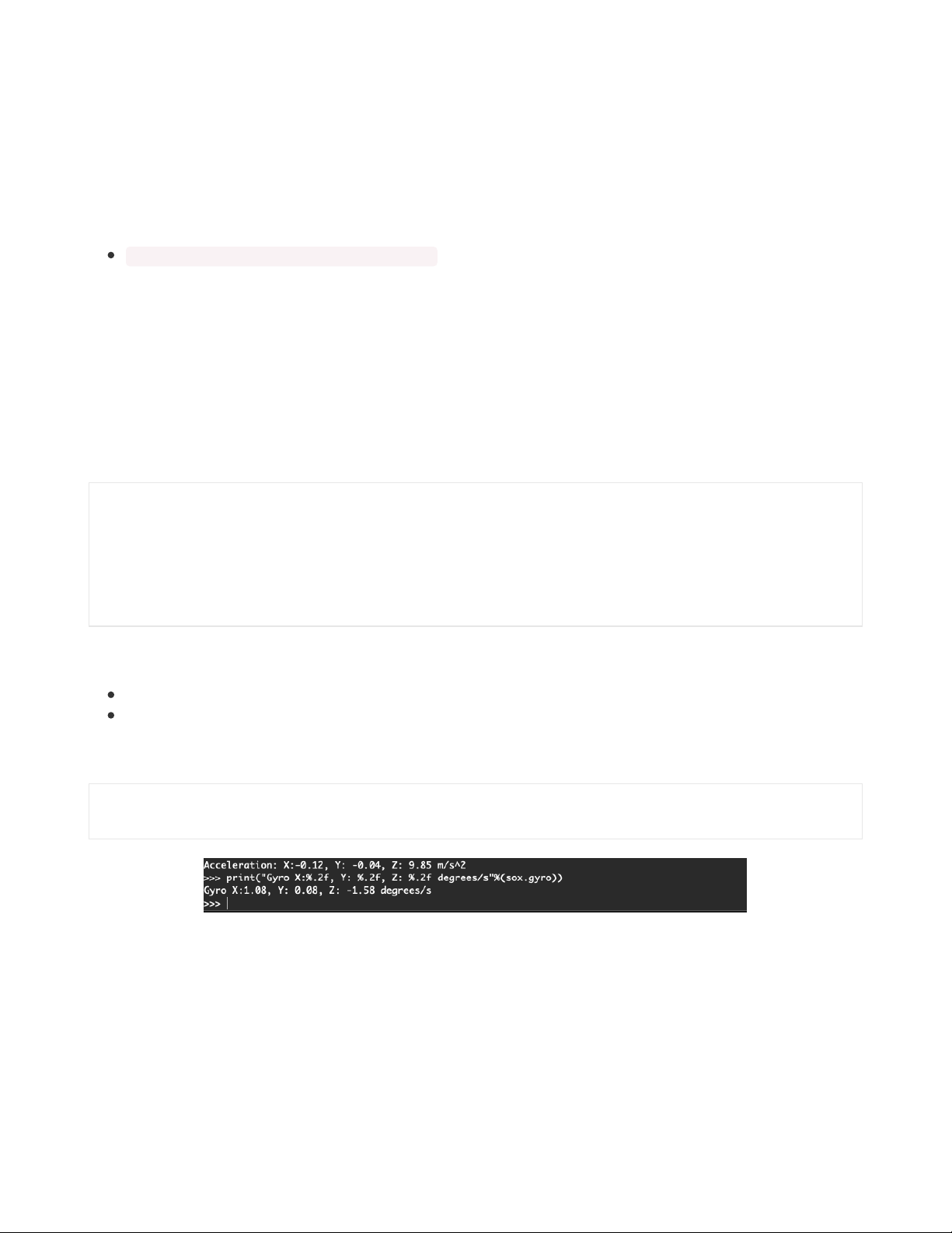
For example, to print out the acceleration and gyro measurements use this code:
print("Acceleration: X:%.2f, Y: %.2f, Z: %.2f m/s^2" % (sensor.acceleration))
print("Gyro X:%.2f, Y: %.2f, Z: %.2f degrees/s" % (sensor.gyro))
That's all there is to it! Go forth and imbue your robot friends with the gift of being able to maybe not fall down all the
time. Maybe.
Example Code
2
© Adafruit Industries https://learn.adafruit.com/lsm6dsox-and-ism330dhc-6-dof-imu Page 16 of 21
Page 16

# SPDX-FileCopyrightText: Copyright (c) 2020 Bryan Siepert for Adafruit Industries
#
# SPDX-License-Identifier: MIT
import time
import board
import busio
from adafruit_lsm6ds.lsm6dsox import LSM6DSOX
i2c = busio.I2C(board.SCL, board.SDA)
sensor = LSM6DSOX(i2c)
while True:
print("Acceleration: X:%.2f, Y: %.2f, Z: %.2f m/s^2" % (sensor.acceleration))
print("Gyro X:%.2f, Y: %.2f, Z: %.2f radians/s" % (sensor.gyro))
print("")
time.sleep(0.5)
© Adafruit Industries https://learn.adafruit.com/lsm6dsox-and-ism330dhc-6-dof-imu Page 17 of 21
Page 17

Python
Docs
Python Docs (https://adafru.it/Igb)
© Adafruit Industries https://learn.adafruit.com/lsm6dsox-and-ism330dhc-6-dof-imu Page 18 of 21
Page 18
Downloads
Files
LSM6DSOX Datasheet (https://adafru.it/HFw)
ISM330DHCX Datasheet (https://adafru.it/HFx)
LSM6DSO32 Datasheet (https://adafru.it/NwD)
EagleCAD files on GitHub (https://adafru.it/HFy)
Fritzing object in Adafruit Fritzing Library (https://adafru.it/HFz)
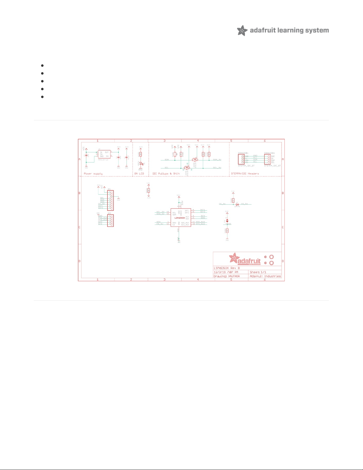
Schematic
The schematic is identical for the LSM6DSOX, ISM330DHCX, and LSM6DSO32
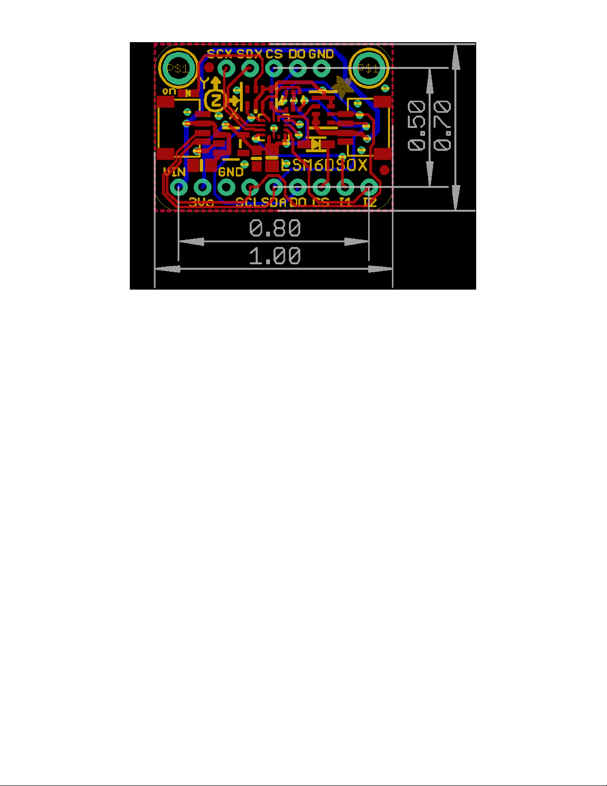
Fab Print
The fabrication print is identical for the LSM6DSOX and ISM330DHCX
© Adafruit Industries https://learn.adafruit.com/lsm6dsox-and-ism330dhc-6-dof-imu Page 19 of 21
Page 19
© Adafruit Industries https://learn.adafruit.com/lsm6dsox-and-ism330dhc-6-dof-imu Page 20 of 21
Page 20

© Adafruit Industries Last Updated: 2020-09-22 01:12:00 PM EDT Page 21 of 21
 Loading...