

Page 1
Adafruit LED Backpacks
Created by Melissa LeBlanc-Williams
https://learn.adafruit.com/adafruit-led-backpack
Last updated on 2022-10-03 01:18:04 PM EDT
©Adafruit Industries Page 1 of 161
Page 2

Table of Contents
Overview
1.2" 8x8 Matrix
Assembly
Arduino Setup
• Mini 8x8 Matrix Software
CircuitPython Wiring and Setup
• Wiring
• Library Setup
• Bundle Install
Python Wiring and Setup
• Wiring
• Setup
• Python Installation of HT16K33 Library
• Pillow Library
CircuitPython and Python Usage
• Initialization
• Setting the Brightness
• Setting the Blink Rate
• Setting Individual Pixels
• Filling the Entire Matrix
• Shifting the Matrix
• Displaying an Image (Pillow Only)
9
11
11
15
18
20
22
0.8" 8x8 Matrix
Assembly
Arduino Wiring and Setup
CircuitPython Wiring and Setup
• Wiring
• Library Setup
• Bundle Install
Python Wiring and Setup
• Wiring
• Setup
• Python Installation of HT16K33 Library
• Pillow Library
CircuitPython and Python Usage
• Initialization
• Setting the Brightness
• Setting the Blink Rate
• Setting Individual Pixels
25
26
29
32
34
35
©Adafruit Industries Page 2 of 161
Page 3

• Filling the Entire Matrix
• Shifting the Matrix
• Displaying an Image (Pillow Only)
1.2" 16x8 Matrix
Arduino Setup
• 16x8 Matrix Software
CircuitPython Wiring and Setup
• Wiring
• Library Setup
• Bundle Install
Python Wiring and Setup
• Wiring
• Setup
• Python Installation of HT16K33 Library
• Pillow Library
CircuitPython and Python Usage
• Initialization
• Setting the Brightness
• Setting the Blink Rate
• Setting Individual Pixels
• Filling the Entire Matrix
• Shifting the Matrix
• Displaying an Image (Pillow Only)
39
40
43
45
47
0.54" Alphanumeric Backpack
Pinouts
• STEMMA QT Revision-Only Features
• STEMMA QT Connectors
• On LED and LED Jumper
• Original and STEMMA QT Version Features
• Header Pin Through-Hole Pads
• Display Pin Through-Hole Pads
• HT16K33 Matrix Driver
• Address Jumper Pins
Assembly
• Attaching the Backpack
• Attaching Header
• Prepare the header strip:
• Add the Backpack:
Arduino Wiring and Setup
• Downloading the Arduino Library
• Wiring STEMMA QT Version
• Wiring Original Version
• Load Demo
• Library Reference
• ASCII data
• Writing Data
50
52
59
64
©Adafruit Industries Page 3 of 161
Page 4

CircuitPython Wiring and Setup
• Wiring STEMMA QT Version
• Wiring Original Version
• HT16K33 Library Installation
70
Python Wiring and Setup
• Wiring
• Wiring STEMMA QT Version
• Wiring Original Version
• Setup
• Python Installation of HT16K33 Library
• Pillow Library
CircuitPython and Python Usage
• Initialization
• Setting the Brightness
• Setting the Blink Rate
• Printing Text
• Printing Numbers
• Printing Hexidecimal Values
• Setting Individual Characters
• Setting Individual Segments
• Filling all Segments
• Scrolling Display Manually
• Displaying an Automatic Scrolling Marquee
• Full Example
0.56" 7-Segment Backpack
73
75
81
Assembly and Arduino Wiring
Arduino Setup
• Seven-Segment Backpack Firmware
CircuitPython Wiring and Setup
• Wiring
• Library Setup
• Bundle Install
Python Wiring and Setup
• Wiring
• Setup
• Python Installation of HT16K33 Library
• Pillow Library
CircuitPython and Python Usage
• Initialization
• Setting the Brightness
• Setting the Blink Rate
• Printing Text
• Printing Numbers
• Printing Hexidecimal Values
• Setting Individual Characters
• Setting Individual Segments
• Filling all Segments
82
85
88
91
93
©Adafruit Industries Page 4 of 161
Page 5

• Scrolling Display Manually
• Displaying the Colon
• Displaying an Automatic Scrolling Marquee
1.2" 7-segment Backpack
Assembly
Arduino Wiring and Setup
• Arduino Wiring - R3 and later
• Arduino Due and Other 3.3v Processors
• Arduino "Classic" Wiring
• Seven-Segment Backpack Firmware
CircuitPython Wiring and Setup
• Wiring
• Library Setup
• Bundle Install
Python Wiring and Setup
• Wiring
• Setup
• Python Installation of HT16K33 Library
• Pillow Library
CircuitPython and Python Usage
• Initialization
• Setting the Brightness
• Setting the Blink Rate
• Printing Text
• Printing Numbers
• Printing Hexidecimal Values
• Setting Individual Characters
• Setting Individual Segments
• Filling all Segments
• Scrolling Display Manually
• Displaying the Colon
• Setting the Left-Side Dots
• Setting the AM/PM Indicator
• Displaying an Automatic Scrolling Marquee
98
99
103
107
110
112
Bi-Color 8x8 Matrix
Assembly
Arduino Setup
CircuitPython Wiring and Setup
• Wiring
• Library Setup
• Bundle Install
Python Wiring and Setup
• Wiring
• Setup
©Adafruit Industries Page 5 of 161
117
118
121
124
126
Page 6

• Python Installation of HT16K33 Library
• Pillow Library
CircuitPython and Python Usage
• Initialization
• Setting the Brightness
• Setting the Blink Rate
• Setting Individual Pixels
• Filling the Entire Matrix
• Shifting the Matrix
• Displaying an Image (Pillow Only)
Bi-Color 24 Bargraph
Assembly
• Soldering on breadboard pins
Arduino Wiring and Setup
CircuitPython Wiring and Setup
• Wiring
• Library Setup
• Bundle Install
Python Wiring and Setup
• Wiring
• Setup
• Python Installation of HT16K33 Library
128
131
132
138
141
143
CircuitPython and Python Usage
• Initialization
• Setting the Brightness
• Setting the Blink Rate
• Setting Individual Bars
• Filling the Entire Bargraph
Connecting Multiple Backpacks
• Wire it Up
• Configure the Address
Changing I2C Address
• Changing Addresses
• Changing the address in your code
F.A.Q.
Downloads
• Software
• Files
• HT16K33 8x16 LED Backpack Breakout
• 8x8 0.8" LED Backpack
• 8x8 1.2" LED Backpack
• 8x8 1.2" Bi-Color LED Backpack
• 16x8 1.2" LED Backpacks
• 0.56" 7-Segment LED Backpack STEMMA QT
145
146
148
151
152
©Adafruit Industries Page 6 of 161
Page 7

• Quad 0.56" 7-Segment Original
• Quad 0.54" 14-segment Alphanumeric STEMMA QT Version
• Quad 0.54" 14-segment Alphanumeric Original Version
• Quad 1.2" 7-Segment
• Bicolor 24-Bargraph
©Adafruit Industries Page 7 of 161
Page 8

©Adafruit Industries Page 8 of 161
Page 9
Overview
What's better than a single LED? Lots of LEDs! A fun way to make a small display is to
use an 8x8 matrix(https://adafru.it/aLG) or a 4-digit 7-segment display(https://
adafru.it/aLH). Matrices like these are 'multiplexed' - so to control 64 LEDs you need
16 pins. That's a lot of pins, and there are driver chips like the MAX7219(http://
adafru.it/453) that can control a matrix for you but there's a lot of wiring to set up and
they take up a ton of space. Here at Adafruit we feel your pain! After all, wouldn't it be
awesome if you could control a matrix without tons of wiring? That's where these
adorable LED matrix backpacks come in.
We have them in quite a few flavors!
Adorable Mini 8x8(https://adafru.it/ttf)
•
Classic 1.2" 8x8 (round and square dots)(https://adafru.it/ttA)
•
Mini 1.2" 16x8 (round and square dots)(https://adafru.it/JpF)
•
4-digit 0.56" 7-segment(https://adafru.it/ttB)
•
4-digit 1.2" 7-segment(https://adafru.it/ttC)
•
4-digit 0.54" 14-segment Alphanumeric(https://adafru.it/ttD)
•
Bi-color 8x8(http://adafru.it/902)
•
Bi-color Bargraph(http://adafru.it/1721)
•
©Adafruit Industries Page 9 of 161
Page 10

The matrices use a driver chip that does all the heavy lifting for you: They have a built
in clock so they multiplex the display. They use constant-current drivers for ultra-
bright, consistent color (the images above are photographed at the dimmest setting
to avoid overloading our camera!), 1/16 step display dimming, all via a simple I2C
interface. The backpacks come with address-selection jumpers so you can connect
up to four mini 8x8's or eight 7-segments (or a combination, such as four mini 8x8's
and four 7-segments, etc) on a single I2C bus.
The product kit comes with a fully tested and assembled LED backpack, a 4-pin
header and the matrix of your choice. A bit of soldering is required to attach the
matrix onto the backpack but it's very easy to do and only takes about 5 minutes.
©Adafruit Industries Page 10 of 161
Page 11

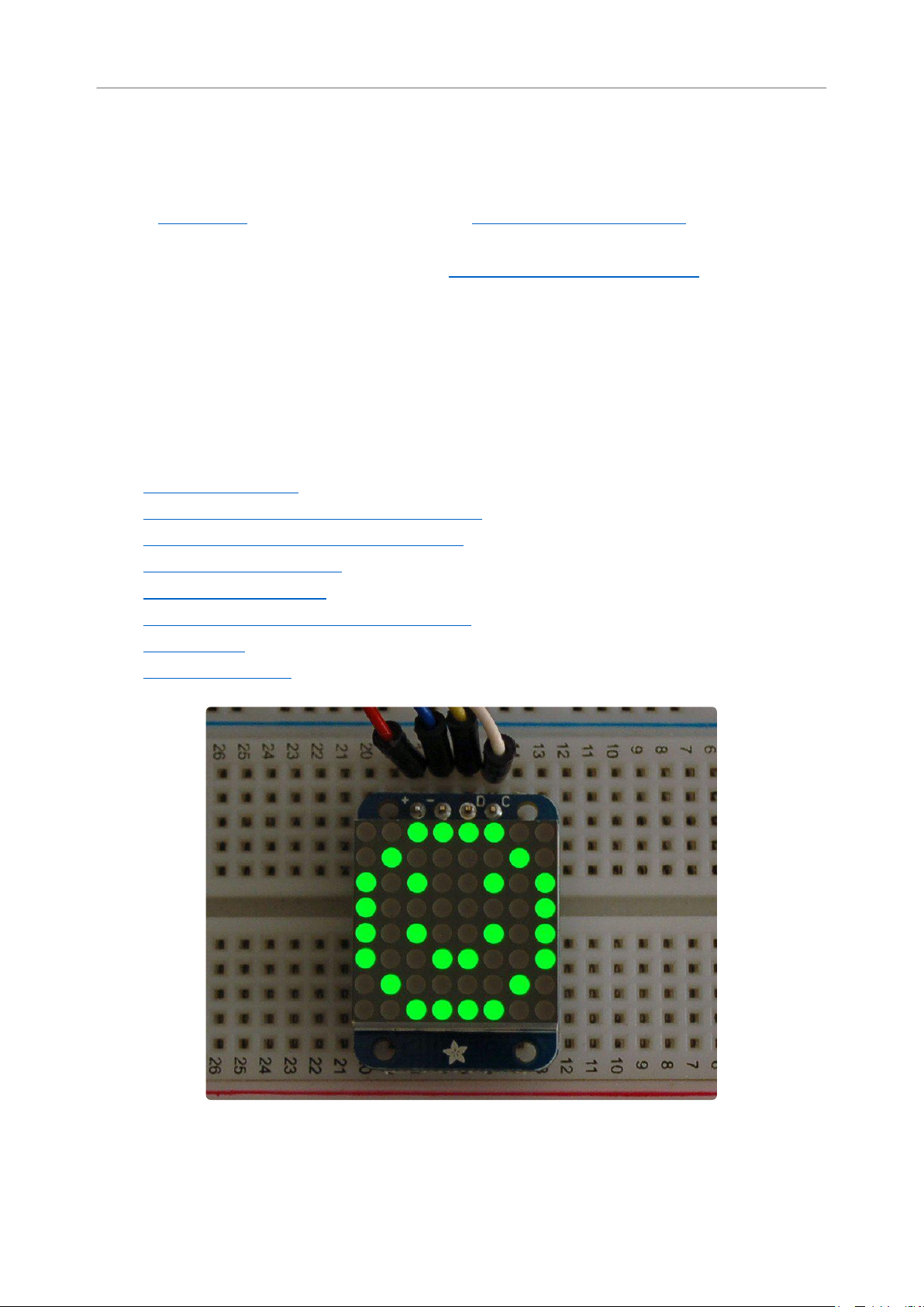
Of course, in classic Adafruit fashion, we also have a detailed tutorial showing you
how to solder, wire and control the display. We even wrote a very nice library for the
backpacks so you can get running in under half an hour, displaying images on the
matrix or numbers on the 7-segment. If you've been eyeing matrix displays but
hesitated because of the complexity, his is the solution you've been looking for!
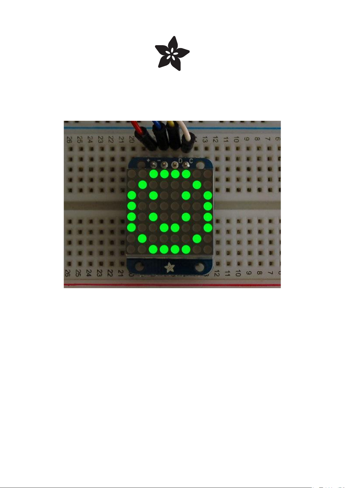
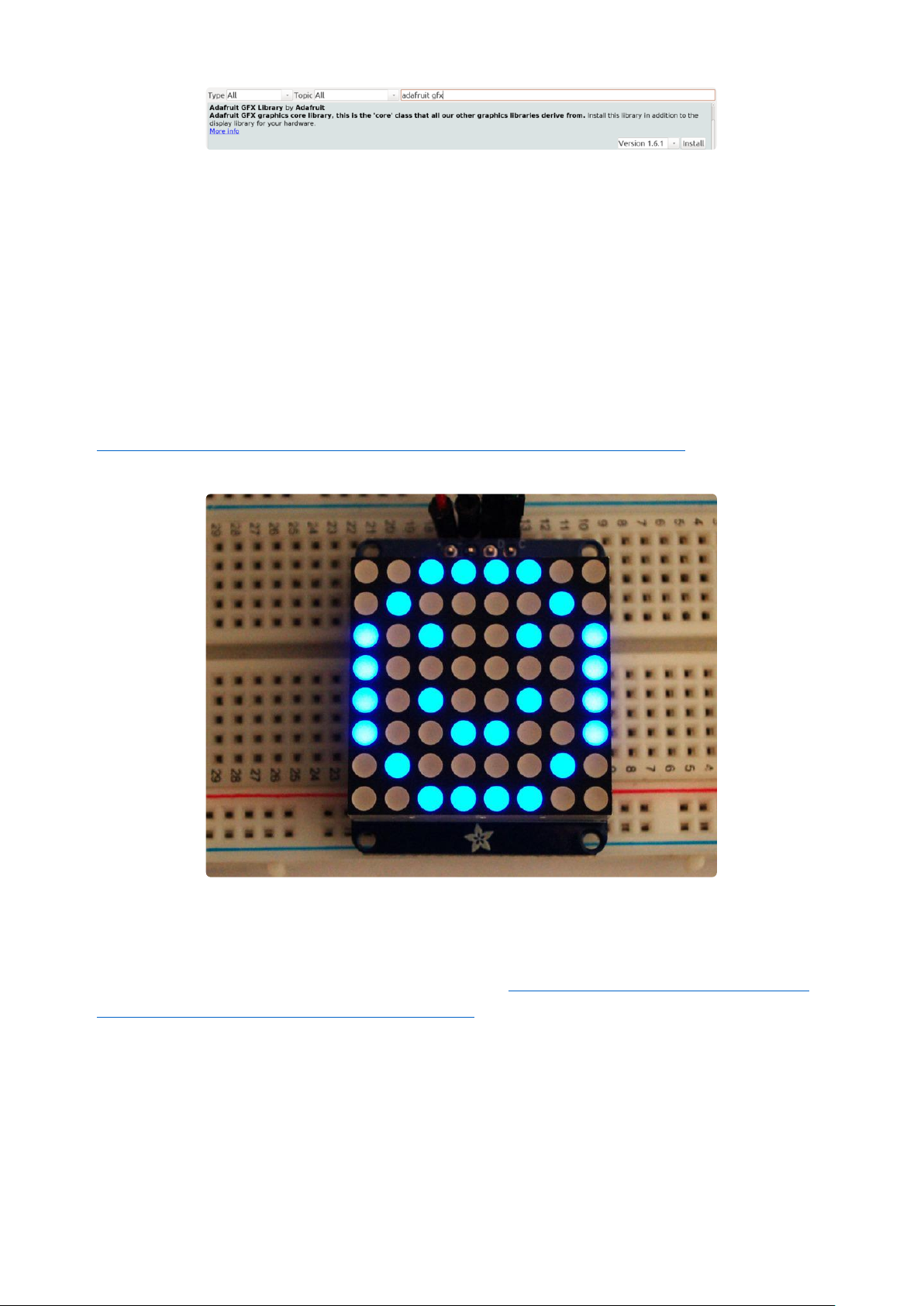
1.2" 8x8 Matrix
This version of the LED backpack is designed for the 1.2" 8x8 matrices. They measure
only 1.2"x1.2" so its a shame to use a massive array of chips to control it. This
backpack solves the annoyance of using 16 pins or a bunch of chips by having an I2C
constant-current matrix controller sit neatly on the back of the PCB. The controller
chip takes care of everything, drawing all 64 LEDs in the background. All you have to
do is write data to it using the 2-pin I2C interface. There are two address select pins
so you can select one of 8 addresses to control up to 8 of these on a single 2-pin I2C
bus (as well as whatever other I2C chips or sensors you like). The driver chip can 'dim'
the entire display from 1/16 brightness up to full brightness in 1/16th steps. It cannot
dim individual LEDs, only the entire display at once.
Assembly
These instruction apply to the 1.2" Matrix only! If you have a Bi-Color or 0.8"
square matrix, follow the links on the left side of the page.
©Adafruit Industries Page 11 of 161
Page 12

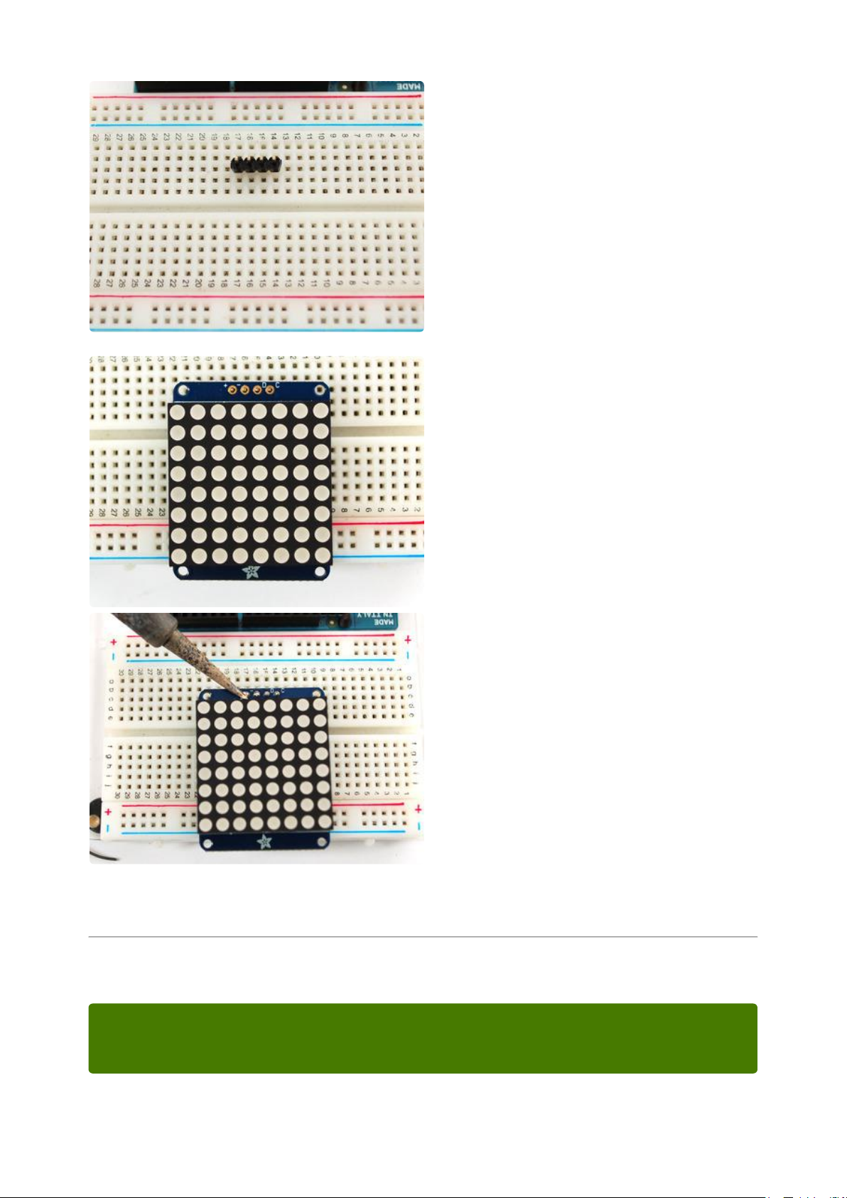
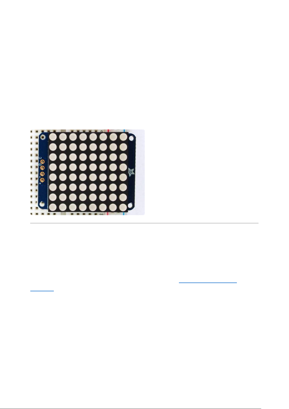
When you buy a pack from Adafruit, it
comes with the fully tested and assembled
backpack as well as a 8x8 matrix in one of
the colors we provide (say, red, yellow or
green). You'll need to solder the matrix
onto the backpack but its an easy task.
WATCH OUT! THE MATRIX MUST BE
INSTALLED THE RIGHT WAY!
First look for the line of text on the side of
the LED matrix
WATCH OUT! THE MATRIX MUST BE
INSTALLED THE RIGHT WAY!
Find the corner of the backpack with a
filled in dot. Make sure that the text on the
side of the matrix is on the same side as
the filled dot
©Adafruit Industries Page 12 of 161
Page 13

WATCH OUT! THE MATRIX MUST BE
INSTALLED THE RIGHT WAY!
Slide the matrix into the backpack and flip
it over. Triple check that the text is on the
same side as the From Adafruit text
©Adafruit Industries Page 13 of 161
Page 14

Solder in all 16 pins
Then clip the matrix leads short
©Adafruit Industries Page 14 of 161
Page 15
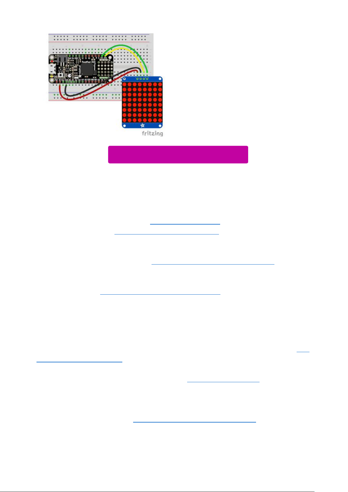
Now you're ready to wire it up to a
microcontroller. We'll assume you want to
use a 4pin header. You can also of course
solder wires directly. Place a 4-pin piece of
header with the LONG pins down into the
breadboard.
That's it! now you're ready to run the firmware!
Arduino Setup
Place the soldered backpack on top of the
header.
Solder the four pins
You can use these with a 3.3v or 5v microcontroller. Just connect the VCC+ pin is
the same voltage as the logic on your microcontroller.
©Adafruit Industries Page 15 of 161
Page 16
Mini 8x8 Matrix Software
We wrote a basic library to help you work with the mini 8x8 matrix backpack. The
library is written for the Arduino and will work with any Arduino as it just uses the I2C
pins. The code is very portable and can be easily adapted to any I2C-capable micro.
Wiring to the matrix is really easy
ConnectCLK to the I2C clock - on Arduino UNO thats Analog #5 (or SCL), on the
•
Leonardo its Digital #3, on the Mega its digital #21
ConnectDAT to the I2C data - on Arduino UNO thats Analog #4 (or SDA), on the
•
Leonardo its Digital #2, on the Mega its digital #20
ConnectGNDto common ground
•
ConnectVCC+to power - 5V is best but 3V also seems to work for 3V
•
microcontrollers.
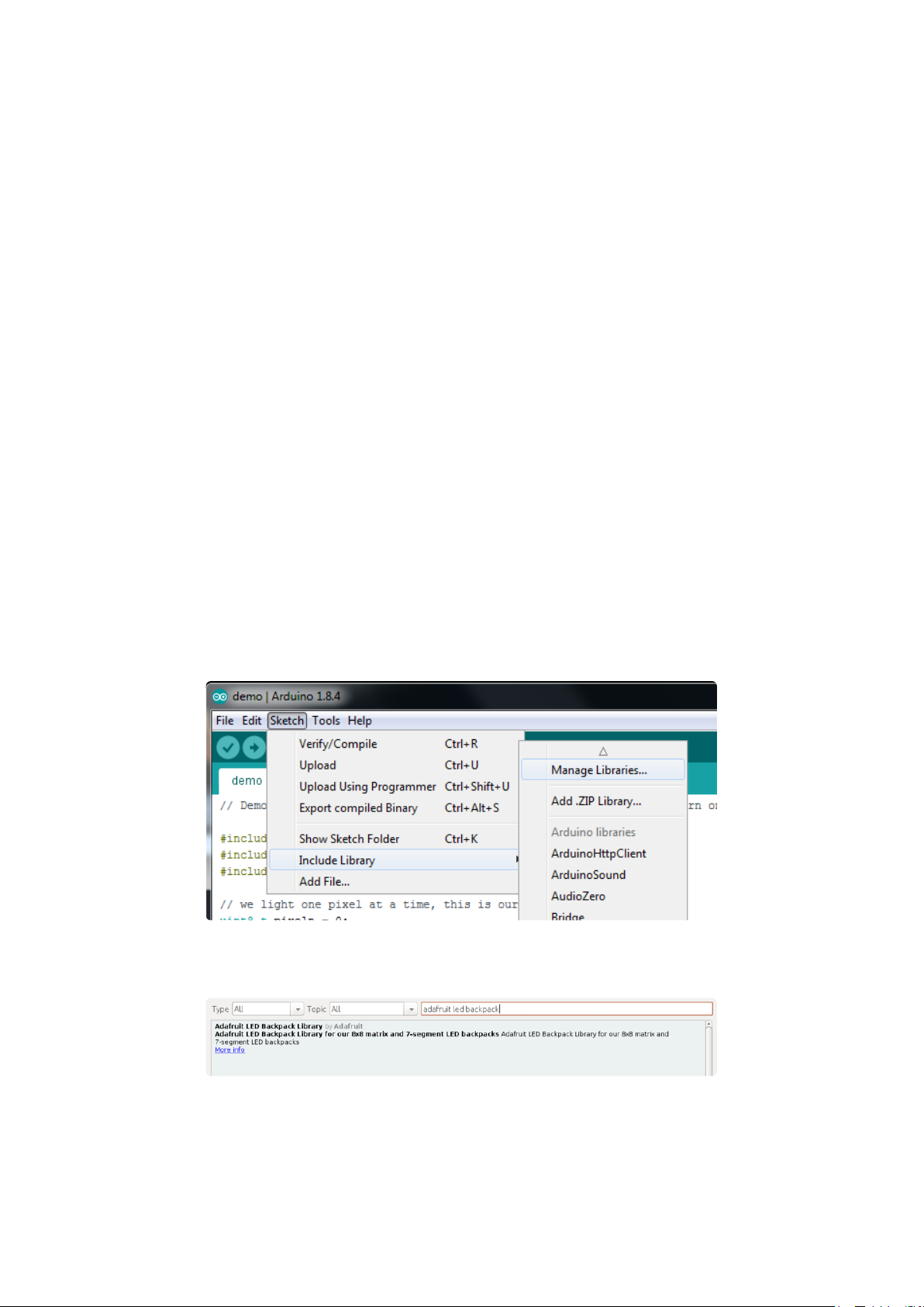
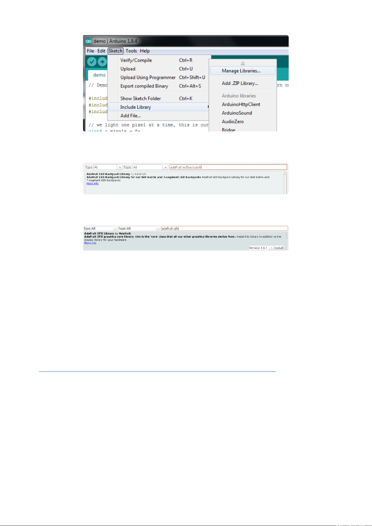
Next, download theAdafruit LED Backpacklibrary and theAdafruit GFXlibrary from
the Arduino library manager.
Open up the Arduino library manager:
Search for theAdafruit LED Backpacklibrary and install it
Search for theAdafruit GFXlibrary and install it
©Adafruit Industries Page 16 of 161
Page 17
If using an earlier version of the Arduino IDE (prior to 1.8.10), also locate and install Ad
afruit_BusIO (newer versions will install this dependency automatically).
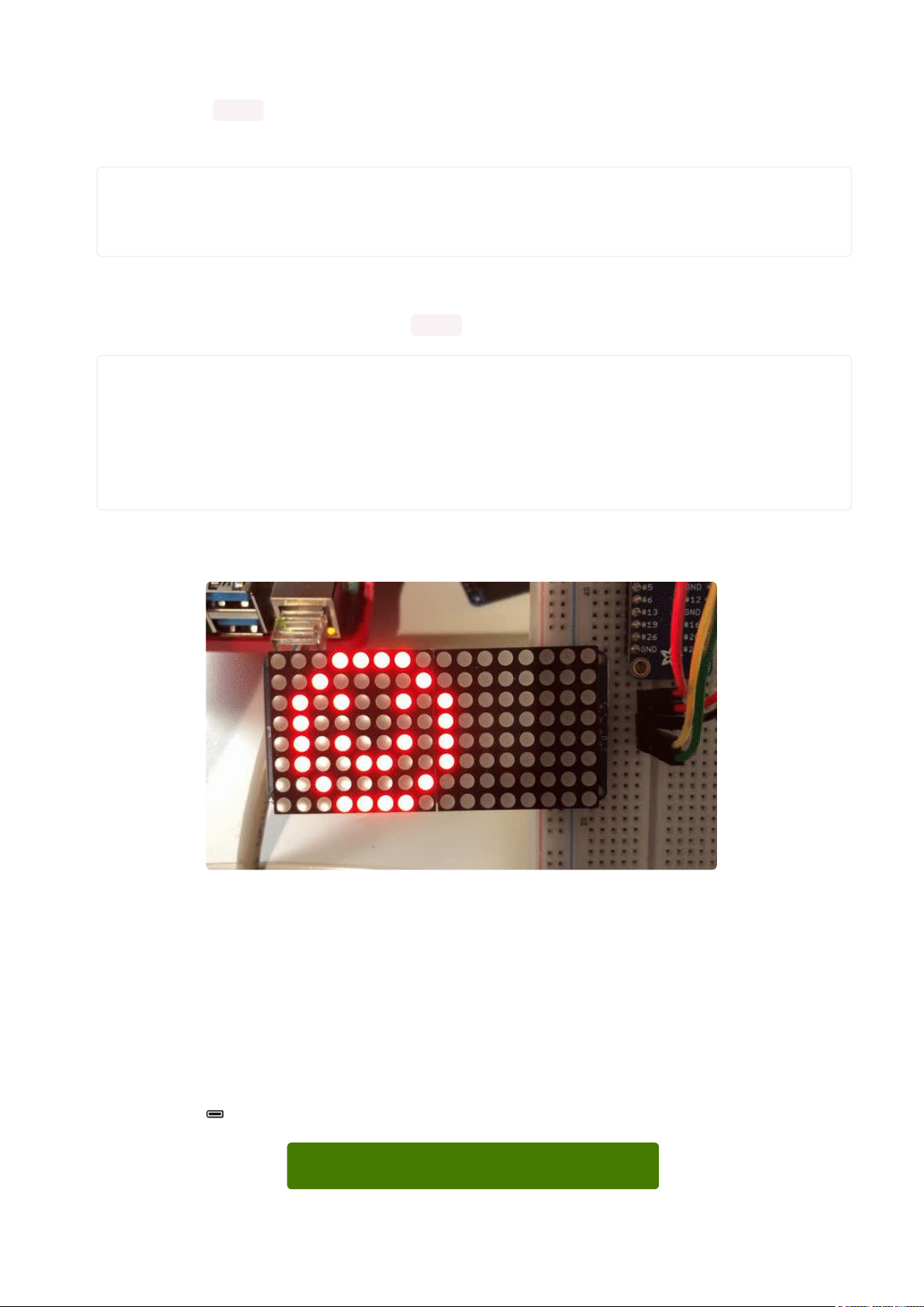
You should now be able to select the
File→Examples→Adafruit_LEDBackpack→matrix88 example sketch. Upload it to your
Arduino as usual. You should see a basic test program that goes through a bunch of
different drawing routine
We also have a great tutorial on Arduino library installation at:
http://learn.adafruit.com/adafruit-all-about-arduino-libraries-install-use(https://
adafru.it/aYM)
Once you're happy that the matrix works, you can write your own sketches. The 8x8
matrix supports everything the Adafruit GFX library - drawing pixels, lines, rectancles,
circles, triangles, roundrects, and small bitmaps. For more details check out the GFX
page which will detail all of the GFX routines(https://adafru.it/aPx).
All the drawing routines only change the display memory kept by the Arduino. Don't
forget to call writeDisplay() after drawing to 'save' the memory out to the matrix via
I2C.
©Adafruit Industries Page 17 of 161
Page 18
There are also a few small routines that are special to the matrix:
setBrightness(brighness)- will let you change the overall brightness of the entire
•
display. 0 is least bright, 15 is brightest and is what is initialized by the display
when you start. You can call this function at any time to change the brightness of
the -entire- display
blinkRate(rate) - You can blink the entire display. 0 is no blinking. 1, 2 or 3 is for
•
display blinking.You can call this function at any time to change the blink rate of
the -entire- display
The default orientation for graphics
commands on this display places pixel
(0,0) at the top-left when the header is at
the left and Adafruit logo at the right. To
use the matrix as shown above (header at
top, logo at bottom), call
matrix.setRotation(3) before issuing
graphics commands.
CircuitPython Wiring and Setup
Wiring
It's easy to use LED Matrices with CircuitPython and the Adafruit CircuitPython
HT16K33(https://adafru.it/u1E) library. This module allows you to easily write
CircuitPython code to control the display.
You can use this sensor with any CircuitPython microcontroller board.
We'll cover how to wire the LED Matrix to your CircuitPython microcontroller board.
First assemble your LED Matrix.
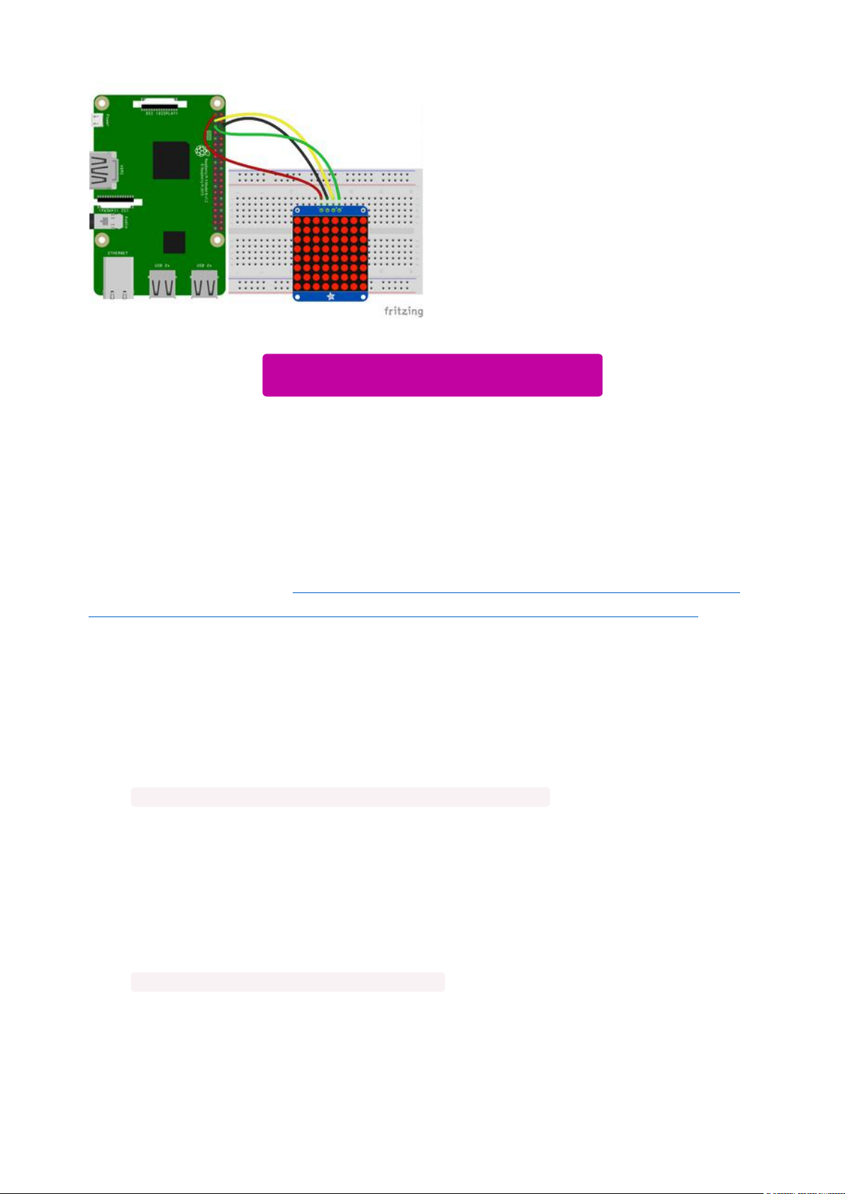
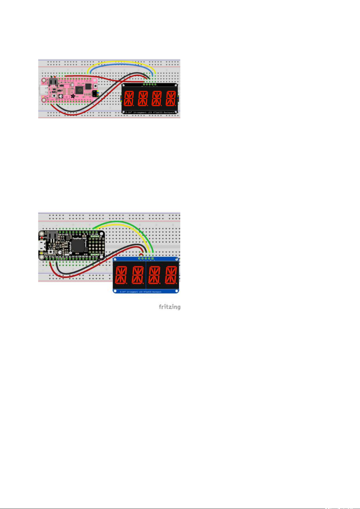
Connect the LED Matrix to your microcontroller board as shown below.
©Adafruit Industries Page 18 of 161
Page 19
Microcontroller 3Vto LED Matrix VIN
Microcontroller GNDto LED MatrixGND
Microcontroller SCLto LED MatrixSCL
Microcontroller SDAto LED MatrixSDA
Download Fritzing Object
https://adafru.it/Ify
Library Setup
To use the LED backpackwith yourAdafruit CircuitPython(https://adafru.it/BlM)board
you'll need to install theAdafruit_CircuitPython_HT16K33(https://adafru.it/u1E) library
on your board.
First make sure you are running thelatest version of Adafruit CircuitPython(https://
adafru.it/tBa)for your board. Next you'll need to install the necessary librariesto use
the hardware--read below and carefully follow the referenced steps to find and install
these libraries from Adafruit's CircuitPython library bundle(https://adafru.it/zdx).
Bundle Install
For express boards that have extra flash storage, like the Feather/Metro M0 express
and Circuit Playground express, you can easily install the necessary libraries with Ada
fruit's CircuitPython bundle(https://adafru.it/zdx). This is an all-in-one package that
includes the necessary libraries to use the LED backpack display with CircuitPython.
For details on installing the bundle, read about CircuitPython Libraries(https://
adafru.it/ABU).
Remember for non-express boards like the Trinket M0, Gemma M0, and Feather/
Metro M0 basic you'll need to manually install the necessary libraries(https://adafru.it/
ABU) from the bundle:
adafruit_ht16k33•
©Adafruit Industries Page 19 of 161
Page 20
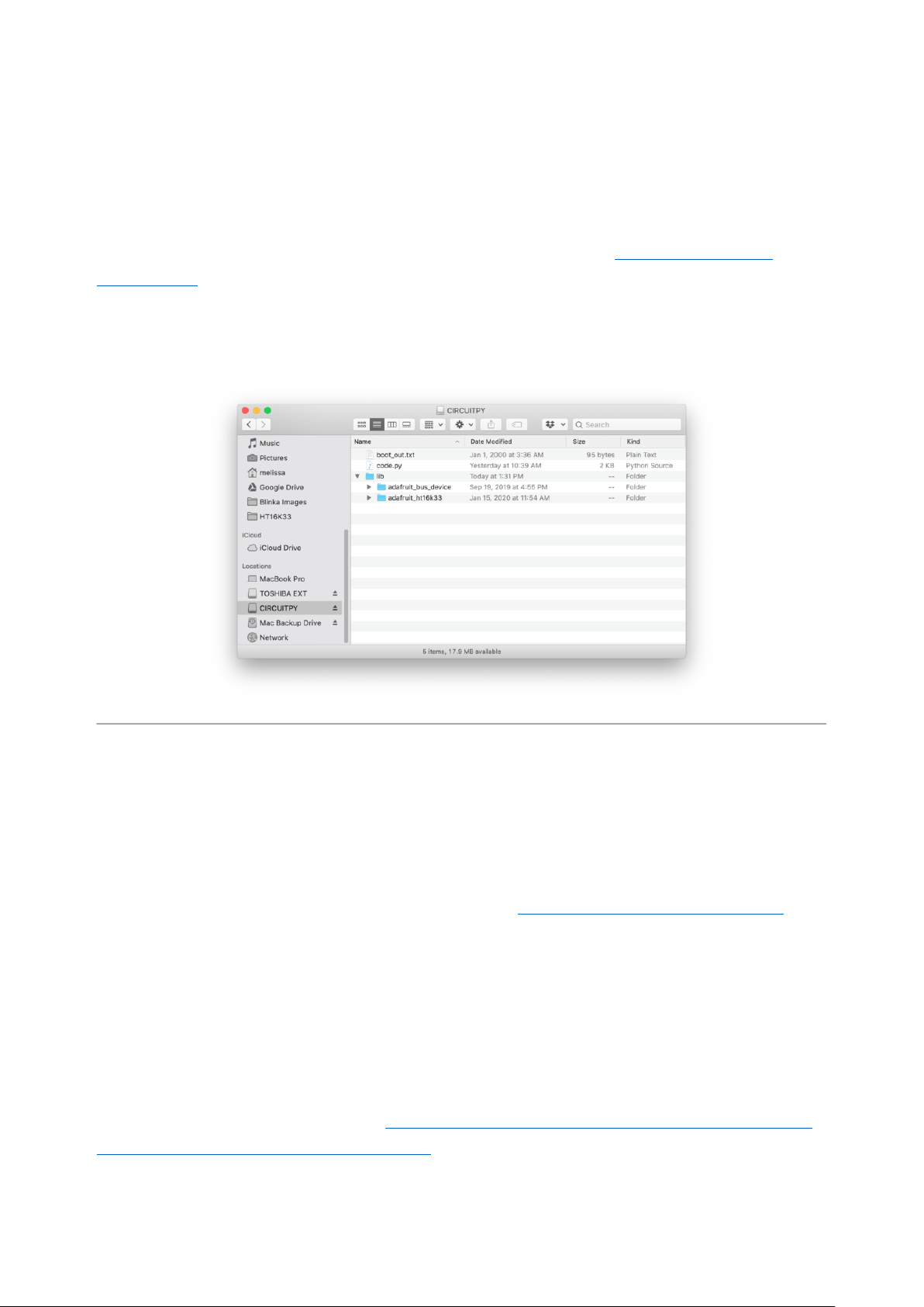
adafruit_bus_device
•
If your board supports USB mass storage, like the M0-based boards, then simply drag
the files to the board's file system.Note on boards without external SPI flash, like a
Feather M0 or Trinket/Gemma M0, you might run into issues on Mac OSX with hidden
files taking up too much space when drag and drop copying,see this page for a
workaround(https://adafru.it/u1d).
Before continuing make sure your board's lib folder or root filesystem has at least
theadafruit_ht16k33 andadafruit_bus_devicefolders/modules copied over.
Python Wiring and Setup
Wiring
It's easy to use LED Matrices with Python and the Adafruit CircuitPython HT16K33(htt
ps://adafru.it/u1E) library. This library allows you to easily write Python code to control
the display.
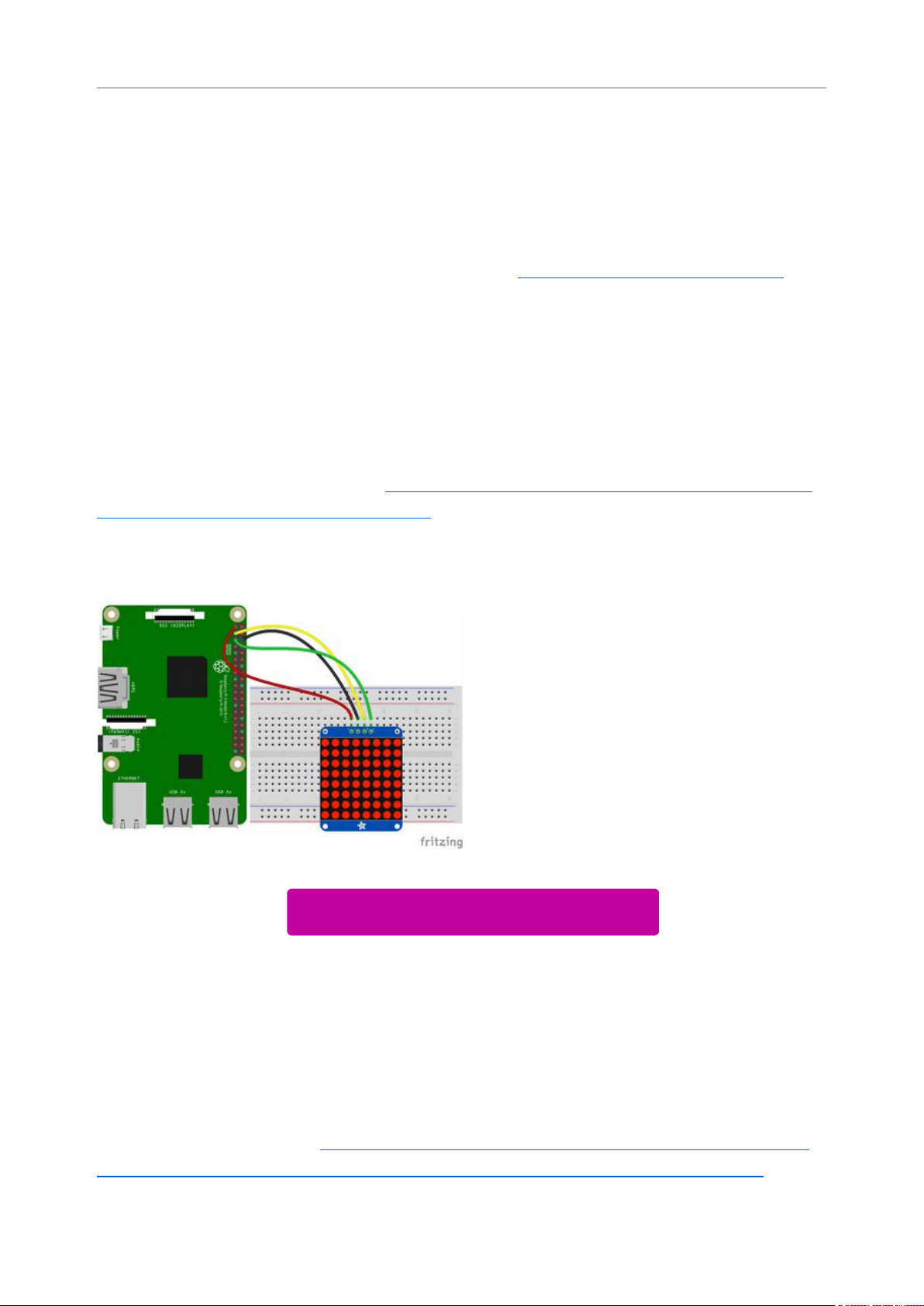
We'll cover how to wire the LED Matrix to your Raspberry Pi. First assemble your LED
Matrix.
Since there's dozens of Linux computers/boards you can use we will show wiring for
Raspberry Pi. For other platforms, please visit the guide for CircuitPython on Linux to
see whether your platform is supported(https://adafru.it/BSN).
Connect the LED Matrix as shown below to your Raspberry Pi.
©Adafruit Industries Page 20 of 161
Page 21
Raspberry Pi 3.3VtoLED Matrix VIN
Raspberry Pi GNDto LED MatrixGND
Raspberry Pi SCLto LED MatrixSCL
Raspberry Pi SDAto LED MatrixSDA
Download Fritzing Object
https://adafru.it/Ifz
Setup
You'll need to install the Adafruit_Blinka library that provides the CircuitPython
support in Python. This may also require enabling I2C on your platform and verifying
you are running Python 3. Since each platform is a little different, and Linux changes
often, please visit the CircuitPython on Linux guide to get your computer ready(https:
//adafru.it/BSN)!
Python Installation of HT16K33 Library
Once that's done, from your command line run the following command:
pip3 install adafruit-circuitpython-ht16k33
•
If your default Python is version 3 you may need to run 'pip' instead. Just make sure
you aren't trying to use CircuitPython on Python 2.x, it isn't supported!
If that complains about pip3 not being installed, then run this first to install it:
sudo apt-get install python3-pip
•
©Adafruit Industries Page 21 of 161
Page 22

Pillow Library
We also need PIL, the Python Imaging Library, to allow using text with custom fonts.
There are several system libraries that PIL relies on, so installing via a package
manager is the easiest way to bring in everything:
sudo apt-get install python3-pil
•
That's it. You should be ready to go.
CircuitPython and Python Usage
The following section will show how to control the LED backpackfrom the board's
Python prompt / REPL. You'll walk through how to control the LED display and learn
how to use the CircuitPython module built for the display.
Firstconnect to the board's serial REPL(https://adafru.it/Awz)so you are at the
CircuitPython>>>prompt.
Initialization
First you'll need to initialize the I2C bus for your board. It's really easy, first import the
necessary modules. In this case, we'll use board and Matrix8x8 .
Then just use board.I2C() to create the I2C instance using the default SCL and
SDA pins (which will be marked on the boards pins if using a Feather or similar
Adafruit board).
Then to initialize the matrix, you just pass i2c in.
import board
from adafruit_ht16k33.matrix import Matrix8x8
i2c = board.I2C()
matrix = Matrix8x8(i2c)
If you bridged the address pads on the back of the display, you could pass in the
address. The addresses for the HT16K33 can range between 0x70 and 0x77
depending on which pads you have bridged, with 0x70 being used if you haven't
©Adafruit Industries Page 22 of 161
Page 23

bridged any of them. For instance, if you bridge only the A0 pad, you would use
0x71 like this:
matrix = Matrix8x8(i2c, address=0x71)
Setting the Brightness
You can set the brightness of the display, but changing it will set the brightness of the
entire display and not individual segments. If can be adjusted in 1/16 increments betw
een 0 and 1.0 with 1.0 being the brightest. So to set the display to half brightness, you
would use the following:
matrix.brightness = 0.5
Setting the Blink Rate
You can set the blink rate of the display, but changing it will set the brightness of the
entire display and not individual pixels. If can be adjusted in 1/4 incrementsbetween 0
and 3with 3 being the fastest blinking. So to set the display to blink at full speed, you
would use the following:
matrix.blink_rate = 3
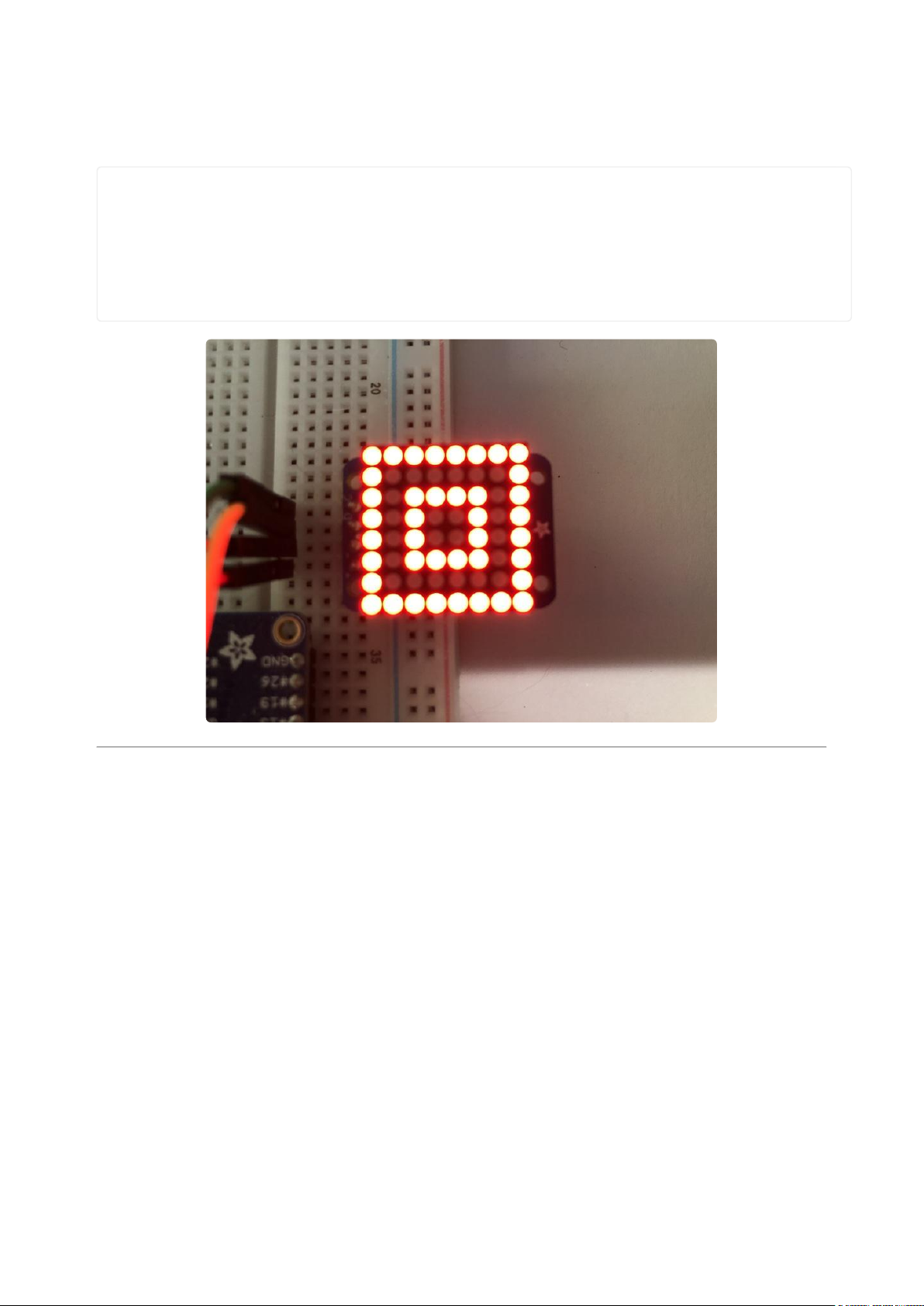
Setting Individual Pixels
To set individual pixels to on, you simply treat the matrix object as a
multidimensional list and set it to 1.
matrix[0, 0] = 1
matrix[4, 4] = 1
matrix[7, 7] = 1
Filling the Entire Matrix
To fill the entire matrix, just use the fill() function and pass in either 0 or 1 depending
on whether you want all pixels off or on. For instance, if you wanted to set everything
to on, you would use:
matrix.fill(1)
©Adafruit Industries Page 23 of 161
Page 24

Shifting the Matrix
To shift the pixels on the matrix, there are 5 functions you can use. The main function,
called shift(), is used to shift the pixels, up, down, left, right, or even diagonally. By
passing a positive number, it will shift the pixels right/up and passing a negative
number will shift them left/down. For instance:
matrix.shift(2, 0) # shift pixels to the right by 2
matrix.shift(-1, 0) # shift pixels to the left by 1
matrix.shift(0, -3) # shift pixels down by 3
matrix.shift(-2, 2) # shift pixels left by 2 and up by 2
You can pass True as a third parameter to loop all the pixels that get shifted off over
to the other side.
matrix.shift(2, 0, True) # loop pixels to the right by 2
matrix.shift(-1, 0, True) # loop pixels to the left by 1
matrix.shift(0, -3, True) # loop pixels down by 3
matrix.shift(-2, 2, True) # loop pixels left by 2 and up by 2
Additionally, there are a few convenience functions that will shift the pixels by one.
These can also be passed a value of True to loop the pixels.
matrix.shift_up() # Shift pixels up
matrix.shift_left() # Shift pixels left
matrix.shift_down() # Shift pixels down
matrix.shift_right() # Shift pixels right
matrix.shift_up(True) # Loop pixels up
matrix.shift_left(True) # Loop pixels left
matrix.shift_down(True) # Loop pixels down
matrix.shift_right(True) # Loop pixels right
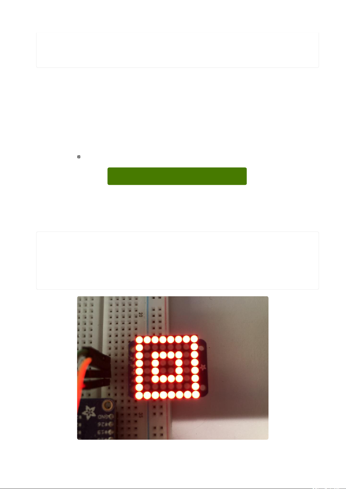
Displaying an Image (Pillow Only)
Additionally, when using with the Raspberry Pi, you can use the Pillow library to
display an image to the Matrix. The image will need to be the same exact size as the
Matrix. In this case, it should be 8x8 pixels. As an example, you can save the image
below asmyimage.png.
Download Image
https://adafru.it/ICR
©Adafruit Industries Page 24 of 161
Page 25
Then if you want to display the image calledmyimage.png, you would use something
like this:
import board
from PIL import Image
from adafruit_ht16k33 import matrix
matrix = matrix.Matrix8x8(board.I2C())
image = Image.open("myimage.png")
matrix.image(image)
0.8" 8x8 Matrix
This version of the LED backpack is designed for these very cute miniature 8x8
matrices. They measure only 0.8"x0.8" so its a shame to use a massive array of chips
to control it. This backpack solves the annoyance of using 16 pins or a bunch of chips
by having an I2C constant-current matrix controller sit neatly on the back of the PCB.
The controller chip takes care of everything, drawing all 64 LEDs in the background.
All you have to do is write data to it using the 2-pin I2C interface. There are two
address select pins so you can select one of 4 addresses to control up to 4 of these
on a single 2-pin I2C bus (as well as whatever other I2C chips or sensors you like).
The driver chip can 'dim' the entire display from 1/16 brightness up to full brightness in
1/16th steps. It cannot dim individual LEDs, only the entire display at once.
©Adafruit Industries Page 25 of 161
Page 26

Assembly
These instruction apply to the 0.8" Matrix only! If you have a Bi-Color or 1.2"
square matrix, follow the links on the left side of the page.
When you buy a pack from Adafruit, it
comes with the fully tested and assembled
backpack as well as a 8x8 matrix in one of
the colors we provide (say, red, yellow or
green). You'll need to solder the matrix
onto the backpack but its an easy task.
©Adafruit Industries Page 26 of 161
Page 27

Remove the parts from packaging and
place the LED matrix OVER the silkscreen
side. It can go 'either way' - the matrix is
symmetric so as long as it goes onto the
front it will work in any orientation. Do not
solder the matrix over the chip on the back
of the backpack - it will not work then!
Turn the backpack over so its sitting flat on
the matrix.
Solder all 16 pins.
©Adafruit Industries Page 27 of 161
Page 28

Clip the long pins.
Now you're ready to wire it up to a
microcontroller. We'll assume you want to
use a 4pin header. You can also of course
solder wires directly. Place a 4-pin piece of
header with the LONG pins down into the
breadboard.
©Adafruit Industries Page 28 of 161
Page 29

Place the soldered backpack on top of the
header.
Solder 'em!
That's it! now you're ready to run the firmware!
Arduino Wiring and Setup
You can use these with a 3.3v or 5v microcontroller. Just connect the VCC+ pin is
the same voltage as the logic on your microcontroller.
We wrote a basic library to help you work with the mini 8x8 matrix backpack. The
library is written for the Arduino and will work with any Arduino as it just uses the I2C
pins. The code is very portable and can be easily adapted to any I2C-capable micro.
Wiring to the matrix is really easy
ConnectCLK to the I2C clock - on Arduino UNO thats Analog #5 (or SCL), on the
•
Leonardo its Digital #3, on the Mega its digital #21
ConnectDAT to the I2C data - on Arduino UNO thats Analog #4 (or SDA), on the
•
Leonardo its Digital #2, on the Mega its digital #20
ConnectGNDto common ground
•
©Adafruit Industries Page 29 of 161
Page 30

ConnectVCC+to power - 5V is best but 3V also seems to work for 3V
•
microcontrollers.
Next, download theAdafruit LED Backpacklibrary and theAdafruit GFXlibrary from
the Arduino library manager.
Open up the Arduino library manager:
Search for theAdafruit LED Backpack library and install it
Search for theAdafruit GFXlibrary and install it
If using an earlier version of the Arduino IDE (prior to 1.8.10), also locate and install Ad
afruit_BusIO (newer versions will install this dependency automatically).
Once you've restarted you should be able to select the
File→Examples→Adafruit_LEDBackpack→matrix88 example sketch. Upload it to your
Arduino as usual. You should see a basic test program that goes through a bunch of
different drawing routines
©Adafruit Industries Page 30 of 161
Page 31

We also have a great tutorial on Arduino library installation at:
http://learn.adafruit.com/adafruit-all-about-arduino-libraries-install-use(https://
adafru.it/aYM)
Once you're happy that the matrix works, you can write your own sketches. The 8x8
matrix supports everything the Adafruit GFX library - drawing pixels, lines, rectancles,
circles, triangles, roundrects, and small bitmaps. For more details check out the GFX
page which will detail all of the GFX routines(https://adafru.it/aPx).
All the drawing routines only change the display memory kept by the Arduino. Don't
forget to call writeDisplay() after drawing to 'save' the memory out to the matrix via
I2C.
There are also a few small routines that are special to the matrix:
setBrightness(brighness)- will let you change the overall brightness of the entire
•
display. 0 is least bright, 15 is brightest and is what is initialized by the display
when you start
blinkRate(rate) - You can blink the entire display. 0 is no blinking. 1, 2 or 3 is for
•
display blinking.
©Adafruit Industries Page 31 of 161
Page 32
CircuitPython Wiring and Setup
Wiring
It's easy to use LED Matrices with CircuitPython and the Adafruit CircuitPython
HT16K33(https://adafru.it/u1E) library. This module allows you to easily write
CircuitPython code to control the display.
You can use this sensor with any CircuitPython microcontroller board.
We'll cover how to wire the LED Matrix to your CircuitPython microcontroller board.
First assemble your LED Matrix.
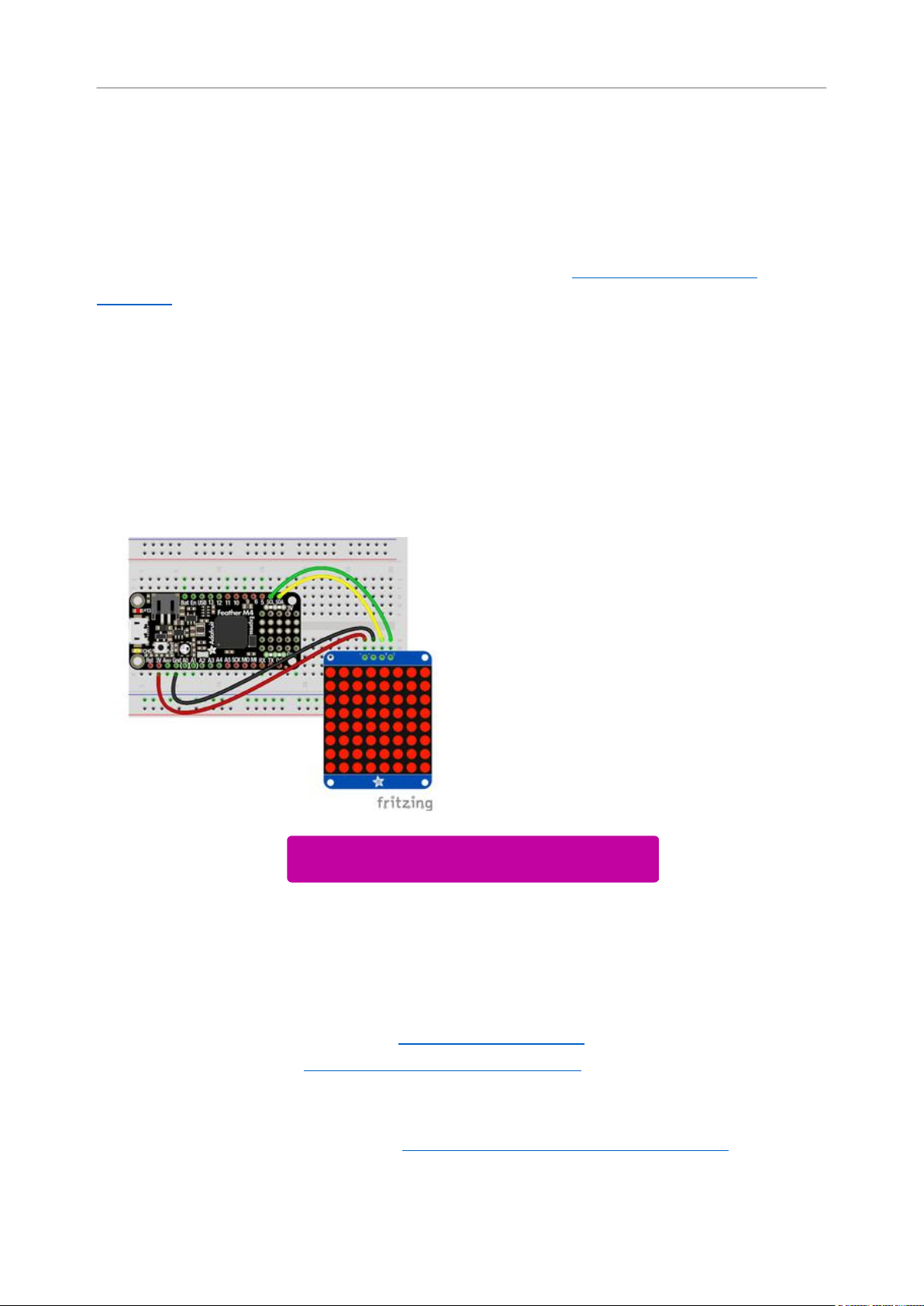
Connect the LED Matrix to your microcontroller board as shown below.
Microcontroller 3Vto LED Matrix VIN
Microcontroller GNDto LED MatrixGND
Microcontroller SCLto LED MatrixSCL
Microcontroller SDAto LED MatrixSDA
Download Fritzing Object
https://adafru.it/Ify
Library Setup
To use the LED backpackwith yourAdafruit CircuitPython(https://adafru.it/BlM)board
you'll need to install theAdafruit_CircuitPython_HT16K33(https://adafru.it/u1E) library
on your board.
First make sure you are running thelatest version of Adafruit CircuitPython(https://
adafru.it/tBa)for your board. Next you'll need to install the necessary librariesto use
©Adafruit Industries Page 32 of 161
Page 33
the hardware--read below and carefully follow the referenced steps to find and install
these libraries from Adafruit's CircuitPython library bundle(https://adafru.it/zdx).
Bundle Install
For express boards that have extra flash storage, like the Feather/Metro M0 express
and Circuit Playground express, you can easily install the necessary libraries with Ada
fruit's CircuitPython bundle(https://adafru.it/zdx). This is an all-in-one package that
includes the necessary libraries to use the LED backpack display with CircuitPython.
For details on installing the bundle, read about CircuitPython Libraries(https://
adafru.it/ABU).
Remember for non-express boards like the Trinket M0, Gemma M0, and Feather/
Metro M0 basic you'll need to manually install the necessary libraries(https://adafru.it/
ABU) from the bundle:
adafruit_ht16k33
•
adafruit_bus_device
•
If your board supports USB mass storage, like the M0-based boards, then simply drag
the files to the board's file system.Note on boards without external SPI flash, like a
Feather M0 or Trinket/Gemma M0, you might run into issues on Mac OSX with hidden
files taking up too much space when drag and drop copying,see this page for a
workaround(https://adafru.it/u1d).
Before continuing make sure your board's lib folder or root filesystem has at least
theadafruit_ht16k33 andadafruit_bus_devicefolders/modules copied over.
©Adafruit Industries Page 33 of 161
Page 34
Python Wiring and Setup
Wiring
It's easy to use LED Matrices with Python and the Adafruit CircuitPython HT16K33(htt
ps://adafru.it/u1E) library. This library allows you to easily write Python code to control
the display.
We'll cover how to wire the LED Matrix to your Raspberry Pi. First assemble your LED
Matrix.
Since there's dozens of Linux computers/boards you can use we will show wiring for
Raspberry Pi. For other platforms, please visit the guide for CircuitPython on Linux to
see whether your platform is supported(https://adafru.it/BSN).
Connect the LED Matrix as shown below to your Raspberry Pi.
Raspberry Pi 3.3VtoLED Matrix VIN
Raspberry Pi GNDto LED MatrixGND
Raspberry Pi SCLto LED MatrixSCL
Raspberry Pi SDAto LED MatrixSDA
Download Fritzing Object
https://adafru.it/Ifz
Setup
You'll need to install the Adafruit_Blinka library that provides the CircuitPython
support in Python. This may also require enabling I2C on your platform and verifying
you are running Python 3. Since each platform is a little different, and Linux changes
often, please visit the CircuitPython on Linux guide to get your computer ready(https:
//adafru.it/BSN)!
©Adafruit Industries Page 34 of 161
Page 35

Python Installation of HT16K33 Library
Once that's done, from your command line run the following command:
pip3 install adafruit-circuitpython-ht16k33
•
If your default Python is version 3 you may need to run 'pip' instead. Just make sure
you aren't trying to use CircuitPython on Python 2.x, it isn't supported!
If that complains about pip3 not being installed, then run this first to install it:
sudo apt-get install python3-pip
•
Pillow Library
We also need PIL, the Python Imaging Library, to allow using text with custom fonts.
There are several system libraries that PIL relies on, so installing via a package
manager is the easiest way to bring in everything:
sudo apt-get install python3-pil
•
That's it. You should be ready to go.
CircuitPython and Python Usage
The following section will show how to control the LED backpackfrom the board's
Python prompt / REPL. You'll walk through how to control the LED display and learn
how to use the CircuitPython module built for the display.
Firstconnect to the board's serial REPL(https://adafru.it/Awz)so you are at the
CircuitPython>>>prompt.
Initialization
First you'll need to initialize the I2C bus for your board. It's really easy, first import the
necessary modules. In this case, we'll use board and Matrix8x8 .
©Adafruit Industries Page 35 of 161
Page 36

Then just use board.I2C() to create the I2C instance using the default SCL and
SDA pins (which will be marked on the boards pins if using a Feather or similar
Adafruit board).
Then to initialize the matrix, you just pass i2c in.
import board
from adafruit_ht16k33.matrix import Matrix8x8
i2c = board.I2C()
matrix = Matrix8x8(i2c)
If you bridged the address pads on the back of the display, you could pass in the
address. The addresses for the HT16K33 can range between 0x70 and 0x77
depending on which pads you have bridged, with 0x70 being used if you haven't
bridged any of them. For instance, if you bridge only the A0 pad, you would use
0x71 like this:
matrix = Matrix8x8(i2c, address=0x71)
Setting the Brightness
You can set the brightness of the display, but changing it will set the brightness of the
entire display and not individual segments. If can be adjusted in 1/16 increments betw
een 0 and 1.0 with 1.0 being the brightest. So to set the display to half brightness, you
would use the following:
matrix.brightness = 0.5
Setting the Blink Rate
You can set the blink rate of the display, but changing it will set the brightness of the
entire display and not individual pixels. If can be adjusted in 1/4 incrementsbetween 0
and 3with 3 being the fastest blinking. So to set the display to blink at full speed, you
would use the following:
matrix.blink_rate = 3
©Adafruit Industries Page 36 of 161
Page 37

Setting Individual Pixels
To set individual pixels to on, you simply treat the matrix object as a
multidimensional list and set it to 1.
matrix[0, 0] = 1
matrix[4, 4] = 1
matrix[7, 7] = 1
Filling the Entire Matrix
To fill the entire matrix, just use the fill() function and pass in either 0 or 1 depending
on whether you want all pixels off or on. For instance, if you wanted to set everything
to on, you would use:
matrix.fill(1)
Shifting the Matrix
To shift the pixels on the matrix, there are 5 functions you can use. The main function,
called shift(), is used to shift the pixels, up, down, left, right, or even diagonally. By
passing a positive number, it will shift the pixels right/up and passing a negative
number will shift them left/down. For instance:
matrix.shift(2, 0) # shift pixels to the right by 2
matrix.shift(-1, 0) # shift pixels to the left by 1
matrix.shift(0, -3) # shift pixels down by 3
matrix.shift(-2, 2) # shift pixels left by 2 and up by 2
You can pass True as a third parameter to loop all the pixels that get shifted off over
to the other side.
matrix.shift(2, 0, True) # loop pixels to the right by 2
matrix.shift(-1, 0, True) # loop pixels to the left by 1
matrix.shift(0, -3, True) # loop pixels down by 3
matrix.shift(-2, 2, True) # loop pixels left by 2 and up by 2
Additionally, there are a few convenience functions that will shift the pixels by one.
These can also be passed a value of True to loop the pixels.
matrix.shift_up() # Shift pixels up
matrix.shift_left() # Shift pixels left
matrix.shift_down() # Shift pixels down
©Adafruit Industries Page 37 of 161
Page 38
matrix.shift_right() # Shift pixels right
matrix.shift_up(True) # Loop pixels up
matrix.shift_left(True) # Loop pixels left
matrix.shift_down(True) # Loop pixels down
matrix.shift_right(True) # Loop pixels right
Displaying an Image (Pillow Only)
Additionally, when using with the Raspberry Pi, you can use the Pillow library to
display an image to the Matrix. The image will need to be the same exact size as the
Matrix. In this case, it should be 8x8 pixels. As an example, you can save the image
below asmyimage.png.
Download Image
https://adafru.it/ICR
Then if you want to display the image calledmyimage.png, you would use something
like this:
import board
from PIL import Image
from adafruit_ht16k33 import matrix
matrix = matrix.Matrix8x8(board.I2C())
image = Image.open("myimage.png")
matrix.image(image)
©Adafruit Industries Page 38 of 161
Page 39
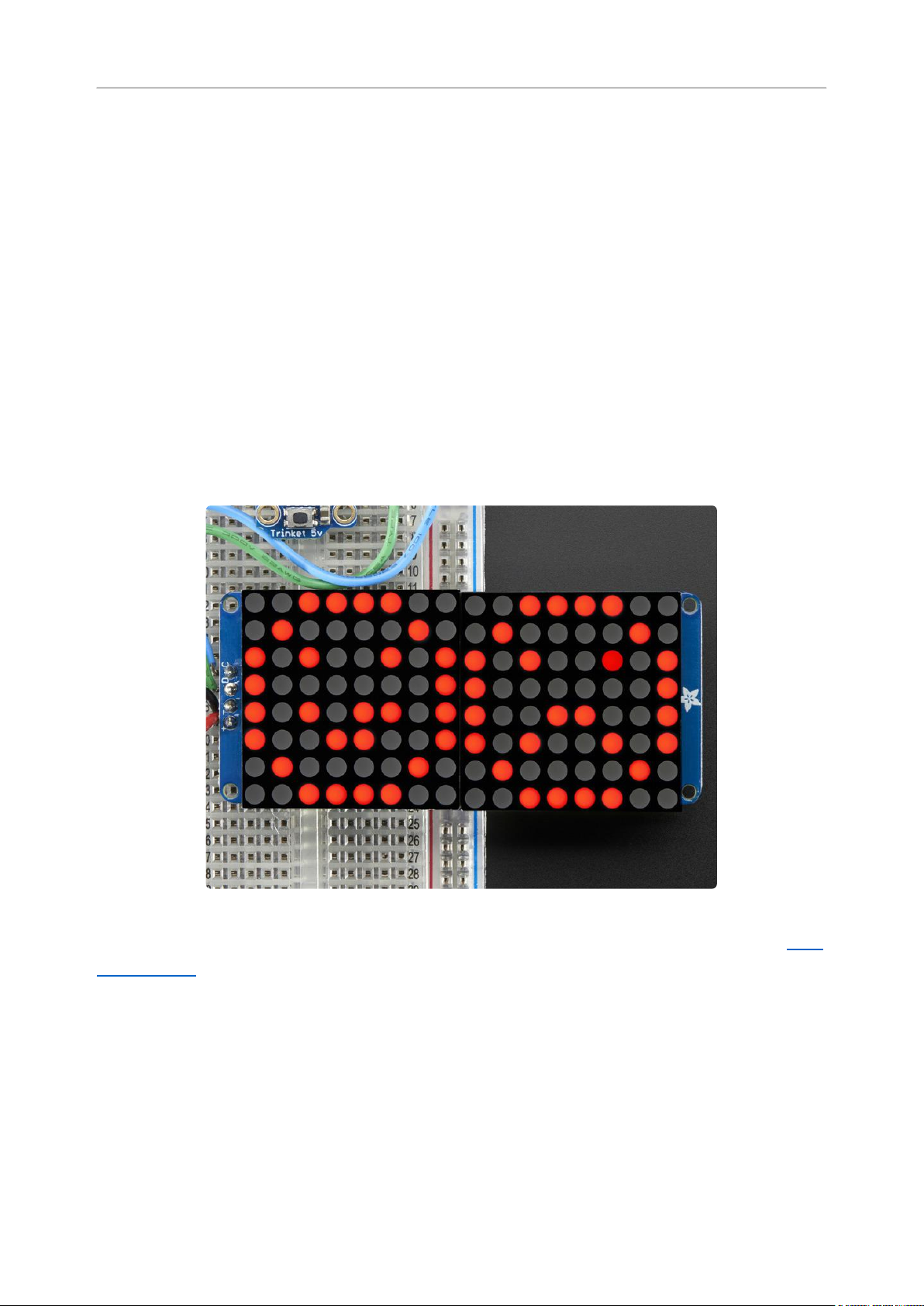
1.2" 16x8 Matrix
With the 16x8 LED Matrix we've doubled your project's matrix capacity by making it
super easy to get two separate 8x8 matrices onto one handy board! This version of
the LED backpack is designed for two of the 1.2" 8x8 matrices. They measure only
1.2"x1.2" so its a shame to use a massive array of chips to control it. This backpack
solves the annoyance of using 32 pins or a bunch of chips by having an I2C constant-
current matrix controller sit neatly on the back of the PCB. The controller chip takes
care of everything, drawing all 128 LEDs in the background. All you have to do is write
data to it using the 2-pin I2C interface. There are two address select pins so you can
select one of 8 addresses to control up to 8 of these on a single 2-pin I2C bus (as
well as whatever other I2C chips or sensors you like). The driver chip can 'dim' the
entire display from 1/16 brightness up to full brightness in 1/16th steps. It cannot dim
individual LEDs, only the entire display at once.
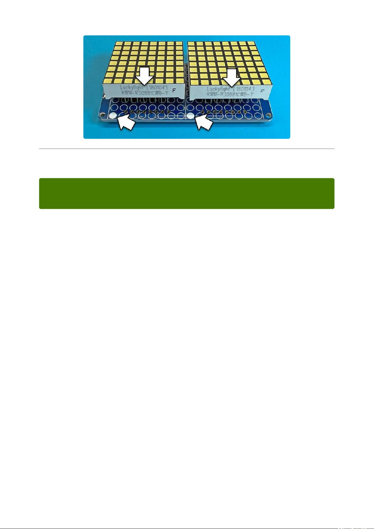
Assembling the 1.2" 16x8 backpack is nearly the same as the 1.2" 8x8, so you can follo
w that page(https://adafru.it/LAT) for directions,only difference is there’s two matrices
to install now.
The printed-on edge of the matrices face the white dots on the PCB, and there’s a
single set of address selection pads; the pair is addressed as one larger unit, not set
independently.
©Adafruit Industries Page 39 of 161
Page 40
Arduino Setup
You can use these with a 3.3v or 5v microcontroller. Just connect the VCC+ pin is
the same voltage as the logic on your microcontroller.
16x8 Matrix Software
We wrote a basic library to help you work with the 16x8 matrix backpack. The library is
written for the Arduino and will work with any Arduino as it just uses the I2C pins. The
code is very portable and can be easily adapted to any I2C-capable micro.
Wiring to the matrix is really easy
ConnectCLK to the I2C clock - on Arduino UNO thats Analog #5 (or SCL), on the
•
Leonardo its Digital #3, on the Mega its digital #21
ConnectDAT to the I2C data - on Arduino UNO thats Analog #4 (or SDA), on the
•
Leonardo its Digital #2, on the Mega its digital #20
ConnectGNDto common ground
•
ConnectVCC+to power - 5V is best but 3V also seems to work for 3V
•
microcontrollers.
Next, download theAdafruit LED Backpacklibrary and theAdafruit GFXlibrary from
the Arduino library manager.
Open up the Arduino library manager:
©Adafruit Industries Page 40 of 161
Page 41
Search for theAdafruit LED Backpacklibrary and install it
Search for theAdafruit GFXlibrary and install it
If using an earlier version of the Arduino IDE (prior to 1.8.10), also locate and install Ad
afruit_BusIO (newer versions will install this dependency automatically).
You should now be able to select the
File→Examples→Adafruit_LEDBackpack→matrix88 example sketch. Upload it to your
Arduino as usual. You should see a basic test program that goes through a bunch of
different drawing routine
We also have a great tutorial on Arduino library installation at:
http://learn.adafruit.com/adafruit-all-about-arduino-libraries-install-use(https://
adafru.it/aYM)
©Adafruit Industries Page 41 of 161
Page 42

Once you're happy that the matrix works, you can write your own sketches. The 8x8
matrix supports everything the Adafruit GFX library - drawing pixels, lines, rectancles,
circles, triangles, roundrects, and small bitmaps. For more details check out the GFX
page which will detail all of the GFX routines(https://adafru.it/aPx).
All the drawing routines only change the display memory kept by the Arduino. Don't
forget to call writeDisplay() after drawing to 'save' the memory out to the matrix via
I2C.
There are also a few small routines that are special to the matrix:
setBrightness(brighness)- will let you change the overall brightness of the entire
•
display. 0 is least bright, 15 is brightest and is what is initialized by the display
when you start. You can call this function at any time to change the brightness of
the -entire- display
blinkRate(rate) - You can blink the entire display. 0 is no blinking. 1, 2 or 3 is for
•
display blinking.You can call this function at any time to change the blink rate of
the -entire- display
©Adafruit Industries Page 42 of 161
Page 43

The default orientation for graphics
commands on this display places pixel
(0,0) at the top-left when the header is at
the left and Adafruit logo at the right. To
use the matrix as shown above (header at
top, logo at bottom), call
matrix.setRotation(3) before issuing
graphics commands.
CircuitPython Wiring and Setup
Wiring
It's easy to use LED Matrices with CircuitPython and the Adafruit CircuitPython
HT16K33(https://adafru.it/u1E) library. This module allows you to easily write
CircuitPython code to control the display.
You can use this sensor with any CircuitPython microcontroller board.
We'll cover how to wire the LED Matrix to your CircuitPython microcontroller board.
First assemble your LED Matrix.
Connect the LED Matrix to your microcontroller board as shown below.
Microcontroller 3Vto LED Matrix VIN
Microcontroller GNDto LED MatrixGND
Microcontroller SCLto LED MatrixSCL
Microcontroller SDAto LED MatrixSDA
Download Fritzing Object
https://adafru.it/IB5
©Adafruit Industries Page 43 of 161
Page 44

Library Setup
To use the LED backpackwith yourAdafruit CircuitPython(https://adafru.it/BlM)board
you'll need to install theAdafruit_CircuitPython_HT16K33(https://adafru.it/u1E) library
on your board.
First make sure you are running thelatest version of Adafruit CircuitPython(https://
adafru.it/tBa)for your board. Next you'll need to install the necessary librariesto use
the hardware--read below and carefully follow the referenced steps to find and install
these libraries from Adafruit's CircuitPython library bundle(https://adafru.it/zdx).
Bundle Install
For express boards that have extra flash storage, like the Feather/Metro M0 express
and Circuit Playground express, you can easily install the necessary libraries with Ada
fruit's CircuitPython bundle(https://adafru.it/zdx). This is an all-in-one package that
includes the necessary libraries to use the LED backpack display with CircuitPython.
For details on installing the bundle, read about CircuitPython Libraries(https://
adafru.it/ABU).
Remember for non-express boards like the Trinket M0, Gemma M0, and Feather/
Metro M0 basic you'll need to manually install the necessary libraries(https://adafru.it/
ABU) from the bundle:
adafruit_ht16k33
•
adafruit_bus_device
•
If your board supports USB mass storage, like the M0-based boards, then simply drag
the files to the board's file system.Note on boards without external SPI flash, like a
Feather M0 or Trinket/Gemma M0, you might run into issues on Mac OSX with hidden
files taking up too much space when drag and drop copying,see this page for a
workaround(https://adafru.it/u1d).
Before continuing make sure your board's lib folder or root filesystem has at least
theadafruit_ht16k33 andadafruit_bus_devicefolders/modules copied over.
©Adafruit Industries Page 44 of 161
Page 45

Python Wiring and Setup
Wiring
It's easy to use LED Matrices with Python and the Adafruit CircuitPython HT16K33(htt
ps://adafru.it/u1E) library. This library allows you to easily write Python code to control
the display.
We'll cover how to wire the LED Matrix to your Raspberry Pi. First assemble your LED
Matrix.
Since there's dozens of Linux computers/boards you can use we will show wiring for
Raspberry Pi. For other platforms, please visit the guide for CircuitPython on Linux to
see whether your platform is supported(https://adafru.it/BSN).
Connect the LED Matrix as shown below to your Raspberry Pi.
Raspberry Pi 3.3Vto LED MatrixVIN
Raspberry Pi GNDto LED MatrixGND
Raspberry Pi SCLto LED MatrixSCL
Raspberry Pi SDAto LED MatrixSDA
©Adafruit Industries Page 45 of 161
Page 46

Download Fritzing Object
https://adafru.it/IB6
Setup
You'll need to install the Adafruit_Blinka library that provides the CircuitPython
support in Python. This may also require enabling I2C on your platform and verifying
you are running Python 3. Since each platform is a little different, and Linux changes
often, please visit the CircuitPython on Linux guide to get your computer ready(https:
//adafru.it/BSN)!
Python Installation of HT16K33 Library
Once that's done, from your command line run the following command:
pip3 install adafruit-circuitpython-ht16k33
•
If your default Python is version 3 you may need to run 'pip' instead. Just make sure
you aren't trying to use CircuitPython on Python 2.x, it isn't supported!
If that complains about pip3 not being installed, then run this first to install it:
sudo apt-get install python3-pip
•
Pillow Library
We also need PIL, the Python Imaging Library, to allow using text with custom fonts.
There are several system libraries that PIL relies on, so installing via a package
manager is the easiest way to bring in everything:
sudo apt-get install python3-pil
•
That's it. You should be ready to go.
©Adafruit Industries Page 46 of 161
Page 47

CircuitPython and Python Usage
The following section will show how to control the LED backpackfrom the board's
Python prompt / REPL. You'll walk through how to control the LED display and learn
how to use the CircuitPython module built for the display.
Firstconnect to the board's serial REPL(https://adafru.it/Awz)so you are at the
CircuitPython>>>prompt.
Initialization
First you'll need to initialize the I2C bus for your board. It's really easy, first import the
necessary modules. In this case, we'll use board and MatrixBackpack16x8 .
Then just use board.I2C() to create the I2C instance using the default SCL and
SDA pins (which will be marked on the boards pins if using a Feather or similar
Adafruit board).
Then to initialize the matrix, you just pass i2c in.
import board
from adafruit_ht16k33.matrix import MatrixBackpack16x8
i2c = board.I2C()
matrix = MatrixBackpack16x8(i2c)
If you bridged the address pads on the back of the display, you could pass in the
address. The addresses for the HT16K33 can range between 0x70 and 0x77
depending on which pads you have bridged, with 0x70 being used if you haven't
bridged any of them. For instance, if you bridge only the A0 pad, you would use
0x71 like this:
matrix = MatrixBackpack16x8(i2c, address=0x71)
Setting the Brightness
You can set the brightness of the display, but changing it will set the brightness of the
entire display and not individual segments. If can be adjusted in 1/16 increments betw
een 0 and 1.0 with 1.0 being the brightest. So to set the display to half brightness, you
would use the following:
©Adafruit Industries Page 47 of 161
Page 48

display.brightness = 0.5
Setting the Blink Rate
You can set the blink rate of the display, but changing it will set the brightness of the
entire display and not individual pixels. If can be adjusted in 1/4 incrementsbetween 0
and 3with 3 being the fastest blinking. So to set the display to blink at full speed, you
would use the following:
display.blink_rate = 3
Setting Individual Pixels
To set individual pixels to on, you simply treat the matrix object as a
multidimensional list and set it to 1.
matrix[0, 0] = 1
matrix[4, 4] = 1
matrix[7, 7] = 1
Filling the Entire Matrix
To fill the entire matrix, just use the fill() function and pass in either 0 or 1 depending
on whether you want all pixels off or on. For instance, if you wanted to set everything
to on, you would use:
matrix.fill(1)
Shifting the Matrix
To shift the pixels on the matrix, there are 5 functions you can use. The main function,
called shift(), is used to shift the pixels, up, down, left, right, or even diagonally. By
passing a positive number, it will shift the pixels right/up and passing a negative
number will shift them left/down. For instance:
matrix.shift(2, 0) # shift pixels to the right by 2
matrix.shift(-1, 0) # shift pixels to the left by 1
matrix.shift(0, -3) # shift pixels down by 3
matrix.shift(-2, 2) # shift pixels left by 2 and up by 2
©Adafruit Industries Page 48 of 161
Page 49
You can pass True as a third parameter to loop all the pixels that get shifted off over
to the other side.
matrix.shift(2, 0, True) # loop pixels to the right by 2
matrix.shift(-1, 0, True) # loop pixels to the left by 1
matrix.shift(0, -3, True) # loop pixels down by 3
matrix.shift(-2, 2, True) # loop pixels left by 2 and up by 2
Additionally, there are a few convenience functions that will shift the pixels by one.
These can also be passed a value of True to loop the pixels.
matrix.shift_up() # Shift pixels up
matrix.shift_left() # Shift pixels left
matrix.shift_down() # Shift pixels down
matrix.shift_right() # Shift pixels right
matrix.shift_up(True) # Loop pixels up
matrix.shift_left(True) # Loop pixels left
matrix.shift_down(True) # Loop pixels down
matrix.shift_right(True) # Loop pixels right
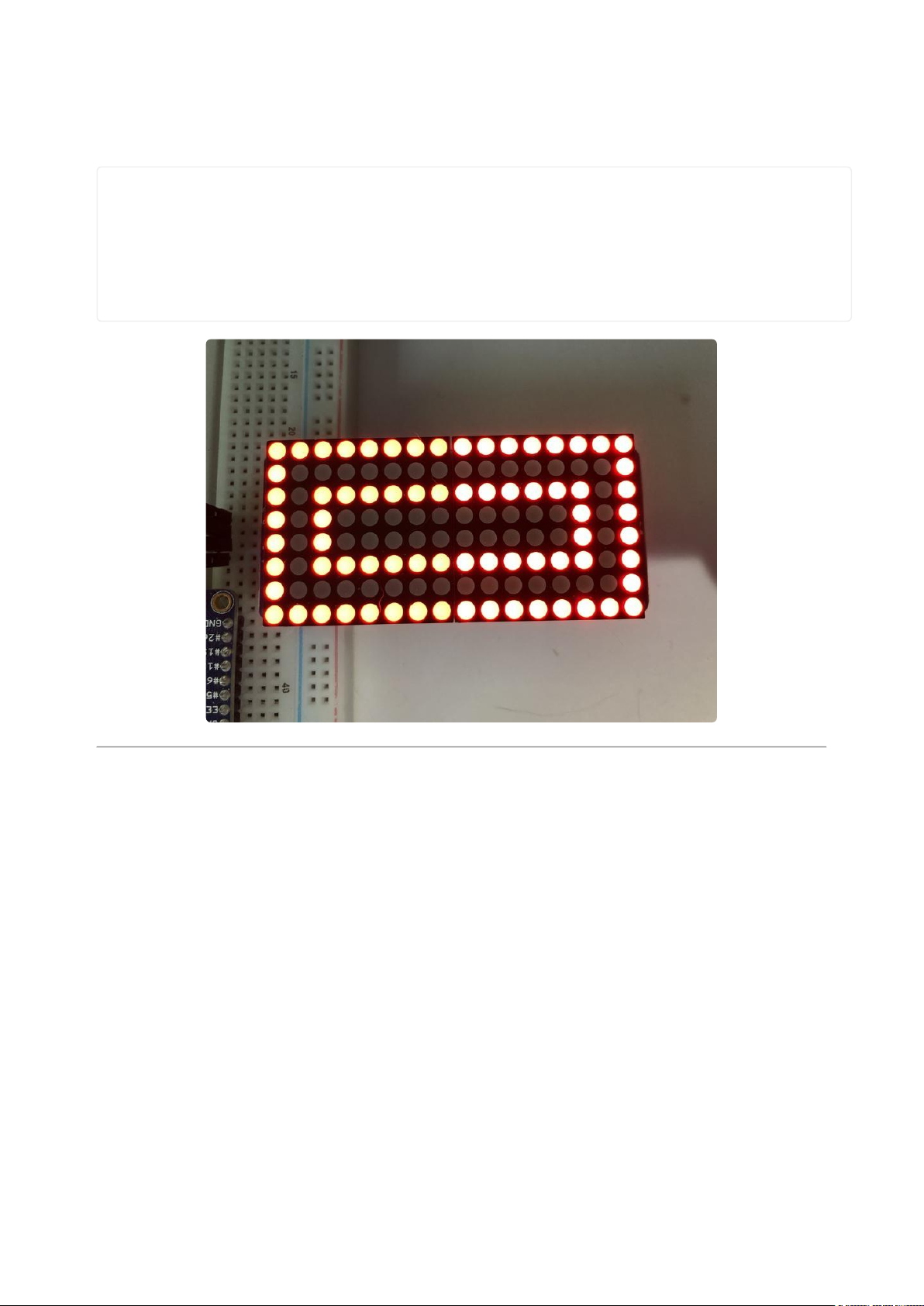
Here's what shifting a smiley face to the right looks like:
Displaying an Image (Pillow Only)
Additionally, when using with the Raspberry Pi, you can use the Pillow library to
display an image to the Matrix. The image will need to be the same exact size as the
Matrix. In this case, it should be 16x8 pixels. As an example, you can save the image
below asmyimage.png.
Download Image
https://adafru.it/ICS
©Adafruit Industries Page 49 of 161
Page 50
Then if you want to display the image calledmyimage.png, you would use something
like this:
import board
from PIL import Image
from adafruit_ht16k33 import matrix
matrix = matrix.MatrixBackpack16x8(board.I2C())
image = Image.open("myimage.png")
matrix.image(image)
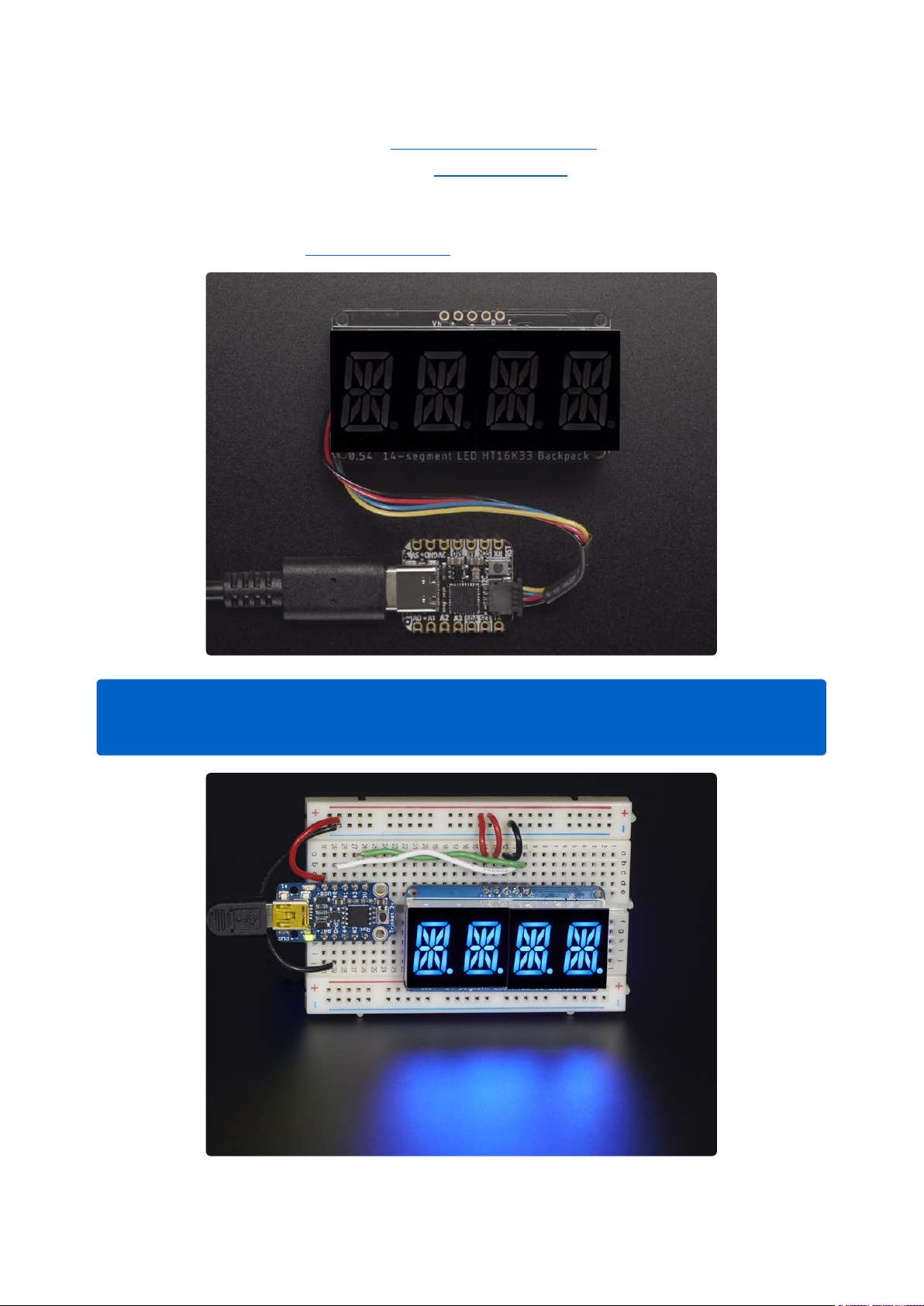
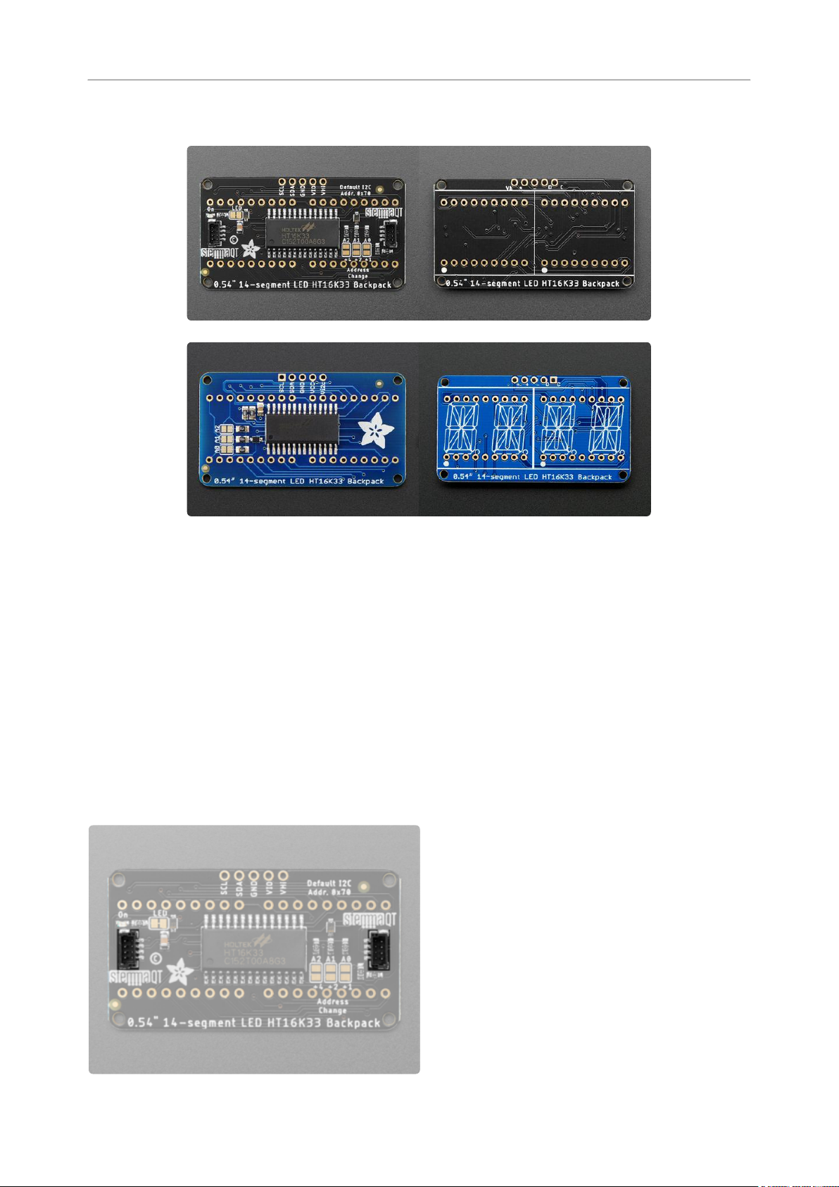
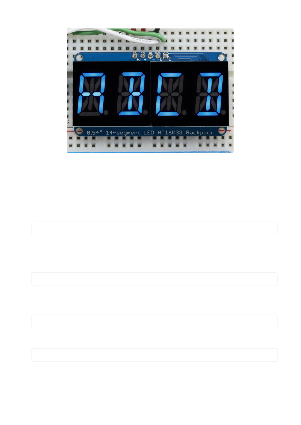
0.54" Alphanumeric Backpack
This version of the LED backpack is designed for two dual 14-segment "Alphanumeric"
displays. These 14-segment displays normally require 18 pins (4 'characters' and 14
total segments each) This backpack solves the annoyance of using 18 pins or a bunch
of chips by having an I2C constant-current matrix controller sit neatly on the back of
the PCB. The controller chip takes care of everything, drawing all the LEDs in the
background. All you have to do is write data to it using the 2-pin I2C interface.
There are three address select pins so you can select one of 8 addresses to control
up to 8 of these on a single 2-pin I2C bus (as well as whatever other I2C chips or
sensors you like). The driver chip can 'dim' the entire display from 1/16 brightness up
to full brightness in 1/16th steps. It cannot dim individual LEDs, only the entire display
at once.
©Adafruit Industries Page 50 of 161
Page 51
To get you going fast, we have revised this popular board to be the same size and
pinout as before but now with twoSTEMMA QT connectors(https://adafru.it/JqB)on
either side that are compatible with theSparkFun Qwiic(https://adafru.it/Fpw)I2C
connectors. This allows you to make solderless connections between your
development board and the HT16K33 or to chain it with a wide range of other sensors
and accessories using acompatible cable(https://adafru.it/JnB).
There are two versions of this board - the STEMMA QT version shown above, and
the original header-only version shown below. Code works the same on both!
©Adafruit Industries Page 51 of 161
Page 52
Pinouts
There are a number of features on the 0.54" Alphanumeric Backpack.
STEMMA QT Revision-Only Features
These features are only available on the STEMMA QT revision.
STEMMA QT Connectors
The default I2C address is 0x70.
TheSTEMMA QT connectors(https://
adafru.it/Ft4) provide a solder-free way to
connect this backpack to development
boards with STEMMA QT connectors, or to
other things, with various associated
accessories(https://adafru.it/Qgf).
©Adafruit Industries Page 52 of 161
Page 53
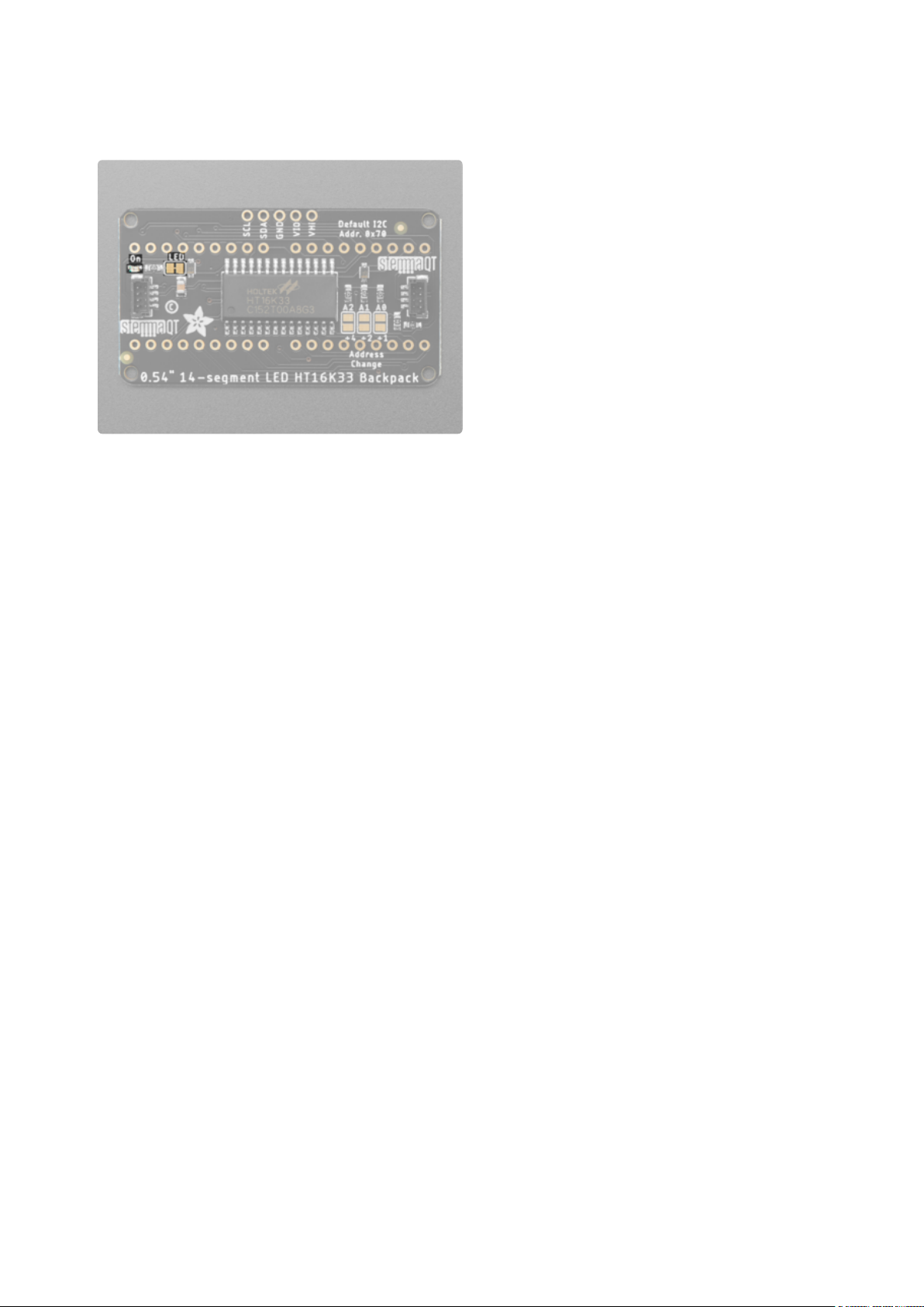
On LED and LED Jumper
On LED - On the left side of the back of
the board is a little green LED labeled On.
This LED lights up when the board is
successfully powered.
LED jumper - To the right of the On LED is
a jumper labeled LED. If you wish to
disable the On LED, you can cut the trace
between the two pads. To enable it again,
use solder to reconnect the two pads.
Original and STEMMA QT Version Features
These features are available on both versions. There is one header pin difference
between the two, which is explained in the next section. Everything else is the same.
Header Pin Through-Hole Pads
If you prefer to use a breadboard, there are through-hole header pin pads along the
top of the board in the middle.
The default I2C address is 0x70.
©Adafruit Industries Page 53 of 161
Page 54
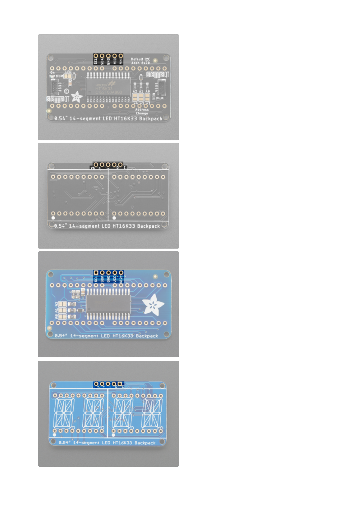
On both versions:
VIO/VCC - This is power for the backpack.
It can be 3V-5V. To power the backpack,
give it the same power as the logic level of
your microcontroller - e.g. for a 5V
microcontroller like Arduino, use 5V.
GND - This is common ground for power
and logic.
SCL - This is the I2C clock pin. Connect it
to your microcontroller I2C clock line. This
pin is level shifted so you can use 3-5V
logic, and there's a10K pullupon this pin.
SDA - This is the I2C data pin. Connect it
to your microcontroller I2C data line. This
pin is level shifted so you can use 3-5V
logic, and there's a10K pullupon this pin.
©Adafruit Industries Page 54 of 161
Page 55

On the STEMMA QT revision ONLY:
VHi - This pin allows you to provide 5V to only the 14-segment displays when
•
using a 3V device to control the backpack. If you're using a 3V device and you
want your displays to be brighter, you can maintain the 3V I2C power level, and
connect 5V to the VHi pin to make the 14-segment displays have a brighter look.
On the original version ONLY:
Vi2c - This is the I2C voltage, which sets the logic level to I2C. Connect this pin
•
to the voltage pin on your device that matches the device's logic level. For
example, if you're using a 3.3V microcontroller, connect it to 3.3V.
©Adafruit Industries Page 55 of 161
Page 56
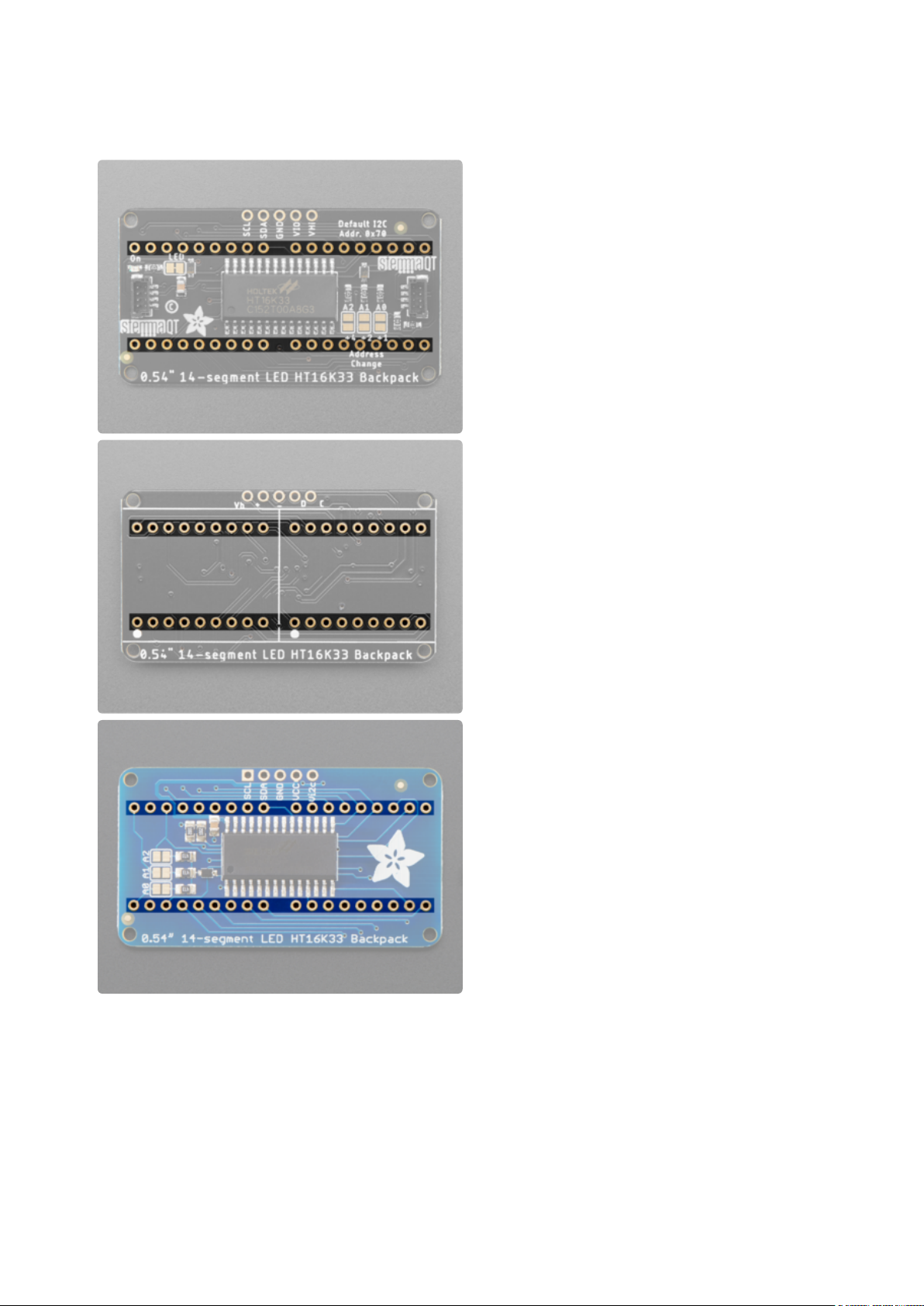
Display Pin Through-Hole Pads
These two rows of through-hole pads are
for soldering the alphanumeric LED
displays onto the backpack. See the
Assembly page(https://adafru.it/11dU) for
details on attaching the displays properly.
©Adafruit Industries Page 56 of 161
Page 57
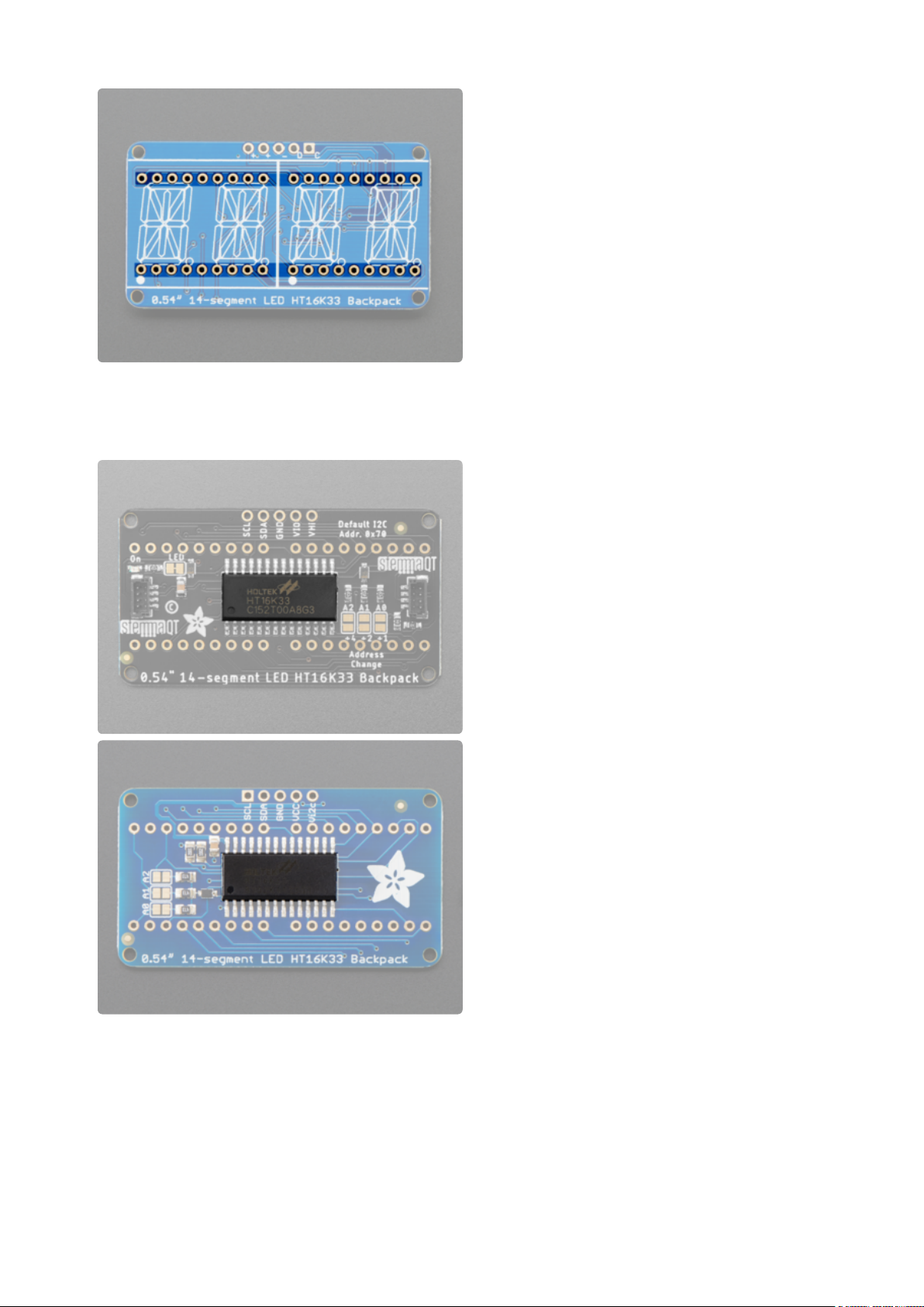
HT16K33 Matrix Driver
The chip located in the center of the back
of the backpack is the HT16K33 matrix
driver, which drives the 14-segment LED
displays.
©Adafruit Industries Page 57 of 161
Page 58

Address Jumper Pins
On the back of the board are three
address jumpers, labeled A0, A1, and A2.
These jumpers allow you to chain up to 8
of these boards on the same pair of I2C
clock and data pins. To do so, you solder
the jumpers "closed" in various
combinations by connecting the two pads.
The default I2C address is 0x70. The other
address options can be calculated by
“adding” the A0/A1/A2 to the base of
0x70.
A0 sets the lowest bit with a value of 1, A1 sets the next bit with a value of 2 and A2
sets the next bit with a value of 4. The final address is 0x70 + A2 + A1 + A0 which
would be 0x77.
So for example if A2 is soldered closed and A0 is soldered closed, the address is 0x7
0 + 4 + 1 = 0x75.
If only A0 is soldered closed, the address is 0x70 + 1 = 0x71
If only A1 is soldered closed, the address is 0x70 + 2 = 0x72
If only A2 is soldered closed, the address is 0x70 + 4 = 0x74
©Adafruit Industries Page 58 of 161
Page 59
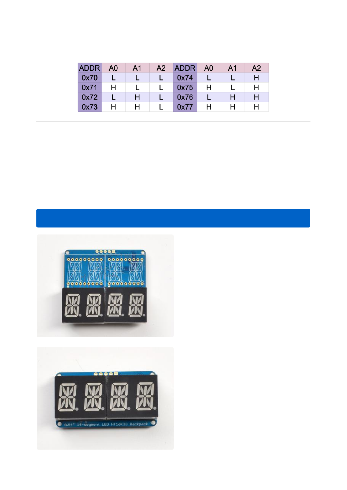
The table below shows all possible addresses, and whether the pin(s) should be high
(closed) or low (open).
Assembly
Attaching the Backpack
The assembly photos below are the original version. Assembly is the same for both
the original version and the STEMMA QT version.
This assembly is the same on the STEMMA QT version of the backpack!
When you buy a pack from Adafruit, it
comes with the fully tested and assembled
backpack as well as two dual 14-segment
display in one of the colors we provide
(say, red, yellow, blue or green). You'll
need to solder the matrix onto the
backpack but it's an easy task.
Remove the parts from packaging and
place the LED matrices OVER the
silkscreen side. DO NOT PUT THE
DISPLAY ON UPSIDE DOWN OR IT WONT
WORK!! Check the image below to make
sure the 'decimal point' dots are on the
bottom, matching the silkscreen.
©Adafruit Industries Page 59 of 161
Page 60

Turn the backpack over so it is sitting flat
on the matrix.
©Adafruit Industries Page 60 of 161
Page 61

Solder all of the pins!
©Adafruit Industries Page 61 of 161
Page 62

Clip the long pins.
©Adafruit Industries Page 62 of 161
Page 63

Attaching Header
Check your work, making sure each pin is
nicely soldered, and there's no cold solder
joints or shorted pins
Prepare the header strip:
Cut the strip to length if necessary. It will
be easier to solder if you insert it into a
breadboard - long pins down
Add the Backpack:
Place the backpack board over the pins so
that the short pins poke through the
breakout pads
©Adafruit Industries Page 63 of 161
Page 64
Solder all 5 pins!
That's it! now you're ready to run the firmware on your Arduino!
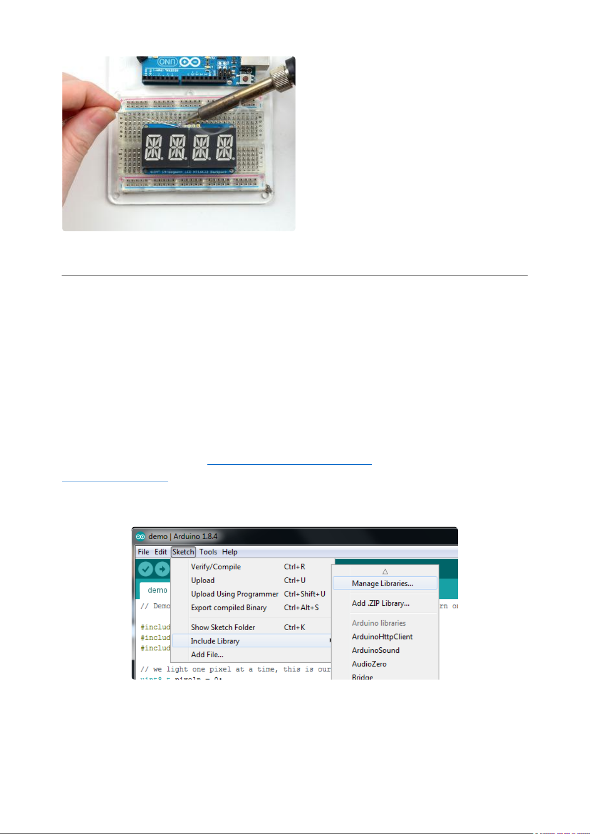
Arduino Wiring and Setup
Downloading the Arduino Library
We wrote a basic library to help you work with the alphanumeric backpack. The
library is written for the Arduino and will work with any Arduino as it just uses the I2C
pins. The code is very portable and can be easily adapted to any I2C-capable micro.
Begin by downloading our Adafruit LED Backpack library (https://adafru.it/aLI)and the
Adafruit GFX library(https://adafru.it/aJa) from the Arduino library manager.
Open up the Arduino library manager:
Search for theAdafruit LED Backpacklibrary and install it
©Adafruit Industries Page 64 of 161
Page 65

When asked to install dependencies, click Install all.
We also have a great tutorial on Arduino library installation at:
http://learn.adafruit.com/adafruit-all-about-arduino-libraries-install-use(https://
adafru.it/aYM)
You can use these with a 3.3v or 5v microcontroller. Just make sure the Vi2c pin
is the same voltage as the logic on your microcontroller.
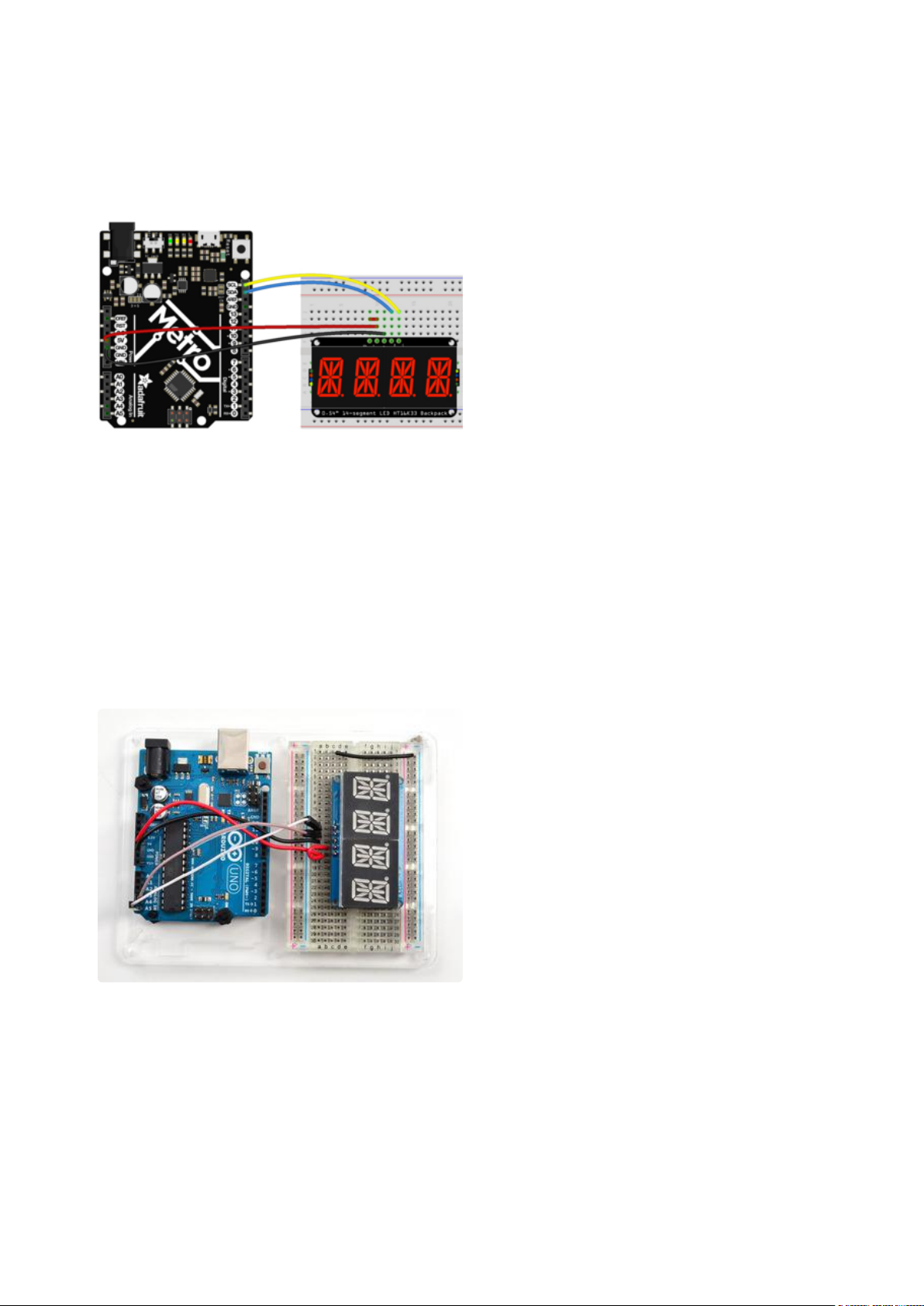
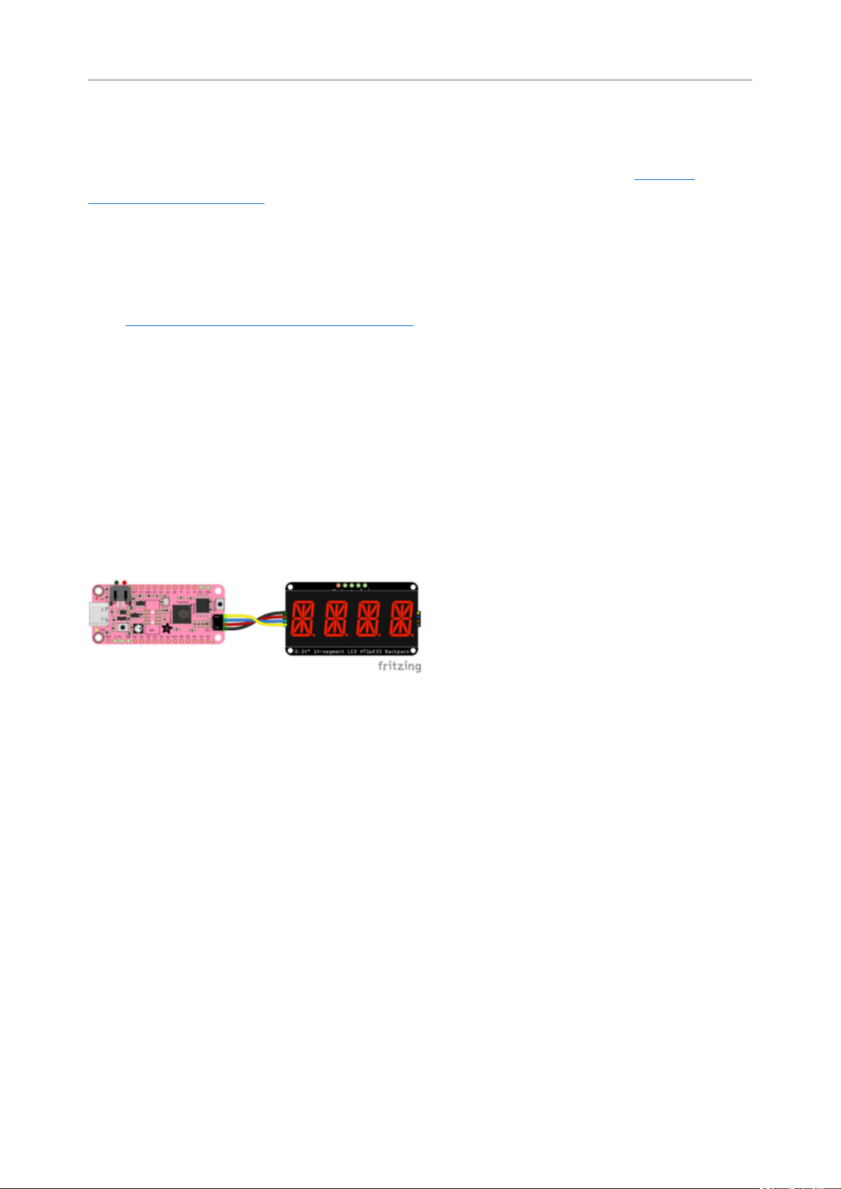
Wiring STEMMA QT Version
Here is an example of the STEMMA QT version wired to a Metro using the STEMMA
QT connector on the backpack.
Board 5Vto backpack Vio (red wire)
Board GNDto backpack GND (black wire)
Board SCLto backpack SCL (yellow wire)
Board SDAto backpack SDA (blue wire)
©Adafruit Industries Page 65 of 161
Page 66
Here is an example of the STEMMA QT version wired to a Metro using a solderless
breadboard. This example also includes how to wire up the VHi pin, which makes the
LEDs appear brighter.
Board 5Vto backpack Vio (long red wire)
Board GNDto backpack GND (black wire)
Board SCLto backpack SCL (yellow wire)
Board SDAto backpack SDA (blue wire)
Backpack VIO to backpack VHi (short red
wire)
Wiring Original Version
Connect CLK to the I2C clock - on Arduino
UNO thats Analog #5 (or SCL), on the
Leonardo it's Digital #3, on the Mega it's
digital #21
Connect DAT to the I2C data - on Arduino
UNO thats Analog #4 (or SDA), on the
Leonardo it's Digital #2, on the Mega it's
digital #20
Connect GND to common ground
Connect VCC+ to power - 5V is best but
3V will work if that's all you've got (it will
be dimmer)
Connect Vi2c to your microcontroller's
logic level (3-5V) - If you're using an
Arduino, this is almost certainly 5V. If its a
3V Arduino such as a Due, connect it to 3V
Both Vi2c and Vcc MUST be connected to
3 to 5VDC! Vcc is for the LED driver power,
Vi2c is what sets the logic level for
communication to the chip.
©Adafruit Industries Page 66 of 161
Page 67
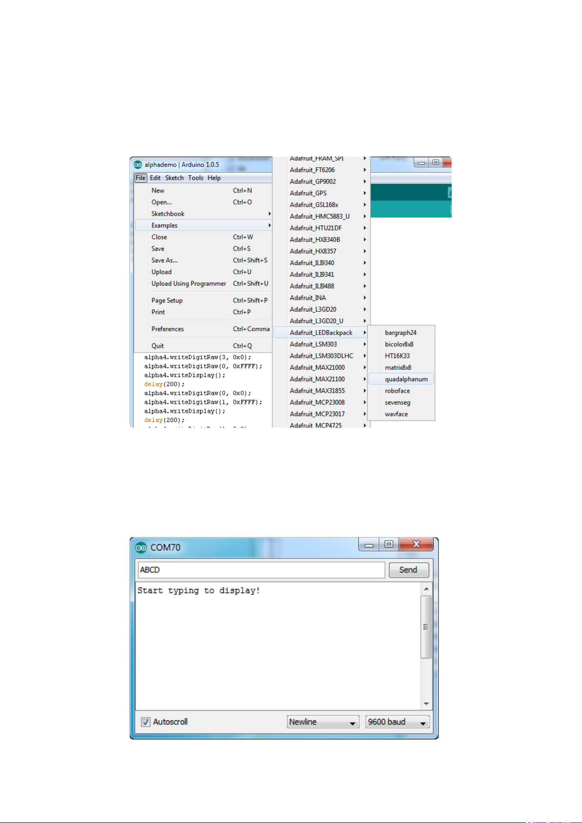
Load Demo
Restart the Arduino IDE and load up the File→Adafruit_LEDBackpack→quadalphanum
demo
Upload to your Arduino, and open up the Serial console at 9600 baud speed. You'll
see each digit light up all the segments, then the display will scroll through the 'font
table' showing every character that it knows how to display. Finally, you'll get a notice
to start typing into the serial console. Type a message and hit return, you'll see it
scroll onto the display!
©Adafruit Industries Page 67 of 161
Page 68
Library Reference
For the quad displays, we have a special object that can handle ascii data for easy
printing.
You can create the object with
Adafruit_AlphaNum4 alpha4 = Adafruit_AlphaNum4();
There's no arguments or pins because the backpacks use the fixed I2C pins.
By default, the address is 0x70, but you can pass in the I2C address used when you
initialize the display with begin
alpha4.begin(0x70); // pass in the address
Next up, the segments can be turned on/off for each digit by writing the 'raw' bitmap
you want, for example, all the LEDs off on digit #3 is
alpha4.writeDigitRaw(3, 0x0);
All the segments on for digit #0 is
alpha4.writeDigitRaw(0, 0x3FFF);
This is the segment map:
©Adafruit Industries Page 68 of 161
Page 69
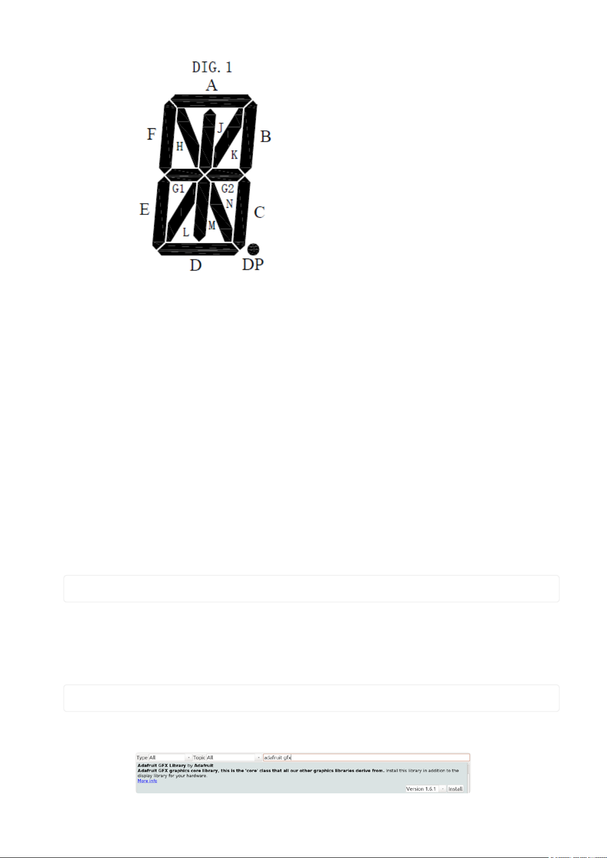
the 16 bit digit you pass in for raw image has this mapping:
0 DP N M L K J H G2 G1 F E D C B A
The first bit isn't used, you can make it 0 or 1
To turn on just the A segment, use 0x0001
To turn on just the G1 segment, use 0x0040
ASCII data
If you're just looking to print 'text' you can use our font table, just pass in an ASCII
character!
For example, to set digit #0 to A call:
alpha4.writeDigitAscii(0, 'A')
Writing Data
Don't forget to 'write' the data to the display with
alpha4.writeDisplay();
That's what actually 'sets' the data onto the LEDs!
©Adafruit Industries Page 69 of 161
Page 70
CircuitPython Wiring and Setup
It's easy to use LED AlphaNumeric Displays with CircuitPython and the Adafruit
CircuitPython HT16K33(https://adafru.it/u1E) library. This module allows you to easily
write CircuitPython code to control the display.
You can use this backpack with any CircuitPython microcontroller board.
First assemble your AlphaNumeric Display(https://adafru.it/11dU).
Wiring STEMMA QT Version
Here is an example of the STEMMA QT version wired to a Feather RP2040 using the
STEMMA QT connector on the backpack.
Board 3.3Vto backpack Vio (red wire)
Board GNDto backpack GND (black wire)
Board SCLto backpack SCL (yellow wire)
Board SDAto backpack SDA (blue wire)
Here is an example of the STEMMA QT version wired to a Feather RP2040 using a
solderless breadboard. This example also includes how to wire up the VHi pin, which
makes the LEDs appear brighter.
©Adafruit Industries Page 70 of 161
Page 71
Board 5Vto backpack Vio (red wire
connected along the bottom of the
Feather)
Board GNDto backpack GND (black wire)
Board SCLto backpack SCL (yellow wire)
Board SDAto backpack SDA (blue wire)
Board USB to backpack VHi (red wire
connected along the top of the Feather)
Wiring Original Version
Connect the AlphaNumeric Display to your microcontroller board as shown below.
Microcontroller 3Vto AlphaNumeric
Display I2C VIN
Microcontroller 3Vto AlphaNumeric
DisplayVIN
Microcontroller GNDto AlphaNumeric
DisplayGND
Microcontroller SCLto AlphaNumeric
DisplaySCL
Microcontroller SDAto AlphaNumeric
DisplaySDA
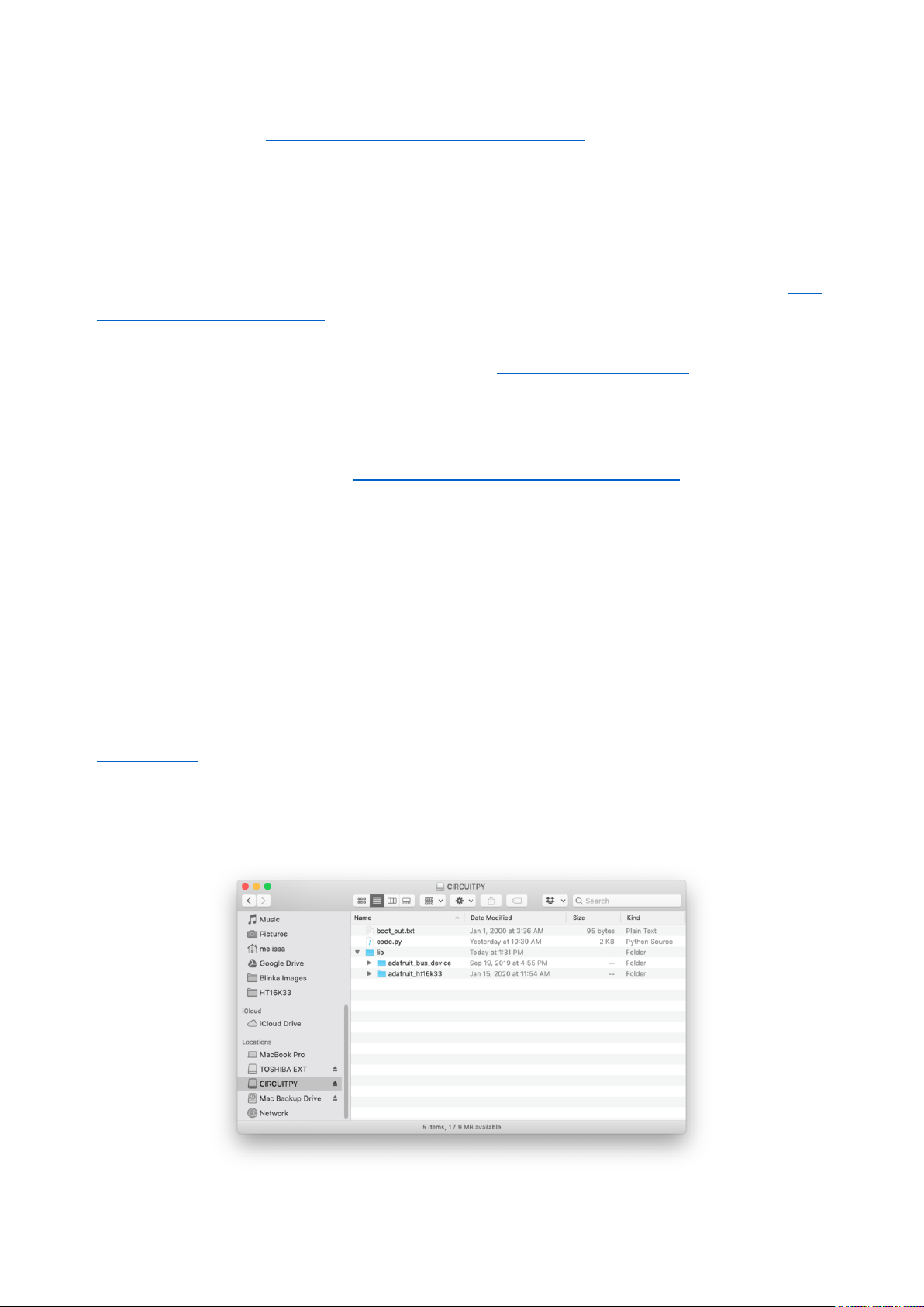
HT16K33 Library Installation
To use with CircuitPython, you need to first install the HT16K33 library, and its
dependencies, into thelibfolder on yourCIRCUITPYdrive. Then you need to
updatecode.pywith the example script.
Thankfully, you can do this in one go. In the example below, click theDownload
Project Bundlebutton below to download the necessary libraries and thecode.pyfile
in a zip file. Extract the contents of the zip file, and copy theentirelibfolderand thec
ode.pyfile to yourCIRCUITPYdrive.
©Adafruit Industries Page 71 of 161
Page 72
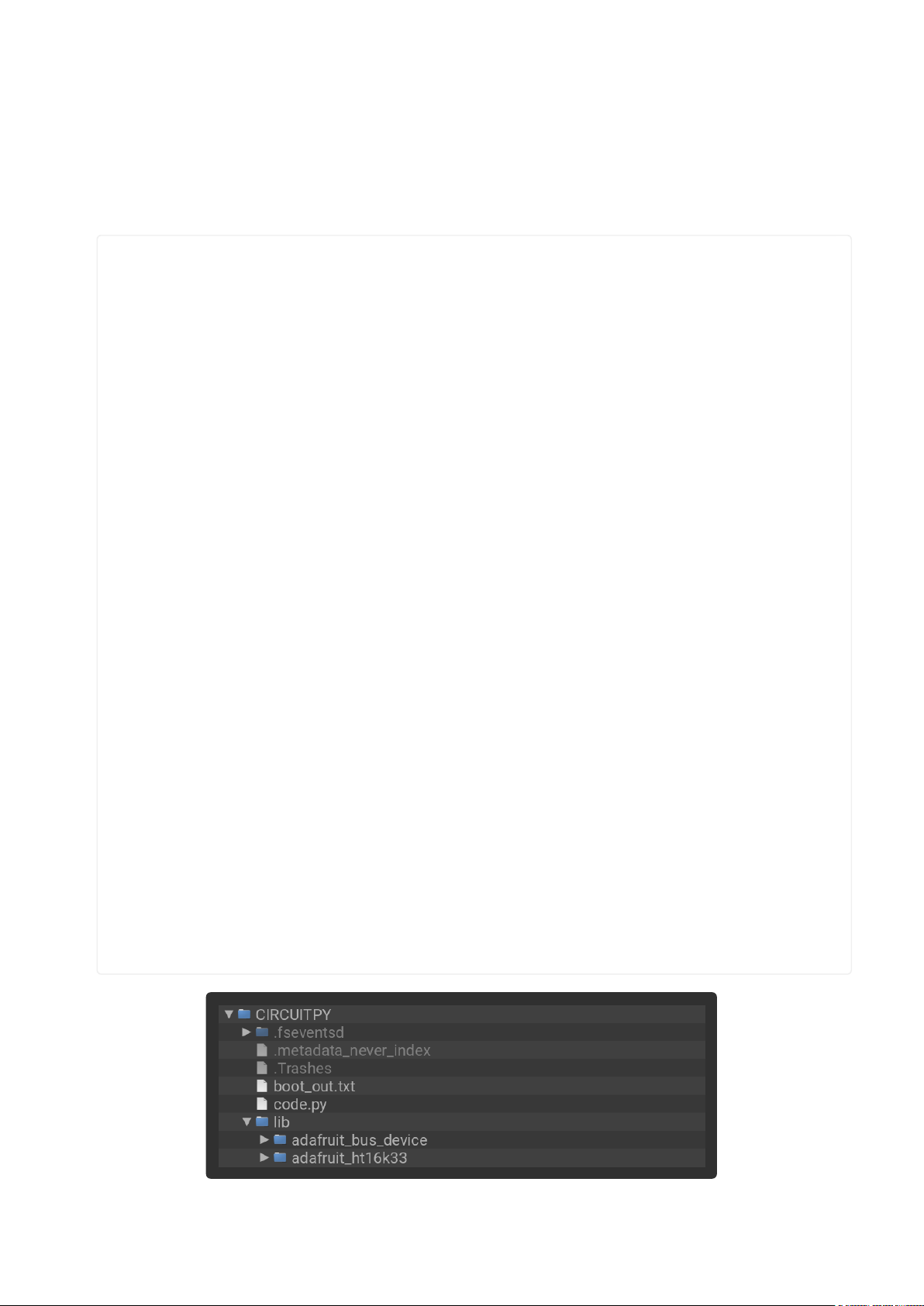
YourCIRCUITPY/libfolder should contain the following folders:
adafruit_bus_device/
•
adafruit_ht16k33/
•
# SPDX-FileCopyrightText: 2022 Kattni Rembor for Adafruit Industries
# SPDX-License-Identifier: MIT
import time
import board
from adafruit_ht16k33 import segments
# Create the display object.
# Display connected to STEMMA QT connector.
display = segments.Seg14x4(board.STEMMA_I2C())
# Display connected to I2C pins.
# display = segments.Seg14x4(board.I2C())
# This section displays four 0's across the display. The code shows four
# different ways to use the set_digit_raw function. Each is labeled below.
# 16-bit Hexadecimal number
display.set_digit_raw(0, 0x2D3F)
time.sleep(0.2)
# 16-bit Binary number
display.set_digit_raw(1, 0b0010110100111111)
time.sleep(0.2)
# 8-bit Binary Tuple
display.set_digit_raw(2, (0b00101101, 0b00111111))
time.sleep(0.2)
# 8-bit Hexadecimal List
display.set_digit_raw(3, [0x2D, 0x3F])
time.sleep(0.2)
# Delay between.
time.sleep(2)
# Scroll "Hello, world!" across the display. Setting the loop parameter to false
allows you to
# tell the marquee function to run only once. By default, marquee loops
indefinitely.
display.marquee("Hello, world!", loop=False)
# Delay between.
time.sleep(2)
# Scroll special characters, uppercase and lowercase letters, and numbers across
# the display in a loop. This section will continue to run indefinitely.
display.marquee("".join(chr(character) for character in range(ord("!"), ord("z") +
1)))
©Adafruit Industries Page 72 of 161
Page 73
Python Wiring and Setup
Wiring
It's easy to use AlphaNumeric Displays with Python and the Adafruit CircuitPython
HT16K33(https://adafru.it/u1E) library. This library allows you to easily write Python
code to control the display.
This section will cover how to wire the AlphaNumeric Display to your Raspberry Pi.
First assemble your AlphaNumeric Display.
Since there's dozens of Linux computers/boards you can use, this guide will just show
wiring for Raspberry Pi. For other platforms, please visit the guide for CircuitPython on
Linux to see whether your platform is supported(https://adafru.it/BSN).
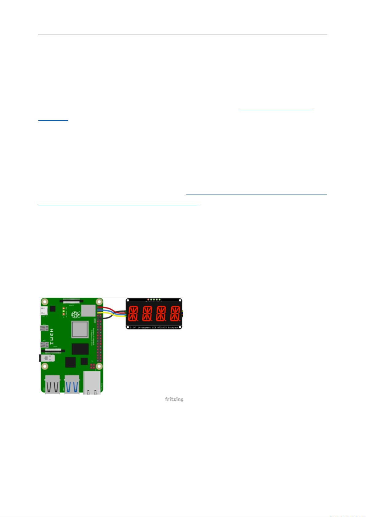
Connect the AlphaNumeric Display as shown below to your Raspberry Pi.
Wiring STEMMA QT Version
Here is an example of wiring the STEMMA QT version of the backpack to a Raspberry
Pi using the STEMMA QT connector.
Pi GNDto backpack GND (black wire)
Pi 3.3Vto backpack VIO (red wire)
Pi SDAto backpack SDA (blue wire)
Pi SCLto backpack SCL (yellow wire)
Here is an example of wiring the STEMMA QT version of the backpack using a
solderless breadboard. This example also includes how to wire up the VHi pin, which
makes the LEDs appear brighter.
©Adafruit Industries Page 73 of 161
Page 74

Wiring Original Version
Pi GNDto backpack GND (black wire)
Pi 3.3Vto backpack VIO (lower red wire)
Pi SDAto backpack SDA (blue wire)
Pi SCLto backpack SCL (yellow wire)
Pi 5V to backpack VHi (upper red wire)
Raspberry Pi 3.3Vto AlphaNumeric
Display I2C VIN
Raspberry Pi 3.3Vto AlphaNumeric
DisplayVIN
Raspberry Pi GNDto AlphaNumeric
DisplayGND
Raspberry Pi SCLto AlphaNumeric
DisplaySCL
Raspberry Pi SDAto AlphaNumeric
DisplaySDA
Setup
You'll need to install the Adafruit_Blinka library that provides the CircuitPython
support in Python. This may also require enabling I2C on your platform and verifying
you are running Python 3. Since each platform is a little different, and Linux changes
often, please visit the CircuitPython on Linux guide to get your computer ready(https:
//adafru.it/BSN)!
Python Installation of HT16K33 Library
Once that's done, from your command line run the following command:
pip3 install adafruit-circuitpython-ht16k33•
©Adafruit Industries Page 74 of 161
Page 75

If your default Python is version 3 you may need to run 'pip' instead. Just make sure
you aren't trying to use CircuitPython on Python 2.x, it isn't supported!
If that complains about pip3 not being installed, then run this first to install it:
sudo apt-get install python3-pip
•
Pillow Library
You also need PIL, the Python Imaging Library, to allow using text with custom fonts.
There are several system libraries that PIL relies on, so installing via a package
manager is the easiest way to bring in everything:
sudo apt-get install python3-pil
•
That's it. You should be ready to go.
CircuitPython and Python Usage
The following section will show how to control the LED backpackfrom the board's
Python prompt / REPL. You'll walk through how to control the LED display and learn
how to use the CircuitPython module built for the display.
Firstconnect to the board's serial REPL(https://adafru.it/Awz)so you are at the
CircuitPython>>>prompt.
Initialization
First you'll need to initialize the I2C bus for your board. It's really easy, first import the
necessary modules. In this case, you'll use board and Seg14x4 .
Then just use board.I2C() to create the I2C instance using the default SCL and
SDA pins (which will be marked on the boards pins if using a Feather or similar
Adafruit board).
Then to initialize the display, you just pass i2c in.
import board
from adafruit_ht16k33.segments import Seg14x4
©Adafruit Industries Page 75 of 161
Page 76

i2c = board.I2C()
display = Seg14x4(i2c)
If you bridged the address pads on the back of the display, you could pass in the
address. The addresses for the HT16K33 can range between 0x70 and 0x77
depending on which pads you have bridged, with 0x70 being used if you haven't
bridged any of them. For instance, if you bridge only the A0 pad, you would use
0x71 like this:
display = Seg14x4(i2c, address=0x71)
If you intend to chain multiple displays together, you will need to alter the address of
subsequent boards by bridging the address pins in various combinations(https://
adafru.it/11eg). If you have an unsoldered board, and a board with the A0 pad solder-
bridged, you would initialise the two displays as follows.
display = Seg14x4(i2c, address=(0x70, 0x71))
To add further displays, ensure the address is different on all of them(https://adafru.it/
11eg), and initialise it the same way as above, but add more comma-separated
addresses to the address=() tuple.
Setting the Brightness
You can set the brightness of the display, but changing it will set the brightness of the
entire display and not individual segments. If can be adjusted in 1/16 increments betw
een 0 and 1.0 with 1.0 being the brightest. So to set the display to half brightness, you
would use the following:
display.brightness = 0.5
Setting the Blink Rate
You can set the blink rate of the display, but changing it will set the brightness of the
entire display and not individual segments. If can be adjusted in 1/4 increments betwe
en 0 and 3 with 3 being the fastest blinking. So to set the display to blink at full
speed, you would use the following:
display.blink_rate = 3
©Adafruit Industries Page 76 of 161
Page 77

Printing Text
To print text to the display, you just use the print function. So if you want to print
ABCD, you would use the following:
display.print("ABCD")
Printing Numbers
Printing numbers is done similar to printing text, except without the quotes, though
you can still print numbers in a string as well.
display.print(1234)
Printing Hexidecimal Values
To print hexidecimal values, you use the print_hex function:
display.print_hex(0x1A2B)
Setting Individual Characters
To set individual characters, you simply treat the display object as a list and set it
tothe value that you would like.
display[0] = '1'
display[1] = '2'
display[2] = 'A'
display[3] = 'B'
Setting Individual Segments
To set individual segments to turn on or off, you would use the set_digit_raw function
to pass the digit that you want to change and the bitmask. This can be really useful
for creating your own characters. The bitmask corresponds to the following diagram.
The highest bit is not used, so an X represents that spot to indicate that.
©Adafruit Industries Page 77 of 161
Page 78

The bitmask is a 16-bit number that can be passed in as a single Hexidecimal,
Decimal, or binary number. It can also be passed in as a list or tuple containing 2
separate 8-bit numbers. Here are some of the ways to set the digits. All of these
different methods create a box with an X in the center:
display.set_digit_raw(0, 0x2D3F)
display.set_digit_raw(1, 0b0010110100111111)
display.set_digit_raw(2, (0b00101101, 0b00111111))
display.set_digit_raw(3, [0x2D, 0x3F])
©Adafruit Industries Page 78 of 161
Page 79

Filling all Segments
To fill the entire display, just use the fill() function and pass in either 0 or 1 depending
on whether you want all segments off or on. For instance, if you wanted to set
everything to on, you would use:
display.fill(1)
Scrolling Display Manually
If you want to scroll the displayed data to the left, you can use the scroll()
function. You can pass in the number of places that you want to scroll. The right-most
digit will remain unchanged and you will need to set that manually. After scrolling, you
will need to call the show function. For example if you wanted to print an A and then
scroll it over to spaces, you would do the following.
display.print("A")
display.scroll(2)
display[3] = " "
display.show()
Displaying an Automatic Scrolling Marquee
To make displaying long text easier, you can use the marquee function. You just pass
it the full string. Optionally, you can pass it the amount of delay between each
character:
display.marquee("This is a really long string ")
©Adafruit Industries Page 79 of 161
Page 80

By default it is 0.25 seconds, but you can change this by providing a second
parameter. You can optionally pass False for a third parameter if you would not like
to have it loop. So if you wanted each character to display for half a second and didn't
want it to loop, you would use the following:
display.marquee('This is a really long string ', 0.5, False)
Full Example
Click Download Project Bundle below to download a full examplecode.py and
necessary libraries to run it.
# SPDX-FileCopyrightText: 2022 Kattni Rembor for Adafruit Industries
# SPDX-License-Identifier: MIT
import time
import board
from adafruit_ht16k33 import segments
# Create the display object.
# Display connected to STEMMA QT connector.
display = segments.Seg14x4(board.STEMMA_I2C())
# Display connected to I2C pins.
# display = segments.Seg14x4(board.I2C())
# This section displays four 0's across the display. The code shows four
# different ways to use the set_digit_raw function. Each is labeled below.
# 16-bit Hexadecimal number
display.set_digit_raw(0, 0x2D3F)
time.sleep(0.2)
# 16-bit Binary number
display.set_digit_raw(1, 0b0010110100111111)
time.sleep(0.2)
# 8-bit Binary Tuple
display.set_digit_raw(2, (0b00101101, 0b00111111))
time.sleep(0.2)
# 8-bit Hexadecimal List
display.set_digit_raw(3, [0x2D, 0x3F])
time.sleep(0.2)
# Delay between.
time.sleep(2)
# Scroll "Hello, world!" across the display. Setting the loop parameter to false
allows you to
# tell the marquee function to run only once. By default, marquee loops
indefinitely.
display.marquee("Hello, world!", loop=False)
# Delay between.
time.sleep(2)
# Scroll special characters, uppercase and lowercase letters, and numbers across
# the display in a loop. This section will continue to run indefinitely.
display.marquee("".join(chr(character) for character in range(ord("!"), ord("z") +
1)))
©Adafruit Industries Page 80 of 161
Page 81
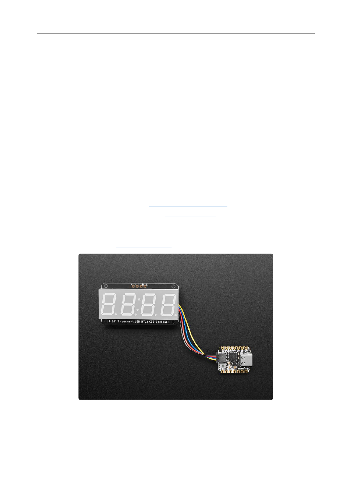
0.56" 7-Segment Backpack
This version of the LED backpack is designed for these big bright 7-segment displays.
These 7-segment displays normally require 13 pins (5 'characters' and 8 total
segments each) This backpack solves the annoyance of using 13 pins or a bunch of
chips by having an I2C constant-current matrix controller sit neatly on the back of the
PCB. The controller chip takes care of everything, drawing all the LEDs in the
background. All you have to do is write data to it using the 2-pin I2C interface. There
are three address select pins so you can select one of 8 addresses to control up to 8
of these on a single 2-pin I2C bus (as well as whatever other I2C chips or sensors you
like). The driver chip can 'dim' the entire display from 1/16 brightness up to full
brightness in 1/16th steps. It cannot dim individual LEDs, only the entire display at
once.
To get you going fast, we have revised this popular board to be the same size and
pinout as before but now with two STEMMA QT connectors(https://adafru.it/JqB)on
either side that are compatible with theSparkFun Qwiic(https://adafru.it/Fpw)I2C
connectors. This allows you to make solderless connections between your
development board and the HT16K33 or to chain it with a wide range of other sensors
and accessories using acompatible cable(https://adafru.it/JnB).
©Adafruit Industries Page 81 of 161
Page 82
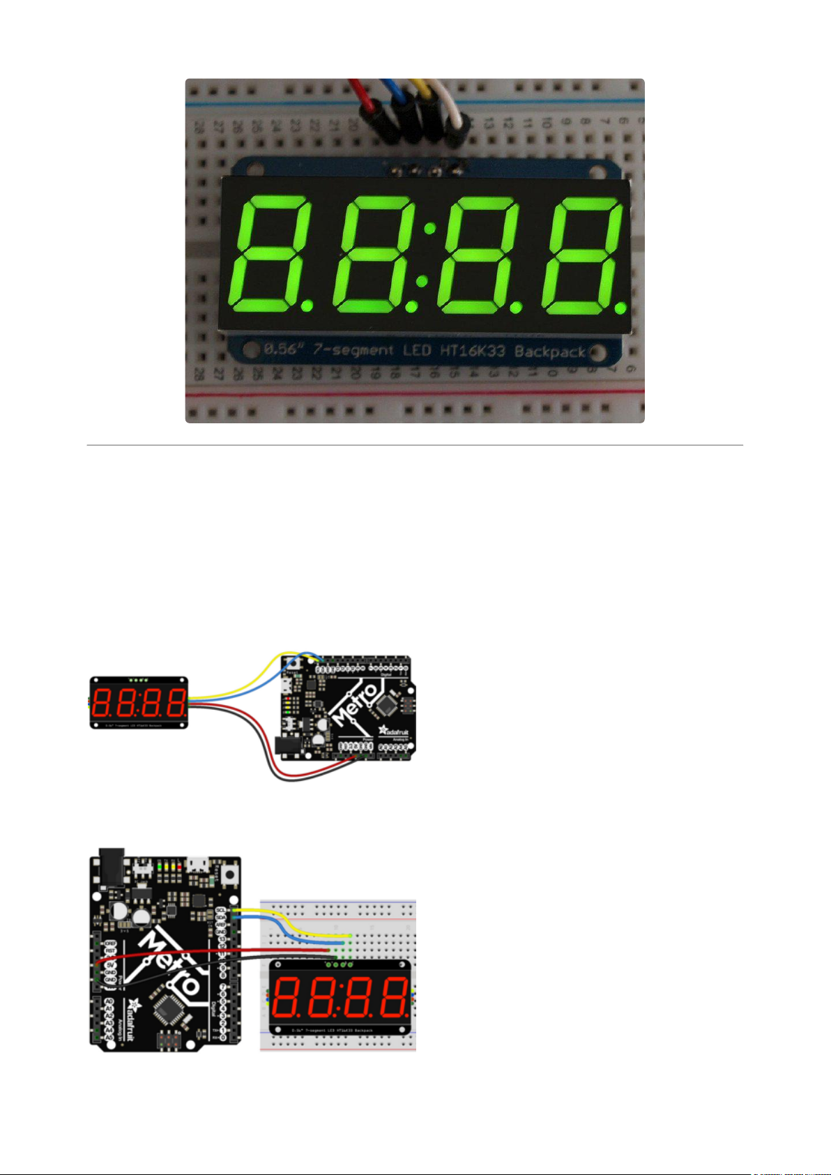
Assembly and Arduino Wiring
For the STEMMA QT version, you can solder the headers on, or you can simply use a
STEMMA QT cable!
Backpack + (VCC) to microcontroller 5V (if
using a board with 5V logic, otherwise use
3V for boards with 3V logic) (red wire)
Backpack - (GND) to microcontroller GND
(black wire)
Backpack D (SDA) to microcontroller SDA
(blue wire)
Backpack C (SCL) to microcontroller SCL
(yellow wire)
©Adafruit Industries Page 82 of 161
Page 83
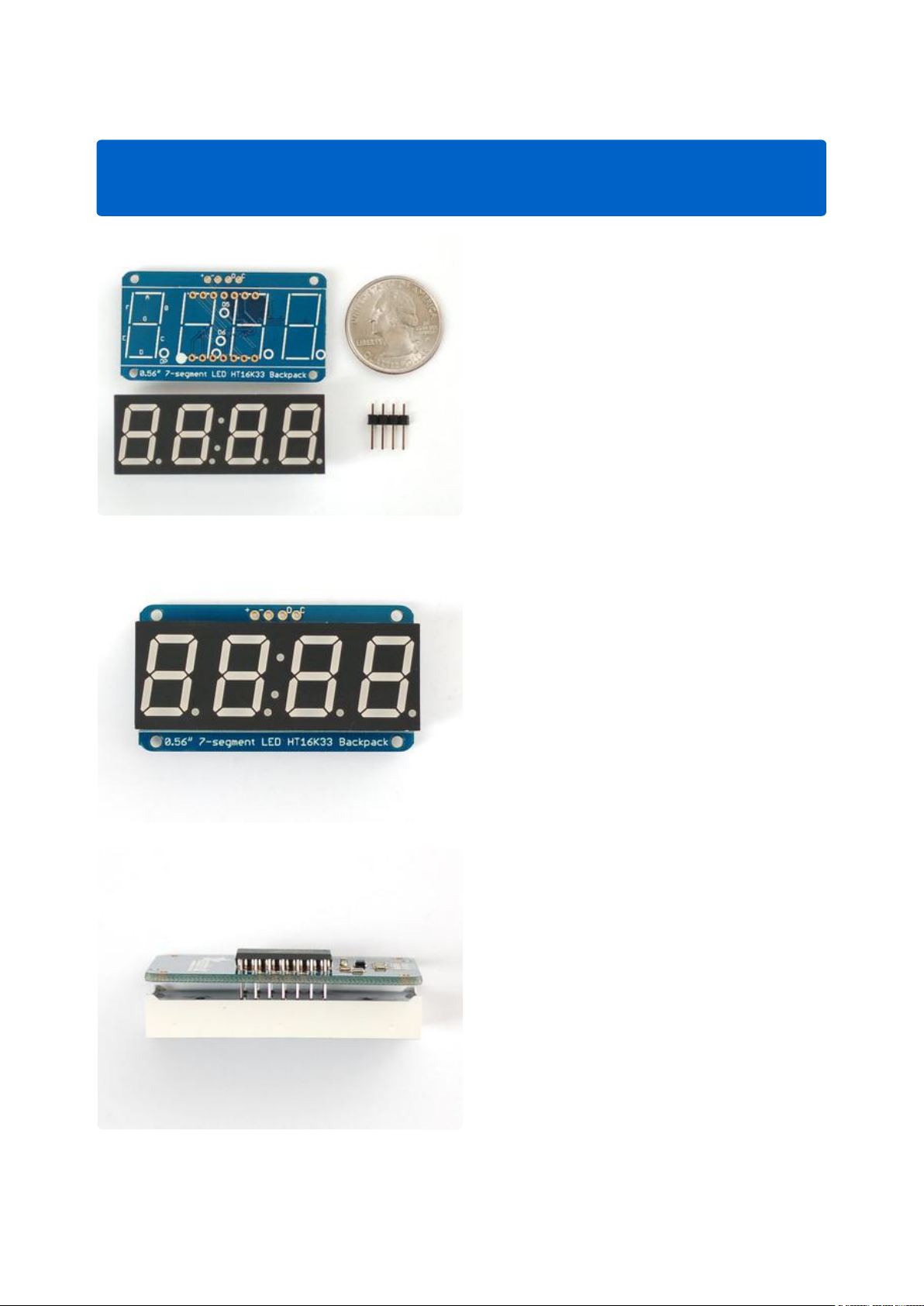
To assemble the LED backpack, follow along below.
Soldering the 7-segment display is the same for the STEMMA QT version and the
original version.
When you buy a pack from Adafruit, it
comes with the fully tested and assembled
backpack as well as a 7-segment display in
one of the colors we provide (say, red,
yellow, blue or green). You'll need to
solder the matrix onto the backpack but
it's an easy task.
Remove the parts from packaging and
place the LED matrix OVER the silkscreen
side.DO NOT PUT THE DISPLAY ON
UPSIDE DOWN OR IT WONT WORK!!
Check the image below to make sure the
'decimal point' dots are on the bottom,
matching the silkscreen.
Turn the backpack over so it is sitting flat
on the matrix.
©Adafruit Industries Page 83 of 161
Page 84
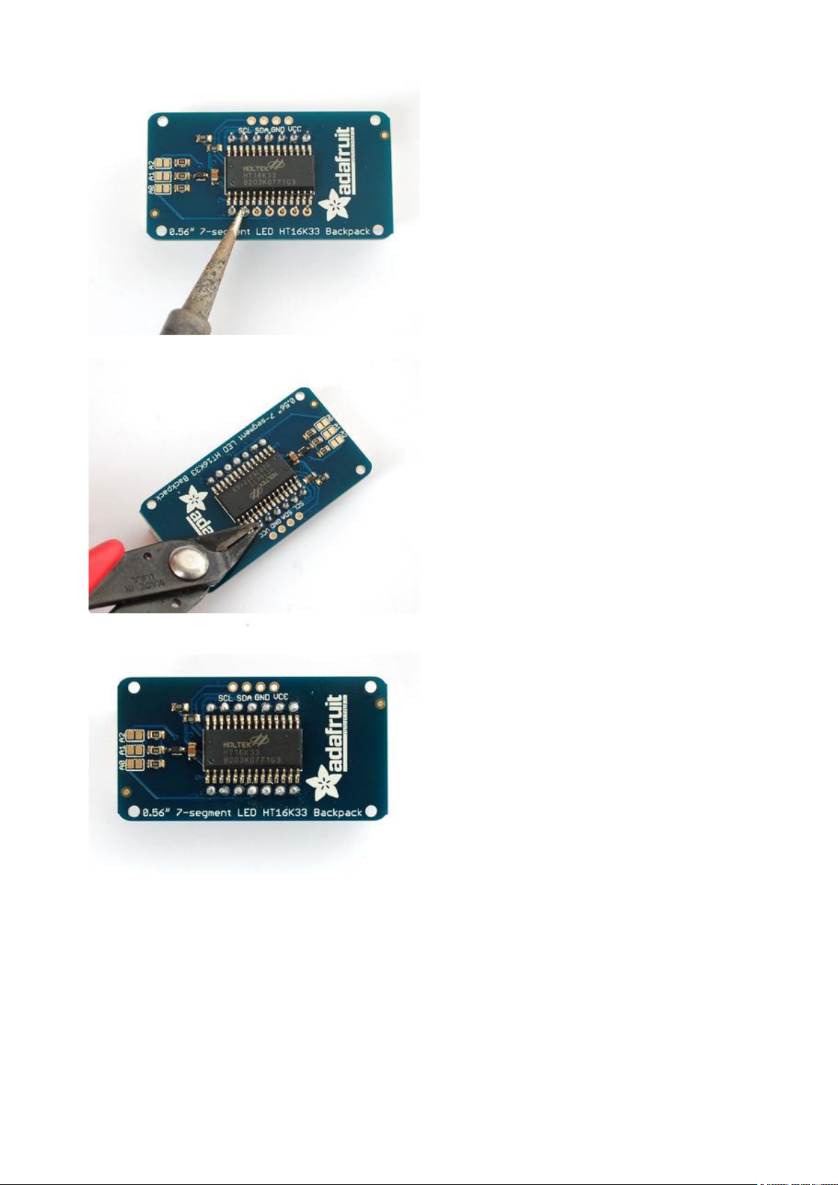
Solder all 14 pins.
Clip the long pins.
©Adafruit Industries Page 84 of 161
Page 85
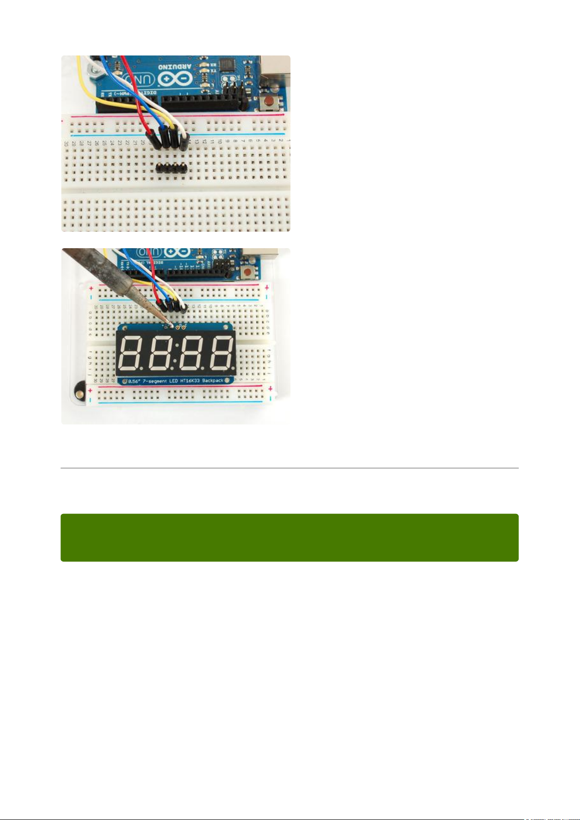
Now you're ready to wire it up to a
microcontroller. We'll assume you want to
use a 4pin header. You can also of course
solder wires directly. Place a 4-pin piece of
header with the LONG pins down into the
breadboard.
Place the soldered backpack on top of the
header and Solder 'em!
That's it! now you're ready to run the firmware!
Arduino Setup
You can use these with a 3.3v or 5v microcontroller. Just connect the VCC+ pin is
the same voltage as the logic on your microcontroller.
Seven-Segment Backpack Firmware
We wrote a basic library to help you work with the 7-segment backpack. The library is
written for the Arduino and will work with any Arduino as it just uses the I2C pins. The
code is very portable and can be easily adapted to any I2C-capable micro.
Wiring to the matrix is really easy
Connect CLK to the I2C clock - on Arduino UNO thats Analog #5 (or SCL), on the
•
Leonardo it's Digital #3, on the Mega it's digital #21
©Adafruit Industries Page 85 of 161
Page 86
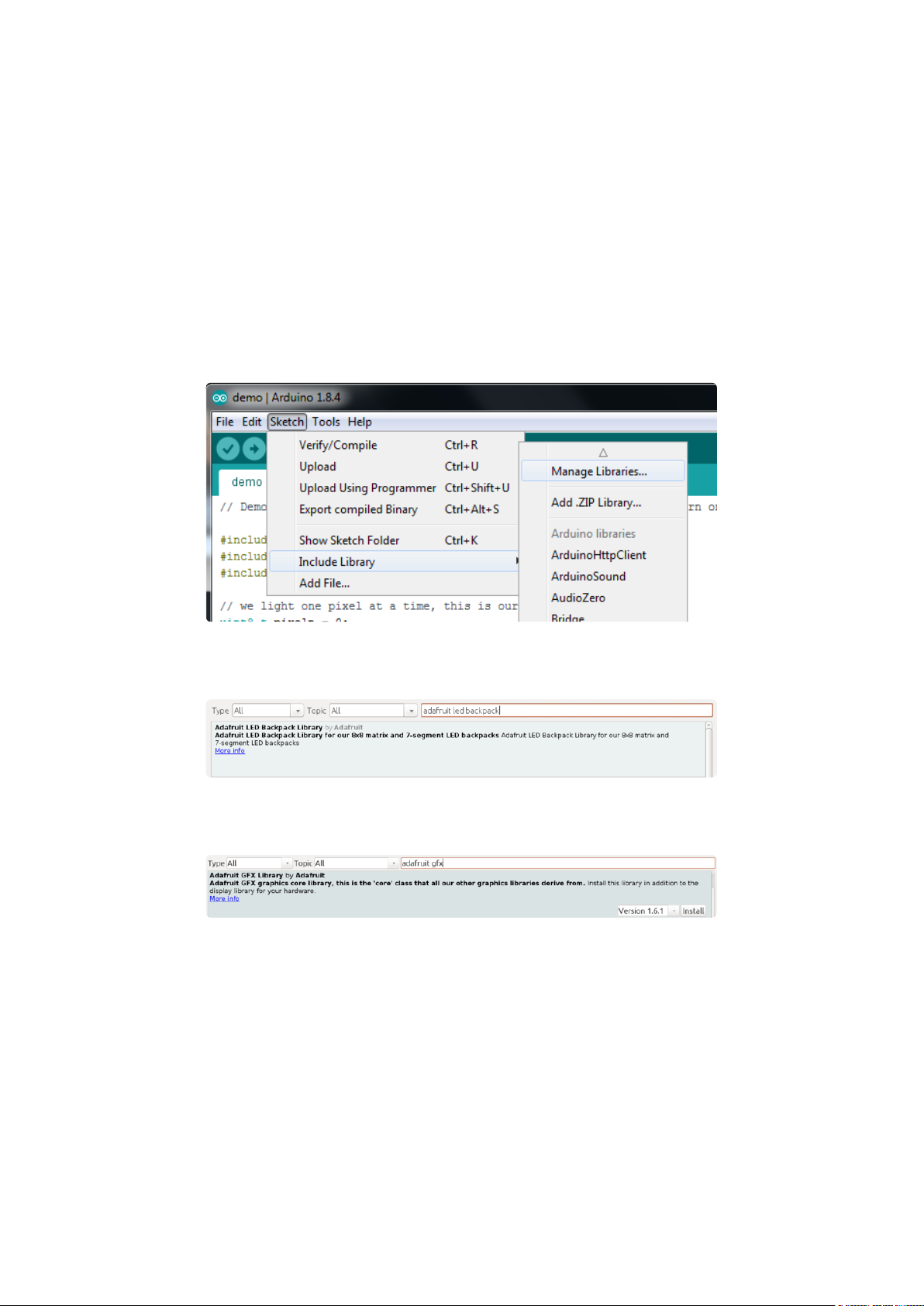
Connect DAT to the I2C data - on Arduino UNO thats Analog #4 (or SDA), on the
•
Leonardo it's Digital #2, on the Mega it's digital #20
Connect GND to common ground
•
Connect VCC+ to power - 5V is best but 3V also seems to work for 3V
•
microcontrollers.
Next, download theAdafruit LED Backpacklibrary and theAdafruit GFXlibrary from
the Arduino library manager.
Open up the Arduino library manager:
Search for theAdafruit LED Backpacklibrary and install it
Search for theAdafruit GFXlibrary and install it
If using an earlier version of the Arduino IDE (prior to 1.8.10), also locate and install Ad
afruit_BusIO (newer versions will install this dependency automatically).
Once you've restarted you should be able to select the
File→Examples→Adafruit_LEDBackpack→sevenseg example sketch. Upload it to your
Arduino as usual. You should see a basic test program that goes through a bunch of
different routines.
©Adafruit Industries Page 86 of 161
Page 87
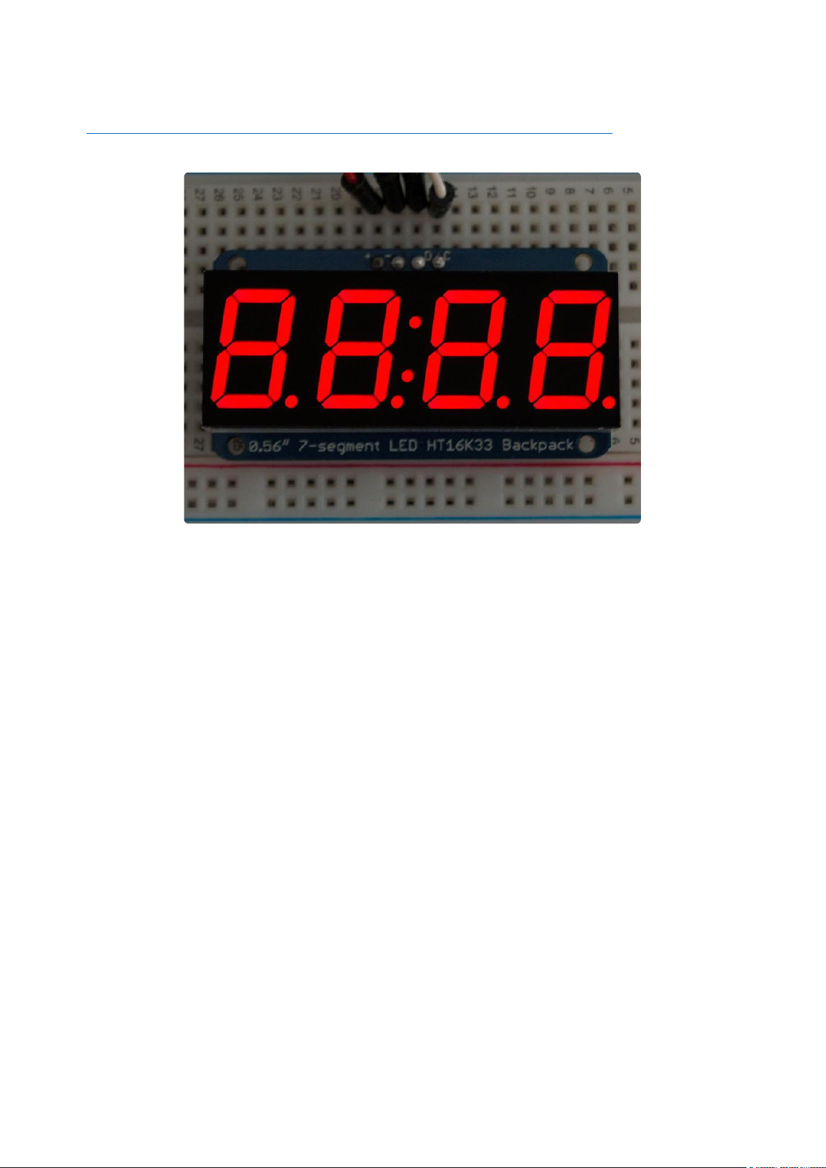
We also have a great tutorial on Arduino library installation at:
http://learn.adafruit.com/adafruit-all-about-arduino-libraries-install-use(https://
adafru.it/aYM)
Once you're happy that the matrix works, you can write your own sketches.
There's a few ways you can draw to the display. The easiest is to just call print - just
like you do with Serial
print(variable,HEX) - this will print a hexidecimal number, from 0000 up to FFFF
•
print(variable,DEC) or print(variable) - this will print a decimal integer, from 0000
•
up to 9999
If you need more control, you can call writeDigitNum(location, number) - this will write
the number (0-9) to a single location. Location #0 is all the way to the left, location #2
is the colon dots so you probably want to skip it, location #4 is all the way to the right.
If you want a decimal point, call writeDigitNum(location, number, true) which will paint
the decimal point. To draw the colon, usedrawColon(true or false)
If you wanteven more control, you can call writeDigitRaw(location,bitmask) to draw a
raw 8-bit mask (as stored in a uint8_t) to that location.
All the drawing routines only change the display memory kept by the Arduino. Don't
forget to call writeDisplay() after drawing to 'save' the memory out to the matrix via
I2C.
©Adafruit Industries Page 87 of 161
Page 88

There are also a few small routines that are special to the backpack:
setBrightness(brightness)- will let you change the overall brightness of the entire
•
display. 0 is least bright, 15 is brightest and is what is initialized by the display
when you start
blinkRate(rate) - You can blink the entire display. 0 is no blinking. 1, 2 or 3 is for
•
display blinking.
CircuitPython Wiring and Setup
Wiring
It's easy to use LED 7-Segment Displays with CircuitPython and the Adafruit
CircuitPython HT16K33(https://adafru.it/u1E) library. This module allows you to easily
write CircuitPython code to control the display.
You can use this sensor with any CircuitPython microcontroller board.
We'll cover how to wire the 7-Segment Display to your CircuitPython microcontroller
board. First assemble your 7-Segment Display.
Connect the 7-Segment Display to your microcontroller board as shown below.
©Adafruit Industries Page 88 of 161
Page 89
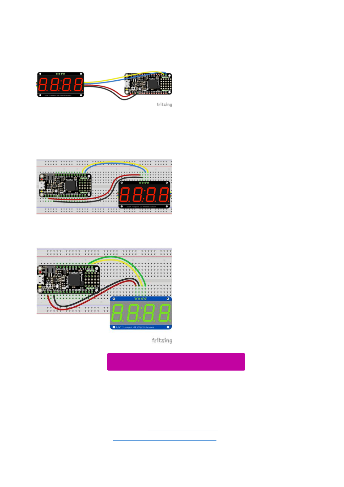
Microcontroller 3Vto 7-Segment Display
VIN (red wire)
Microcontroller GNDto 7-Segment Display
GND (black wire)
Microcontroller SCLto 7-Segment Display
SCL (yellow wire)
Microcontroller SDAto 7-Segment Display
SDA (blue wire)
Download Fritzing Object
https://adafru.it/ICk
Library Setup
To use the LED backpackwith yourAdafruit CircuitPython(https://adafru.it/BlM)board
you'll need to install theAdafruit_CircuitPython_HT16K33(https://adafru.it/u1E) library
on your board.
©Adafruit Industries Page 89 of 161
Page 90

First make sure you are running thelatest version of Adafruit CircuitPython(https://
adafru.it/tBa)for your board. Next you'll need to install the necessary librariesto use
the hardware--read below and carefully follow the referenced steps to find and install
these libraries from Adafruit's CircuitPython library bundle(https://adafru.it/zdx).
Bundle Install
For express boards that have extra flash storage, like the Feather/Metro M0 express
and Circuit Playground express, you can easily install the necessary libraries with Ada
fruit's CircuitPython bundle(https://adafru.it/zdx). This is an all-in-one package that
includes the necessary libraries to use the LED backpack display with CircuitPython.
For details on installing the bundle, read about CircuitPython Libraries(https://
adafru.it/ABU).
Remember for non-express boards like the Trinket M0, Gemma M0, and Feather/
Metro M0 basic you'll need to manually install the necessary libraries(https://adafru.it/
ABU) from the bundle:
adafruit_ht16k33
•
adafruit_bus_device
•
If your board supports USB mass storage, like the M0-based boards, then simply drag
the files to the board's file system.Note on boards without external SPI flash, like a
Feather M0 or Trinket/Gemma M0, you might run into issues on Mac OSX with hidden
files taking up too much space when drag and drop copying,see this page for a
workaround(https://adafru.it/u1d).
Before continuing make sure your board's lib folder or root filesystem has at least
theadafruit_ht16k33 andadafruit_bus_devicefolders/modules copied over.
©Adafruit Industries Page 90 of 161
Page 91
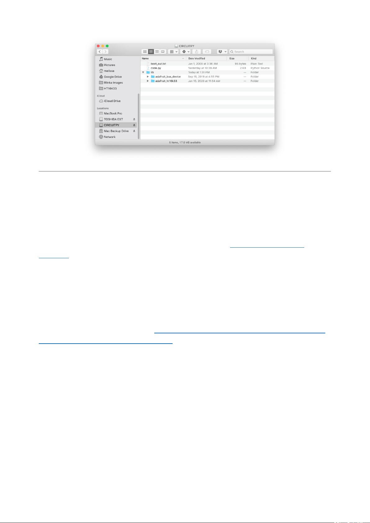
Python Wiring and Setup
Wiring
It's easy to use 7-Segment Displays with Python and the Adafruit CircuitPython
HT16K33(https://adafru.it/u1E) library. This library allows you to easily write Python
code to control the display.
We'll cover how to wire the 7-Segment Display to your Raspberry Pi. First assemble
your 7-Segment Display.
Since there's dozens of Linux computers/boards you can use we will show wiring for
Raspberry Pi. For other platforms, please visit the guide for CircuitPython on Linux to
see whether your platform is supported(https://adafru.it/BSN).
Connect the 7-Segment Display as shown below to your Raspberry Pi.
©Adafruit Industries Page 91 of 161
Page 92

Raspberry Pi 3.3Vto 7-Segment Display
VIN (red wire)
Raspberry Pi GNDto 7-Segment Display
GND (black wire)
Raspberry Pi SCLto 7-Segment Display
SCL (yellow wire)
Raspberry Pi SDAto 7-Segment Display
SDA (blue wire)
Download Fritzing Object
https://adafru.it/ICl
Setup
You'll need to install the Adafruit_Blinka library that provides the CircuitPython
support in Python. This may also require enabling I2C on your platform and verifying
you are running Python 3. Since each platform is a little different, and Linux changes
©Adafruit Industries Page 92 of 161
Page 93

often, please visit the CircuitPython on Linux guide to get your computer ready(https:
//adafru.it/BSN)!
Python Installation of HT16K33 Library
Once that's done, from your command line run the following command:
pip3 install adafruit-circuitpython-ht16k33
•
If your default Python is version 3 you may need to run 'pip' instead. Just make sure
you aren't trying to use CircuitPython on Python 2.x, it isn't supported!
If that complains about pip3 not being installed, then run this first to install it:
sudo apt-get install python3-pip
•
Pillow Library
We also need PIL, the Python Imaging Library, to allow using text with custom fonts.
There are several system libraries that PIL relies on, so installing via a package
manager is the easiest way to bring in everything:
sudo apt-get install python3-pil
•
That's it. You should be ready to go.
CircuitPython and Python Usage
The following section will show how to control the LED backpackfrom the board's
Python prompt / REPL. You'll walk through how to control the LED display and learn
how to use the CircuitPython module built for the display.
Firstconnect to the board's serial REPL(https://adafru.it/Awz)so you are at the
CircuitPython>>>prompt.
©Adafruit Industries Page 93 of 161
Page 94

Initialization
First you'll need to initialize the I2C bus for your board. It's really easy, first import the
necessary modules. In this case, we'll use board and Seg7x4 .
Then just use board.I2C() to create the I2C instance using the default SCL and
SDA pins (which will be marked on the boards pins if using a Feather or similar
Adafruit board).
Then to initialize the display, you just pass i2c in.
import board
from adafruit_ht16k33.segments import Seg7x4
i2c = board.I2C()
display = Seg7x4(i2c)
If you bridged the address pads on the back of the display, you could pass in the
address. The addresses for the HT16K33 can range between 0x70 and 0x77
depending on which pads you have bridged, with 0x70 being used if you haven't
bridged any of them. For instance, if you bridge only the A0 pad, you would use
0x71 like this:
display = Seg7x4(i2c, address=0x71)
Setting the Brightness
You can set the brightness of the display, but changing it will set the brightness of the
entire display and not individual segments. If can be adjusted in 1/16 increments betw
een 0 and 1.0 with 1.0 being the brightest. So to set the display to half brightness, you
would use the following:
display.brightness = 0.5
Setting the Blink Rate
You can set the blink rate of the display, but changing it will set the brightness of the
entire display and not individual segments. If can be adjusted in 1/4 increments betwe
en 0 and 3 with 3 being the fastest blinking. So to set the display to blink at full
speed, you would use the following:
©Adafruit Industries Page 94 of 161
Page 95

display.blink_rate = 3
Printing Text
To print text to the display, you just use the print function. For the 7-segment display,
valid characters are 0-9, letters A-F, a period, and a hyphen. So if we want to print
ABCD, we would use the following:
display.print("ABCD")
Printing Numbers
Printing numbers is done similar to printing text, except without the quotes, though
you can still print numbers in a string as well.
display.print(1234)
Printing Hexidecimal Values
To print hexidecimal values, you use the print_hex function:
display.print_hex(0x1A2B)
Setting Individual Characters
To set individual characters, you simply treat the display object as a list and set it
tothe value that you would like.
display[0] = '1'
display[1] = '2'
display[2] = 'A'
display[3] = 'B'
Setting Individual Segments
To set individual segments to turn on or off, you would use the set_digit_raw function
to pass the digit that you want to change and the bitmask. This can be really useful
for creating your own characters. The bitmask corresponds to the following diagram:
©Adafruit Industries Page 95 of 161
Page 96
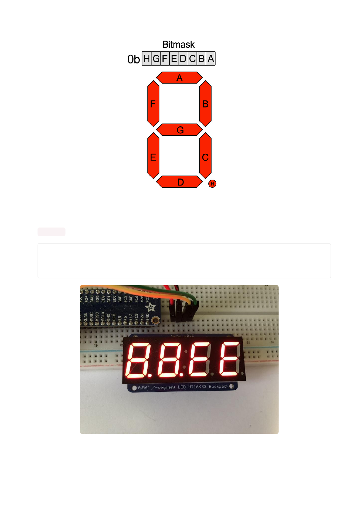
The bitmask is a single 8-bit number that can be passed in as a single Hexidecimal,
Decimal, or binary number. This will use a couple different methods to display
8.8.EE :
display.set_digit_raw(0, 0xFF)
display.set_digit_raw(1, 0b11111111)
display.set_digit_raw(2, 0x79)
display.set_digit_raw(3, 0b01111001)
©Adafruit Industries Page 96 of 161
Page 97

Filling all Segments
To fill the entire display, just use the fill() function and pass in either 0 or 1 depending
on whether you want all segments off or on. For instance, if you wanted to set
everything to on, you would use:
display.fill(1)
Scrolling Display Manually
If you want to scroll the displayed data to the left, you can use the scroll()
function. You can pass in the number of places that you want to scroll. The right-most
digit will remain unchanged and you will need to set that manually. After scrolling, you
will need to call the show function. For example if you wanted to print an A and then
scroll it over to spaces, you would do the following.
display.print("A")
display.scroll(2)
display[3] = " "
display.show()
Displaying the Colon
There are a couple of different ways to display a colon on the 7-segment display. The
first and easiest way is to use the print function:
display.print("12:30")
The other way to control it is to access the colon with the colon property and set it to
True or False :
display.colon = False
Displaying an Automatic Scrolling Marquee
To make displaying long text easier, we've added a marquee function. You just pass it
the full string. Optionally, you can pass it the amount of delay between each
character. This may be useful for displaying an IP address, a phone number, or other
numeric data:
©Adafruit Industries Page 97 of 161
Page 98
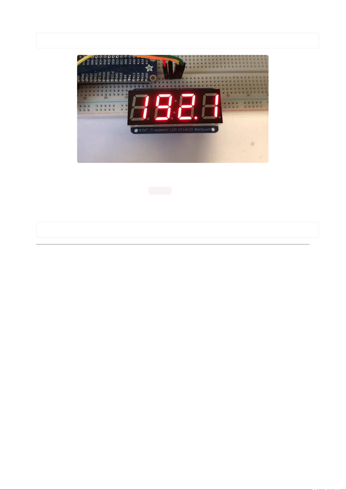
display.marquee('192.168.100.102... ')
By default it is 0.25 seconds, but you can change this by providing a second
parameter. You can optionally pass False for a third parameter if you would not like
to have it loop. So if you wanted each character to display for half a second and didn't
want it to loop, you would use the following:
display.marquee('192.168.100.102... ', 0.5, False)
1.2" 7-segment Backpack
These backpacks drive the massive 1.2" 7-segment modules. With 2 leds per segment
these make a gorgeous and impressive display. The 7-segment displays normally
require 16 pins to drive. This backpack uses an I2C constant-current matrix controller
on the back of the PCB, so you only need 2 pins to drive it!
The controller chip takes care of multiplexing all the LEDs in the background. All you
have to do is write data to it using the 2-pin I2C interface. There are three address
select pins so you can select one of 8 addresses to control up to 8 of these on a
single 2-pin I2C bus (as well as whatever other I2C chips or sensors you like). The
driver chip can 'dim' the entire display from 1/16 brightness up to full brightness in
1/16th steps. It cannot dim individual LEDs, only the entire display at once.
©Adafruit Industries Page 98 of 161
Page 99
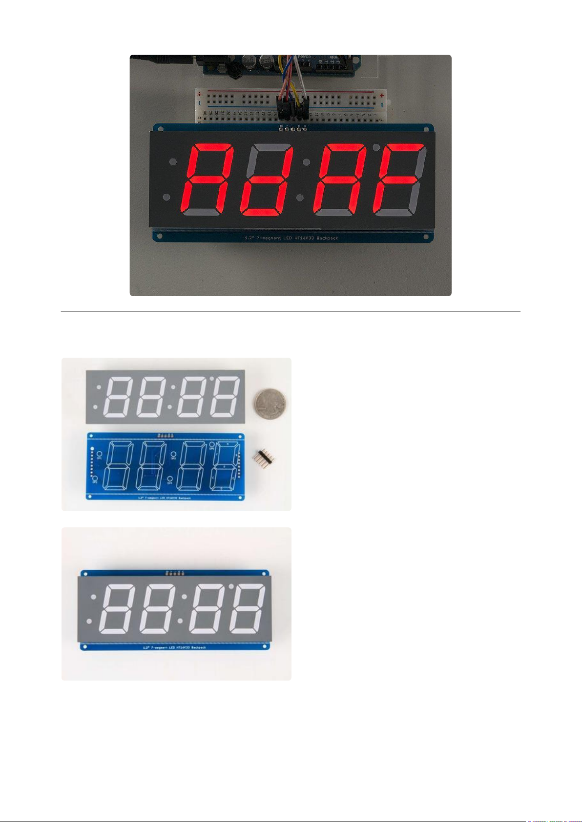
Assembly
When you buy a pack from Adafruit, it
comes with the fully tested and assembled
backpack as well as a 7-segment display in
one of the colors we provide (say, red,
yellow, blue or green). You'll need to
solder the matrix onto the backpack but its
an easy task.
Remove the parts from packaging and
place the LED matrix OVER the silkscreen
side. DO NOT PUT THE DISPLAY ON
UPSIDE DOWN OR IT WONT WORK!!
Check the image below to make sure the
'decimal point' dots are in the same
location as the ones on the silkscreen.
©Adafruit Industries Page 99 of 161
Page 100
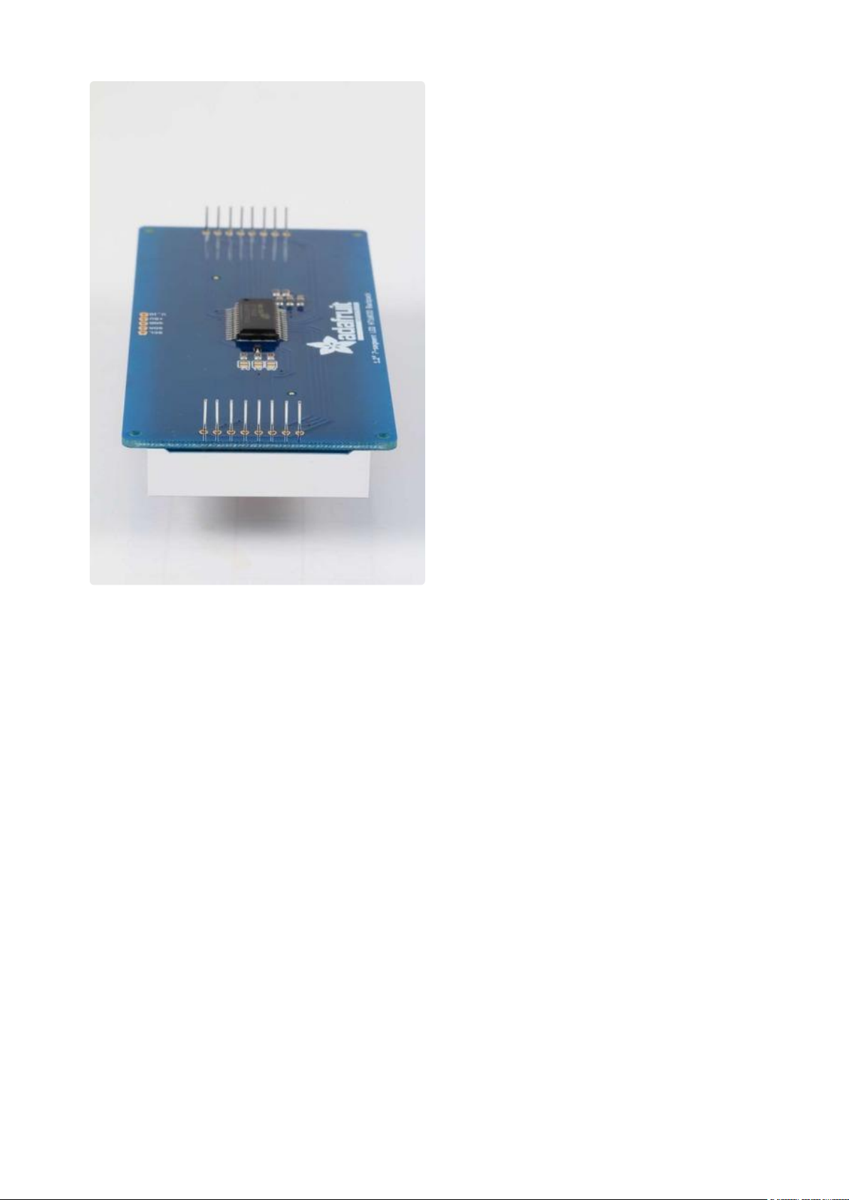
Turn the backpack over so its sitting flat on
the matrix and ready to solder.
©Adafruit Industries Page 100 of 161
 Loading...