

Page 1
Page 2

Pico C/C++ SDK
Colophon
Copyright © 2020 Raspberry Pi (Trading) Ltd.
The documentation of the RP2040 microcontroller is licensed under a Creative Commons Attribution-NoDerivatives 4.0
International (CC BY-ND).
build-date: 2021-01-21
build-version: fcd04ef-clean
Legal Disclaimer Notice
TECHNICAL AND RELIABILITY DATA FOR RASPBERRY PI PRODUCTS (INCLUDING DATASHEETS) AS MODIFIED FROM
TIME TO TIME (“RESOURCES”) ARE PROVIDED BY RASPBERRY PI (TRADING) LTD (“RPTL) "AS IS" AND ANY EXPRESS OR
IMPLIED WARRANTIES, INCLUDING, BUT NOT LIMITED TO, THE IMPLIED WARRANTIES OF MERCHANTABILITY AND
FITNESS FOR A PARTICULAR PURPOSE ARE DISCLAIMED. TO THE MAXIMUM EXTENT PERMITTED BY APPLICABLE
LAW IN NO EVENT SHALL RPTL BE LIABLE FOR ANY DIRECT, INDIRECT, INCIDENTAL, SPECIAL, EXEMPLARY, OR
CONSEQUENTIAL DAMAGES (INCLUDING, BUT NOT LIMITED TO, PROCUREMENT OF SUBSTITUTE GOODS OR
SERVICES; LOSS OF USE, DATA, OR PROFITS; OR BUSINESS INTERRUPTION) HOWEVER CAUSED AND ON ANY THEORY
OF LIABILITY, WHETHER IN CONTRACT, STRICT LIABILITY, OR TORT (INCLUDING NEGLIGENCE OR OTHERWISE)
ARISING IN ANY WAY OUT OF THE USE OF THE RESOURCES, EVEN IF ADVISED OF THE POSSIBILITY OF SUCH
DAMAGE.
RPTL reserves the right to make any enhancements, improvements, corrections or any other modifications to the
RESOURCES or any products described in them at any time and without further notice.
The RESOURCES are intended for skilled users with suitable levels of design knowledge. Users are solely responsible for
their selection and use of the RESOURCES and any application of the products described in them. User agrees to
indemnify and hold RPTL harmless against all liabilities, costs, damages or other losses arising out of their use of the
RESOURCES.
RPTL grants users permission to use the RESOURCES solely in conjunction with the Raspberry Pi products. All other use
of the RESOURCES is prohibited. No licence is granted to any other RPTL or other third party intellectual property right.
HIGH RISK ACTIVITIES. Raspberry Pi products are not designed, manufactured or intended for use in hazardous
environments requiring fail safe performance, such as in the operation of nuclear facilities, aircraft navigation or
communication systems, air traffic control, weapons systems or safety-critical applications (including life support
systems and other medical devices), in which the failure of the products could lead directly to death, personal injury or
severe physical or environmental damage (“High Risk Activities”). RPTL specifically disclaims any express or implied
warranty of fitness for High Risk Activities and accepts no liability for use or inclusions of Raspberry Pi products in High
Risk Activities.
Raspberry Pi products are provided subject to RPTL’s Standard Terms. RPTL’s provision of the RESOURCES does not
expand or otherwise modify RPTL’s Standard Terms including but not limited to the disclaimers and warranties expressed
in them.
Legal Disclaimer Notice 1
Page 3

Pico C/C++ SDK
Table of Contents
Colophon. . . . . . . . . . . . . . . . . . . . . . . . . . . . . . . . . . . . . . . . . . . . . . . . . . . . . . . . . . . . . . . . . . . . . . . . . . . . . . . . . . . . . . . . . . . . . . . . . . . . Ê1
Legal Disclaimer Notice . . . . . . . . . . . . . . . . . . . . . . . . . . . . . . . . . . . . . . . . . . . . . . . . . . . . . . . . . . . . . . . . . . . . . . . . . . . . . . . . . . . . Ê1
1. About the Pico SDK. . . . . . . . . . . . . . . . . . . . . . . . . . . . . . . . . . . . . . . . . . . . . . . . . . . . . . . . . . . . . . . . . . . . . . . . . . . . . . . . . . . . . . . . . Ê5
1.1. Introduction. . . . . . . . . . . . . . . . . . . . . . . . . . . . . . . . . . . . . . . . . . . . . . . . . . . . . . . . . . . . . . . . . . . . . . . . . . . . . . . . . . . . . . . . . . . Ê5
1.2. Anatomy of a Pico SDK Application . . . . . . . . . . . . . . . . . . . . . . . . . . . . . . . . . . . . . . . . . . . . . . . . . . . . . . . . . . . . . . . . . . . . . . Ê5
2. Pico SDK Architecture . . . . . . . . . . . . . . . . . . . . . . . . . . . . . . . . . . . . . . . . . . . . . . . . . . . . . . . . . . . . . . . . . . . . . . . . . . . . . . . . . . . . . . Ê8
2.1. The Build System. . . . . . . . . . . . . . . . . . . . . . . . . . . . . . . . . . . . . . . . . . . . . . . . . . . . . . . . . . . . . . . . . . . . . . . . . . . . . . . . . . . . . . Ê8
2.2. Every Library is an INTERFACE . . . . . . . . . . . . . . . . . . . . . . . . . . . . . . . . . . . . . . . . . . . . . . . . . . . . . . . . . . . . . . . . . . . . . . . . . . Ê9
2.3. Pico SDK Library Structure . . . . . . . . . . . . . . . . . . . . . . . . . . . . . . . . . . . . . . . . . . . . . . . . . . . . . . . . . . . . . . . . . . . . . . . . . . . . Ê10
2.3.1. Higher-level Libraries. . . . . . . . . . . . . . . . . . . . . . . . . . . . . . . . . . . . . . . . . . . . . . . . . . . . . . . . . . . . . . . . . . . . . . . . . . . . . Ê10
2.3.2. Runtime Support (pico_runtime, pico_standard_link) . . . . . . . . . . . . . . . . . . . . . . . . . . . . . . . . . . . . . . . . . . . . . . . . . Ê10
2.3.3. Hardware Support Libraries. . . . . . . . . . . . . . . . . . . . . . . . . . . . . . . . . . . . . . . . . . . . . . . . . . . . . . . . . . . . . . . . . . . . . . . Ê11
2.3.4. Hardware Structs Library . . . . . . . . . . . . . . . . . . . . . . . . . . . . . . . . . . . . . . . . . . . . . . . . . . . . . . . . . . . . . . . . . . . . . . . . . Ê12
2.3.5. Hardware Registers Library . . . . . . . . . . . . . . . . . . . . . . . . . . . . . . . . . . . . . . . . . . . . . . . . . . . . . . . . . . . . . . . . . . . . . . . Ê13
2.3.6. TinyUSB Port. . . . . . . . . . . . . . . . . . . . . . . . . . . . . . . . . . . . . . . . . . . . . . . . . . . . . . . . . . . . . . . . . . . . . . . . . . . . . . . . . . . . Ê14
2.4. Directory Structure . . . . . . . . . . . . . . . . . . . . . . . . . . . . . . . . . . . . . . . . . . . . . . . . . . . . . . . . . . . . . . . . . . . . . . . . . . . . . . . . . . . Ê14
2.4.1. Locations of Files. . . . . . . . . . . . . . . . . . . . . . . . . . . . . . . . . . . . . . . . . . . . . . . . . . . . . . . . . . . . . . . . . . . . . . . . . . . . . . . . Ê15
2.5. Conventions for Library Functions. . . . . . . . . . . . . . . . . . . . . . . . . . . . . . . . . . . . . . . . . . . . . . . . . . . . . . . . . . . . . . . . . . . . . . Ê16
2.5.1. Function Naming Conventions . . . . . . . . . . . . . . . . . . . . . . . . . . . . . . . . . . . . . . . . . . . . . . . . . . . . . . . . . . . . . . . . . . . . Ê16
2.5.2. Return Codes and Error Handling . . . . . . . . . . . . . . . . . . . . . . . . . . . . . . . . . . . . . . . . . . . . . . . . . . . . . . . . . . . . . . . . . . Ê17
2.5.3. Use of Inline Functions . . . . . . . . . . . . . . . . . . . . . . . . . . . . . . . . . . . . . . . . . . . . . . . . . . . . . . . . . . . . . . . . . . . . . . . . . . . Ê17
2.5.4. Builder Pattern for Hardware Configuration APIs . . . . . . . . . . . . . . . . . . . . . . . . . . . . . . . . . . . . . . . . . . . . . . . . . . . . Ê18
2.6. Customisation and Configuration Using Preprocessor variables . . . . . . . . . . . . . . . . . . . . . . . . . . . . . . . . . . . . . . . . . . . Ê19
2.6.1. Preprocessor Variables via Board Configuration File . . . . . . . . . . . . . . . . . . . . . . . . . . . . . . . . . . . . . . . . . . . . . . . . . Ê19
2.6.2. Preprocessor Variables Per Binary or Library via CMake . . . . . . . . . . . . . . . . . . . . . . . . . . . . . . . . . . . . . . . . . . . . . . Ê19
2.7. Pico SDK Runtime . . . . . . . . . . . . . . . . . . . . . . . . . . . . . . . . . . . . . . . . . . . . . . . . . . . . . . . . . . . . . . . . . . . . . . . . . . . . . . . . . . . . Ê20
2.7.1. Standard Input/Output (stdio) Support . . . . . . . . . . . . . . . . . . . . . . . . . . . . . . . . . . . . . . . . . . . . . . . . . . . . . . . . . . . . . Ê20
2.7.2. Floating-point support. . . . . . . . . . . . . . . . . . . . . . . . . . . . . . . . . . . . . . . . . . . . . . . . . . . . . . . . . . . . . . . . . . . . . . . . . . . . Ê21
2.7.3. Hardware Divider . . . . . . . . . . . . . . . . . . . . . . . . . . . . . . . . . . . . . . . . . . . . . . . . . . . . . . . . . . . . . . . . . . . . . . . . . . . . . . . . Ê24
2.8. Multi-core support. . . . . . . . . . . . . . . . . . . . . . . . . . . . . . . . . . . . . . . . . . . . . . . . . . . . . . . . . . . . . . . . . . . . . . . . . . . . . . . . . . . . Ê25
2.9. Using C++ . . . . . . . . . . . . . . . . . . . . . . . . . . . . . . . . . . . . . . . . . . . . . . . . . . . . . . . . . . . . . . . . . . . . . . . . . . . . . . . . . . . . . . . . . . . Ê26
2.10. Next Steps . . . . . . . . . . . . . . . . . . . . . . . . . . . . . . . . . . . . . . . . . . . . . . . . . . . . . . . . . . . . . . . . . . . . . . . . . . . . . . . . . . . . . . . . . Ê26
3. Using Programmable I/O (PIO). . . . . . . . . . . . . . . . . . . . . . . . . . . . . . . . . . . . . . . . . . . . . . . . . . . . . . . . . . . . . . . . . . . . . . . . . . . . . . Ê27
3.1. What is Programmable I/O (PIO)? . . . . . . . . . . . . . . . . . . . . . . . . . . . . . . . . . . . . . . . . . . . . . . . . . . . . . . . . . . . . . . . . . . . . . . Ê27
3.1.1. Background. . . . . . . . . . . . . . . . . . . . . . . . . . . . . . . . . . . . . . . . . . . . . . . . . . . . . . . . . . . . . . . . . . . . . . . . . . . . . . . . . . . . . Ê27
3.1.2. I/O Using dedicated hardware on your PC . . . . . . . . . . . . . . . . . . . . . . . . . . . . . . . . . . . . . . . . . . . . . . . . . . . . . . . . . . Ê27
3.1.3. I/O Using dedicated hardware on your Raspberry Pi or microcontroller. . . . . . . . . . . . . . . . . . . . . . . . . . . . . . . . . Ê27
3.1.4. I/O Using software control of GPIOs ("bit-banging") . . . . . . . . . . . . . . . . . . . . . . . . . . . . . . . . . . . . . . . . . . . . . . . . . . Ê28
3.1.5. Programmable I/O Hardware using FPGAs and CPLDs. . . . . . . . . . . . . . . . . . . . . . . . . . . . . . . . . . . . . . . . . . . . . . . Ê29
3.1.6. Programmable I/O Hardware using PIO . . . . . . . . . . . . . . . . . . . . . . . . . . . . . . . . . . . . . . . . . . . . . . . . . . . . . . . . . . . . Ê29
3.2. Getting started with PIO . . . . . . . . . . . . . . . . . . . . . . . . . . . . . . . . . . . . . . . . . . . . . . . . . . . . . . . . . . . . . . . . . . . . . . . . . . . . . . . Ê30
3.2.1. A First PIO Application . . . . . . . . . . . . . . . . . . . . . . . . . . . . . . . . . . . . . . . . . . . . . . . . . . . . . . . . . . . . . . . . . . . . . . . . . . . Ê30
3.2.2. A Real Example: WS2812 LEDs. . . . . . . . . . . . . . . . . . . . . . . . . . . . . . . . . . . . . . . . . . . . . . . . . . . . . . . . . . . . . . . . . . . . Ê34
3.2.3. PIO and DMA (A Logic Analyser). . . . . . . . . . . . . . . . . . . . . . . . . . . . . . . . . . . . . . . . . . . . . . . . . . . . . . . . . . . . . . . . . . . Ê41
3.2.4. Further examples . . . . . . . . . . . . . . . . . . . . . . . . . . . . . . . . . . . . . . . . . . . . . . . . . . . . . . . . . . . . . . . . . . . . . . . . . . . . . . . . Ê46
3.3. Using PIOASM, the PIO Assembler . . . . . . . . . . . . . . . . . . . . . . . . . . . . . . . . . . . . . . . . . . . . . . . . . . . . . . . . . . . . . . . . . . . . . Ê46
3.3.1. Usage . . . . . . . . . . . . . . . . . . . . . . . . . . . . . . . . . . . . . . . . . . . . . . . . . . . . . . . . . . . . . . . . . . . . . . . . . . . . . . . . . . . . . . . . . . Ê46
3.3.2. Directives. . . . . . . . . . . . . . . . . . . . . . . . . . . . . . . . . . . . . . . . . . . . . . . . . . . . . . . . . . . . . . . . . . . . . . . . . . . . . . . . . . . . . . . Ê47
3.3.3. Values. . . . . . . . . . . . . . . . . . . . . . . . . . . . . . . . . . . . . . . . . . . . . . . . . . . . . . . . . . . . . . . . . . . . . . . . . . . . . . . . . . . . . . . . . . Ê48
3.3.4. Expressions. . . . . . . . . . . . . . . . . . . . . . . . . . . . . . . . . . . . . . . . . . . . . . . . . . . . . . . . . . . . . . . . . . . . . . . . . . . . . . . . . . . . . Ê48
3.3.5. Comments. . . . . . . . . . . . . . . . . . . . . . . . . . . . . . . . . . . . . . . . . . . . . . . . . . . . . . . . . . . . . . . . . . . . . . . . . . . . . . . . . . . . . . Ê48
3.3.6. Labels. . . . . . . . . . . . . . . . . . . . . . . . . . . . . . . . . . . . . . . . . . . . . . . . . . . . . . . . . . . . . . . . . . . . . . . . . . . . . . . . . . . . . . . . . . Ê48
3.3.7. Instructions . . . . . . . . . . . . . . . . . . . . . . . . . . . . . . . . . . . . . . . . . . . . . . . . . . . . . . . . . . . . . . . . . . . . . . . . . . . . . . . . . . . . . Ê49
3.3.8. Output pass through . . . . . . . . . . . . . . . . . . . . . . . . . . . . . . . . . . . . . . . . . . . . . . . . . . . . . . . . . . . . . . . . . . . . . . . . . . . . . Ê49
3.3.9. Language generators . . . . . . . . . . . . . . . . . . . . . . . . . . . . . . . . . . . . . . . . . . . . . . . . . . . . . . . . . . . . . . . . . . . . . . . . . . . . Ê50
Table of Contents 2
Page 4

Pico C/C++ SDK
3.4. PIO Instruction Set Reference. . . . . . . . . . . . . . . . . . . . . . . . . . . . . . . . . . . . . . . . . . . . . . . . . . . . . . . . . . . . . . . . . . . . . . . . . . Ê55
3.4.1. Summary . . . . . . . . . . . . . . . . . . . . . . . . . . . . . . . . . . . . . . . . . . . . . . . . . . . . . . . . . . . . . . . . . . . . . . . . . . . . . . . . . . . . . . . Ê55
3.4.2. JMP . . . . . . . . . . . . . . . . . . . . . . . . . . . . . . . . . . . . . . . . . . . . . . . . . . . . . . . . . . . . . . . . . . . . . . . . . . . . . . . . . . . . . . . . . . . Ê56
3.4.3. WAIT. . . . . . . . . . . . . . . . . . . . . . . . . . . . . . . . . . . . . . . . . . . . . . . . . . . . . . . . . . . . . . . . . . . . . . . . . . . . . . . . . . . . . . . . . . . Ê57
3.4.4. IN. . . . . . . . . . . . . . . . . . . . . . . . . . . . . . . . . . . . . . . . . . . . . . . . . . . . . . . . . . . . . . . . . . . . . . . . . . . . . . . . . . . . . . . . . . . . . . Ê58
3.4.5. OUT. . . . . . . . . . . . . . . . . . . . . . . . . . . . . . . . . . . . . . . . . . . . . . . . . . . . . . . . . . . . . . . . . . . . . . . . . . . . . . . . . . . . . . . . . . . . Ê59
3.4.6. PUSH . . . . . . . . . . . . . . . . . . . . . . . . . . . . . . . . . . . . . . . . . . . . . . . . . . . . . . . . . . . . . . . . . . . . . . . . . . . . . . . . . . . . . . . . . . Ê60
3.4.7. PULL . . . . . . . . . . . . . . . . . . . . . . . . . . . . . . . . . . . . . . . . . . . . . . . . . . . . . . . . . . . . . . . . . . . . . . . . . . . . . . . . . . . . . . . . . . . Ê61
3.4.8. MOV . . . . . . . . . . . . . . . . . . . . . . . . . . . . . . . . . . . . . . . . . . . . . . . . . . . . . . . . . . . . . . . . . . . . . . . . . . . . . . . . . . . . . . . . . . . Ê61
3.4.9. IRQ . . . . . . . . . . . . . . . . . . . . . . . . . . . . . . . . . . . . . . . . . . . . . . . . . . . . . . . . . . . . . . . . . . . . . . . . . . . . . . . . . . . . . . . . . . . . Ê63
3.4.10. SET . . . . . . . . . . . . . . . . . . . . . . . . . . . . . . . . . . . . . . . . . . . . . . . . . . . . . . . . . . . . . . . . . . . . . . . . . . . . . . . . . . . . . . . . . . . Ê64
4. Library Documentation . . . . . . . . . . . . . . . . . . . . . . . . . . . . . . . . . . . . . . . . . . . . . . . . . . . . . . . . . . . . . . . . . . . . . . . . . . . . . . . . . . . . Ê65
4.1. Hardware APIs . . . . . . . . . . . . . . . . . . . . . . . . . . . . . . . . . . . . . . . . . . . . . . . . . . . . . . . . . . . . . . . . . . . . . . . . . . . . . . . . . . . . . . . Ê65
4.1.1. hardware_adc . . . . . . . . . . . . . . . . . . . . . . . . . . . . . . . . . . . . . . . . . . . . . . . . . . . . . . . . . . . . . . . . . . . . . . . . . . . . . . . . . . . Ê65
4.1.2. hardware_base . . . . . . . . . . . . . . . . . . . . . . . . . . . . . . . . . . . . . . . . . . . . . . . . . . . . . . . . . . . . . . . . . . . . . . . . . . . . . . . . . . Ê70
4.1.3. hardware_claim . . . . . . . . . . . . . . . . . . . . . . . . . . . . . . . . . . . . . . . . . . . . . . . . . . . . . . . . . . . . . . . . . . . . . . . . . . . . . . . . . Ê71
4.1.4. hardware_clocks . . . . . . . . . . . . . . . . . . . . . . . . . . . . . . . . . . . . . . . . . . . . . . . . . . . . . . . . . . . . . . . . . . . . . . . . . . . . . . . . Ê73
4.1.5. hardware_divider . . . . . . . . . . . . . . . . . . . . . . . . . . . . . . . . . . . . . . . . . . . . . . . . . . . . . . . . . . . . . . . . . . . . . . . . . . . . . . . . Ê79
4.1.6. hardware_dma . . . . . . . . . . . . . . . . . . . . . . . . . . . . . . . . . . . . . . . . . . . . . . . . . . . . . . . . . . . . . . . . . . . . . . . . . . . . . . . . . . Ê87
4.1.7. channel_config . . . . . . . . . . . . . . . . . . . . . . . . . . . . . . . . . . . . . . . . . . . . . . . . . . . . . . . . . . . . . . . . . . . . . . . . . . . . . . . . . . Ê94
4.1.8. hardware_flash. . . . . . . . . . . . . . . . . . . . . . . . . . . . . . . . . . . . . . . . . . . . . . . . . . . . . . . . . . . . . . . . . . . . . . . . . . . . . . . . . . Ê98
4.1.9. hardware_gpio . . . . . . . . . . . . . . . . . . . . . . . . . . . . . . . . . . . . . . . . . . . . . . . . . . . . . . . . . . . . . . . . . . . . . . . . . . . . . . . . . Ê100
4.1.10. hardware_i2c . . . . . . . . . . . . . . . . . . . . . . . . . . . . . . . . . . . . . . . . . . . . . . . . . . . . . . . . . . . . . . . . . . . . . . . . . . . . . . . . . Ê109
4.1.11. hardware_interp. . . . . . . . . . . . . . . . . . . . . . . . . . . . . . . . . . . . . . . . . . . . . . . . . . . . . . . . . . . . . . . . . . . . . . . . . . . . . . . Ê116
4.1.12. interp_config. . . . . . . . . . . . . . . . . . . . . . . . . . . . . . . . . . . . . . . . . . . . . . . . . . . . . . . . . . . . . . . . . . . . . . . . . . . . . . . . . . Ê121
4.1.13. hardware_irq. . . . . . . . . . . . . . . . . . . . . . . . . . . . . . . . . . . . . . . . . . . . . . . . . . . . . . . . . . . . . . . . . . . . . . . . . . . . . . . . . . Ê124
4.1.14. hardware_pio . . . . . . . . . . . . . . . . . . . . . . . . . . . . . . . . . . . . . . . . . . . . . . . . . . . . . . . . . . . . . . . . . . . . . . . . . . . . . . . . . Ê129
4.1.15. sm_config . . . . . . . . . . . . . . . . . . . . . . . . . . . . . . . . . . . . . . . . . . . . . . . . . . . . . . . . . . . . . . . . . . . . . . . . . . . . . . . . . . . . Ê143
4.1.16. hardware_pll . . . . . . . . . . . . . . . . . . . . . . . . . . . . . . . . . . . . . . . . . . . . . . . . . . . . . . . . . . . . . . . . . . . . . . . . . . . . . . . . . . Ê149
4.1.17. hardware_pwm . . . . . . . . . . . . . . . . . . . . . . . . . . . . . . . . . . . . . . . . . . . . . . . . . . . . . . . . . . . . . . . . . . . . . . . . . . . . . . . Ê150
4.1.18. hardware_resets . . . . . . . . . . . . . . . . . . . . . . . . . . . . . . . . . . . . . . . . . . . . . . . . . . . . . . . . . . . . . . . . . . . . . . . . . . . . . . Ê159
4.1.19. hardware_rtc . . . . . . . . . . . . . . . . . . . . . . . . . . . . . . . . . . . . . . . . . . . . . . . . . . . . . . . . . . . . . . . . . . . . . . . . . . . . . . . . . Ê161
4.1.20. hardware_spi . . . . . . . . . . . . . . . . . . . . . . . . . . . . . . . . . . . . . . . . . . . . . . . . . . . . . . . . . . . . . . . . . . . . . . . . . . . . . . . . . Ê163
4.1.21. hardware_sync. . . . . . . . . . . . . . . . . . . . . . . . . . . . . . . . . . . . . . . . . . . . . . . . . . . . . . . . . . . . . . . . . . . . . . . . . . . . . . . . Ê168
4.1.22. hardware_timer . . . . . . . . . . . . . . . . . . . . . . . . . . . . . . . . . . . . . . . . . . . . . . . . . . . . . . . . . . . . . . . . . . . . . . . . . . . . . . . Ê173
4.1.23. hardware_uart . . . . . . . . . . . . . . . . . . . . . . . . . . . . . . . . . . . . . . . . . . . . . . . . . . . . . . . . . . . . . . . . . . . . . . . . . . . . . . . . Ê177
4.1.24. hardware_vreg . . . . . . . . . . . . . . . . . . . . . . . . . . . . . . . . . . . . . . . . . . . . . . . . . . . . . . . . . . . . . . . . . . . . . . . . . . . . . . . . Ê183
4.1.25. hardware_watchdog . . . . . . . . . . . . . . . . . . . . . . . . . . . . . . . . . . . . . . . . . . . . . . . . . . . . . . . . . . . . . . . . . . . . . . . . . . . Ê183
4.1.26. hardware_xosc. . . . . . . . . . . . . . . . . . . . . . . . . . . . . . . . . . . . . . . . . . . . . . . . . . . . . . . . . . . . . . . . . . . . . . . . . . . . . . . . Ê185
4.2. High Level APIs . . . . . . . . . . . . . . . . . . . . . . . . . . . . . . . . . . . . . . . . . . . . . . . . . . . . . . . . . . . . . . . . . . . . . . . . . . . . . . . . . . . . . Ê186
4.2.1. pico_multicore . . . . . . . . . . . . . . . . . . . . . . . . . . . . . . . . . . . . . . . . . . . . . . . . . . . . . . . . . . . . . . . . . . . . . . . . . . . . . . . . . Ê187
4.2.2. fifo . . . . . . . . . . . . . . . . . . . . . . . . . . . . . . . . . . . . . . . . . . . . . . . . . . . . . . . . . . . . . . . . . . . . . . . . . . . . . . . . . . . . . . . . . . . Ê189
4.2.3. pico_stdlib . . . . . . . . . . . . . . . . . . . . . . . . . . . . . . . . . . . . . . . . . . . . . . . . . . . . . . . . . . . . . . . . . . . . . . . . . . . . . . . . . . . . . Ê190
4.2.4. pico_sync . . . . . . . . . . . . . . . . . . . . . . . . . . . . . . . . . . . . . . . . . . . . . . . . . . . . . . . . . . . . . . . . . . . . . . . . . . . . . . . . . . . . . Ê192
4.2.5. critical_section . . . . . . . . . . . . . . . . . . . . . . . . . . . . . . . . . . . . . . . . . . . . . . . . . . . . . . . . . . . . . . . . . . . . . . . . . . . . . . . . . Ê192
4.2.6. mutex. . . . . . . . . . . . . . . . . . . . . . . . . . . . . . . . . . . . . . . . . . . . . . . . . . . . . . . . . . . . . . . . . . . . . . . . . . . . . . . . . . . . . . . . . Ê194
4.2.7. sem. . . . . . . . . . . . . . . . . . . . . . . . . . . . . . . . . . . . . . . . . . . . . . . . . . . . . . . . . . . . . . . . . . . . . . . . . . . . . . . . . . . . . . . . . . . Ê196
4.2.8. pico_time. . . . . . . . . . . . . . . . . . . . . . . . . . . . . . . . . . . . . . . . . . . . . . . . . . . . . . . . . . . . . . . . . . . . . . . . . . . . . . . . . . . . . . Ê198
4.2.9. timestamp. . . . . . . . . . . . . . . . . . . . . . . . . . . . . . . . . . . . . . . . . . . . . . . . . . . . . . . . . . . . . . . . . . . . . . . . . . . . . . . . . . . . . Ê198
4.2.10. sleep. . . . . . . . . . . . . . . . . . . . . . . . . . . . . . . . . . . . . . . . . . . . . . . . . . . . . . . . . . . . . . . . . . . . . . . . . . . . . . . . . . . . . . . . . Ê201
4.2.11. alarm . . . . . . . . . . . . . . . . . . . . . . . . . . . . . . . . . . . . . . . . . . . . . . . . . . . . . . . . . . . . . . . . . . . . . . . . . . . . . . . . . . . . . . . . Ê202
4.2.12. repeating_timer . . . . . . . . . . . . . . . . . . . . . . . . . . . . . . . . . . . . . . . . . . . . . . . . . . . . . . . . . . . . . . . . . . . . . . . . . . . . . . . Ê208
4.2.13. pico_util . . . . . . . . . . . . . . . . . . . . . . . . . . . . . . . . . . . . . . . . . . . . . . . . . . . . . . . . . . . . . . . . . . . . . . . . . . . . . . . . . . . . . . Ê211
4.2.14. datetime . . . . . . . . . . . . . . . . . . . . . . . . . . . . . . . . . . . . . . . . . . . . . . . . . . . . . . . . . . . . . . . . . . . . . . . . . . . . . . . . . . . . . Ê211
4.2.15. pheap. . . . . . . . . . . . . . . . . . . . . . . . . . . . . . . . . . . . . . . . . . . . . . . . . . . . . . . . . . . . . . . . . . . . . . . . . . . . . . . . . . . . . . . . Ê212
4.2.16. queue. . . . . . . . . . . . . . . . . . . . . . . . . . . . . . . . . . . . . . . . . . . . . . . . . . . . . . . . . . . . . . . . . . . . . . . . . . . . . . . . . . . . . . . . Ê212
4.3. Third-party Libraries . . . . . . . . . . . . . . . . . . . . . . . . . . . . . . . . . . . . . . . . . . . . . . . . . . . . . . . . . . . . . . . . . . . . . . . . . . . . . . . . . Ê216
4.3.1. tinyusb_device . . . . . . . . . . . . . . . . . . . . . . . . . . . . . . . . . . . . . . . . . . . . . . . . . . . . . . . . . . . . . . . . . . . . . . . . . . . . . . . . . Ê216
4.3.2. tinyusb_host . . . . . . . . . . . . . . . . . . . . . . . . . . . . . . . . . . . . . . . . . . . . . . . . . . . . . . . . . . . . . . . . . . . . . . . . . . . . . . . . . . . Ê216
4.4. Runtime Infrastructure. . . . . . . . . . . . . . . . . . . . . . . . . . . . . . . . . . . . . . . . . . . . . . . . . . . . . . . . . . . . . . . . . . . . . . . . . . . . . . . Ê216
Table of Contents 3
Page 5

Pico C/C++ SDK
4.4.1. boot_stage2 . . . . . . . . . . . . . . . . . . . . . . . . . . . . . . . . . . . . . . . . . . . . . . . . . . . . . . . . . . . . . . . . . . . . . . . . . . . . . . . . . . . Ê217
4.4.2. pico_base . . . . . . . . . . . . . . . . . . . . . . . . . . . . . . . . . . . . . . . . . . . . . . . . . . . . . . . . . . . . . . . . . . . . . . . . . . . . . . . . . . . . . Ê217
4.4.3. pico_bit_ops . . . . . . . . . . . . . . . . . . . . . . . . . . . . . . . . . . . . . . . . . . . . . . . . . . . . . . . . . . . . . . . . . . . . . . . . . . . . . . . . . . . Ê217
4.4.4. pico_bootrom . . . . . . . . . . . . . . . . . . . . . . . . . . . . . . . . . . . . . . . . . . . . . . . . . . . . . . . . . . . . . . . . . . . . . . . . . . . . . . . . . . Ê218
4.4.5. pico_cxx_options . . . . . . . . . . . . . . . . . . . . . . . . . . . . . . . . . . . . . . . . . . . . . . . . . . . . . . . . . . . . . . . . . . . . . . . . . . . . . . . Ê219
4.4.6. pico_divider. . . . . . . . . . . . . . . . . . . . . . . . . . . . . . . . . . . . . . . . . . . . . . . . . . . . . . . . . . . . . . . . . . . . . . . . . . . . . . . . . . . . Ê219
4.4.7. pico_double. . . . . . . . . . . . . . . . . . . . . . . . . . . . . . . . . . . . . . . . . . . . . . . . . . . . . . . . . . . . . . . . . . . . . . . . . . . . . . . . . . . . Ê227
4.4.8. pico_float. . . . . . . . . . . . . . . . . . . . . . . . . . . . . . . . . . . . . . . . . . . . . . . . . . . . . . . . . . . . . . . . . . . . . . . . . . . . . . . . . . . . . . Ê227
4.4.9. pico_int64_ops . . . . . . . . . . . . . . . . . . . . . . . . . . . . . . . . . . . . . . . . . . . . . . . . . . . . . . . . . . . . . . . . . . . . . . . . . . . . . . . . . Ê228
4.4.10. pico_malloc . . . . . . . . . . . . . . . . . . . . . . . . . . . . . . . . . . . . . . . . . . . . . . . . . . . . . . . . . . . . . . . . . . . . . . . . . . . . . . . . . . Ê228
4.4.11. pico_mem_ops. . . . . . . . . . . . . . . . . . . . . . . . . . . . . . . . . . . . . . . . . . . . . . . . . . . . . . . . . . . . . . . . . . . . . . . . . . . . . . . . Ê228
4.4.12. pico_platform . . . . . . . . . . . . . . . . . . . . . . . . . . . . . . . . . . . . . . . . . . . . . . . . . . . . . . . . . . . . . . . . . . . . . . . . . . . . . . . . . Ê228
4.4.13. pico_printf . . . . . . . . . . . . . . . . . . . . . . . . . . . . . . . . . . . . . . . . . . . . . . . . . . . . . . . . . . . . . . . . . . . . . . . . . . . . . . . . . . . . Ê228
4.4.14. pico_runtime. . . . . . . . . . . . . . . . . . . . . . . . . . . . . . . . . . . . . . . . . . . . . . . . . . . . . . . . . . . . . . . . . . . . . . . . . . . . . . . . . . Ê228
4.4.15. pico_stdio . . . . . . . . . . . . . . . . . . . . . . . . . . . . . . . . . . . . . . . . . . . . . . . . . . . . . . . . . . . . . . . . . . . . . . . . . . . . . . . . . . . . Ê228
4.4.16. pico_stdio_semihosting . . . . . . . . . . . . . . . . . . . . . . . . . . . . . . . . . . . . . . . . . . . . . . . . . . . . . . . . . . . . . . . . . . . . . . . . Ê230
4.4.17. pico_stdio_uart. . . . . . . . . . . . . . . . . . . . . . . . . . . . . . . . . . . . . . . . . . . . . . . . . . . . . . . . . . . . . . . . . . . . . . . . . . . . . . . . Ê230
4.4.18. pico_stdio_usb . . . . . . . . . . . . . . . . . . . . . . . . . . . . . . . . . . . . . . . . . . . . . . . . . . . . . . . . . . . . . . . . . . . . . . . . . . . . . . . . Ê232
4.4.19. pico_standard_link. . . . . . . . . . . . . . . . . . . . . . . . . . . . . . . . . . . . . . . . . . . . . . . . . . . . . . . . . . . . . . . . . . . . . . . . . . . . . Ê232
4.5. External API Headers . . . . . . . . . . . . . . . . . . . . . . . . . . . . . . . . . . . . . . . . . . . . . . . . . . . . . . . . . . . . . . . . . . . . . . . . . . . . . . . . Ê232
4.5.1. boot_picoboot . . . . . . . . . . . . . . . . . . . . . . . . . . . . . . . . . . . . . . . . . . . . . . . . . . . . . . . . . . . . . . . . . . . . . . . . . . . . . . . . . Ê232
4.5.2. boot_uf2 . . . . . . . . . . . . . . . . . . . . . . . . . . . . . . . . . . . . . . . . . . . . . . . . . . . . . . . . . . . . . . . . . . . . . . . . . . . . . . . . . . . . . . Ê232
Appendix A: App Notes . . . . . . . . . . . . . . . . . . . . . . . . . . . . . . . . . . . . . . . . . . . . . . . . . . . . . . . . . . . . . . . . . . . . . . . . . . . . . . . . . . . . . Ê233
Attaching a 7 segment LED via GPIO . . . . . . . . . . . . . . . . . . . . . . . . . . . . . . . . . . . . . . . . . . . . . . . . . . . . . . . . . . . . . . . . . . . . . . Ê233
Wiring information . . . . . . . . . . . . . . . . . . . . . . . . . . . . . . . . . . . . . . . . . . . . . . . . . . . . . . . . . . . . . . . . . . . . . . . . . . . . . . . . . . . Ê233
List of Files. . . . . . . . . . . . . . . . . . . . . . . . . . . . . . . . . . . . . . . . . . . . . . . . . . . . . . . . . . . . . . . . . . . . . . . . . . . . . . . . . . . . . . . . . . Ê233
Bill of Materials . . . . . . . . . . . . . . . . . . . . . . . . . . . . . . . . . . . . . . . . . . . . . . . . . . . . . . . . . . . . . . . . . . . . . . . . . . . . . . . . . . . . . . Ê235
DHT-11, DHT-22, and AM2302 Sensors . . . . . . . . . . . . . . . . . . . . . . . . . . . . . . . . . . . . . . . . . . . . . . . . . . . . . . . . . . . . . . . . . . . . Ê236
Wiring information . . . . . . . . . . . . . . . . . . . . . . . . . . . . . . . . . . . . . . . . . . . . . . . . . . . . . . . . . . . . . . . . . . . . . . . . . . . . . . . . . . . Ê236
List of Files. . . . . . . . . . . . . . . . . . . . . . . . . . . . . . . . . . . . . . . . . . . . . . . . . . . . . . . . . . . . . . . . . . . . . . . . . . . . . . . . . . . . . . . . . . Ê237
Bill of Materials . . . . . . . . . . . . . . . . . . . . . . . . . . . . . . . . . . . . . . . . . . . . . . . . . . . . . . . . . . . . . . . . . . . . . . . . . . . . . . . . . . . . . . Ê239
Attaching a BME280 temperature/humidity/pressure sensor via SPI . . . . . . . . . . . . . . . . . . . . . . . . . . . . . . . . . . . . . . . . . . Ê239
Wiring information . . . . . . . . . . . . . . . . . . . . . . . . . . . . . . . . . . . . . . . . . . . . . . . . . . . . . . . . . . . . . . . . . . . . . . . . . . . . . . . . . . . Ê239
List of Files. . . . . . . . . . . . . . . . . . . . . . . . . . . . . . . . . . . . . . . . . . . . . . . . . . . . . . . . . . . . . . . . . . . . . . . . . . . . . . . . . . . . . . . . . . Ê240
Bill of Materials . . . . . . . . . . . . . . . . . . . . . . . . . . . . . . . . . . . . . . . . . . . . . . . . . . . . . . . . . . . . . . . . . . . . . . . . . . . . . . . . . . . . . . Ê244
Attaching a MPU9250 accelerometer/gyroscope via SPI. . . . . . . . . . . . . . . . . . . . . . . . . . . . . . . . . . . . . . . . . . . . . . . . . . . . . Ê244
Wiring information . . . . . . . . . . . . . . . . . . . . . . . . . . . . . . . . . . . . . . . . . . . . . . . . . . . . . . . . . . . . . . . . . . . . . . . . . . . . . . . . . . . Ê245
List of Files. . . . . . . . . . . . . . . . . . . . . . . . . . . . . . . . . . . . . . . . . . . . . . . . . . . . . . . . . . . . . . . . . . . . . . . . . . . . . . . . . . . . . . . . . . Ê245
Bill of Materials . . . . . . . . . . . . . . . . . . . . . . . . . . . . . . . . . . . . . . . . . . . . . . . . . . . . . . . . . . . . . . . . . . . . . . . . . . . . . . . . . . . . . . Ê248
Attaching a MPU6050 accelerometer/gyroscope via I2C. . . . . . . . . . . . . . . . . . . . . . . . . . . . . . . . . . . . . . . . . . . . . . . . . . . . . Ê248
Wiring information . . . . . . . . . . . . . . . . . . . . . . . . . . . . . . . . . . . . . . . . . . . . . . . . . . . . . . . . . . . . . . . . . . . . . . . . . . . . . . . . . . . Ê249
List of Files. . . . . . . . . . . . . . . . . . . . . . . . . . . . . . . . . . . . . . . . . . . . . . . . . . . . . . . . . . . . . . . . . . . . . . . . . . . . . . . . . . . . . . . . . . Ê249
Bill of Materials . . . . . . . . . . . . . . . . . . . . . . . . . . . . . . . . . . . . . . . . . . . . . . . . . . . . . . . . . . . . . . . . . . . . . . . . . . . . . . . . . . . . . . Ê251
Attaching a 16x2 LCD via I2C . . . . . . . . . . . . . . . . . . . . . . . . . . . . . . . . . . . . . . . . . . . . . . . . . . . . . . . . . . . . . . . . . . . . . . . . . . . . . Ê252
Wiring information . . . . . . . . . . . . . . . . . . . . . . . . . . . . . . . . . . . . . . . . . . . . . . . . . . . . . . . . . . . . . . . . . . . . . . . . . . . . . . . . . . . Ê252
List of Files. . . . . . . . . . . . . . . . . . . . . . . . . . . . . . . . . . . . . . . . . . . . . . . . . . . . . . . . . . . . . . . . . . . . . . . . . . . . . . . . . . . . . . . . . . Ê252
Bill of Materials . . . . . . . . . . . . . . . . . . . . . . . . . . . . . . . . . . . . . . . . . . . . . . . . . . . . . . . . . . . . . . . . . . . . . . . . . . . . . . . . . . . . . . Ê255
Appendix B: SDK Configuration . . . . . . . . . . . . . . . . . . . . . . . . . . . . . . . . . . . . . . . . . . . . . . . . . . . . . . . . . . . . . . . . . . . . . . . . . . . . . . Ê256
Configuration Parameters. . . . . . . . . . . . . . . . . . . . . . . . . . . . . . . . . . . . . . . . . . . . . . . . . . . . . . . . . . . . . . . . . . . . . . . . . . . . . . . . Ê256
Appendix C: CMake Build Configuration. . . . . . . . . . . . . . . . . . . . . . . . . . . . . . . . . . . . . . . . . . . . . . . . . . . . . . . . . . . . . . . . . . . . . . . Ê260
Configuration Parameters. . . . . . . . . . . . . . . . . . . . . . . . . . . . . . . . . . . . . . . . . . . . . . . . . . . . . . . . . . . . . . . . . . . . . . . . . . . . . . . . Ê260
Control of binary type produced (advanced). . . . . . . . . . . . . . . . . . . . . . . . . . . . . . . . . . . . . . . . . . . . . . . . . . . . . . . . . . . . . Ê261
Appendix D: Board Configuration. . . . . . . . . . . . . . . . . . . . . . . . . . . . . . . . . . . . . . . . . . . . . . . . . . . . . . . . . . . . . . . . . . . . . . . . . . . . . Ê262
Board Configuration . . . . . . . . . . . . . . . . . . . . . . . . . . . . . . . . . . . . . . . . . . . . . . . . . . . . . . . . . . . . . . . . . . . . . . . . . . . . . . . . . . . . . Ê262
The Configuration files . . . . . . . . . . . . . . . . . . . . . . . . . . . . . . . . . . . . . . . . . . . . . . . . . . . . . . . . . . . . . . . . . . . . . . . . . . . . . . . Ê262
Building applications with a custom board configuration . . . . . . . . . . . . . . . . . . . . . . . . . . . . . . . . . . . . . . . . . . . . . . . . . Ê263
Available configuration parameters . . . . . . . . . . . . . . . . . . . . . . . . . . . . . . . . . . . . . . . . . . . . . . . . . . . . . . . . . . . . . . . . . . . . Ê263
Appendix E: Building the Pico SDK API documentation. . . . . . . . . . . . . . . . . . . . . . . . . . . . . . . . . . . . . . . . . . . . . . . . . . . . . . . . . . Ê264
Table of Contents 4
Page 6

Pico C/C++ SDK
Chapter 1. About the Pico SDK
1.1. Introduction
The Pico SDK (Software Development Kit) provides the headers, libraries and build system necessary to write programs
for RP2040-based devices such as Raspberry Pi Pico in C, C++ or Arm assembly language.
The Pico SDK is designed to provide an API and programming environment that is familiar both to non-embedded C
developers and embedded C developers alike. A single program runs on the device at a time with a conventional main()
method. Standard C/C++ libraries are supported along with APIs for accessing RP2040’s hardware, including DMA, IRQs,
and the wide variety fixed function peripherals and PIO (Programmable IO).
Additionally the Pico SDK provides higher level libraries for dealing with timers, USB, synchronization and multi-core
programming, along with additional high level functionality built using PIO such as audio. These libraries should be
comprehensive enough that your application code rarely, if at all, needs to access hardware registers directly. However, if
you do need or prefer to access the raw hardware, you will also find complete and fully-commented register definition
headers in the SDK. There’s no need to look up addresses in the datasheet.
The Pico SDK can be used to build anything from simple applications, full fledged runtime environments such as
MicroPython, to low level software such as RP2040’s on-chip bootrom itself.
Looking to get started?
This book documents the Pico SDK APIs, explains the internals and overall design of the SDK, and
explores some deeper topics like using the PIO assembler to build new interfaces to external hardware.
For a quick start with setting up the SDK and writing Pico SDK programs, Getting started with Raspberry
Pi Pico is the best place to start.
1.2. Anatomy of a Pico SDK Application
Before going completely depth-first in our traversal of the SDK, it’s worth getting a little breadth by looking at one of the
SDK examples covered in Getting started with Raspberry Pi Pico, in more detail.
Pico Examples: https://github.com/raspberrypi/pico-examples/tree/master/blink/blink.c Lines 1 - 19
Ê1 /**
Ê2 * Copyright (c) 2020 Raspberry Pi (Trading) Ltd.
Ê3 *
Ê4 * SPDX-License-Identifier: BSD-3-Clause
Ê5 */
Ê6
Ê7 #include "pico/stdlib.h"
Ê8
Ê9 int main() {
10 const uint LED_PIN = 25;
11 gpio_init(LED_PIN);
12 gpio_set_dir(LED_PIN, GPIO_OUT);
13 while (true) {
14 gpio_put(LED_PIN, 1);
15 sleep_ms(250);
16 gpio_put(LED_PIN, 0);
17 sleep_ms(250);
18 }
1.1. Introduction 5
Page 7

Pico C/C++ SDK
19 }
This program consists only of a single C file, with a single function. As with almost any C programming environment, the
function called main() is special, and is the point where the language runtime first hands over control to your program,
after doing things like initialising static variables with their values. In the Pico SDK the main() function does not take any
arguments. It’s quite common for the main() function not to return, as is shown here.
NOTE
The return code of main() is ignored by the SDK runtime.
At the top of the C file, we include a header called pico/stdlib.h. This is an umbrella header that pulls in some other
commonly used headers. In particular, the ones needed here are hardware/gpio.h, which is used for accessing the general
purpose IOs on RP2040 (the gpio_xxx functions here), and pico/time.h which contains, among other things, the sleep_ms
function. Broadly speaking, a library whose name starts with pico provides high level APIs and concepts, or aggregates
smaller interfaces; a name beginning with hardware indicates a thinner abstraction between your code and RP2040 on-chip
hardware.
So, using mainly the hardware_gpio and pico_time libraries, this C program will blink an LED connected to GPIO25 on and
off, twice per second, forever (or at least until unplugged). In the directory containing the C file (you can click the link
above the source listing to go there), there is one other file which lives alongside it.
Directory listing of pico-examples/blink
blink
├── blink.c
└── CMakeLists.txt
0 directories, 2 files
The second file is a CMake file, which tells the Pico SDK how to turn the C file into a binary application for an RP2040based microcontroller board. Later sections will detail exactly what CMake is, and why it is used, but we can look at the
contents of this file without getting mired in those details.
Pico Examples: https://github.com/raspberrypi/pico-examples/tree/master/blink/CMakeLists.txt Lines 1 - 12
Ê1 add_executable(blink
Ê2 blink.c
Ê3 )
Ê4
Ê5 # Pull in our pico_stdlib which pulls in commonly used features
Ê6 target_link_libraries(blink pico_stdlib)
Ê7
Ê8 # create map/bin/hex file etc.
Ê9 pico_add_extra_outputs(blink)
10
11 # add url via pico_set_program_url
12 example_auto_set_url(blink)
The add_executable function in this file declares that a program called blink should be built from the C file shown earlier.
This is also the target name used to build the program: in the pico-examples repository you can say make blink in your build
directory, and that name comes from this line. You can have multiple executables in a single project, and the pico-examples
repository is one such project.
The target_link_libraries is pulling in the SDK functionality that our program needs. If you don’t ask for a library, it doesn’t
appear in your program binary. Just like pico/stdlib.h is an umbrella header that includes things like pico/time.h and
hardware/gpio.h, pico_stdlib is an umbrella library that makes libraries like pico_time and hardware_gpio available to your
1.2. Anatomy of a Pico SDK Application 6
Page 8

Pico C/C++ SDK
build, so that those headers can be included in the first place, and the extra C source files are compiled and linked. If you
need less common functionality, like accessing the DMA hardware, you can call those libraries out here (e.g. listing
hardware_dma before or after pico_stdlib).
We could end the CMake file here, and that would be enough to build the blink program. By default, the build will produce
an ELF file (executable linkable format), containing all of your code and the SDK libraries it uses. You can load an ELF onto
RP2040’s RAM or external flash through the Serial Wire Debug port, with a debugger setup like gdb and openocd. It’s often
easier to program your Raspberry Pi Pico or other RP2040 board directly over USB with BOOTSEL mode, and this requires
a different type of file, called UF2, which serves the same purpose here as an ELF file, but is constructed to survive the
rigours of USB mass storage transfer more easily. The pico_add_extra_outputs function declares that you want a UF2 file to
be created, as well as some useful extra build output like disassembly and map files.
NOTE
The ELF file is converted to a UF2 with an internal Pico SDK tool called elf2uf2, which is bootstrapped automatically as
part of the build process.
The example_auto_set_url function is to do with how you are able to read this source file in this document you are reading
right now, and click links to take you to the listing on Github. You’ll see this on the pico-examples applications, but it’s not
necessary on your own programs. You are seeing how the sausage is made.
Finally, a brief note on the pico_stdlib library. Besides common hardware and high-level libraries like hardware_gpio and
pico_time, it also pulls in components like pico_standard_link — which contains linker scripts and crt0 for Pico SDK — and
pico_runtime, which contains code running between crt0 and main(), getting the system into a state ready to run code by
putting things like clocks and resets in a safe initial state. These are incredibly low-level components that most users will
not need to worry about. The reason they are mentioned is to point out that they are ultimately explicit dependencies of
your program, and you can choose not to use them, whilst still building against the Pico SDK and using things like the
hardware libraries.
1.2. Anatomy of a Pico SDK Application 7
Page 9

Pico C/C++ SDK
Chapter 2. Pico SDK Architecture
RP2040 is a powerful chip, and in particular was designed with a disproportionate amount of system RAM for its point in
the microcontroller design space. However it is an embedded environment, so RAM, CPU cycles and program space are
still at a premium. As a result the tradeoffs between performance and other factors (e.g. edge case error handling,
runtime vs compile time configuration) are necessarily much more visible to the developer than they might be on other
higher level platforms.
The intention within the SDK has been for features to just work out of the box, with sensible defaults, but also to give the
developer as much control and power as possible (if they want it) to fine tune every aspect of the application they are
building and the libraries used.
The next few sections try to highlight some of the design decisions behind the Pico SDK: the how and the why, as much
as the what.
NOTE
Some parts of this overview are quite technical or deal with very low-level parts of the SDK and build system. You
might prefer to skim this section at first and then read it thoroughly at a later time, after writing a few Pico SDK
applications.
2.1. The Build System
The Pico SDK uses CMake to manage the build. CMake is widely supported by IDEs (Integrated Development
Environments), which can use a CMakeLists.txt file to discover source files and generate code autocomplete suggestions.
The same CMakeLists.txt file provides a terse specification of how your application (or your project with many distinct
applications) should be built, which CMake uses to generate a robust build system used by make, ninja or other build tools.
The build system produced is customised for the platform (e.g. Windows, or a Linux distribution) and by any configuration
variables the developer chooses.
Section 2.6 shows how CMake can set configuration defines for a particular program, or based on which RP2040 board
you are building for, to configure things like default pin mappings and features of Pico SDK libraries. These defines are
listed in Appendix B, and Board Configuration files are covered in more detail in Appendix D. Additionally Appendix C
describes CMake variables you can use to control the functionality of the build itself.
Apart from being a widely used build system for C/C++ development, CMake is fundamental to the way the Pico SDK is
structured, and how applications are configured and built.
Pico Examples: https://github.com/raspberrypi/pico-examples/tree/master/blink/CMakeLists.txt Lines 1 - 12
Ê1 add_executable(blink
Ê2 blink.c
Ê3 )
Ê4
Ê5 # Pull in our pico_stdlib which pulls in commonly used features
Ê6 target_link_libraries(blink pico_stdlib)
Ê7
Ê8 # create map/bin/hex file etc.
Ê9 pico_add_extra_outputs(blink)
10
11 # add url via pico_set_program_url
12 example_auto_set_url(blink)
Looking here at the blink example, we are defining a new executable blink with a single source file blink.c, with a single
2.1. The Build System 8
Page 10

Pico C/C++ SDK
dependency pico_stdlib. We also are using a Pico SDK provided function pico_add_extra_outputs to ask additional files to
be produced beyond the executable itself (.uf2, .hex, .bin, .map, .dis).
The Pico SDK builds an executable which is bare metal, i.e. it includes the entirety of the code needed to run on the device
(other than floating point and other optimized code contained in the bootrom within RP2040).
pico_stdlib is an INTERFACE library and provides all of the rest of the code and configuration needed to compile and link
the blink application. You will notice if you do a build of blink (https://github.com/raspberrypi/pico-examples/tree/master/
blink/blink.c) that in addition to the single blink.c file, the inclusion of pico_stdlib causes about 40 other source files to be
compiled to flesh out the blink application such that it can be run on RP2040.
2.2. Every Library is an INTERFACE
All libraries within the Pico SDK are INTERFACE libraries. (Note this does not include the C/C++ standard libraries provided
by the compiler). Conceptually, a CMake INTERFACE library is a collection of:
Source files
•
Include paths
•
Compiler definitions (visible to code as #defines)
•
Compile and link options
•
Dependencies (on other INTERFACE libraries)
•
The INTERFACE libraries form a tree of dependencies, with each contributing source files, include paths, compiler definitions
and compile/link options to the build. These are collected based on the libraries you have listed in your CMakeLists.txt file,
and the libraries depended on by those libraries, and so on recursively. To build the application, each source file is
compiled with the combined include paths, compiler definitions and options and linked into an executable according to
the provided link options.
When building an executable with the Pico SDK, all of the code for one executable, including the SDK libraries, is
(re)compiled for that executable from source. Building in this way allows your build configuration to specify customised
settings for those libraries (e.g. enabling/disabling assertions, setting the sizes of static buffers), on a per-application
basis, at compile time. This allows for faster and smaller binaries, in addition of course to the ability to remove support for
unwanted features from your executable entirely.
In the example CMakeLists.txt we declare a dependency on the (INTERFACE) library pico_stdlib. This INTERFACE library itself
depends on other INTERFACE libraries (pico_runtime, hardware_gpio, hardware_uart and others). pico_stdlib provides all the
basic functionality needed to get a simple application running and toggling GPIOs and printing to a UART, and the linker
will garbage collect any functions you don’t call, so this doesn’t bloat your binary. We can take a quick peek into the
directory structure of the hardware_gpio library, which our blink example uses to turn the LED on and off:
hardware_gpio
├── CMakeLists.txt
├── gpio.c
└── include
Ê └── hardware
Ê └── gpio.h
Depending on the hardware_gpio INTERFACE library in your application causes gpio.c to be compiled and linked into your
executable, and adds the include directory shown here to your search path, so that a #include "hardware/gpio.h" will pull in
the correct header in your code.
INTERFACE libraries also make it easy to aggregate functionality into readily consumable chunks (such as pico_stdlib),
which don’t directly contribute any code, but depend on a handful of lower-level libraries that do. Like a metapackage, this
lets you pull in a group of libraries related to a particular goal without listing them all by name.
2.2. Every Library is an INTERFACE 9
Page 11

Pico C/C++ SDK
IMPORTANT
Pico SDK functionality is grouped into separate INTERFACE libraries, and each INTERFACE library contributes the code and
include paths for that library. Therefore you must declare a dependency on the INTERFACE library you need directly (or
indirectly through another INTERFACE library) for the header files to be found during compilation of your source file (or
for code completion in your IDE).
NOTE
As all libraries within the SDK are INTERFACE libraries, we will simply refer to them as libraries or SDK libraries from now
on.
2.3. Pico SDK Library Structure
The full API listings are given in Chapter 4; this chapter gives an overview of how Pico SDK libraries are organised, and the
relationships between them.
There are a number of layers of libraries within the Pico SDK. This section starts with the highest-level libraries, which can
be used in C or C++ applications, and navigates all the way down to the hardware_regs library, which is a comprehensive set
of hardware definitions suitable for use in Arm assembly as well as C and C++, before concluding with a brief note on how
the TinyUSB stack can be used from within the SDK.
2.3.1. Higher-level Libraries
These libraries (pico_xxx) provide higher-level APIs, concepts and abstractions. The APIs are listed in Section 4.2. These
may be libraries that have cross-cutting concerns between multiple pieces of hardware (for example the sleep_ functions
in pico_time need to concern themselves both with RP2040’s timer hardware and with how processors enter and exit low
power states), or they may be pure software infrastructure required for your program to run smoothly. This includes
libraries for things like:
Alarms, timers and time functions
•
Multi-core support and synchronization primitives
•
Utility functions and data structures
•
These libraries are generally built upon one or more underlying hardware_ libraries, and often depend on each other.
NOTE
More libraries will be forthcoming in the future (e.g. - Audio support (via PIO), DPI/VGA/MIPI Video support (via PIO) file
system support, SDIO support via (PIO)), most of which are available but not yet fully supported/stable/documented in
the pico-extras GitHub repository.
2.3.2. Runtime Support (pico_runtime, pico_standard_link)
These are libraries that bundle functionality which is common to most RP2040-based applications. APIs are listed in
Section 4.4.
pico_runtime aggregates the libraries (listed in pico_runtime) that provide a familiar C environment for executing code,
including:
Runtime startup and initialization
•
2.3. Pico SDK Library Structure 10
Page 12

Pico C/C++ SDK
Choice of language level single/double precision floating point support (and access to the fast on-RP2040
•
implementations)
Compact printf support, and mapping of stdout
•
Language level / and % support for fast division using RP2040`s hardware dividers.
•
pico_standard_link encapsulates the standard linker setup needed to configure the type of application binary layout in
memory, and link to any additional C and/or C++ runtime libraries. It also includes the default crt0, which provides the
initial entry point from the flash second stage bootloader, contains the initial vector table (later relocated to RAM), and
initialises static data and RAM-resident code if the application is running from flash.
NOTE
There is more high-level discussion of pico_runtime in Section 2.7
TIP
Both pico_runtime and pico_standard_link are included with pico_stdlib
2.3.3. Hardware Support Libraries
These are individual libraries (hardware_xxx) providing actual APIs for interacting with each piece of physical
hardware/peripheral. They are lightweight and provide only thin abstractions. The APIs are listed in Section 4.1.
These libraries generally provide functions for configuring or interacting with the peripheral at a functional level, rather
than accessing registers directly, e.g.
pio_sm_set_wrap(pio, sm, bottom, top);
rather than:
pio->sm[sm].execctrl =
Ê (pio->sm[sm].execctrl & ~(PIO_SM0_EXECCTRL_WRAP_TOP_BITS |
PIO_SM0_EXECCTRL_WRAP_BOTTOM_BITS)) |
Ê (bottom << PIO_SM0_EXECCTRL_WRAP_BOTTOM_LSB) |
Ê (top << PIO_SM0_EXECCTRL_WRAP_TOP_LSB);
The hardware_ libraries are intended to have a very minimal runtime cost. They generally do not require any or much RAM,
and do not rely on other runtime infrastructure. In general their only dependencies are the hardware_structs and
hardware_regs libraries that contain definitions of memory-mapped register layout on RP2040. As such they can be used by
low-level or other specialized applications that doesn’t want to use the rest of the Pico SDK libraries and runtime.
2.3. Pico SDK Library Structure 11
Page 13

Pico C/C++ SDK
NOTE
void pio_sm_set_wrap(PIO pio, uint sm, uint bottom, uint top) {} is actually implemented as a static inline function in
https://github.com/raspberrypi/pico-sdk/tree/master/src/rp2_common/hardware_pio/include/hardware/pio.h directly
as shown above.
Using static inline functions is common in Pico SDK header files because such methods are often called with
parameters that have fixed known values at compile time. In such cases, the compiler is often able to fold the code
down to to a single register write (or in this case a read, AND with a constant value, OR with a constant value, and a
write) with no function call overhead. This tends to produce much smaller and faster binaries.
2.3.3.1. Hardware Claiming
The hardware layer does provide one small abstraction which is the notion of claiming a piece of hardware. This minimal
system allows registration of peripherals or parts of peripherals (e.g. DMA channels) that are in use, and the ability to
atomically claim free ones at runtime. The common use of this system - in addition to allowing for safe runtime allocation
of resources - provides a better runtime experience for catching software misconfigurations or accidental use of the
same piece hardware by multiple independent libraries that would otherwise be very painful to debug.
2.3.4. Hardware Structs Library
The hardware_structs library provides a set of C structures which represent the memory mapped layout of RP2040
registers in memory. This allows you to replace something like the following (which you’d write in C with the defines from
the lower-level hardware_regs)
*(volatile uint32_t *)(PIO0_BASE + PIO_SM1_SHIFTCTRL_OFFSET) |=
PIO_SM1_SHIFTCTRL_AUTOPULL_BITS;
with something like this (where pio0 is a pointer to type pio_hw_t at address PIO0_BASE):
pio0->sm[1].shiftctrl |= PIO_SM1_SHIFTCTRL_AUTOPULL_BITS;
The structures and associated pointers to memory mapped register blocks hide the complexity and potential error-proneness of dealing with individual memory locations, pointer casts and volatile access. As a bonus, the structs tend to
produce better code with older compilers, as they encourage the reuse of a base pointer with offset load/stores, instead
of producing a 32 bit literal for every register accessed.
The struct headers are named consistently with both the hardware libraries and the hardware_regs register headers. For
example, if you access the hardware_pio library’s function through hardware/pio.h, the hardware_structs library (a dependee
of hardware_pio) contains a header you can include as hardware/structs/pio.h if you need to access a register directly, and
this itself will pull in hardware/regs/pio.h for register field definitions. The PIO header is a bit lengthy to include here.
hardware/structs/pll.h is a shorter example to give a feel for what these headers actually contain:
Pico SDK: https://github.com/raspberrypi/pico-sdk/tree/master/src/rp2040/hardware_structs/include/hardware/structs/pll.h Lines 14 - 22
14 typedef struct {
15 io_rw_32 cs;
16 io_rw_32 pwr;
17 io_rw_32 fbdiv_int;
18 io_rw_32 prim;
19 } pll_hw_t;
20
2.3. Pico SDK Library Structure 12
Page 14

Pico C/C++ SDK
21 #define pll_sys_hw ((pll_hw_t *const)PLL_SYS_BASE)
22 #define pll_usb_hw ((pll_hw_t *const)PLL_USB_BASE)
The structure contains the layout of the hardware registers in a block, and some defines bind that layout to the base
addresses of the instances of that peripheral in the RP2040 global address map.
Additionally, you can easily use one of the aliases of the hardware in memory to perform atomic set, clear, or xor aliases
of a piece of hardware to set, clear or toggle respectively the spcified bits in a hardware register (as opposed to having the
CPU perform a read/modify/write); e.g:
hw_set_alias(pio0)->sm[1].shiftctrl = PIO_SM1_SHIFTCTRL_AUTOPULL_BITS;
Or, equivalently
hw_set_bits(&pio0->sm[1].shiftctrl, PIO_SM1_SHIFTCTRL_AUTOPULL_BITS);
NOTE
The hardware atomic set/clear/XOR IO aliases are used extensively in the SDK libraries, to avoid certain classes of
data race when two cores, or an IRQ and foreground code, are accessing registers concurrently.
2.3.5. Hardware Registers Library
The hardware_regs library is a complete set of include files for all RP2040 registers, autogenerated from the hardware itself.
This is all you need if you want to peek or poke a memory mapped register directly, however higher level libraries provide
more user friendly ways of achieving what you want in C/C++.
For example, here is a snippet from hardware/regs/sio.h:
// Description : Single-cycle IO block
// Provides core-local and inter-core hardware for the two
// processors, with single-cycle access.
// =============================================================================
#ifndef HARDWARE_REGS_SIO_DEFINED
#define HARDWARE_REGS_SIO_DEFINED
// =============================================================================
// Register : SIO_CPUID
// Description : Processor core identifier
// Value is 0 when read from processor core 0, and 1 when read
// from processor core 1.
#define SIO_CPUID_OFFSET 0x00000000
#define SIO_CPUID_BITS 0xffffffff
#define SIO_CPUID_RESET "-"
#define SIO_CPUID_MSB 31
#define SIO_CPUID_LSB 0
#define SIO_CPUID_ACCESS "RO"
These header files are fairly heavily commented (the same information as is present in the datasheet register listings, or
the SVD files). They define the offset of every register, and the layout of the fields in those registers, as well as the access
type of the field, e.g. "RO" for read-only.
2.3. Pico SDK Library Structure 13
Page 15

Pico C/C++ SDK
TIP
The headers in hardware_regs contain only comments and #define statements. This means they can be included from
assembly files (.S, so the C preprocessor can be used), as well as C and C++ files.
2.3.6. TinyUSB Port
In addition to the core SDK libraries, we provide a RP2040 port of TinyUSB as the standard device and host USB support
library within the Pico SDK, and the Pico SDK contains some build infrastructure for easily pulling this into your
application. This is done by naming either tinyusb_dev or tinyusb_host as a dependency of your application
IMPORTANT
RP2040 USB hardware supports both Host and Device modes, but the two can not be used concurrently.
The tinyusb_dev or tinyusb_host libraries within the Pico SDK allow you to add TinyUSB device or host support to your
application by simply adding a dependency in your executable in CMakeLists.txt
2.4. Directory Structure
We have discussed libraries such as pico_stdlib and hardware_gpio above. Imagine you wanted to add some code using
RP2040’s DMA controller to the hello_world example in pico-examples. To do this you need to add a dependency on another
library, hardware_dma, which is not included by default by pico_stdlib (unlike, say, hardware_uart).
You would change your CMakeLists.txt to list both pico_stdlib and hardware_dma as dependencies of the hello_world target
(executable). (Note the line breaks are not required, but are perhaps clearer)
target_link_libraries(hello_world
Ê pico_stdlib
Ê hardware_dma
)
And in your source code you would include the DMA hardware library header as such:
#include "hardware/dma.h"
Trying to include this header without listing hardware_dma as a dependency will fail, and this is due to how Pico SDK files are
organised into logical functional units on disk, to make it easier to add functionality in the future.
As an aside, this correspondence of hardware_dma → hardware/dma.h is the convention for all toplevel Pico SDK library
headers. The library is called foo_bar and the associated header is foo/bar.h. Some functions may be provided inline in the
headers, others may be compiled and linked from additional .c files belonging to the library. Both of these require the
relevant hardware_ library to be listed as a dependency, either directly or through some higher-level bundle like pico_stdlib.
2.4. Directory Structure 14
Page 16

Pico C/C++ SDK
NOTE
Some libraries have additional headers which are located in foo/bar/other.h
You may want to actually find the files in question (although most IDEs will do this for you). The on disk files are actually
split into multiple top-level directories. This is described in the next section.
2.4.1. Locations of Files
Whilst you may be focused on building a binary to run specifically on Raspberry Pi Pico, which uses a RP2040, the Pico
SDK is structured in a more general way. This is for two reasons:
1. To support other future chips in the RP2 family
2. To support testing of your code off device (this is host mode)
The latter is useful for writing and running unit tests, but also as you develop your software, for example your debugging
code or work in progress software might actually be too big or use too much RAM to fit on the device, and much of the
software complexity may be non-hardware-specific.
Table 1. Top-level
directories
The code is thus split into top level directories as follows:
Path Description
src/rp2040/ This contains the hardware_regs and hardware_structs libraries mentioned earlier, which are
specific to RP2040.
src/rp2_common/ This contains the hardware_ library implementations for individual hardware components,
and pico_ libraries or library implementations that are closely tied to RP2040 hardware.
This is separate from /src/rp2040 as there may be future revisions of RP2040, or other
chips in the RP2 family, which can use a common SDK and API whilst potentially having
subtly different register definitions.
src/common/
This is code that is common to all builds. This is generally headers providing hardware
abstractions for functionality which are simulated in host mode, along with a lot of the
pico_ library implementations which, to the extent they use hardware, do so only through
the hardware_ abstractions.
src/host/
This is a basic set of replacement Pico SDK library implementations sufficient to get
simple Raspberry Pi Pico applications running on your computer (Raspberry Pi OS, Linux,
macOS or Windows using Cygwin or Windows Subsystem for Linux). This is not intended
to be a fully functional simulator, however it is possible to inject additional
implementations of libraries to provide more complete functionality.
There is a CMake variable PICO_PLATFORM that controls the environment you are building for:
When doing a regular RP2040 build (PICO_PLATFORM=rp2040, the default), you get code from common, rp2_common and rp2040;
when doing a host build (PICO_PLATFROM=host), you get code from common and host.
Within each top-level directory, the libraries have the following structure (reading foo_bar as something like hardware_uart
or pico_time)
top-level_dir/
top-level_dir/foo_bar/include/foo/bar.h # header file
top-level_dir/foo_bar/CMakeLists.txt # build configuration
top-level_dir/foo_bar/bar.c # source file(s)
As a concrete example, we can list the hardware_uart directory under pico-sdk/rp2_common (you may also recall the
hardware_gpio library we looked at earlier):
2.4. Directory Structure 15
Page 17

Pico C/C++ SDK
hardware_uart
├── CMakeLists.txt
├── include
│ÊÊ └── hardware
│ÊÊ └── uart.h
└── uart.c
uart.h contains function declarations and preprocessor defines for the hardware_uart library, as well as some inline
functions that are expected to be particularly amenable to constant folding by the compiler. uart.c contains the
implementations of more complex functions, such as calculating and setting up the divisors for a given UART baud rate.
NOTE
The directory top-level_dir/foo_bar/include is added as an include directory to the INTERFACE library foo_bar, which is
what allows you to include "foo/bar.h" in your application
2.5. Conventions for Library Functions
This section covers some common patterns you will see throughout the Pico SDK libraries, such as conventions for
function names, how errors are reported, and the approach used to efficiently configure hardware with many register
fields without having unreadable numbers of function arguments.
2.5.1. Function Naming Conventions
Pico SDK functions follow a common naming convention for consistency and to avoid name conflicts. Some names are
quite long, but that is deliberate to be as specific as possible about functionality, and of course because the Pico SDK API
is a C API and does not support function overloading.
2.5.1.1. Name prefix
Functions are prefixed by the library/functional area they belong to; e.g. public functions in the hardware_dma library are
prefixed with dma_. Sometime the prefix refers to a sub group of library functionality (e.g. channel_config_ )
2.5.1.2. Verb
A verb typically follows the prefix specifying that action performed by the function. set_ and get_ (or is_ for booleans) are
probably the most common and should always be present; i.e. a hypothetical method would be oven_get_temperature() and
food_add_salt(), rather than oven_temperature() and food_salt().
2.5.1.3. Suffixes
2.5.1.3.1. Blocking/Non-Blocking Functions and Timeouts
Table 2. Pico SDK
Suffixes for (non)blocking functions
and timeouts.
2.5. Conventions for Library Functions 16
Suffix Param Description
(none) The method is non-blocking, i.e. it does not wait on any external
condition that could potentially take a long time.
Page 18

Pico C/C++ SDK
_blocking
_blocking_until absolute_time_t until
_timeout_ms uint32_t timeout_ms
_timeout_us uint64_t timeout_us
The method is blocking, and may potentially block indefinitely until
some specific condition is met.
The method is blocking until some specific condition is met,
however it will return early with a timeout condition (see Section
2.5.2) if the until time is reached.
The method is blocking until some specific condition is met,
however it will return early with a timeout condition (see Section
2.5.2) after the specified number of milliseconds
The method is blocking until some specific condition is met,
however it will return early with a timeout condition (see Section
2.5.2) after the specified number of microseconds
2.5.2. Return Codes and Error Handling
As mentioned earlier, there is a decision to be made as to whether/which functions return error codes that can be handled
by the caller, and indeed whether the caller is likely to actually do something in response in an embedded environment.
Also note that very often return codes are there to handle parameter checking, e.g. when asked to do something with the
27th DMA channel (when there are actually only 12).
In many cases checking for obviously invalid (likely program bug) parameters in (often inline) functions is prohibitively
expensive in speed and code size terms, and therefore we need to be able to configure it on/off, which precludes return
codes being returned for these exceptional cases.
The Pico SDK follows two strategies:
1. Methods that can legitimately fail at runtime due to runtime conditions e.g. timeouts, dynamically allocated resource,
can return a status which is either a bool indicating success or not, or an integer return code from the PICO_ERROR_
family; non error returns are >= 0.
2. Other items like invalid parameters, or failure to allocate resources which are deemed program bugs (e.g. two
libraries trying to use the same statically assigned piece of hardware) do not affect a return code (usually the
functions return void) and must cause some sort of exceptional event.
As of right now the exceptional event is an a C assert so these checks are always disabled in release builds by
default. Additionally most of the calls to assert are disabled by default for code/size performance (even in debug
buidls); You can set PARAMS_ASSERTIONS_ENABLE_ALL=1 or PARAMS_ASSERTIONS_DISABLE_ALL=1 in your build to change the
default across the entire SDK, or say PARAM_ASSERTIONS_ENABLED_I2C=0/1 to explicitly specify the behavior for the
hardware_i2c module
In the future we expect to support calling a custom function to throw an exception in C++ or other environments
where stack unwinding is possible.
3. Obviously sometimes the calling code whether it be user code or another higher level function, may not want the
called function to assert on bad input, in which case it is the responsibility of the caller to check the validity (there are
a good number of API functions provided that help with this) of their arguments, and the caller can then choose to
provide a more flexible runtime error experience.
2.5.3. Use of Inline Functions
Pico SDK libraries often contain a mixture of static inline functions in header files, and non-static functions in C source
files. In particular, the hardware_ libraries are likely to contain a higher proportion of inline function definitions in their
headers. This is done for speed and code size.
The code space needed to setup parameters for a regular call to a small function in another compilation unit can be
substantially larger than the function implementation. Compilers have their own metrics to decide when to inline function
2.5. Conventions for Library Functions 17
Page 19

Pico C/C++ SDK
implementations at their call sites, but the use of static inline definitions gives the compiler more freedom to do this.
One reason this is particularly effective in the context of hardware register access is that these functions often:
1. Have relatively many parameters, which
2. Are immediately shifted and masked to combine with some register value, and
3. Are often constants known at compile time
So if the implementation of a hardware access function is inlined, the compiler can propagate the constant parameters
through whatever bit manipulation and arithmetic that function may do, collapsing a complex function down to "please
write this constant value to this constant address". Again, we are not forcing the compiler to do this, but the Pico SDK
consistently tries to give it freedom to do so.
The result is that there is generally no overhead using the lower-level hardware_ functions as compared with using
preprocessor macros with the hardware_regs definitions, and they tend to be much less error-prone.
2.5.4. Builder Pattern for Hardware Configuration APIs
The Pico SDK uses a builder pattern for the more complex configurations, which provides the following benefits:
1. Readability of code (avoid "death by parameters" where a configuration function takes a dozen integers and
booleans)
2. Tiny runtime code (thanks to the compiler)
3. Less brittle (the addition of another item to a hardware configuration will not break existing code)
Take the following hypothetical code example to (quite extensively) configure a DMA channel:
int dma_channel = 3;
dma_channel_config config = dma_get_default_channel_config(dma_channel);
channel_config_set_read_increment(&config, true);
channel_config_set_write_increment(&config, true);
channel_config_set_dreq(&config, DREQ_SPI0_RX);
channel_config_set_transfer_data_size(&config, DMA_SIZE_8);
dma_set_config(dma_channel, &config, false);
The value of dma_channel is known at compile time, so the compiler can replace dma_channel with 3 when generating code
(constant folding). The dma_ methods are static inline methods (from https://github.com/raspberrypi/pico-sdk/tree/
master/src/rp2_common/hardware_dma/include/hardware/dma.h) meaning the implementations can be folded into your
code by the compiler and, consequently, your constant parameters (like DREQ_SPI0_RX) are propagated though this local
copy of the function implementation. The resulting code is usually smaller, and certainly faster, than the register shuffling
caused by setting up a function call.
The net effect is that the compiler actually reduces all of the above to the following code:
Effective code produced by the C compiler for the DMA configuration
*(volatile uint32_t *)(DMA_BASE + DMA_CH3_AL1_CTRL_OFFSET) = 0x00089831;
It may seem counterintuitive that building up the configuration by passing a struct around, and committing the final result
to the IO register, would be so much more compact than a series of direct register modifications using register field
accessors. This is because the compiler is customarily forbidden from eliminating IO accesses (illustrated here with a
volatile keyword), with good reason. Consequently it’s easy to unwittingly generate code that repeatedly puts a value into
a register and pulls it back out again, changing a few bits at a time, when we only care about the final value of the register.
The configuration pattern shown here avoids this common pitfall.
2.5. Conventions for Library Functions 18
Page 20

Pico C/C++ SDK
NOTE
The Pico SDK code is designed to make builder patterns efficient in both Release and Debug builds. Additionally, even
if not all values are known constant at compile time, the compiler can still produce the most efficient code possible
based on the values that are known.
2.6. Customisation and Configuration Using Preprocessor variables
The Pico SDK allows use of compile time definitions to customize the behavior/capabilities of libraries, and to specify
settings (e.g. physical pins) that are unlikely to be changed at runtime This allows for much smaller more efficient code,
and avoids additional runtime overheads and the inclusion of code for configurations you might choose at runtime even
though you actually don’t (e.g. support PWM audio when you are only using I2S)!
Remember that because of the use of INTERFACE libraries, all the libraries your application(s) depend on are built from
source for each application in your build, so you can even build multiple variants of the same application with different
baked in behaviors.
Appendix B has a comprehensive list of the available preprocessor defines, what they do, and what their default values
are.
Preprocessor variables may be specified in a number of ways, described in the following sections.
NOTE
Whether compile time configuration or runtime configuration or both is supported/required is dependent on the
particular library itself. The general philosophy however, is to allow sensible default behavior without the user
specifying any settings (beyond those provided by the board configuration).
2.6.1. Preprocessor Variables via Board Configuration File
Many of the common configuration settings are actually related to the particular RP2040 board being used, and include
default pin settings for various Pico SDK libraries. The board being used is specified via the PICO_BOARD CMake variable
which may be specified on the CMake command line or in the environment. The default PICO_BOARD if not specified is pico.
The board configuration provides a header file which specifies defaults if not otherwise specified; for example
https://github.com/raspberrypi/pico-sdk/tree/master/src/boards/include/boards/pico.h specifies
#ifndef PICO_DEFAULT_LED_PIN
#define PICO_DEFAULT_LED_PIN 25
#endif
The header my_board_name.h is included by all other Pico SDK headers as a result of setting PICO_BOARD=my_board_name. You
may wish to specify your own board configuration in which case you can set PICO_BOARD_HEADER_DIRS in the
environment or CMake to a semicolon separated list of paths to search for my_board_name.h.
2.6.2. Preprocessor Variables Per Binary or Library via CMake
We could modify the https://github.com/raspberrypi/pico-examples/tree/master/hello_world/CMakeLists.txt with
target_compile_definitions to specify an alternate set of UART pins to use.
2.6. Customisation and Configuration Using Preprocessor variables 19
Page 21

Pico C/C++ SDK
Modified hello_world CMakeLists.txt specifying different UART pins
add_executable(hello_world
Ê hello_world.c
)
# SPECIFY two preprocessor definitions for the target hello_world
target_compile_definitions(hello_world PRIVATE
Ê PICO_DEFAULT_UART_TX_PIN=16
Ê PICO_DEFAULT_UART_RX_PIN=17
)
# Pull in our pico_stdlib which aggregates commonly used features
target_link_libraries(hello_world pico_stdlib)
# create map/bin/hex/uf2 file etc.
pico_add_extra_outputs(hello_world)
The target_compile_definitions specifies preprocessor definitions that will be passed to the compiler for every source file
in the target hello_world (which as mentioned before includes all of the sources for all dependent INTERFACE libraries).
PRIVATE is required by CMake to specify the scope for the compile definitions. Note that all preprocessor definitions used
by the Pico SDK have a PICO_ prefix.
2.7. Pico SDK Runtime
For those coming from non embedded programming, or from other devices, this section will give you an idea of how
various C/C++ language level concepts are handled within the Pico SDK
2.7.1. Standard Input/Output (stdio) Support
The Pico SDK runtime packages a lightweight printf library by Marco Paland, linked as pico_printf. It also contains
infrastructure for routing stdout and stdin to various hardware interfaces, which is documented under pico_stdio:
A UART interface specified by a board configuration header. The default for Raspberry Pi Pico is 115200 baud on
•
GPIO0 (TX) and GPIO1 (TX)
A USB CDC ACM virtual serial port, using TinyUSB’s CDC support. The virtual serial device can be accessed through
•
RP2040’s dedicated USB hardware interface, in Device mode.
(Experimental) minimal semihosting support to direct stdout to an external debug host connected via the Serial Wire
•
Debug link on RP2040
These can be accessed using standard calls like printf, puts, getchar, found in the standard <stdio.h> header. By default,
stdout converts bare linefeed characters to carriage return plus linefeed, for better display in a terminal emulator. This can
be disabled at runtime, at build time, or the CR-LF support can be completely removed.
stdout is broadcast to all interfaces that are enabled, and stdin is collected from all interfaces which are enabled and
support input. Since some of the interfaces, particularly USB, have heavy runtime and binary size cost, only the UART
interface is included by default. You can add/remove interfaces for a given program at build time with e.g.
pico_enable_stdio_usb(target_name, 1)
2.7. Pico SDK Runtime 20
Page 22

Pico C/C++ SDK
2.7.2. Floating-point support
The Pico SDK provides a highly optimized single and double precision floating point implementation. In addition to being
fast, many of the functions are actually implemented using support provided in the RP2040 bootrom. This means the
interface from your code to the ROM floating point library has very minimal impact on your program size, certainly using
dramatically less flash storage than including the standard floating point routines shipped with your compiler.
The physical ROM storage on RP2040 has single-cycle access (with a dedicated arbiter on the RP2040 busfabric), and
accessing code stored here does not put pressure on the flash cache or take up space in memory, so not only are the
routines fast, the rest of your code will run faster due them being resident in ROM.
This implementation is used by default as it is the best choice in the majority of cases, however it is also possible to
switch to using the regular compiler soft floating point support.
2.7.2.1. Functions
The Pico SDK provides implementations for all the standard functions from math.h. Additional functions can be found in
pico/float.h and pico/double.h.
2.7.2.2. Speed / Tradeoffs
The overall goal for the bootrom floating-point routines is to achieve good performance within a small footprint, the
emphasis being more on improved performance for the basic operations (add, subtract, multiply, divide and square root,
and all conversion functions), and more on reduced footprint for the scientific functions (trigonometric functions,
logarithms and exponentials).
The IEEE single- and double-precision data formats are used throughout, but in the interests of reducing code size, input
denormals are treated as zero and output denormals are flushed to zero, and output NaNs are rendered as infinities. Only
the round-to-nearest, even-on-tie rounding mode is supported. Traps are not supported. Whether input NaNs are treated
as infinities or propagated is configurable.
The five basic operations (add, subtract, multiply, divide, sqrt) return results that are always correctly rounded (round-tonearest).
The scientific functions always return results within 1 ULP (unit in last place) of the exact result. In many cases results are
better.
The scientific functions are calculated using internal fixed-point representations so accuracy (as measured in ULP error
rather than in absolute terms) is poorer in situations where converting the result back to floating point entails a large
normalising shift. This occurs, for example, when calculating the sine of a value near a multiple of pi, the cosine of a value
near an odd multiple of pi/2, or the logarithm of a value near 1. Accuracy of the tangent function is also poorer when the
result is very large. Although covering these cases is possible, it would add considerably to the code footprint, and there
are few types of program where accuracy in these situations is essential.
The following table shows the results from a benchmark
NOTE
Whilst the Pico SDK floating point support makes use of the routines in the RP2040 bootrom, it hides some of the
limitations of the raw ROM functions (e.g. limited sin/cos range), in order to be largely indistinguishable from the
compiler-provided functionality. Certain smaller functions have also been re-implemented for even more speed outside
of the limited bootrom space.
Table 3. Pico SDK
implementation vs
GCC 9 implementation
for ARM AEABI
floating point
functions (these
unusually named
2.7. Pico SDK Runtime 21
Page 23

Pico C/C++ SDK
functions provide the
support for basic
operations on float
and double types)
Function ROM/SDK (μs) GCC 9 (μs) Speedup
__aeabi_fadd 72.4 99.8 138%
__aeabi_fsub 86.7 133.6 154%
2.7. Pico SDK Runtime 22
Page 24

Pico C/C++ SDK
__aeabi_frsub 89.8 140.6 157%
__aeabi_fmul 61.5 145 236%
__aeabi_fdiv 74.7 437.5 586%
__aeabi_fcmplt 39 61.1 157%
__aeabi_fcmple 40.5 61.1 151%
__aeabi_fcmpgt 40.5 61.2 151%
__aeabi_fcmpge 41 61.2 149%
__aeabi_fcmpeq 40 41.5 104%
__aeabi_dadd 99.4 142.5 143%
__aeabi_dsub 114.2 182 159%
__aeabi_drsub 108 181.2 168%
__aeabi_dmul 168.2 338 201%
__aeabi_ddiv 197.1 412.2 209%
__aeabi_dcmplt 53 88.3 167%
__aeabi_dcmple 54.6 88.3 162%
__aeabi_dcmpgt 54.4 86.6 159%
__aeabi_dcmpge 55 86.6 157%
__aeabi_dcmpeq 54 64.3 119%
__aeabi_f2iz 17 24.5 144%
__aeabi_f2uiz 42.5 106.5 251%
__aeabi_f2lz 63.1 1240.5 1966%
__aeabi_f2ulz 46.1 1157 2510%
__aeabi_i2f 43.5 63 145%
__aeabi_ui2f 41.5 55.8 134%
__aeabi_l2f 75.2 643.3 855%
__aeabi_ul2f 71.4 531.5 744%
__aeabi_d2iz 30.6 44.1 144%
__aeabi_d2uiz 75.7 159.1 210%
__aeabi_d2lz 81.2 1267.8 1561%
__aeabi_d2ulz 65.2 1148.3 1761%
__aeabi_i2d 44.4 61.9 139%
__aeabi_ui2d 43.4 51.3 118%
__aeabi_l2d 104.2 559.3 537%
__aeabi_ul2d 102.2 458.1 448%
__aeabi_f2d 20 31 155%
__aeabi_d2f 36.4 66 181%
2.7. Pico SDK Runtime 23
Page 25

Pico C/C++ SDK
2.7.2.3. Configuration and alternate implementations
There are three different floating point implementations provided
Name Description
default The default; equivalent to pico
pico
compiler
pico
These settings can be set independently for both "float" and "double":
For "float" you can call pico_set_float_implementation(TARGET NAME) in your CMakeListst.txt to choose a specific
implementation for a particular target, or set the CMake variable PICO_DEFAULT_FLOAT_IMPL to pico_float_NAME to set the
default.
For "double" you can call pico_set_double_implementation(TARGET NAME) in your CMakeListst.txt to choose a specific
implementation for a particular target, or set the CMake variable PICO_DEFAULT_DOUBLE_IMPL to pico_double_NAME to set the
default.
TIP
The pico floating point library adds very little to your binary size, however it must include implementations for any used
functions that are not present in V1 of the bootrom, which is present on early Raspberry Pi Pico boards. If you know
that you are only using RP2040s with V2 of the bootrom, then you can specify defines PICO_FLOAT_SUPPORT_ROM_V1=0 and
PICO_DOUBLE_SUPPORT_ROM_V1=0 so the extra code will not be included. Any use of those functions on a RP2040 with a V1
bootrom will cause a panic at runtime. See the RP2040 Datasheet for more specific details of the bootrom functions.
Use the fast/compact Pico SDK/bootrom implementations
Use the standard compiler provided soft floating point implementations
Map all functions to an runtime assertion. You can use this when you know you don’t
want any floating point support to make sure it isn’t accidentally pulled in by some library.
2.7.2.3.1. NaN propagation
The Pico SDK implementation by default treats input NaNs as infinites. If you require propagation of NaN inputs to
outputs and NaN outputs for domain errors, then you can set the compile definitions PICO_FLOAT_PROPAGATE_NANS and
PICO_DOUBLE_PROPAGATE_NANS to 1, at the cost of a small runtime overhead.
2.7.3. Hardware Divider
The SDK includes optimized 32- and 64-bit division functions accelerated by the RP2040 hardware divider, which are
seamlessly integrated with the C / and % operators. The SDK also supplies a high level API which includes combined
quotient and remainder functions for 32- and 64-bit, also accelerated by the hardware divider.
See Figure 1 and Figure 2 for 32-bit and 64-bit integer divider comparison.
2.7. Pico SDK Runtime 24
Page 26

1
2
3
4
5
6
7
8
9
10
11
12
13
14
15
16
17
18
19
20
21
22
23
24
25
26
27
28
29
30
31
0 50
GCC
Pico
100 150 200 250
Pico C/C++ SDK
Figure 1. 32-bit divides
by divider size using
GCC library (blue), or
the Pico SDK library
(red) with the RP2040
hardware divider.
Figure 2. 64-bit divides
by divider size using
GCC library (blue), or
the Pico SDK library
(red) with the RP2040
hardware divider.
2.8. Multi-core support
Multi-core support should be familiar to those used to programming with threads in other environments. The second core
is just treated as a second thread within your application; initially the second core (core1 as it is usually referred to; the
main application thread runs on core0) is halted, however you can start it executing some function in parallel from your
main application thread.
Core 1 (the second core) is started by calling multicore_launch_core1(some_function_pointer); on core 0, which wakes the
core from its low-power sleep state and provides it with its entry point — some function you have provided which hopefully
with a descriptive name like void core1_main() { }. This function, as well as others such as pushing and popping data
through the inter-core mailbox FIFOs, is listed under pico_multicore.
Care should be taken with calling C library functions from both cores simultaneously as they are generally not designed to
2.8. Multi-core support 25
Page 27

Pico C/C++ SDK
be thread safe. You can use the mutex_ API provided by the SDK in the pico_sync library (
https://github.com/raspberrypi/pico-sdk/tree/master/src/common/pico_sync/include/pico/mutex.h) from within your
own code.
NOTE
That the Pico SDK version of printf is always safe to call from both cores. malloc, calloc and free are additionally
wrapped to make it thread safe when you include the pico_multicore as a convenience for C++ programming, where
some object allocations may not be obvious.
2.9. Using C++
The Pico SDK has a C style API, however the Pico SDK headers may be safely included from C++ code, and the functions
called (they are declared with C linkage).
C++ files are integrated into Pico SDK projects in the same way as C files: listing them in your CMakeLists file under either
the add_executable() entry, or a separate target_sources() entry to append them to your target.
To save space, exception handling is disabled by default; this can be overridden with the CMake environment variable
PICO_CXX_ENABLE_EXCEPTIONS=1. There are a handful of other C++ related PICO_CXX vars listed in (Appendix C).
2.10. Next Steps
This has been quite a deep dive. If you’ve somehow made it through this chapter without building any software, now
would be a perfect time to divert to the Getting started with Raspberry Pi Pico book, which has detailed instructions on
connecting to your RP2040 board and loading an application built with the Pico SDK.
Chapter 3 gives some background on RP2040’s unique Programmable I/O subsystem, and walks through building some
applications which use PIO to talk to external hardware.
Chapter 4 is a comprehensive listing of the Pico SDK APIs. The APIs are listed according to groups of related functionality
(e.g. low-level hardware access).
2.9. Using C++ 26
Page 28

Pico C/C++ SDK
Chapter 3. Using Programmable I/O (PIO)
3.1. What is Programmable I/O (PIO)?
Programmable I/O (PIO) is a new piece of hardware developed for RP2040. It allows you to create new types of (or
additional) hardware interfaces on your RP2040-based device. If you’ve looked at fixed peripherals on a microcontroller,
and thought "I want to add 4 more UARTs", or "I’d like to output DPI video", or even "I need to communicate with this
cursed serial device I found on AliExpress, but no machine has hardware support", then you will have fun with this chapter.
PIO hardware is described extensively in chapter 3 of the RP2040 Datasheet. This is a companion to that text, focussing
on how, when and why to use PIO in your software. To start, we’re going to spend a while discussing why I/O is hard, what
the current options are, and what PIO does differently, before diving into some software tutorials. We will also try to
illuminate some of the more important parts of the hardware along the way, but will defer to the datasheet for full
explanations.
TIP
You can skip to the first software tutorial if you’d prefer to dive straight in.
3.1.1. Background
Interfacing with other digital hardware components is hard. It often happens at very high frequencies (due to amounts of
data that need to be transferred), and has very exact timing requirements.
3.1.2. I/O Using dedicated hardware on your PC
Traditionally, on your desktop or laptop computer, you have one option for hardware interfacing. Your computer has high
speed USB ports, HDMI outputs, PCIe slots, SATA drive controllers etc. to take care of the tricky and time sensitive
business of sending and receiving ones and zeros, and responding with minimal latency or interruption to the graphics
card, hard drive etc. on the other end of the hardware interface.
The custom hardware components take care of specific tasks that the more general multi-tasking CPU is not designed
for. The operating system drivers perform higher level management of what the hardware components do, and
coordinate data transfers via DMA to/from memory from the controller and receive IRQs when high level tasks need
attention. These interfaces are purpose-built, and if you have them, you should use them.
3.1.3. I/O Using dedicated hardware on your Raspberry Pi or microcontroller
Not so common on PCs: your Raspberry Pi or microcontroller is likely to have dedicated hardware on chip for managing
UART, I2C, SPI, PWM, I2S, CAN bus and more over general purpose I/O pins (GPIOs). Like USB controllers (also found on
some microcontrollers, including the RP2040 on Raspberry Pi Pico), I2C and SPI are general purpose buses which
connect to a wide variety of external hardware, using the same piece of on-chip hardware. This includes sensors, external
flash, EEPROM and SRAM memories, GPIO expanders, and more, all of them widely and cheaply available. Even HDMI
uses I2C to communicate video timings between Source and Sink, and there is probably a microcontroller embedded in
your TV to handle this.
These protocols are simpler to integrate into very low-cost devices (i.e. not the host), due to their relative simplicity and
modest speed. This is important for chips with mostly analogue or high-power circuitry: the silicon fabrication techniques
3.1. What is Programmable I/O (PIO)? 27
Page 29

Pico C/C++ SDK
Table 4. Types of
hardware
used for these chips do not lend themselves to high speed or gate count, so if your switchmode power supply controller
has some serial configuration interface, it is likely to be something like I2C. The number of traces routed on the circuit
board, the number of pins required on the device package, and the PCB technology required to maintain signal integrity
are also factors in the choice of these protocols. A microcontroller needs to communicate with these devices to be part of
a larger embedded system.
This is all very well, but the area taken up by these individual serial peripherals, and the associated cost, often leaves you
with a limited menu. You may end up paying for a bunch of stuff you don’t need, and find yourself without enough of what
you really want. Of course you are out of luck if your microcontroller does not have dedicated hardware for the type of
hardware device you want to attach (although in some cases you may be able to bridge over USB, I2C or SPI at the cost of
buying external hardware).
3.1.4. I/O Using software control of GPIOs ("bit-banging")
The third option on your Raspberry Pi or microcontroller — any system with GPIOs which the processor(s) can access
easily — is to use the CPU to wiggle (and listen to) the GPIOs at dizzyingly high speeds, and hope to do so with sufficiently
correct timing that the external hardware still understands the signals.
As a bit of background it is worth thinking about types of hardware that you might want to interface, and the approximate
signalling speeds involved:
Interface Speed Interface
1-10 Hz Push buttons, indicator LEDs
300 Hz HDMI CEC
10-100 kHz Temperature sensors (DHT11), one-wire serial
<100 kHz I2C Standard mode
22-100+ kHz PCM audio
300+ kHz PWM audio
400-1200 kHz WS2812 LED string
10-3000 kHz UART serial
12 MHz USB Full Speed
1-100 MHz SPI
20-300 MHz DPI/VGA video
480 MHz USB High Speed
10-4000 MHz Ethernet LAN
12-4000 MHz SD card
250-20000 MHz HDMI/DVI video
"Bit-Banging" (i.e. using the processor to hammer out the protocol via the GPIOs) is very hard. The processor isn’t really
designed for this. It has other work to do… for slower protocols you might be able to use an IRQ to wake up the processor
from what it was doing fast enough (though latency here is a concern) to send the next bit(s). Indeed back in the early
days of PC sound it was not uncommon to set a hardware timer interrupt at 11kHz and write out one 8-bit PCM sample
every interrupt for some rather primitive sounding audio!
Doing that on a PC nowadays is laughed at, even though they are many order of magnitudes faster than they were back
then. As processors have become faster in terms of overwhelming number-crunching brute force, the layers of software
and hardware between the processor and the outside world have also grown in number and size. In response to the
growing distance between processors and memory, PC-class processors keep many hundreds of instructions in-flight on
a single core at once, which has drawbacks when trying to switch rapidly between hard real time tasks. However, IRQ-
3.1. What is Programmable I/O (PIO)? 28
Page 30

Pico C/C++ SDK
based bitbanging can be an effective strategy on simpler embedded systems.
Above certain speeds — say a factor of 1000 below the processor clock speed — IRQs become impractical, in part due to
the timing uncertainty of actually entering an interrupt handler. The alternative when "bit-banging" is to sit the processor in
a carefully timed loop, often painstakingly written in assembly, trying to make sure the GPIO reading and writing happens
on the exact cycle required. This is really really hard work if indeed possible at all. Many heroic hours and likely thousands
of Github repositories are dedicated to the task of doing such things (a large proportion of them for LED strings).
Additionally of course, your processor is now busy doing the "bit-banging", and cannot be used for other tasks. If your
processor is interrupted even for a few microseconds to attend to one of the hard peripherals it is also responsible for,
this can be fatal to the timing of any bit-banged protocol. The greater the ratio between protocol speed and processor
speed, the more cycles your processor will spend uselessly idling in between GPIO accesses. Whilst it is eminently
possible to drive a 115200 baud UART output using only software, this has a cost of >10 000 cycles per byte if the
processor is running at 133 MHz, which may be poor investment of those cycles.
Whilst dealing with something like an LED string is possible using "bit-banging", once your hardware protocol gets faster to
the point that it is of similar order of magnitude to your system clock speed, there is really not much you can hope to do.
The main case where software GPIO access is the best choice is LEDs and push buttons.
Therefore you’re back to custom hardware for the protocols you know up front you are going to want (or more accurately,
the chip designer thinks you might need).
3.1.5. Programmable I/O Hardware using FPGAs and CPLDs
A field-programmable gate array (FPGA), or its smaller cousin, the complex programmable logic device (CPLD), is in many
ways the perfect solution for tailor-made I/O requirements, whether that entails an unusual type or unusual mixture of
interfaces. FPGAs are chips with a configurable logic fabric — effectively a sea of gates and flipflops, some other special
digital function blocks, and a routing fabric to connect them — which offer the same level of design flexibility available to
chip designers. This brings with it all the advantages of dedicated I/O hardware:
Absolute precision of protocol timing (within limitations of your clock source)
•
Capable of very high I/O throughput
•
Offload simple, repetitive calculations that are part of the I/O standard (checksums)
•
Present a simpler interface to host software; abstract away details of the protocol, and handle these details
•
internally.
The main drawback of FPGAs in embedded systems is their cost. They also present a very unfamiliar programming
model to those well-versed in embedded software: you are not programming at all, but rather designing digital hardware.
One you have your FPGA you will still need some other processing element in your system to run control software, unless
you are using an FPGA expensive enough to either fit a soft CPU core, or contain a hardened CPU core alongside the
FPGA fabric.
eFPGAs (embedded FPGAs) are available in some microcontrollers: a slice of FPGA logic fabric integrated into a more
conventional microcontroller, usually with access to some GPIOs, and accessible over the system bus. These are
attractive from a system integration point of view, but have a significant area overhead compared with the usual serial
peripherals found on a microcontroller, so either increase the cost and power dissipation, or are very limited in size. The
issue of programming complexity still remains in eFPGA-equipped systems.
3.1.6. Programmable I/O Hardware using PIO
The PIO subsystem on RP2040 allows you to write small, simple programs for what are called PIO state machines, of
which RP2040 has eight split across two PIO instances. A state machine is responsible for setting and reading one or
more GPIOs, buffering data to or from the processor (or RP2040’s ultra-fast DMA subsystem), and notifying the
processor, via IRQ or polling, when data or attention is needed.
These programs operate with cycle accuracy at up to system clock speed (or the program clocks can be divided down to
run at slower speeds for less frisky protocols).
3.1. What is Programmable I/O (PIO)? 29
Page 31

Pico C/C++ SDK
PIO state machines are much more compact than the general-purpose Cortex-M0+ processors on RP2040. In fact, they
are similar in size (and therefore cost) to a standard SPI peripheral, such as the PL022 SPI also found on RP2040,
because much of their area is spent on components which are common to all serial peripherals, like FIFOs, shift registers
and clock dividers. The instruction set is small and regular, so not much silicon is spent on decoding the instructions.
There is no need to feel guilty about dedicating a state machine solely to a single I/O task, since you have 8 of them!
In spite of this, a PIO state machine gets a lot more done in one cycle than a Cortex-M0+ when it comes to I/O: for
example, sampling a GPIO value, toggling a clock signal and pushing to a FIFO all in one cycle, every cycle. The tradeoff is
that a PIO state machine is not remotely capable of running general purpose software. As we shall see though,
programming a PIO state machine is quite familiar for anyone who has written assembly code before, and the small
instruction set should be fairly quick to pick up for those who haven’t.
For simple hardware protocols - such as PWM or duplex SPI - a single PIO state machine can handle the task of
implementing the hardware interface all on its own. For more involved protocols such as SDIO or DPI video you may end
up using two or three.
TIP
If you are ever tempted to "bit-bang" a protocol on RP2040, don’t! Use the PIO instead. Frankly this is true for anything
that repeatedly reads or writes from GPIOs, but certainly anything which aims to transfer data.
3.2. Getting started with PIO
It is possible to write PIO programs both within the C++ SDK and directly from MicroPython.
Additionally the future intent is to add APIs to trivially have new UARTs, PWM channels etc created for you, using a menu
of pre-written PIO programs, but for now you’ll have to follow along with example code and do that yourself.
3.2.1. A First PIO Application
Before getting into all of the fine details of the PIO assembly language, we should take the time to look at a small but
complete application which:
1. Loads a program into a PIO’s instruction memory
2. Sets up a PIO state machine to run the program
3. Interacts with the state machine once it is running.
The main ingredients in this recipe are:
A PIO program
•
Some software, written in C, to run the whole show
•
A CMake file describing how these two are combined into a program image to load onto a RP2040-based
•
development board
TIP
The code listings in this section are all part of a complete application on Github, which you can build and run. Just click
the link above each listing to go to the source. In this section we are looking at the pio/hello_pio example in pico-
examples. You might choose to build this application and run it, to see what it does, before reading through this section.
3.2. Getting started with PIO 30
Page 32

Pico C/C++ SDK
NOTE
The focus here is on the main moving parts required to use a PIO program, not so much on the PIO program itself.
This is a lot to take in, so we will stay high-level in this example, and dig in deeper on the next one.
3.2.1.1. PIO Program
This is our first PIO program listing. It’s written in PIO assembly language.
Pico Examples: https://github.com/raspberrypi/pico-examples/tree/master/pio/hello_pio/hello.pio Lines 7 - 15
Ê7 .program hello
Ê8
Ê9 ; Repeatedly get one word of data from the TX FIFO, stalling when the FIFO is
10 ; empty. Write the least significant bit to the OUT pin group.
11
12 loop:
13 pull
14 out pins, 1
15 jmp loop
The pull instruction takes one data item from the transmit FIFO buffer, and places it in the output shift register (OSR).
Data moves from the FIFO to the OSR one word (32 bits) at a time. The OSR is able to shift this data out, one or more bits
at a time, to further destinations, using an out instruction.
FIFOs?
FIFOs are data queues, implemented in hardware. Each state machine has two FIFOs, between the state
machine and the system bus, for data travelling out of (TX) and into (RX) the chip. Their name (first in, first
out) comes from the fact that data appears at the FIFO’s output in the same order as it was presented to
the FIFO’s input.
The out instruction here takes one bit from the data we just pull-ed from the FIFO, and writes that data to some pins. We
will see later how to decide which pins these are.
The jmp instruction jumps back to the loop: label, so that the program repeats indefinitely. So, to sum up the function of
this program: repeatedly take one data item from a FIFO, take one bit from this data item, and write it to a pin.
Our .pio file also contains a helper function to set up a PIO state machine for correct execution of this program:
Pico Examples: https://github.com/raspberrypi/pico-examples/tree/master/pio/hello_pio/hello.pio Lines 18 - 33
18 static inline void hello_program_init(PIO pio, uint sm, uint offset, uint pin) {
19 pio_sm_config c = hello_program_get_default_config(offset);
20
21 // Map the state machine's OUT pin group to one pin, namely the `pin`
22 // parameter to this function.
23 sm_config_set_out_pins(&c, pin, 1);
24 // Set this pin's GPIO function (connect PIO to the pad)
25 pio_gpio_init(pio, pin);
26 // Set the pin direction to output at the PIO
27 pio_sm_set_consecutive_pindirs(pio, sm, pin, 1, true);
28
29 // Load our configuration, and jump to the start of the program
30 pio_sm_init(pio, sm, offset, &c);
31 // Set the state machine running
3.2. Getting started with PIO 31
Page 33

Pico C/C++ SDK
32 pio_sm_set_enabled(pio, sm, true);
33 }
Here the main thing to set up is the GPIO we intend to output our data to. There are three things to consider here:
1. The state machine needs to be told which GPIO or GPIOs to output to. There are four different pin groups which are
used by different instructions in different situations; here we are using the out pin group, because we are just using
an out instruction.
2. The GPIO also needs to be told that PIO is in control of it (GPIO function select)
3. If we are using the pin for output only, we need to make sure that PIO is driving the output enable line high. PIO can
drive this line up and down programmatically using e.g. an out pindirs instruction, but here we are setting it up
before starting the program.
3.2.1.2. C Program
PIO won’t do anything until it’s been configured properly, so we need some software to do that. The PIO file we just looked
at — hello.pio — is converted automatically (we will see later how) into a header containing our assembled PIO program
binary, any helper functions we included in the file, and some useful information about the program. We include this as
hello.pio.h.
Pico Examples: https://github.com/raspberrypi/pico-examples/tree/master/pio/hello_pio/hello.c Lines 1 - 38
Ê1 /**
Ê2 * Copyright (c) 2020 Raspberry Pi (Trading) Ltd.
Ê3 *
Ê4 * SPDX-License-Identifier: BSD-3-Clause
Ê5 */
Ê6
Ê7 #include "pico/stdlib.h"
Ê8 #include "hardware/pio.h"
Ê9 // Our assembled program:
10 #include "hello.pio.h"
11
12 int main() {
13 // Choose which PIO instance to use (there are two instances)
14 PIO pio = pio0;
15
16 // Our assembled program needs to be loaded into this PIO's instruction
17 // memory. This SDK function will find a location (offset) in the
18 // instruction memory where there is enough space for our program. We need
19 // to remember this location!
20 uint offset = pio_add_program(pio, &hello_program);
21
22 // Find a free state machine on our chosen PIO (erroring if there are
23 // none). Configure it to run our program, and start it, using the
24 // helper function we included in our .pio file.
25 uint sm = pio_claim_unused_sm(pio, true);
26 hello_program_init(pio, sm, offset, PICO_DEFAULT_LED_PIN);
27
28 // The state machine is now running. Any value we push to its TX FIFO will
29 // appear on the LED pin.
30 while (true) {
31 // Blink
32 pio_sm_put_blocking(pio, sm, 1);
33 sleep_ms(500);
34 // Blonk
35 pio_sm_put_blocking(pio, sm, 0);
36 sleep_ms(500);
37 }
3.2. Getting started with PIO 32
Page 34

Pico C/C++ SDK
38 }
You might recall that RP2040 has two PIO blocks, each of them with four state machines. Each PIO block has a 32-slot
instruction memory which is visible to the four state machines in the block. We need to load our program into this
instruction memory before any of our state machines can run the program. The function pio_add_program() finds free
space for our program in a given PIO’s instruction memory, and loads it.
32 Instructions?
This may not sound like a lot, but the PIO instruction set can be very dense once you fully explore its
features. A perfectly serviceable UART transmit program can be implemented in four instructions, as
shown in the pio/uart_tx example in pico-examples. There are also a couple of ways for a state machine to
execute instructions from other sources — like directly from the FIFOs — which you can read all about in
the RP2040 Datasheet.
Once the program is loaded, we find a free state machine and tell it to run our program. There is nothing stopping us from
ordering multiple state machines to run the same program. Likewise, we could instruct each state machine to run a
different program, provided they all fit into the instruction memory at once.
We’re configuring this state machine to output its data to the LED on your Raspberry Pi Pico board. If you have already
built and run the program, you probably noticed this already!
At this point, the state machine is running autonomously. The state machine will immediately stall, because it is waiting
for data in the TX FIFO, and we haven’t provided any. The processor can push data directly into the state machine’s TX
FIFO using the pio_sm_put_blocking() function. (_blocking because this function stalls the processor when the TX FIFO is
full.) Writing a 1 will turn the LED on, and writing a 0 will turn the LED off.
3.2.1.3. CMake File
We have two lovely text files sat on our computer, with names ending with .pio and .c, but they aren’t doing us much good
there. A CMake file describes how these are built into a binary suitable for loading onto your Raspberry Pi Pico or other
RP2040-based board.
Pico Examples: https://github.com/raspberrypi/pico-examples/tree/master/pio/hello_pio/CMakeLists.txt Lines 1 - 15
Ê1 add_executable(hello_pio)
Ê2
Ê3 pico_generate_pio_header(hello_pio ${CMAKE_CURRENT_LIST_DIR}/hello.pio)
Ê4
Ê5 target_sources(hello_pio PRIVATE hello.c)
Ê6
Ê7 target_link_libraries(hello_pio PRIVATE
Ê8 pico_stdlib
Ê9 hardware_pio
10 )
11
12 pico_add_extra_outputs(hello_pio)
13
14 # add url via pico_set_program_url
15 example_auto_set_url(hello_pio)
add_executable(): Declare that we are building a program called hello_pio
•
pico_generate_pio_header(): Declare that we have a PIO program, hello.pio, which we want to be built into a C header
•
for use with out program
3.2. Getting started with PIO 33
Page 35

Symbol
Output
1 0 0 1 Latch
Pico C/C++ SDK
target_sources(): List the source code files for our hello_pio program. In this case, just one C file.
•
target_link_libraries(): Make sure that our program is built with the PIO hardware API, so we can call functions like
•
pio_add_program() in our C file.
pico_add_extra_outputs(): By default we just get an .elf file as the build output of our app. Here we declare we also
•
want extra build formats, like a .uf2 file which can be dragged and dropped directly onto a Raspberry Pi Pico
attached over USB.
Assuming you already have pico-examples and the Pico SDK installed on your machine, you can run
mkdir build
cd build
cmake ..
make hello_pio
To build this program.
3.2.2. A Real Example: WS2812 LEDs
Figure 3. WS2812 line
format. Wide positive
pulse for 1, narrow
positive pulse for 0,
very long negative
pulse for latch enable
The WS2812 LED (sometimes sold as NeoPixel) is an addressable RGB LED. In other words, it’s an LED where the red,
green and blue components of the light can be individually controlled, and it can be connected in such a way that many
WS2812 LEDs can be controlled individually, with only a single control input. Each LED has a pair of power supply
terminals, a serial data input, and a serial data output.
When serial data is presented at the LED’s input, it takes the first three bytes for itself (red, green, blue) and the remainder
is passed along to its serial data output. Often these LEDs are connected in a single long chain, each LED connected to a
common power supply, and each LED’s data output connected through to the next LED’s input. A long burst of serial data
to the first in the chain (the one with its data input unconnected) will deposit three bytes of RGB data in each LED, so their
colour and brightness can be individually programmed.
Unfortunately the LEDs receive and retransmit serial data in quite an unusual format. Each bit is transferred as a positive
pulse, and the width of the pulse determines whether it is a 1 or a 0 bit. There is a family of WS2812-like LEDs available,
which often have slightly different timings, and demand precision. It is possible to bit-bang this protocol, or to write
canned bit patterns into some generic serial peripheral like SPI or I2S to get firmer guarantees on the timing, but there is
still some software complexity and cost associated with generating the bit patterns.
Ideally we would like to have all of our CPU cycles available to generate colour patterns to put on the lights, or to handle
any other responsibilities the processor may have in the embedded system the LEDs are connected to.
TIP
Once more, this section is going to discuss a real, complete program, that you can build and run on your Raspberry Pi
Pico. Follow the links above the program listings if you’d prefer to build the program yourself and run it, before going
through it in detail. This section explores the pio/ws2812 example in pico-examples.
3.2.2.1. PIO Program
Pico Examples: https://github.com/raspberrypi/pico-examples/tree/master/pio/ws2812/ws2812.pio Lines 7 - 26
Ê7 .program ws2812
Ê8 .side_set 1
3.2. Getting started with PIO 34
Page 36

Pico C/C++ SDK
Ê9
10 .define public T1 2
11 .define public T2 5
12 .define public T3 3
13
14 .lang_opt python sideset_init = pico.PIO.OUT_HIGH
15 .lang_opt python out_init = pico.PIO.OUT_HIGH
16 .lang_opt python out_shiftdir = 1
17
18 .wrap_target
19 bitloop:
20 out x, 1 side 0 [T3 - 1] ; Side-set still takes place when instruction stalls
21 jmp !x do_zero side 1 [T1 - 1] ; Branch on the bit we shifted out. Positive pulse
22 do_one:
23 jmp bitloop side 1 [T2 - 1] ; Continue driving high, for a long pulse
24 do_zero:
25 nop side 0 [T2 - 1] ; Or drive low, for a short pulse
26 .wrap
The previous example was a bit of a whistle-stop tour of the anatomy of a PIO-based application. This time we will dissect
the code line-by-line. The first line tells the assembler that we are defining a program named ws2812:
.program ws2812
We can have multiple programs in one .pio file (and you will see this if you click the Github link above the main program
listing), and each of these will have its own .program directive with a different name. The assembler will go through each
program in turn, and all the assembled programs will appear in the output file.
Each PIO instruction is 16 bits in size. Generally, 5 of those bits in each instruction are used for the “delay” which is usually
0 to 31 cycles (after the instruction completes and before moving to the next instruction). If you have read the PIO chapter
of the RP2040 Datasheet, you may have already know that these 5 bits can be used for a different purpose:
.side_set 1
This directive .side_set 1 says we’re stealing one of those delay bits to use for "side set". The state machine will use this
bit to drive the values of some pins, once per instruction, in addition to what the instructions are themselves doing. This is
very useful for high frequency use cases (e.g. pixel clocks for DPI panels), but also for shrinking program size, to fit into
the shared instruction memory.
Note that stealing one bit has left our delay range from 0-15 (4 bits), but that is quite natural because you rarely want to
mix side set with lower frequency stuff. Because we didn’t say .side_set 1 opt, which would mean the side set is optional
(at the cost of another bit to say whether the instruction does a side set), we have to specify a side set value for every
instruction in the program. This is the side N you will see on each instruction in the listing.
.define public T1 2
.define public T2 5
.define public T3 3
.define lets you declare constants. The public keyword means that the assembler will also write out the value of the define
in the output file for use by other software: in the context of the Pico SDK, this is a #define. We are going to use T1, T2 and
T3 in calculating the delay cycles on each instruction.
3.2. Getting started with PIO 35
Page 37

Pico C/C++ SDK
.lang_opt python
This is used to specify some PIO hardware defaults as used by the MicroPython PIO library. We don’t need to worry about
them in the context of Pico SDK applications.
.wrap_target
We’ll ignore this for now, and come back to it later, when we meet its friend .wrap.
bitloop:
This is a label. A label tells the assembler that this point in your code is interesting to you, and you want to refer to it later
by name. Labels are mainly used with jmp instructions.
Ê out x, 1 side 0 [T3 - 1] ; Side-set still takes place when instruction stalls
Finally we reach a line with a PIO instruction. There is a lot to see here.
This is an out instruction. out takes some bits from the output shift register (OSR), and writes them somewhere else.
•
In this case, the OSR will contain pixel data destined for our LEDs.
[T3 - 1] is the number of delay cycles (T3 minus 1). T3 is a constant we defined earlier.
•
x (one of two scratch registers; the other imaginatively called y) is the destination of the write data. State machines
•
use their scratch registers to hold and compare temporary data.
side 0: Drive low (0) the pin configured for side-set.
•
Everything after the ; character is a comment. Comments are ignored by the assembler: they are just notes for
•
humans to read.
Output Shift Register
The OSR is a staging area for data entering the state machine through the TX FIFO. Data is pulled from
the TX FIFO into the OSR one 32-bit chunk at a time. When an out instruction is executed, the OSR can
break this data into smaller pieces by shifting to the left or right, and sending the bits that drop off the end
to one of a handful of different destinations, such as the pins.
The amount of data to be shifted is encoded by the out instruction, and the direction of the shift (left or
right) is configured ahead of time. For full details and diagrams, see the RP2040 Datasheet.
So, the state machine will do the following operations when it executes this instruction:
1. Set 0 on the side set pin (this happens even if the instruction stalls because no data is available in the OSR)
2. Shift one bit out of the OSR into the x register. The value of the x register will be either 0 or 1.
3.
Wait T3 - 1 cycles after the instruction (I.e. the whole thing takes T3 cycles since the instruction itself took a cycle).
Note that when we say cycle, we mean state machine execution cycles: a state machine can be made to execute at
a slower rate than the system clock, by configuring its clock divider.
Let’s look at the next instruction in the program.
3.2. Getting started with PIO 36
Page 38

GPIO
T3 T1
GPIO
T3 T1 T2
GPIO
T3 T1 T2
Pico C/C++ SDK
Figure 4. The state
machine drives the
line low for time T1 as
it shifts out one data
bit from the OSR, and
then high for time T2
whilst branching on
the value of the bit.
Ê jmp !x do_zero side 1 [T1 - 1] ; Branch on the bit we shifted out. Positive pulse
1.
side 1 on the side set pin (this is the leading edge of our pulse)
2.
If x == 0 then go to the instruction labelled do_zero, otherwise continue on sequentially to the next instruction
3.
We delay T1 - 1 after the instruction (whether the branch is taken or not)
Let’s look at what our output pin has done so far in the program.
The pin has been low for time T3, and high for time T1. If the x register is 1 (remember this contains our 1 bit of pixel data)
then we will fall through to the instruction labelled do_one:
do_one:
Ê jmp bitloop side 1 [T2 - 1] ; Continue driving high, for a long pulse
Figure 5. On a one
data bit, the line is
driven low for time T3,
high for time T1, then
high for an additional
time T2
On this side of the branch we do the following:
1.
side 1 on the side set pin (continue the pulse)
2.
jmp unconditionally back to bitloop (the label we defined earlier, at the top of the program); the state machine is done
with this data bit, and will get another from its OSR
3.
Delay for T2 - 1 cycles after the instruction
The waveform at our output pin now looks like this:
This accounts for the case where we shifted a 1 data bit into the x register. For a 0 bit, we will have jumped over the last
instruction we looked at, to the instruction labelled do_zero:
do_zero:
Ê nop side 0 [T2 - 1] ; Or drive low, for a short pulse
1.
side 0 on the side set pin (the trailing edge of our pulse)
2.
nop means no operation. We don’t have anything else we particularly want to do, so waste a cycle
3. The instruction takes T2 cycles in total
For the x == 0 case, we get this on our output pin:
Figure 6. On a zero
data bit, the line is
driven low for time T3,
high for time T1, then
low again for time T1
The final line of our program is this:
.wrap
3.2. Getting started with PIO 37
Page 39
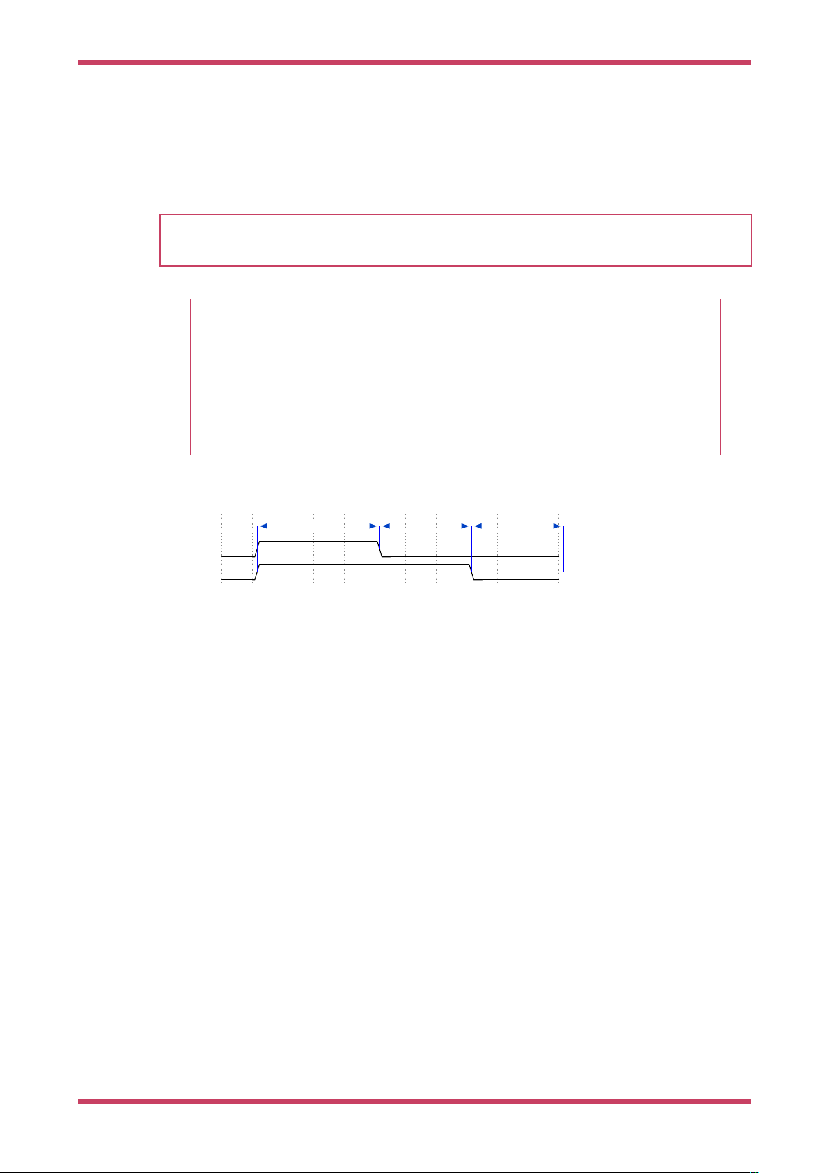
Data=0
Data=1
T1 T2 T3
Pico C/C++ SDK
This matches with the .wrap_target directive at the top of the program. Wrapping is a hardware feature of the state
machine which behaves like a wormhole: you go in through the .wrap statement and appear at the .wrap_target zero cycles
later, unless the .wrap is preceded immediately by a jmp whose condition is true. This is important for getting precise
timing with programs that must run quickly, and often also saves you a slot in the instruction memory.
TIP
Often an explicit .wrap_target/.wrap pair is not necessary, because the default configuration produced by pioasm has an
implicit wrap from the end of the program back to the beginning, if you didn’t specify one.
NOPs
NOP, or no operation, means precisely that: do nothing! You may notice there is no nop instruction defined
in the instruction set reference: nop is really a synonym for mov x, x in PIO assembly.
Why did we insert a nop in this example when we could have jmp-ed? Good question! It’s a dramatic device
we contrived so we could discuss nop and .wrap. Writing documentation is hard. In general, though, nop is
useful when you need to perform a side-set and have nothing else to do, or you need a very slightly longer
delay than is available on a single instruction.
Figure 7. The line is
initially low in the idle
(latch) state, and the
LED is waiting for the
first rising edge. It
sees our pulse timings
in the order T1-T2-T3,
until the very last T3,
where it sees a much
longer negative period
once the state
machine runs out of
data.
It is hopefully becoming clear why our timings T1, T2, T3 are numbered this way, because what the LED string sees really
is one of these two cases:
This should look familiar if you refer back to Figure 3.
After thoroughly dissecting our program, and hopefully being satisfied that it will repeatedly send one well-formed data bit
to a string of WS2812 LEDs, we’re left with a question: where is the data coming from? This is more thoroughly explained
in the RP2040 Datasheet, but the data that we are shifting out from the OSR came from the state machine’s TX FIFO. The
TX FIFO is a data buffer between the state machine and the rest of RP2040, filled either via direct poking from the CPU, or
by the system DMA, which is much faster.
The out instruction shifts data out from the OSR, and zeroes are shifted in from the other end to fill the vacuum. Because
the OSR is 32 bits wide, you will start getting zeroes once you have shifted out a total of 32 bits. There is a pull instruction
which explicitly takes data from the TX FIFO and put it in the OSR (stalling the state machine if the FIFO is empty).
However, in the majority of cases it is simpler to configure autopull, a mode where the state machine automatically refills
the OSR from the TX FIFO (an automatic pull) when a configured number of bits have been shifted out. Autopull happens
in the background, in parallel with whatever else the state machine may be up to (in other words it has a cost of zero
cycles). We’ll see how this is configured in the next section.
3.2.2.2. State Machine Configuration
When we run pioasm on the .pio file we have been looking at, and ask it to spit out Pico SDK code (which is the default), it
will create some static variables describing the program, and a method ws2812_default_program_config which
configures a PIO state machine based on user parameters, and the directives in the actual PIO program (namely the
.side_set and .wrap in this case).
Of course how you configure the PIO SM when using the program is very much related to the program you have written.
Rather than try to store a data representation off all that information, and parse it at runtime, for the use cases where
you’d like to encapsulate setup or other API functions with your PIO program, you can embed code within the .pio file.
3.2. Getting started with PIO 38
Page 40

Pico C/C++ SDK
Pico Examples: https://github.com/raspberrypi/pico-examples/tree/master/pio/ws2812/ws2812.pio Lines 31 - 47
31 static inline void ws2812_program_init(PIO pio, uint sm, uint offset, uint pin, float freq,
Ê bool rgbw) {
32
33 pio_gpio_init(pio, pin);
34 pio_sm_set_consecutive_pindirs(pio, sm, pin, 1, true);
35
36 pio_sm_config c = ws2812_program_get_default_config(offset);
37 sm_config_set_sideset_pins(&c, pin);
38 sm_config_set_out_shift(&c, false, true, rgbw ? 32 : 24);
39 sm_config_set_fifo_join(&c, PIO_FIFO_JOIN_TX);
40
41 int cycles_per_bit = ws2812_T1 + ws2812_T2 + ws2812_T3;
42 float div = clock_get_hz(clk_sys) / (freq * cycles_per_bit);
43 sm_config_set_clkdiv(&c, div);
44
45 pio_sm_init(pio, sm, offset, &c);
46 pio_sm_set_enabled(pio, sm, true);
47 }
In this case we are passing through code for the Pico SDK, as requested by this line you will see if you click the link on the
above listing to see the context:
% c-sdk {
We have here a function ws2812_program_init which is provided to help the user to instantiate an instance of the LED driver
program, based on a handful of parameters:
pio
Which of RP2040’s two PIO instances we are dealing with
sm
Which state machine on that PIO we want to configure to run the WS2812 program
offset
Where the PIO program was loaded in PIO’s 5-bit program address space
pin
which GPIO pin our WS2812 LED chain is connected to
freq
The frequency (or rather baud rate) we want to output data at.
rgbw
True if we are using 4-colour LEDs (red, green, blue, white) rather than the usual 3.
Such that:
pio_gpio_init(pio, pin); Configure a GPIO for use by PIO. (Set the GPIO function select.)
•
pio_set_consecutive_pindirs(pio, sm, pin, 1, true); Sets the PIO pin direction of 1 pin starting at pin number pin to
•
out
pio_sm_config c = ws2812_program_default_config(offset); Get the default configuration using the generated function
•
for this program (this includes things like the .wrap and .side_set configurations from the program). We’ll modify this
configuration before loading it into the state machine.
sm_config_sideset_pins(&c, pin); Sets the side set to write to pins starting at pin pin (we say starting at because if you
•
had .side_set 3, then it would be outputting values on numbers pin, pin+1, pin+2)
3.2. Getting started with PIO 39
Page 41

Pico C/C++ SDK
sm_config_out_shift(&c, false, true, rgbw ? 32 : 24); False for shift_to_right (i.e. we want to shift out MSB first).
•
True for autopull. 32 or 24 for the number of bits for the autopull threshold, i.e. the point at which the state machine
triggers a refill of the OSR, depending on whether the LEDs are RGB or RGBW.
int cycles_per_bit = ws2812_T1 + ws2812_T2 + ws2812_T3; This is the total number of execution cycles to output a
•
single bit. Here we see the benefit of .define public; we can use the T1 - T3 values in our code.
float div = clock_get_hz(clk_sys) / (freq * cycles_per_bit); sm_config_clkdiv(&c, div); Slow the state machine’s
•
execution down, based on the system clock speed and the number of execution cycles required per WS2812 data bit,
so that we achieve the correct bit rate.
pio_sm_init(pio, sm, offset, &c); Load our configuration into the state machine, and go to the start address (offset)
•
pio_sm_enable(pio, sm, true); And make it go now!
•
At this point the program will be stuck on the first out waiting for data. This is because we have autopull enabled, the OSR
is initially empty, and there is no data to be pulled. The state machine refuses to continue until the first piece of data
arrives in the FIFO.
As an aside, this last point sheds some light on the slightly cryptic comment at the start of the PIO program:
Ê out x, 1 side 0 [T3 - 1] ; Side-set still takes place when instruction stalls
This comment is giving us an important piece of context. We stall on this instruction initially, before the first data is added,
and also every time we finish sending the last piece of data at the end of a long serial burst. When a state machine stalls,
it does not continue to the next instruction, rather it will reattempt the current instruction on the next divided clock cycle.
However, side set still takes place. This works in our favour here, because we consequently always return the line to the
idle (low) state when we stall.
3.2.2.3. C Program
The companion to the .pio file we’ve looked at is a .c file which drives some interesting colour patterns out onto a string
of LEDs. We’ll just look at the parts that are directly relevant to PIO.
Pico Examples: https://github.com/raspberrypi/pico-examples/tree/master/pio/ws2812/ws2812.c Lines 15 - 17
15 static inline void put_pixel(uint32_t pixel_grb) {
16 pio_sm_put_blocking(pio0, 0, pixel_grb << 8u);
17 }
Pico Examples: https://github.com/raspberrypi/pico-examples/tree/master/pio/ws2812/ws2812.c Lines 19 - 24
19 static inline uint32_t urgb_u32(uint8_t r, uint8_t g, uint8_t b) {
20 return
21 ((uint32_t) (r) << 8) |
22 ((uint32_t) (g) << 16) |
23 (uint32_t) (b);
24 }
Here we are writing 32-bit values into the FIFO, one at a time, directly from the CPU. pio_sm_put_blocking is a helper method
that waits until there is room in the FIFO before pushing your data.
You’ll notice the << 8 in put_pixel(): remember we are shifting out starting with the MSB, so we want the 24-bit colour
values at the top. this works fine for WGBR too, just that the W is always 0.
This program has a handful of colour patterns, which call our put_pixel helper above to output a sequence of pixel values:
3.2. Getting started with PIO 40
Page 42

Pico C/C++ SDK
Pico Examples: https://github.com/raspberrypi/pico-examples/tree/master/pio/ws2812/ws2812.c Lines 40 - 45
40 void pattern_random(uint len, uint t) {
41 if (t % 8)
42 return;
43 for (int i = 0; i < len; ++i)
44 put_pixel(rand());
45 }
The main function loads the program onto a PIO, configures a state machine for 800 kbaud WS2812 transmission, and
then starts cycling through the colour patterns randomly.
Pico Examples: https://github.com/raspberrypi/pico-examples/tree/master/pio/ws2812/ws2812.c Lines 76 - 100
Ê76 int main() {
Ê77 //set_sys_clock_48();
Ê78 stdio_init_all();
Ê79 puts("WS2812 Smoke Test");
Ê80
Ê81 // todo get free sm
Ê82 PIO pio = pio0;
Ê83 int sm = 0;
Ê84 uint offset = pio_add_program(pio, &ws2812_program);
Ê85
Ê86 ws2812_program_init(pio, sm, offset, PIN_TX, 800000, true);
Ê87
Ê88 int t = 0;
Ê89 while (1) {
Ê90 int pat = rand() % count_of(pattern_table);
Ê91 int dir = (rand() >> 30) & 1 ? 1 : -1;
Ê92 puts(pattern_table[pat].name);
Ê93 puts(dir == 1 ? "(forward)" : "(backward)");
Ê94 for (int i = 0; i < 1000; ++i) {
Ê95 pattern_table[pat].pat(150, t);
Ê96 sleep_ms(10);
Ê97 t += dir;
Ê98 }
Ê99 }
100 }
3.2.3. PIO and DMA (A Logic Analyser)
So far we have looked at writing data to PIO directly from the processor. This often leads to the processor spinning its
wheels waiting for room in a FIFO to make a data transfer, which is not a good investment of its time. It also limits the
total data throughput you can achieve.
RP2040 is equipped with a powerful direct memory access unit (DMA), which can transfer data for you in the background.
Suitably programmed, the DMA can make quite long sequences of transfers without supervision. Up to one word per
system clock can be transferred to or from a PIO state machine, which is, to be quite technically precise, more bandwidth
than you can shake a stick at. The bandwidth is shared across all state machines, but you can use the full amount on one
state machine.
Let’s take a look at the logic_analyser example, which uses PIO to sample some of RP2040’s own pins, and capture a logic
trace of what is going on there, at full system speed.
Pico Examples: https://github.com/raspberrypi/pico-examples/tree/master/pio/logic_analyser/logic_analyser.c Lines 29 - 49
29 void logic_analyser_init(PIO pio, uint sm, uint pin_base, uint pin_count, float div) {
3.2. Getting started with PIO 41
Page 43

Pico C/C++ SDK
30 // Load a program to capture n pins. This is just a single `in pins, n`
31 // instruction with a wrap.
32 uint16_t capture_prog_instr = pio_encode_in(pio_pins, pin_count);
33 struct pio_program capture_prog = {
34 .instructions = &capture_prog_instr,
35 .length = 1,
36 .origin = -1
37 };
38 uint offset = pio_add_program(pio, &capture_prog);
39
40 // Configure state machine to loop over this `in` instruction forever,
41 // with autopush enabled.
42 pio_sm_config c = pio_get_default_sm_config();
43 sm_config_set_in_pins(&c, pin_base);
44 sm_config_set_wrap(&c, offset, offset);
45 sm_config_set_clkdiv(&c, div);
46 sm_config_set_in_shift(&c, true, true, 32);
47 sm_config_set_fifo_join(&c, PIO_FIFO_JOIN_RX);
48 pio_sm_init(pio, sm, offset, &c);
49 }
Our program consists only of a single in pins, <pin_count> instruction, with program wrapping and autopull enabled.
Because the amount of data to be shifted is only known at runtime, and because the program is so short, we are
generating the program dynamically here (using the pio_encode_ functions) instead of pushing it through pioasm. The
program is wrapped in a data structure stating how big the program is, and where it must be loaded — in this case origin
= 1 meaning "don’t care".
Input Shift Register
The input shift register (ISR) is the mirror image of the OSR. Generally data flows through a state machine
in one of two directions: System → TX FIFO → OSR → Pins, or Pins → ISR → RX FIFO → System. An in
instruction shifts data into the ISR.
If you don’t need the ISR’s shifting ability — for example, if your program is output-only — you can use the
ISR as a third scratch register. It’s 32 bits in size, the same as X, Y and the OSR. The full details are in the
RP2040 Datasheet.
We load the program into the chosen PIO, and then configure the input pin mapping on the chosen state machine so that
its in pins instruction will see the pins we care about. For an in instruction we only need to worry about configuring the
base pin, i.e. the pin which is the least significant bit of the in instruction’s sample. The number of pins to be sampled is
determined by the bit count parameter of the in pins instruction — it will sample n pins starting at the base we specified,
and shift them into the ISR.
Pin Groups (Mapping)
We mentioned earlier that there are four pin groups to configure, to connect a state machine’s internal
data buses to the GPIOs it manipulates. A state machine accesses all pins within a group at once, and pin
groups can overlap. So far we have seen the out, side-set and in pin groups. The fourth is set.
The out group is the pins affected by shifting out data from the OSR, using out pins or out pindirs, up to
32 bits at a time. The set group is used with set pins and set pindirs instructions, up to 5 bits at a time,
with data that is encoded directly in the instruction. It’s useful for toggling control signals. The side-set
group is similar to the set group, but runs simultaneously with another instruction. Note: mov pin uses the
in or out group, depending on direction.
Configuring the clock divider optionally slows down the state machine’s execution: a clock divisor of n means 1
instruction will be executed per n system clock cycles. The default system clock frequency for Pico SDK is 125 MHz.
3.2. Getting started with PIO 42
Page 44

Pico C/C++ SDK
sm_config_set_in_shift sets the shift direction to rightward, enables autopush, and sets the autopush threshold to 32. The
state machine keeps an eye on the total amount of data shifted into the ISR, and on the in which reaches or breaches a
total shift count of 32 (or whatever number you have configured), the ISR contents, along with the new data from the in.
goes straight to the RX FIFO. The ISR is cleared to zero in the same operation.
sm_config_set_fifo_join is used to manipulate the FIFOs so that the DMA can get more throughput. If we want to sample
every pin on every clock cycle, that’s a lot of bandwidth! We’ve finished describing how the state machine should be
configured, so we use pio_sm_init to load the configuration into the state machine, and get the state machine into a clean
initial state.
FIFO Joining
Each state machine is equipped with a FIFO going in each direction: the TX FIFO buffers data on its way
out of the system, and the RX FIFO does the same for data coming in. Each FIFO has four data slots, each
holding 32 bits of data. Generally you want FIFOs to be as deep as possible, so there is more slack time
between the timing-critical operation of a peripheral, and data transfers from system agents which may
be quite busy or have high access latency. However this comes with significant hardware cost.
If you are only using one of the two FIFOs — TX or RX — a state machine can pool its resources to provide
a single FIFO with double the depth. The RP2040 Datasheet goes into much more detail, including how
this mechanism actually works under the hood.
Our state machine is ready to sample some pins. Let’s take a look at how we hook up the DMA to our state machine, and
tell the state machine to start sampling once it sees some trigger condition.
Pico Examples: https://github.com/raspberrypi/pico-examples/tree/master/pio/logic_analyser/logic_analyser.c Lines 51 - 70
51 void logic_analyser_arm(PIO pio, uint sm, uint dma_chan, uint32_t *capture_buf, size_t
Ê capture_size_words,
52 uint trigger_pin, bool trigger_level) {
53 pio_sm_set_enabled(pio, sm, false);
54 pio_sm_clear_fifos(pio, sm);
55
56 dma_channel_config c = dma_channel_get_default_config(dma_chan);
57 channel_config_set_read_increment(&c, false);
58 channel_config_set_write_increment(&c, true);
59 channel_config_set_dreq(&c, pio_get_dreq(pio, sm, false));
60
61 dma_channel_configure(dma_chan, &c,
62 capture_buf, // Destinatinon pointer
63 &pio->rxf[sm], // Source pointer
64 capture_size_words, // Number of transfers
65 true // Start immediately
66 );
67
68 pio_sm_exec(pio, sm, pio_encode_wait_gpio(trigger_level, trigger_pin));
69 pio_sm_set_enabled(pio, sm, true);
70 }
We want the DMA to read from the RX FIFO on our PIO state machine, so every DMA read is from the same address. The
write address, on the other hand, should increment after every DMA transfer so that the DMA gradually fills up our capture
buffer as data comes in. We need to specify a data request signal (DREQ) so that the DMA transfers data at the proper
rate.
3.2. Getting started with PIO 43
Page 45

Pico C/C++ SDK
Data request signals
The DMA can transfer data incredibly fast, and almost invariably this will be much faster than your PIO
program actually needs. The DMA paces itself based on a data request handshake with the state
machine, so there’s no worry about it overflowing or underflowing a FIFO, as long as you have selected
the correct DREQ signal. The state machine coordinates with the DMA to tell it when it has room available
in its TX FIFO, or data available in its RX FIFO.
We need to provide the DMA channel with an initial read address, an initial write address, and the total number of
reads/writes to be performed (not the total number of bytes). We start the DMA channel immediately — from this point on,
the DMA is poised, waiting for the state machine to produce data. As soon as data appears in the RX FIFO, the DMA will
pounce and whisk the data away to our capture buffer in system memory.
As things stand right now, the state machine will immediately go into a 1-cycle loop of in instructions once enabled. Since
the system memory available for capture is quite limited, it would be better for the state machine to wait for some trigger
before it starts sampling. Specifically, we are using a wait pin instruction to stall the state machine until a certain pin goes
high or low, and again we are using one of the pio_encode_ functions to encode this instruction on-the-fly.
pio_sm_exec tells the state machine to immediately execute some instruction you give it. This instruction never gets written
to the instruction memory, and if the instruction stalls (as it will in this case — a wait instruction’s job is to stall) then the
state machine will latch the instruction until it completes. With the state machine stalled on the wait instruction, we can
enable it without being immediately flooded by data.
At this point everything is armed and waiting for the trigger signal from the chosen GPIO. This will lead to the following
sequence of events:
1.
The wait instruction will clear
2.
On the very next cycle, state machine will start to execute in instructions from the program memory
3. As soon as data appears in the RX FIFO, the DMA will start to transfer it.
4. Once the requested amount of data has been transferred by the DMA, it’ll automatically stop
State Machine EXEC Functionality
So far our state machines have executed instructions from the instruction memory, but there are other
options. One is the SMx_INSTR register (used by pio_sm_exec()): the state machine will immediately execute
whatever you write here, momentarily interrupting the current program it’s running if necessary. This is
useful for poking around inside the state machine from the system side, for initial setup.
The other two options, which use the same underlying hardware, are out exec (shift out an instruction
from the data being streamed through the OSR, and execute it) and mov exec (execute an instruction
stashed in e.g. a scratch register). Besides making people’s eyes bulge, these are really useful if you want
the state machine to perform some data-defined operation at a certain point in an output stream.
The example code provides this cute function for displaying the captured logic trace as ASCII art in a terminal:
Pico Examples: https://github.com/raspberrypi/pico-examples/tree/master/pio/logic_analyser/logic_analyser.c Lines 72 - 86
72 void print_capture_buf(const uint32_t *buf, uint pin_base, uint pin_count, uint32_t
Ê n_samples) {
73 // Display the capture buffer in text form, like this:
74 // 00: __--__--__--__--__--__--
75 // 01: ____----____----____----
76 printf("Capture:\n");
77 for (int pin = 0; pin < pin_count; ++pin) {
78 printf("%02d: ", pin + pin_base);
79 for (int sample = 0; sample < n_samples; ++sample) {
80 uint bit_index = pin + sample * pin_count;
3.2. Getting started with PIO 44
Page 46

Pico C/C++ SDK
81 bool level = !!(buf[bit_index / 32] & 1u << (bit_index % 32));
82 printf(level ? "-" : "_");
83 }
84 printf("\n");
85 }
86 }
We have everything we need now for RP2040 to capture a logic trace of its own pins, whilst running some other program.
Here we’re setting up a PWM slice to output at around 15 MHz on two GPIOs, and attaching our brand spanking new logic
analyser to those same two GPIOs.
Pico Examples: https://github.com/raspberrypi/pico-examples/tree/master/pio/logic_analyser/logic_analyser.c Lines 88 - 125
Ê88 int main() {
Ê89 stdio_init_all();
Ê90 printf("PIO logic analyser example\n");
Ê91
Ê92 uint32_t capture_buf[(CAPTURE_PIN_COUNT * CAPTURE_N_SAMPLES + 31) / 32];
Ê93
Ê94 PIO pio = pio0;
Ê95 uint sm = 0;
Ê96 uint dma_chan = 0;
Ê97
Ê98 logic_analyser_init(pio, sm, CAPTURE_PIN_BASE, CAPTURE_PIN_COUNT, 1.f);
Ê99
100 printf("Arming trigger\n");
101 logic_analyser_arm(pio, sm, dma_chan, capture_buf, //;
102 (CAPTURE_PIN_COUNT * CAPTURE_N_SAMPLES + 31) / 32,
103 CAPTURE_PIN_BASE, true);
104
105 printf("Starting PWM example\n");
106 // PWM example: -----------------------------------------------------------
107 gpio_set_function(CAPTURE_PIN_BASE, GPIO_FUNC_PWM);
108 gpio_set_function(CAPTURE_PIN_BASE + 1, GPIO_FUNC_PWM);
109 // Topmost value of 3: count from 0 to 3 and then wrap, so period is 4 cycles
110 pwm_hw->slice[0].top = 3;
111 // Divide frequency by two to slow things down a little
112 pwm_hw->slice[0].div = 4 << PWM_CH0_DIV_INT_LSB;
113 // Set channel A to be high for 1 cycle each period (duty cycle 1/4) and
114 // channel B for 3 cycles (duty cycle 3/4)
115 pwm_hw->slice[0].cc =
116 (1 << PWM_CH0_CC_A_LSB) |
117 (3 << PWM_CH0_CC_B_LSB);
118 // Enable this PWM slice
119 pwm_hw->slice[0].csr = PWM_CH0_CSR_EN_BITS;
120 // ------------------------------------------------------------------------
121
122 dma_channel_wait_for_finish_blocking(dma_chan);
123
124 print_capture_buf(capture_buf, CAPTURE_PIN_BASE, CAPTURE_PIN_COUNT, CAPTURE_N_SAMPLES);
125 }
The output of the program looks like this:
Starting PWM example
Capture:
16: ----____________----____________----____________----____________----_______
17: ------------____------------____------------____------------____-----------
3.2. Getting started with PIO 45
Page 47

Pico C/C++ SDK
3.2.4. Further examples
Hopefully what you have seen so far has given some idea of how PIO applications can be built with the Pico SDK. The
RP2040 Datasheet contains many more documented examples, which highlight particular hardware features of PIO, or
show how particular hardware interfaces can be implemented.
You can also browse the pio/ directory in the pico-examples repository.
3.3. Using PIOASM, the PIO Assembler
Up until now, we have glossed over the details of how the assembly program in our .pio file is translated into a binary
program, ready to be loaded into our PIO state machine. Programs that handle this task — translating assembly code into
binary — are generally referred to as assemblers, and PIO is no exception in this regard. The Pico SDK includes an
assembler for PIO, called pioasm. The SDK handles the details of building this tool for you behind the scenes, and then
using it to build your PIO programs, for you to #include from your C or C++ program. pioasm can also be used directly, and
has a few features not used by the C++ SDK, such as generating programs suitable for use with the MicroPython PIO
library.
If you have built the pico-examples repository at any point, you will likely already have a pioasm binary in your build directory,
located under build/tools/pioasm/pioasm, which was bootstrapped for you before building any applications that depend on
it. If we want a standalone copy of pioasm, perhaps just to explore the available commandline options, we can obtain it as
follows (assuming the Pico SDK is extracted at $PICO_SDK_PATH):
mkdir pioasm_build
cd pioasm_build
cmake $PICO_SDK_PATH/tools/pioasm
make
And then invoke as:
./pioasm
3.3.1. Usage
A description of the command line arguments can be obtained by running:
pioasm -?
giving:
usage: pioasm <options> <input> (<output>)
Assemble file of PIO program(s) for use in applications.
<input> the input filename
<output> the output filename (or filename prefix if the output
Ê format produces multiple outputs).
Ê if not specified, a single output will be written to stdout
options:
-o <output_format> select output_format (default 'c-sdk'); available options are:
3.3. Using PIOASM, the PIO Assembler 46
Page 48

Pico C/C++ SDK
Table 5. pioasm
directives
Ê c-sdk
Ê C header suitable for use with the Pico SDK
Ê python
Ê Python file suitable for use with MicroPython
Ê hex
Ê Raw hex output (only valid for single program inputs)
-p <output_param> add a parameter to be passed to the outputter
-?, --help print this help and exit
NOTE
Within the Pico SDK you do not need to invoke pioasm directly, as the CMake function pico_generate_pio_header(TARGET
PIO_FILE) takes care of invoking pioasm and adding the generated header to the include path of the target TARGET for
you.
3.3.2. Directives
The following directives control the assembly of PIO programs:
.define ( PUBLIC ) <symbol> <value> Define an integer symbol named <symbol> with the value <value> (see Section
3.3.3). If this .define appears before the first program in the input file, then the
define is global to all programs, otherwise it is local to the program in which it
occurs. If PUBLIC is specified the symbol will be emitted into the assembled
output for use by user code. For the Pico SDK this takes the form of:
#define <program_name>_<symbol> value for program symbols or #define <symbol>
value for global symbols
.program <name> Start a new program with the name <name>. Note that that name is used in
code so should be alphanumeric/underscore not starting with a digit. The
program lasts until another .program directive or the end of the source file. PIO
instructions are only allowed within a program
.origin <offset> Optional directive to specify the PIO instruction memory offset at which the
program must load. Most commonly this is used for programs that must load
at offset 0, because they use data based JMPs with the (absolute) jmp target
being stored in only a few bits. This directive is invalid outside of a program
.side_set <count> (opt) (pindirs) If this directive is present, <count> indicates the number of side set bits to be
used. Additionally opt may be specified to indicate that a side <value> is
optional for instructions (not using this requires stealing an extra bit - in addition
to the <count> bits - from those available for the instruction delay). Finally,
pindirs may be specified to indicate that the side set values should be applied to
the PINDIRs and not the PINs. This directive is only valid within a program
before the first instruction
.wrap_target Place prior to an instruction, this directive specifies the instruction where
execution continues due to program wrapping. This directive is invalid outside
of a program, may only be used once within a program, and if not specified
defaults to the start of the program
.wrap Placed after an instruction, this directive specifies the instruction after which, in
normal control flow (i.e. jmp with false condition, or no jmp), the program wraps
(to .wrap_target instruction). This directive is invalid outside of a program, may
only be used once within a program, and if not specified defaults to after the
last program instruction.
3.3. Using PIOASM, the PIO Assembler 47
Page 49

Pico C/C++ SDK
Table 6. Values in
pioasm, i.e. <value>
.lang_opt <lang> <name> <option> Specifies an option for the program related to a particular language generator.
(See Section 3.3.9). This directive is invalid outside of a program
.word <value> Stores a raw 16-bit value as an instruction in the program. This directive is
invalid outside of a program.
3.3.3. Values
The following types of values can be used to define integer numbers or branch targets
integer An integer value e.g. 3 or -7
hex
A hexadecimal value e.g. 0xf
Table 7. Expressions
in pioasm i.e.
<expression>
binary
symbol
<label> The instruction offset of the label within the program. This makes most sense when used with a
( <expression> ) An expression to be evaluated; see expressions. Note that the parentheses are necessary.
A binary value e.g. 0b1001
A value defined by a .define (see [pioasm_define])
JMP instruction (see Section 3.4.2)
3.3.4. Expressions
Expressions may be freely (boldly?) used within pioasm values.
<expression> + <expression> The sum of two expressions
<expression> - <expression> The difference of two expressions
<expression> * <expression> The multiplication of two expressions
<expression> / <expression> The integer division of two expressions
- <expression> The negation of another expression
:: <expression> The bit reverse of another expression
<value> Any value (see Section 3.3.3)
3.3.5. Comments
Line comments are supported with // or ;
C-style block comments are supported via /* and */
3.3.6. Labels
Labels are of the form:
<symbol>:
or
PUBLIC <symbol>:
at the start of a line.
3.3. Using PIOASM, the PIO Assembler 48
Page 50

Pico C/C++ SDK
TIP
A label is really just an automatic .define with a value set to the current program instruction offset. A PUBLIC label is
exposed to the user code in the same way as a PUBLIC .define.
3.3.7. Instructions
All pioasm instructions follow a common pattern:
<instruction> (side <side_set_value>) ([<delay_value>])
where:
<instruction> Is an assembly instruction detailed in the following sections. (See Section 3.4)
<side_set_value> Is a value (see Section 3.3.3) to apply to the side_set pins at the start of the instruction. Note that
the rules for a side set value via side <side_set_value> are dependent on the .side_set (see
[pioasm_side_set]) directive for the program. If no .side_set is specified then the side
<side_set_value> is invalid, if an optional number of sideset pins is specified then side
<side_set_value> may be present, and if a non-optional number of sideset pins is specified, then side
<side_set_value> is required. The <side_set_value> must fit within the number of side set bits
specified in the .side_set directive.
<delay_value> Specifies the number of cycles to delay after the instruction completes. The delay_value is specified
as a value (see Section 3.3.3), and in general is between 0 and 31 inclusive (a 5-bit value), however
the number of bits is reduced when sideset is enabled via the .side_set (see [pioasm_side_set])
directive. If the <delay_value> is not present, then the instruction has no delay
NOTE
pioasm instruction names, keywords and directives are case insensitive; lower case is used in the Assembly Syntax
sections below as this is the style used in the Pico SDK.
NOTE
Commas appear in some Assembly Syntax sections below, but are entirely optional, e.g. out pins, 3 may be written out
pins 3, and jmp x-- label may be written as jmp x--, label. The Assembly Syntax sections below uses the first style in
each case as this is the style used in the Pico SDK.
3.3.8. Output pass through
Text in the PIO file may be passed, unmodifed, to the output based on the language generator being used.
For example the following (comment and function) would be included in the generated header when the default c-sdk
language generator is used.
% c-sdk {
// an inline function (since this is going in a header file)
static inline int some_c_code() {
Ê return 0;
}
%}
3.3. Using PIOASM, the PIO Assembler 49
Page 51

Pico C/C++ SDK
The general format is
% target {
pass through contents
%}
with targets being recognized by a particular language generator (see Section 3.3.9; note that target is usually the
language generator name e.g. c-sdk, but could potentially be some_language.some_some_group if the the language generator
supports different classes of pass through with different output locations.
This facility allows you to encapsulate both the PIO program and the associated setup required in the same source file.
See Section 3.3.9 for a more complete example.
3.3.9. Language generators
The following example shows a multi program source file (with multiple programs) which we will use to highlight c-sdk
and python output features
Pico Examples: https://github.com/raspberrypi/pico-examples/tree/master/pio/ws2812/ws2812.pio Lines 1 - 85
Ê1 ;
Ê2 ; Copyright (c) 2020 Raspberry Pi (Trading) Ltd.
Ê3 ;
Ê4 ; SPDX-License-Identifier: BSD-3-Clause
Ê5 ;
Ê6
Ê7 .program ws2812
Ê8 .side_set 1
Ê9
10 .define public T1 2
11 .define public T2 5
12 .define public T3 3
13
14 .lang_opt python sideset_init = pico.PIO.OUT_HIGH
15 .lang_opt python out_init = pico.PIO.OUT_HIGH
16 .lang_opt python out_shiftdir = 1
17
18 .wrap_target
19 bitloop:
20 out x, 1 side 0 [T3 - 1] ; Side-set still takes place when instruction stalls
21 jmp !x do_zero side 1 [T1 - 1] ; Branch on the bit we shifted out. Positive pulse
22 do_one:
23 jmp bitloop side 1 [T2 - 1] ; Continue driving high, for a long pulse
24 do_zero:
25 nop side 0 [T2 - 1] ; Or drive low, for a short pulse
26 .wrap
27
28 % c-sdk {
29 #include "hardware/clocks.h"
30
31 static inline void ws2812_program_init(PIO pio, uint sm, uint offset, uint pin, float freq,
Ê bool rgbw) {
32
33 pio_gpio_init(pio, pin);
34 pio_sm_set_consecutive_pindirs(pio, sm, pin, 1, true);
35
36 pio_sm_config c = ws2812_program_get_default_config(offset);
37 sm_config_set_sideset_pins(&c, pin);
38 sm_config_set_out_shift(&c, false, true, rgbw ? 32 : 24);
3.3. Using PIOASM, the PIO Assembler 50
Page 52

Pico C/C++ SDK
39 sm_config_set_fifo_join(&c, PIO_FIFO_JOIN_TX);
40
41 int cycles_per_bit = ws2812_T1 + ws2812_T2 + ws2812_T3;
42 float div = clock_get_hz(clk_sys) / (freq * cycles_per_bit);
43 sm_config_set_clkdiv(&c, div);
44
45 pio_sm_init(pio, sm, offset, &c);
46 pio_sm_set_enabled(pio, sm, true);
47 }
48 %}
49
50 .program ws2812_parallel
51
52 .define public T1 2
53 .define public T2 5
54 .define public T3 3
55
56 .wrap_target
57 out x, 32
58 mov pins, !null [T1-1]
59 mov pins, x [T2-1]
60 mov pins, null [T3-2]
61 .wrap
62
63 % c-sdk {
64 #include "hardware/clocks.h"
65
66 static inline void ws2812_parallel_program_init(PIO pio, uint sm, uint offset, uint
Ê pin_base, uint pin_count, float freq) {
67 for(uint i=pin_base; i<pin_base+pin_count; i++) {
68 pio_gpio_init(pio, i);
69 }
70 pio_sm_set_consecutive_pindirs(pio, sm, pin_base, pin_count, true);
71
72 pio_sm_config c = ws2812_parallel_program_get_default_config(offset);
73 sm_config_set_out_shift(&c, true, true, 32);
74 sm_config_set_out_pins(&c, pin_base, pin_count);
75 sm_config_set_set_pins(&c, pin_base, pin_count);
76 sm_config_set_fifo_join(&c, PIO_FIFO_JOIN_TX);
77
78 int cycles_per_bit = ws2812_parallel_T1 + ws2812_parallel_T2 + ws2812_parallel_T3;
79 float div = clock_get_hz(clk_sys) / (freq * cycles_per_bit);
80 sm_config_set_clkdiv(&c, div);
81
82 pio_sm_init(pio, sm, offset, &c);
83 pio_sm_set_enabled(pio, sm, true);
84 }
85 %}
3.3.9.1. c-sdk
The c-sdk language generator produces a single header file with all the programs in the PIO source file:
The pass through sections (% c-sdk {) are embedded in the output, and the PUBLIC defines are available via #define
3.3. Using PIOASM, the PIO Assembler 51
Page 53

Pico C/C++ SDK
TIP
pioasm creates a function for each program (e.g. ws2812_program_get_default_config()) returning a pio_sm_config based
on the .side_set, .wrap and .wrap_target settings of the program, which you can then use as a basis for configuration
the PIO state machine.
Pico Examples: https://github.com/raspberrypi/pico-examples/tree/master/pio/ws2812/generated/ws2812.pio.h Lines 1 - 112
ÊÊ1 // -------------------------------------------------- //
ÊÊ2 // This file is autogenerated by pioasm; do not edit! //
ÊÊ3 // -------------------------------------------------- //
ÊÊ4
ÊÊ5 #if !PICO_NO_HARDWARE
ÊÊ6 #include "hardware/pio.h"
ÊÊ7 #endif
ÊÊ8
ÊÊ9 // ------ //
Ê10 // ws2812 //
Ê11 // ------ //
Ê12
Ê13 #define ws2812_wrap_target 0
Ê14 #define ws2812_wrap 3
Ê15
Ê16 #define ws2812_T1 2
Ê17 #define ws2812_T2 5
Ê18 #define ws2812_T3 3
Ê19
Ê20 static const uint16_t ws2812_program_instructions[] = {
Ê21 // .wrap_target
Ê22 0x6221, // 0: out x, 1 side 0 [2]
Ê23 0x1123, // 1: jmp !x, 3 side 1 [1]
Ê24 0x1400, // 2: jmp 0 side 1 [4]
Ê25 0xa442, // 3: nop side 0 [4]
Ê26 // .wrap
Ê27 };
Ê28
Ê29 #if !PICO_NO_HARDWARE
Ê30 static const struct pio_program ws2812_program = {
Ê31 .instructions = ws2812_program_instructions,
Ê32 .length = 4,
Ê33 .origin = -1,
Ê34 };
Ê35
Ê36 static inline pio_sm_config ws2812_program_get_default_config(uint offset) {
Ê37 pio_sm_config c = pio_get_default_sm_config();
Ê38 sm_config_set_wrap(&c, offset + ws2812_wrap_target, offset + ws2812_wrap);
Ê39 sm_config_set_sideset(&c, 1, false, false);
Ê40 return c;
Ê41 }
Ê42
Ê43 #include "hardware/clocks.h"
Ê44 static inline void ws2812_program_init(PIO pio, uint sm, uint offset, uint pin, float freq,
Ê bool rgbw) {
Ê45 pio_gpio_init(pio, pin);
Ê46 pio_sm_set_consecutive_pindirs(pio, sm, pin, 1, true);
Ê47 pio_sm_config c = ws2812_program_get_default_config(offset);
Ê48 sm_config_set_sideset_pins(&c, pin);
Ê49 sm_config_set_out_shift(&c, false, true, rgbw ? 32 : 24);
Ê50 sm_config_set_fifo_join(&c, PIO_FIFO_JOIN_TX);
Ê51 int cycles_per_bit = ws2812_T1 + ws2812_T2 + ws2812_T3;
Ê52 float div = clock_get_hz(clk_sys) / (freq * cycles_per_bit);
3.3. Using PIOASM, the PIO Assembler 52
Page 54

Pico C/C++ SDK
Ê53 sm_config_set_clkdiv(&c, div);
Ê54 pio_sm_init(pio, sm, offset, &c);
Ê55 pio_sm_set_enabled(pio, sm, true);
Ê56 }
Ê57
Ê58 #endif
Ê59
Ê60 // --------------- //
Ê61 // ws2812_parallel //
Ê62 // --------------- //
Ê63
Ê64 #define ws2812_parallel_wrap_target 0
Ê65 #define ws2812_parallel_wrap 3
Ê66
Ê67 #define ws2812_parallel_T1 2
Ê68 #define ws2812_parallel_T2 5
Ê69 #define ws2812_parallel_T3 3
Ê70
Ê71 static const uint16_t ws2812_parallel_program_instructions[] = {
Ê72 // .wrap_target
Ê73 0x6020, // 0: out x, 32
Ê74 0xa10b, // 1: mov pins, !null [1]
Ê75 0xa401, // 2: mov pins, x [4]
Ê76 0xa103, // 3: mov pins, null [1]
Ê77 // .wrap
Ê78 };
Ê79
Ê80 #if !PICO_NO_HARDWARE
Ê81 static const struct pio_program ws2812_parallel_program = {
Ê82 .instructions = ws2812_parallel_program_instructions,
Ê83 .length = 4,
Ê84 .origin = -1,
Ê85 };
Ê86
Ê87 static inline pio_sm_config ws2812_parallel_program_get_default_config(uint offset) {
Ê88 pio_sm_config c = pio_get_default_sm_config();
Ê89 sm_config_set_wrap(&c, offset + ws2812_parallel_wrap_target, offset +
Ê ws2812_parallel_wrap);
Ê90 return c;
Ê91 }
Ê92
Ê93 #include "hardware/clocks.h"
Ê94 static inline void ws2812_parallel_program_init(PIO pio, uint sm, uint offset, uint
Ê pin_base, uint pin_count, float freq) {
Ê95 for(uint i=pin_base; i<pin_base+pin_count; i++) {
Ê96 pio_gpio_init(pio, i);
Ê97 }
Ê98 pio_sm_set_consecutive_pindirs(pio, sm, pin_base, pin_count, true);
Ê99 pio_sm_config c = ws2812_parallel_program_get_default_config(offset);
100 sm_config_set_out_shift(&c, true, true, 32);
101 sm_config_set_out_pins(&c, pin_base, pin_count);
102 sm_config_set_set_pins(&c, pin_base, pin_count);
103 sm_config_set_fifo_join(&c, PIO_FIFO_JOIN_TX);
104 int cycles_per_bit = ws2812_parallel_T1 + ws2812_parallel_T2 + ws2812_parallel_T3;
105 float div = clock_get_hz(clk_sys) / (freq * cycles_per_bit);
106 sm_config_set_clkdiv(&c, div);
107 pio_sm_init(pio, sm, offset, &c);
108 pio_sm_set_enabled(pio, sm, true);
109 }
110
111 #endif
3.3. Using PIOASM, the PIO Assembler 53
Page 55

Pico C/C++ SDK
3.3.9.2. python
The python language generator produces a single python file with all the programs in the PIO source file:
The pass through sections (% python {) would be embedded in the output, and the PUBLIC defines are available as python
variables.
Also note the use of .lang_opt python to pass initializers for the @pico.asm_pio decorator
TIP
The python language output is provided as a utility. MicroPython supports programming with the PIO natively, so you
may only want to use pioasm when sharing PIO code between the Pico SDK and MicroPython. No effort is currently
made to preserve label names, symbols or comments, as it is assumed you are either using the PIO file as a source or
python; not both. The python language output can of course be used to bootstrap your MicroPython PIO development
based on an existing PIO file.
Pico Examples: https://github.com/raspberrypi/pico-examples/tree/master/pio/ws2812/generated/ws2812.py Lines 1 - 46
Ê1 # -------------------------------------------------- #
Ê2 # This file is autogenerated by pioasm; do not edit! #
Ê3 # -------------------------------------------------- #
Ê4
Ê5 import rp2
Ê6 from machine import Pin
Ê7 # ------ #
Ê8 # ws2812 #
Ê9 # ------ #
10
11 ws2812_T1 = 2
12 ws2812_T2 = 5
13 ws2812_T3 = 3
14
15 @rp2.asm_pio(sideset_init=pico.PIO.OUT_HIGH, out_init=pico.PIO.OUT_HIGH, out_shiftdir=1)
16 def ws2812():
17 wrap_target()
18 label("0")
19 out(x, 1) .side(0) [2] # 0
20 jmp(not_x, "3") .side(1) [1] # 1
21 jmp("0") .side(1) [4] # 2
22 label("3")
23 nop() .side(0) [4] # 3
24 wrap()
25
26
27
28 # --------------- #
29 # ws2812_parallel #
30 # --------------- #
31
32 ws2812_parallel_T1 = 2
33 ws2812_parallel_T2 = 5
34 ws2812_parallel_T3 = 3
35
36 @rp2.asm_pio()
37 def ws2812_parallel():
38 wrap_target()
39 out(x, 32) # 0
40 mov(pins, not null) [1] # 1
41 mov(pins, x) [4] # 2
42 mov(pins, null) [1] # 3
43 wrap()
3.3. Using PIOASM, the PIO Assembler 54
Page 56

Pico C/C++ SDK
3.3.9.3. hex
The hex generator only supports a single input program, as it just dumps the raw instructions (one per line) as a 4-bit
hexadecimal number.
Given:
Pico Examples: https://github.com/raspberrypi/pico-examples/tree/master/pio/squarewave/squarewave.pio Lines 1 - 13
Ê1 ;
Ê2 ; Copyright (c) 2020 Raspberry Pi (Trading) Ltd.
Ê3 ;
Ê4 ; SPDX-License-Identifier: BSD-3-Clause
Ê5 ;
Ê6
Ê7 .program squarewave
Ê8 set pindirs, 1 ; Set pin to output
Ê9 again:
10 set pins, 1 [1] ; Drive pin high and then delay for one cycle
11 set pins, 0 ; Drive pin low
12 jmp again ; Set PC to label `again`
Table 8. PIO
instruction encoding
The hex output produces:
Pico Examples: https://github.com/raspberrypi/pico-examples/tree/master/pio/squarewave/generated/squarewave.hex Lines 1 - 4
e081
e101
e000
0001
3.4. PIO Instruction Set Reference
NOTE
This section refers in places to concepts and pieces of hardware discussed in the RP2040 Datasheet. You are
encouraged to read the PIO chapter of the datasheet to get the full context for what these instructions do.
3.4.1. Summary
PIO instructions are 16 bits long, and have the following encoding:
Bit: 15 14 13 12 11 10 9 8 7 6 5 4 3 2 1 0
JMP
0 0 0 Delay/side-set Condition Address
WAIT
IN
OUT
PUSH
PULL
MOV
0 0 1 Delay/side-set Pol Source Index
0 1 0 Delay/side-set Source Bit count
0 1 1 Delay/side-set Destination Bit count
1 0 0 Delay/side-set 0 IfF Blk 0 0 0 0 0
1 0 0 Delay/side-set 1 IfE Blk 0 0 0 0 0
1 0 1 Delay/side-set Destination Op Source
3.4. PIO Instruction Set Reference 55
Page 57

Pico C/C++ SDK
Bit: 15 14 13 12 11 10 9 8 7 6 5 4 3 2 1 0
IRQ
SET
All PIO instructions execute in one clock cycle.
The Delay/side-set field is present in all instructions. Its exact use is configured for each state machine by
PINCTRL_SIDESET_COUNT:
1 1 0 Delay/side-set 0 Clr Wait Index
1 1 1 Delay/side-set Destination Data
Up to 5 MSBs encode a side-set operation, which optionally asserts a constant value onto some GPIOs, concurrently
•
with main instruction execution logic
Remaining LSBs (up to 5) encode the number of idle cycles inserted between this instruction and the next
•
3.4.2. JMP
3.4.2.1. Encoding
Bit: 15 14 13 12 11 10 9 8 7 6 5 4 3 2 1 0
JMP
3.4.2.2. Operation
0 0 0 Delay/side-set Condition Address
Set program counter to Address if Condition is true, otherwise no operation.
Delay cycles on a JMP always take effect, whether Condition is true or false, and they take place after Condition is evaluated
and the program counter is updated.
Condition:
•
000: (no condition): Always
◦
001: !X: scratch X zero
◦
010: X--: scratch X non-zero, post-decrement
◦
011: !Y: scratch Y zero
◦
100: Y--: scratch Y non-zero, post-decrement
◦
101: X!=Y: scratch X not equal scratch Y
◦
110: PIN: branch on input pin
◦
111: !OSRE: output shift register not empty
◦
Address: Instruction address to jump to. In the instruction encoding this is an absolute address within the PIO
•
instruction memory.
JMP PIN branches on the GPIO selected by EXECCTRL_JMP_PIN. The branch is taken if the GPIO is high.
!OSRE compares the bits shifted out since the last PULL with the shift count threshold configured by SHIFTCTRL_PULL_THRESH.
This is the same threshold used by autopull.
3.4.2.3. Assembler Syntax
jmp ( <cond> ) <target>
where:
3.4. PIO Instruction Set Reference 56
Page 58

Pico C/C++ SDK
<cond>
<target> Is a program label or value (see Section 3.3.3) representing instruction offset within the program (the
Is an optional condition listed above (e.g. !x for scratch X zero). If a condition code is not specified, the
branch is always taken
first instruction being offset 0). Note that because the PIO JMP instruction uses absolute addresses in
the PIO instruction memory, JMPs need to be adjusted based on the program load offset at runtime.
This is handled for you when loading a program with the Pico SDK, but care should be taken when
encoding JMP instructions for use by OUT EXEC
3.4.3. WAIT
3.4.3.1. Encoding
Bit: 15 14 13 12 11 10 9 8 7 6 5 4 3 2 1 0
WAIT
3.4.3.2. Operation
Stall until some condition is met.
0 0 1 Delay/side-set Pol Source Index
Like all stalling instructions, delay cycles begin after the instruction completes. That is, if any delay cycles are present, they
do not begin counting until after the wait condition is met.
Polarity:
•
1: wait for a 1.
◦
0: wait for a 0.
◦
Source: what to wait on. Values are:
•
00: GPIO: System GPIO input selected by Index. This is an absolute GPIO index, and is not affected by the state
◦
machine’s input IO mapping.
01: PIN: Input pin selected by Index. This state machine’s input IO mapping is applied first, and then Index selects
◦
which of the mapped bits to wait on.
10: IRQ: PIO IRQ flag selected by Index
◦
11: Reserved
◦
Index: which pin or bit to check.
•
WAIT x IRQ behaves slightly differently from other WAIT sources:
If Polarity is 1, the selected IRQ flag is cleared by the state machine upon the wait condition being met.
•
The flag index is decoded in the same way as the IRQ index field: if the MSB is set, the state machine ID (0…3) is
•
added to the IRQ index, by way of modulo-4 addition on the two LSBs. For example, state machine 2 with a flag value
of '0x11' will wait on flag 3, and a flag value of '0x13' will wait on flag 1. This allows multiple state machines running
the same program to synchronise with each other.
3.4. PIO Instruction Set Reference 57
Page 59

Pico C/C++ SDK
CAUTION
WAIT 1 IRQ x should not be used with IRQ flags presented to the interrupt controller, to avoid a race condition with a
system interrupt handler
3.4.3.3. Assembler Syntax
wait <polarity> gpio <gpio_num>
wait <polarity> pin <pin_num>
wait <polarity> irq <irq_num> ( rel )
where:
<polarity> Is a value (see Section 3.3.3) specifying the polarity (either 0 or 1)
<pin_num> Is a value (see Section 3.3.3) specifying the input pin number (as mapped by the SM input pin
mapping)
<gpio_num> Is a value (see Section 3.3.3) specifying the actual GPIO pin number
<irq_num> ( rel ) Is a value (see Section 3.3.3) specifying The irq number to wait on (0-7). If rel is present, then the
actual irq number used is calculating by replacing the low two bits of the irq number (irq_num10) with
the low two bits of the sum (irq_num10 + sm_num10) where sm_num10 is the state machine number
3.4.4. IN
3.4.4.1. Encoding
Bit: 15 14 13 12 11 10 9 8 7 6 5 4 3 2 1 0
IN
3.4.4.2. Operation
Shift Bit count bits from Source into the Input Shift Register (ISR). Shift direction is configured for each state machine by
SHIFTCTRL_IN_SHIFTDIR. Additionally, increase the input shift count by Bit count, saturating at 32.
If automatic push is enabled, IN will also push the ISR contents to the RX FIFO if the push threshold is reached
0 1 0 Delay/side-set Source Bit count
Source:
•
000: PINS
◦
001: X (scratch register X)
◦
010: Y (scratch register Y)
◦
011: NULL (all zeroes)
◦
100: Reserved
◦
101: Reserved
◦
110: ISR
◦
111: OSR
◦
Bit count: How many bits to shift into the ISR. 1…32 bits, 32 is encoded as 00000.
•
3.4. PIO Instruction Set Reference 58
Page 60

Pico C/C++ SDK
(SHIFTCTRL_PUSH_THRESH). IN still executes in one cycle, whether an automatic push takes place or not. The state machine
will stall if the RX FIFO is full when an automatic push occurs. An automatic push clears the ISR contents to all-zeroes,
and clears the input shift count.
IN always uses the least significant Bit count bits of the source data. For example, if PINCTRL_IN_BASE is set to 5, the
instruction IN 3, PINS will take the values of pins 5, 6 and 7, and shift these into the ISR. First the ISR is shifted to the left
or right to make room for the new input data, then the input data is copied into the gap this leaves. The bit order of the
input data is not dependent on the shift direction.
NULL can be used for shifting the ISR’s contents. For example, UARTs receive the LSB first, so must shift to the right. After
8 IN PINS, 1 instructions, the input serial data will occupy bits 31…24 of the ISR. An IN NULL, 24 instruction will shift in 24
zero bits, aligning the input data at ISR bits 7…0. Alternatively, the processor or DMA could perform a byte read from FIFO
address + 3, which would take bits 31…24 of the FIFO contents.
3.4.4.3. Assembler Syntax
in <source>, <bit_count>
where:
<source> Is one of the sources specified above.
<bit_count> Is a value (see Section 3.3.3) specifying the number of bits to shift (valid range 1-32)
3.4.5. OUT
3.4.5.1. Encoding
Bit: 15 14 13 12 11 10 9 8 7 6 5 4 3 2 1 0
OUT
3.4.5.2. Operation
Shift Bit count bits out of the Output Shift Register (OSR), and write those bits to Destination. Additionally, increase the
output shift count by Bit count, saturating at 32.
A 32-bit value is written to Destination: the lower Bit count bits come from the OSR, and the remainder are zeroes. This
value is the least significant Bit count bits of the OSR if SHIFTCTRL_OUT_SHIFTDIR is to the right, otherwise it is the most
significant bits.
0 1 1 Delay/side-set Destination Bit count
Destination:
•
000: PINS
◦
001: X (scratch register X)
◦
010: Y (scratch register Y)
◦
011: NULL (discard data)
◦
100: PINDIRS
◦
101: PC
◦
110: ISR (also sets ISR shift counter to Bit count)
◦
111: EXEC (Execute OSR shift data as instruction)
◦
Bit count: how many bits to shift out of the OSR. 1…32 bits, 32 is encoded as 00000.
•
3.4. PIO Instruction Set Reference 59
Page 61

Pico C/C++ SDK
PINS and PINDIRS use the OUT pin mapping.
If automatic pull is enabled, the OSR is automatically refilled from the TX FIFO if the pull threshold, SHIFTCTRL_PULL_THRESH,
is reached. The output shift count is simultaneously cleared to 0. In this case, the OUT will stall if the TX FIFO is empty, but
otherwise still executes in one cycle.
OUT EXEC allows instructions to be included inline in the FIFO datastream. The OUT itself executes on one cycle, and the
instruction from the OSR is executed on the next cycle. There are no restrictions on the types of instructions which can be
executed by this mechanism. Delay cycles on the initial OUT are ignored, but the executee may insert delay cycles as
normal.
OUT PC behaves as an unconditional jump to an address shifted out from the OSR.
3.4.5.3. Assembler Syntax
out <destination>, <bit_count>
where:
<destination> Is one of the destinations specified above.
<bit_count> Is a value (see Section 3.3.3) specifying the number of bits to shift (valid range 1-32)
3.4.6. PUSH
3.4.6.1. Encoding
Bit: 15 14 13 12 11 10 9 8 7 6 5 4 3 2 1 0
PUSH
3.4.6.2. Operation
Push the contents of the ISR into the RX FIFO, as a single 32-bit word. Clear ISR to all-zeroes.
PUSH IFFULL helps to make programs more compact, like autopush. It is useful in cases where the IN would stall at an
inappropriate time if autopush were enabled, e.g. if the state machine is asserting some external control signal at this
point.
3.4.6.3. Assembler Syntax
1 0 0 Delay/side-set 0 IfF Blk 0 0 0 0 0
IfFull: If 1, do nothing unless the total input shift count has reached its threshold, SHIFTCTRL_PUSH_THRESH (the same as
•
for autopush).
Block: If 1, stall execution if RX FIFO is full.
•
push ( iffull )
push ( iffull ) block
push ( iffull ) noblock
where:
iffull
block
3.4. PIO Instruction Set Reference 60
Is equivalent to IfFull == 1 above. i.e. the default if this is not specified is IfFull == 0
Is equivalent to Block == 1 above. This is the default if neither block nor noblock are specified
Page 62

Pico C/C++ SDK
noblock
Is equivalent to Block == 0 above.
3.4.7. PULL
3.4.7.1. Encoding
Bit: 15 14 13 12 11 10 9 8 7 6 5 4 3 2 1 0
PULL
3.4.7.2. Operation
Load a 32-bit word from the TX FIFO into the OSR.
Some peripherals (UART, SPI…) should halt when no data is available, and pick it up as it comes in; others (I2S) should
clock continuously, and it is better to output placeholder or repeated data than to stop clocking. This can be achieved with
the Block parameter.
1 0 0 Delay/side-set 1 IfE Blk 0 0 0 0 0
IfEmpty: If 1, do nothing unless the total output shift count has reached its threshold, SHIFTCTRL_PULL_THRESH (the same
•
as for autopull).
Block: If 1, stall if TX FIFO is empty. If 0, pulling from an empty FIFO copies scratch X to OSR.
•
A nonblocking PULL on an empty FIFO has the same effect as MOV OSR, X. The program can either preload scratch register
X with a suitable default, or execute a MOV X, OSR after each PULL NOBLOCK, so that the last valid FIFO word will be recycled
until new data is available.
PULL IFEMPTY is useful if an OUT with autopull would stall in an inappropriate location when the TX FIFO is empty. For
example, a UART transmitter should not stall immediately after asserting the start bit. IfEmpty permits some of the same
program simplifications as autopull, but the stall occurs at a controlled point in the program.
3.4.7.3. Assembler Syntax
pull ( ifempty )
pull ( ifempty ) block
pull ( ifempty ) noblock
where:
ifempty
block
noblock
Is equivalent to IfEmpty == 1 above. i.e. the default if this is not specified is IfEmpty == 0
Is equivalent to Block == 1 above. This is the default if neither block nor noblock are specified
Is equivalent to Block == 0 above.
3.4.8. MOV
3.4.8.1. Encoding
Bit: 15 14 13 12 11 10 9 8 7 6 5 4 3 2 1 0
MOV
3.4. PIO Instruction Set Reference 61
1 0 1 Delay/side-set Destination Op Source
Page 63

Pico C/C++ SDK
3.4.8.2. Operation
Copy data from Source to Destination.
Destination:
•
000: PINS (Uses same pin mapping as OUT)
◦
001: X (Scratch register X)
◦
010: Y (Scratch register Y)
◦
011: Reserved
◦
100: EXEC (Execute data as instruction)
◦
101: PC
◦
110: ISR (Input shift counter is reset to 0 by this operation, i.e. empty)
◦
111: OSR (Output shift counter is reset to 0 by this operation, i.e. full)
◦
Operation:
•
00: None
◦
01: Invert (bitwise complement)
◦
10: Bit-reverse
◦
11: Reserved
◦
Source:
•
000: PINS (Uses same pin mapping as IN)
◦
001: X
◦
010: Y
◦
011: NULL
◦
100: Reserved
◦
101: STATUS
◦
110: ISR
◦
111: OSR
◦
MOV PC causes an unconditional jump. MOV EXEC has the same behaviour as OUT EXEC (Section 3.4.5), and allows register
contents to be executed as an instruction. The MOV itself executes in 1 cycle, and the instruction in Source on the next cycle.
Delay cycles on MOV EXEC are ignored, but the executee may insert delay cycles as normal.
The STATUS source has a value of all-ones or all-zeroes, depending on some state machine status such as FIFO full/empty,
configured by EXECCTRL_STATUS_SEL.
MOV can manipulate the transferred data in limited ways, specified by the Operation argument. Invert sets each bit in
Destination to the logical NOT of the corresponding bit in Source, i.e. 1 bits become 0 bits, and vice versa. Bit reverse sets
each bit n in Destination to bit 31 - n in Source, assuming the bits are numbered 0 to 31.
3.4.8.3. Assembler Syntax
mov <destination>, ( op ) <source>
where:
<destination> Is one of the destinations specified above.
3.4. PIO Instruction Set Reference 62
Page 64

Pico C/C++ SDK
<op> If present, is:
! or ~ for NOT (Note: this is always a bitwise NOT)
:: for bit reverse
<source> Is one of the sources specified above.
3.4.9. IRQ
3.4.9.1. Encoding
Bit: 15 14 13 12 11 10 9 8 7 6 5 4 3 2 1 0
IRQ
1 1 0 Delay/side-set 0 Clr Wait Index
3.4.9.2. Operation
Set or clear the IRQ flag selected by Index argument.
Clear: if 1, clear the flag selected by Index, instead of raising it. If Clear is set, the Wait bit has no effect.
•
Wait: if 1, halt until the raised flag is lowered again, e.g. if a system interrupt handler has acknowledged the flag.
•
Index:
•
The 3 LSBs specify an IRQ index from 0-7. This IRQ flag will be set/cleared depending on the Clear bit.
◦
If the MSB is set, the state machine ID (0…3) is added to the IRQ index, by way of modulo-4 addition on the two
◦
LSBs. For example, state machine 2 with a flag value of 0x11 will raise flag 3, and a flag value of 0x13 will raise
flag 1.
IRQ flags 4-7 are visible only to the state machines; IRQ flags 0-3 can be routed out to system level interrupts, on either of
the PIO’s two external interrupt request lines, configured by IRQ0_INTE and IRQ1_INTE.
The modulo addition bit allows relative addressing of 'IRQ' and 'WAIT' instructions, for synchronising state machines
which are running the same program. Bit 2 (the third LSB) is unaffected by this addition.
If Wait is set, Delay cycles do not begin until after the wait period elapses.
3.4.9.3. Assembler Syntax
irq <irq_num> ( _rel )
irq set <irq_num> ( _rel )
irq nowait <irq_num> ( _rel )
irq wait <irq_num> ( _rel )
irq clear <irq_num> ( _rel )
where:
<irq_num> ( rel ) Is a value (see Section 3.3.3) specifying The irq number to wait on (0-7). If rel is present, then the
actual irq number used is calculating by replacing the low two bits of the irq number (irq_num10) with
the low two bits of the sum (irq_num10 + sm_num10) where sm_num10 is the state machine number
irq Means set the IRQ without waiting
3.4. PIO Instruction Set Reference 63
Page 65

Pico C/C++ SDK
irq set Also means set the IRQ without waiting
irq nowait Again, means set the IRQ without waiting
irq wait Means set the IRQ and wait for it to be cleared before proceeding
irq clear Means clear the IRQ
3.4.10. SET
3.4.10.1. Encoding
Bit: 15 14 13 12 11 10 9 8 7 6 5 4 3 2 1 0
SET
1 1 1 Delay/side-set Destination Data
3.4.10.2. Operation
Write immediate value Data to Destination.
Destination:
•
000: PINS
•
001: X (scratch register X) 5 LSBs are set to Data, all others cleared to 0.
•
010: Y (scratch register Y) 5 LSBs are set to Data, all others cleared to 0.
•
011: Reserved
•
100: PINDIRS
•
101: Reserved
•
110: Reserved
•
111: Reserved
•
Data: 5-bit immediate value to drive to pins or register.
•
This can be used to assert control signals such as a clock or chip select, or to initialise loop counters. As Data is 5 bits in
size, scratch registers can be SET to values from 0-31, which is sufficient for a 32-iteration loop.
The mapping of SET and OUT onto pins is configured independently. They may be mapped to distinct locations, for example
if one pin is to be used as a clock signal, and another for data. They may also be overlapping ranges of pins: a UART
transmitter might use SET to assert start and stop bits, and OUT instructions to shift out FIFO data to the same pins.
3.4.10.3. Assembler Syntax
set <destination>, <value>
where:
<destination> Is one of the destinations specified above.
<value> The value (see Section 3.3.3) to set (valid range 0-31)
3.4. PIO Instruction Set Reference 64
Page 66

Pico C/C++ SDK
Chapter 4. Library Documentation
4.1. Hardware APIs
This group of libraries provides a thin and efficient C API / abstractions to access the RP2040 hardware without having to
read and write hardware registers directly.
hardware_adc Analog to Digital Converter (ADC) API.
hardware_base Low-level types and (atomic) accessors for memory-mapped hardware registers.
hardware_claim Lightweight hardware resource management.
hardware_clocks Clock Management API.
hardware_divider Low-level hardware-divider access.
hardware_dma DMA Controller API.
ÊÊÊÊchannel_config DMA channel configuration.
hardware_flash Low level flash programming and erase API.
hardware_gpio General Purpose Input/Output (GPIO) API.
hardware_i2c I2C Controller API.
hardware_interp Hardware Interpolator API.
ÊÊÊÊinterp_config Interpolator configuration.
hardware_irq Hardware interrupt handling.
hardware_pio Programmable I/O (PIO) API.
ÊÊÊÊsm_config PIO state machine configuration.
hardware_pll Phase Locked Loop control APIs.
hardware_pwm Hardware Pulse Width Modulation (PWM) API.
hardware_resets Hardware Reset API.
hardware_rtc Hardware Real Time Clock API.
hardware_spi Hardware SPI API.
hardware_sync Low level hardware spin-lock, barrier and processor event API.
hardware_timer Low-level hardware timer API.
hardware_uart Hardware UART API.
hardware_vreg Voltage Regulation API.
hardware_watchdog Hardware Watchdog Timer API.
hardware_xosc Crystal Oscillator (XOSC) API.
4.1.1. hardware_adc
Analog to Digital Converter (ADC) API.
4.1. Hardware APIs 65
Page 67

Pico C/C++ SDK
The RP2040 has an internal analogue-digital converter (ADC) with the following features:
SAR ADC
•
500 kS/s (Using an independent 48MHz clock)
•
12 bit (9.5 ENOB)
•
5 input mux:
•
4 inputs that are available on package pins shared with GPIO[29:26]
•
1 input is dedicated to the internal temperature sensor
•
4 element receive sample FIFO
•
Interrupt generation
•
DMA interface
•
Although there is only one ADC you can specify the input to it using the adc_select_input() function. In round robin mode
(adc_rrobin()) will use that input and move to the next one after a read.
User ADC inputs are on 0-3 (GPIO 26-29), the temperature sensor is on input 4.
Temperature sensor values can be approximated in centigrade as:
T = 27 - (ADC_Voltage - 0.706)/0.001721
The FIFO, if used, can contain up to 4 entries.
Example
Ê1 #include <stdio.h>
Ê2 #include "pico/stdlib.h"
Ê3 #include "hardware/gpio.h"
Ê4 #include "hardware/adc.h"
Ê5
Ê6 int main() {
Ê7 stdio_init_all();
Ê8 printf("ADC Example, measuring GPIO26\n");
Ê9
10 adc_init();
11
12 // Make sure GPIO is high-impedance, no pullups etc
13 adc_gpio_init(26);
14 // Select ADC input 0 (GPIO26)
15 adc_select_input(0);
16
17 while (1) {
18 // 12-bit conversion, assume max value == ADC_VREF == 3.3 V
19 const float conversion_factor = 3.3f / (1 << 12);
20 uint16_t result = adc_read();
21 printf("Raw value: 0x%03x, voltage: %f V\n", result, result * conversion_factor);
22 sleep_ms(500);
23 }
24 }
4.1.1.1. Function List
void adc_init (void)
•
static void adc_gpio_init (uint gpio)
•
static void adc_select_input (uint input)
•
4.1. Hardware APIs 66
Page 68

Pico C/C++ SDK
static void adc_set_round_robin (uint input_mask)
•
static void adc_set_temp_sensor_enabled (bool enable)
•
static uint16_t adc_read (void)
•
static void adc_run (bool run)
•
static void adc_set_clkdiv (float clkdiv)
•
static void adc_fifo_setup (bool en, bool dreq_en, uint16_t dreq_thresh, bool err_in_fifo, bool byte_shift)
•
static bool adc_fifo_is_empty (void)
•
static uint8_t adc_fifo_get_level (void)
•
static uint16_t adc_fifo_get (void)
•
static uint16_t adc_fifo_get_blocking (void)
•
static void adc_fifo_drain (void)
•
static void adc_irq_set_enabled (bool enabled)
•
4.1.1.2. Function Documentation
4.1.1.2.1. adc_fifo_drain
static void adc_fifo_drain (void)
Drain the ADC FIFO.
Will wait for any conversion to complete then drain the FIFO discarding any results.
4.1.1.2.2. adc_fifo_get
static uint16_t adc_fifo_get (void)
Get ADC result from FIFO.
Pops the latest result from the ADC FIFO.
4.1.1.2.3. adc_fifo_get_blocking
static uint16_t adc_fifo_get_blocking (void)
Wait for the ADC FIFO to have data.
Blocks until data is present in the FIFO
4.1.1.2.4. adc_fifo_get_level
static uint8_t adc_fifo_get_level (void)
Get number of entries in the ADC FIFO.
The ADC FIFO is 4 entries long. This function will return how many samples are currently present.
4.1.1.2.5. adc_fifo_is_empty
static bool adc_fifo_is_empty (void)
Check FIFO empty state.
4.1. Hardware APIs 67
Page 69

Pico C/C++ SDK
Returns
Returns true if the fifo is empty
•
4.1.1.2.6. adc_fifo_setup
static void adc_fifo_setup (bool en,
КККККК bool dreq_en,
КККККК uint16_t dreq_thresh,
КККККК bool err_in_fifo,
КККККК bool byte_shift)
Setup the ADC FIFO.
FIFO is 4 samples long, if a conversion is completed and the FIFO is full the result is dropped.
Parameters
en Enables write each conversion result to the FIFO
•
dreq_en Enable DMA requests when FIFO contains data
•
dreq_thresh Threshold for DMA requests/FIFO IRQ if enabled.
•
err_in_fifo If enabled, bit 15 of the FIFO contains error flag for each sample
•
byte_shift Shift FIFO contents to be one byte in size (for byte DMA) - enables DMA to byte buffers.
•
4.1.1.2.7. adc_gpio_init
static void adc_gpio_init (uint gpio)
Initialise the gpio for use as an ADC pin.
Prepare a GPIO for use with ADC, by disabling all digital functions.
Parameters
gpio The GPIO number to use. Allowable GPIO numbers are 26 to 29 inclusive.
•
4.1.1.2.8. adc_init
void adc_init (void)
Initialise the ADC HW.
4.1.1.2.9. adc_irq_set_enabled
static void adc_irq_set_enabled (bool enabled)
Enable/Disable ADC interrupts.
Parameters
enabled Set to true to enable the ADC interrupts, false to disable
•
4.1.1.2.10. adc_read
static uint16_t adc_read (void)
Perform a single conversion.
Performs an ADC conversion, waits for the result, and then returns it.
Returns
4.1. Hardware APIs 68
Page 70

Pico C/C++ SDK
Result of the conversion.
•
4.1.1.2.11. adc_run
static void adc_run (bool run)
Enable or disable free-running sampling mode.
Parameters
run false to disable, true to enable free running conversion mode.
•
4.1.1.2.12. adc_select_input
static void adc_select_input (uint input)
ADC input select.
Select an ADC input. 0…3 are GPIOs 26…29 respectively. Input 4 is the onboard temperature sensor.
Parameters
input Input to select.
•
4.1.1.2.13. adc_set_clkdiv
static void adc_set_clkdiv (float clkdiv)
Set the ADC Clock divisor.
Period of samples will be (1 + div) cycles on average. Note it takes 96 cycles to perform a conversion, so any period less
than that will be clamped to 96.
Parameters
clkdiv If non-zero, conversion will be started at intervals rather than back to back.
•
4.1.1.2.14. adc_set_round_robin
static void adc_set_round_robin (uint input_mask)
Round Robin sampling selector.
This function sets which inputs are to be run through in round robin mode. Value between 0 and 0x1f (bit 0 to bit 4 for
GPIO 26 to 29 and temperature sensor input respectively)
Parameters
input_mask A bit pattern indicating which of the 5 inputs are to be sampled. Write a value of 0 to disable round robin
•
sampling.
4.1.1.2.15. adc_set_temp_sensor_enabled
static void adc_set_temp_sensor_enabled (bool enable)
Enable the onboard temperature sensor.
Parameters
enable Set true to power on the onboard temperature sensor, false to power off.
•
4.1. Hardware APIs 69
Page 71

Pico C/C++ SDK
4.1.2. hardware_base
Low-level types and (atomic) accessors for memory-mapped hardware registers.
hardware_base defines the low level types and access functions for memory mapped hardware registers. It is included by
default by all other hardware libraries.
The following register access typedefs codify the access type (read/write) and the bus size (8/16/32) of the hardware
register. The register type names are formed by concatenating one from each of the 3 parts A, B, C
A B C Meaning
io_ A Memory mapped IO
register
ro_ read-only access
rw_ read-write access
wo_ write-only access (can’t
actually be enforced via C
API)
8 8-bit wide access
16 16-bit wide access
32 32-bit wide access
When dealing with these types, you will always use a pointer, i.e. io_rw_32 *some_reg is a pointer to a read/write 32 bit
register that you can write with *some_reg = value, or read with value = *some_reg.
RP2040 hardware is also aliased to provide atomic setting, clear or flipping of a subset of the bits within a hardware
register so that concurrent access by two cores is always consistent with one atomic operation being performed first,
followed by the second.
See hw_set_bits(), hw_clear_bits() and hw_xor_bits() provide for atomic access via a pointer to a 32 bit register
Additionally given a pointer to a structure representing a piece of hardware (e.g. dma_hw_t *dma_hw for the DMA
controller), you can get an alias to the entire structure such that writing any member (register) within the structure is
equivalent to an atomic operation via hw_set_alias(), hw_clear_alias() or hw_xor_alias()…
For example hw_set_alias(dma_hw)→inte1 = 0x80; will set bit 7 of the INTE1 register of the DMA controller, leaving the
other bits unchanged.
4.1.2.1. Function List
static void hw_set_bits (io_rw_32 *addr, uint32_t mask)
•
static void hw_clear_bits (io_rw_32 *addr, uint32_t mask)
•
static void hw_xor_bits (io_rw_32 *addr, uint32_t mask)
•
static void hw_write_masked (io_rw_32 *addr, uint32_t values, uint32_t write_mask)
•
4.1.2.2. Function Documentation
4.1.2.2.1. hw_clear_bits
static void hw_clear_bits (io_rw_32 *addr,
КККККК uint32_t mask)
Atomically clear the specified bits to 0 in a HW register.
4.1. Hardware APIs 70
Page 72

Pico C/C++ SDK
Parameters
addr Address of writable register
•
mask Bit-mask specifying bits to clear
•
4.1.2.2.2. hw_set_bits
static void hw_set_bits (io_rw_32 *addr,
КККККК uint32_t mask)
Atomically set the specified bits to 1 in a HW register.
Parameters
addr Address of writable register
•
mask Bit-mask specifying bits to set
•
4.1.2.2.3. hw_write_masked
static void hw_write_masked (io_rw_32 *addr,
КККККК uint32_t values,
КККККК uint32_t write_mask)
Set new values for a sub-set of the bits in a HW register.
Sets destination bits to values specified in values, if and only if corresponding bit in write_mask is set
Note: this method allows safe concurrent modification of bits of a register, but multiple concurrent access to the same
bits is still unsafe.
Parameters
addr Address of writable register
•
values Bits values
•
write_mask Mask of bits to change
•
4.1.2.2.4. hw_xor_bits
static void hw_xor_bits (io_rw_32 *addr,
КККККК uint32_t mask)
Atomically flip the specified bits in a HW register.
Parameters
addr Address of writable register
•
mask Bit-mask specifying bits to invert
•
4.1.3. hardware_claim
Lightweight hardware resource management.
hardware_claim provides a simple API for management of hardware resources at runtime.
This API is usually called by other hardware specific claiming APIs and provides simple multi-core safe methods to
manipulate compact bit-sets representing hardware resources.
This API allows any other library to cooperatively participate in a scheme by which both compile time and runtime
allocation of resources can co-exist, and conflicts can be avoided or detected (depending on the use case) without the
libraries having any other knowledge of each other.
4.1. Hardware APIs 71
Page 73

Pico C/C++ SDK
Facilities are providing for:
Claiming resources (and asserting if they are already claimed)
•
Freeing (unclaiming) resources
•
Finding unused resources
•
4.1.3.1. Function List
void hw_claim_or_assert (uint8_t *bits, uint bit_index, const char *message)
•
int hw_claim_unused_from_range (uint8_t *bits, bool required, uint bit_lsb, uint bit_msb, const char *message)
•
bool hw_is_claimed (uint8_t *bits, uint bit_index)
•
void hw_claim_clear (uint8_t *bits, uint bit_index)
•
uint32_t hw_claim_lock ()
•
void hw_claim_unlock (uint32_t token)
•
4.1.3.2. Function Documentation
4.1.3.2.1. hw_claim_clear
void hw_claim_clear (uint8_t *bits,
КККККК uint bit_index)
Atomically unclaim a resource.
The resource ownership is indicated by the bit_index bit in an array of bits.
Parameters
bits pointer to an array of bits (8 bits per byte)
•
bit_index resource to unclaim (bit index into array of bits)
•
4.1.3.2.2. hw_claim_lock
uint32_t hw_claim_lock ()
Acquire the runtime mutual exclusion lock provided by the hardware_claim library.
This method is called automatically by the other hw_claim_ methods, however it is provided as a convenience to code that
might want to protect other hardware initialization code from concurrent use.
Returns
a token to pass to hw_claim_unlock()
•
4.1.3.2.3. hw_claim_or_assert
void hw_claim_or_assert (uint8_t *bits,
КККККК uint bit_index,
КККККК const char *message)
Atomically claim a resource, panicking if it is already in use.
The resource ownership is indicated by the bit_index bit in an array of bits.
Parameters
4.1. Hardware APIs 72
Page 74

Pico C/C++ SDK
bits pointer to an array of bits (8 bits per byte)
•
bit_index resource to claim (bit index into array of bits)
•
message string to display if the bit cannot be claimed; note this may have a single printf format "%d" for the bit
•
4.1.3.2.4. hw_claim_unlock
void hw_claim_unlock (uint32_t token)
Release the runtime mutual exclusion lock provided by the hardware_claim library.
Parameters
token the token returned by the corresponding call to hw_claim_lock()
•
4.1.3.2.5. hw_claim_unused_from_range
int hw_claim_unused_from_range (uint8_t *bits,
КККККК bool required,
КККККК uint bit_lsb,
КККККК uint bit_msb,
КККККК const char *message)
Atomically claim one resource out of a range of resources, optionally asserting if none are free.
Parameters
bits pointer to an array of bits (8 bits per byte)
•
required true if this method should panic if the resource is not free
•
bit_lsb the lower bound (inclusive) of the resource range to claim from
•
bit_msb the upper bound (inclusive) of the resource range to claim from
•
message string to display if the bit cannot be claimed
•
Returns
the bit index representing the claimed or -1 if none are available in the range, and required = false
•
4.1.3.2.6. hw_is_claimed
bool hw_is_claimed (uint8_t *bits,
КККККК uint bit_index)
Determine if a resource is claimed at the time of the call.
The resource ownership is indicated by the bit_index bit in an array of bits.
Parameters
bits pointer to an array of bits (8 bits per byte)
•
bit_index resource to unclaim (bit index into array of bits)
•
Returns
true if the resource is claimed
•
4.1.4. hardware_clocks
Clock Management API.
This API provides a high level interface to the clock functions.
4.1. Hardware APIs 73
Page 75

Pico C/C++ SDK
The clocks block provides independent clocks to on-chip and external components. It takes inputs from a variety of clock
sources allowing the user to trade off performance against cost, board area and power consumption. From these sources
it uses multiple clock generators to provide the required clocks. This architecture allows the user flexibility to start and
stop clocks independently and to vary some clock frequencies whilst maintaining others at their optimum frequencies
Please refer to the datasheet for more details on the RP2040 clocks.
The clock source depends on which clock you are attempting to configure. The first table below shows main clock
sources. If you are not setting the Reference clock or the System clock, or you are specifying that one of those two will be
using an auxiliary clock source, then you will need to use one of the entries from the subsequent tables.
Main Clock Sources
Source Reference Clock System Clock
ROSC CLOCKS_CLK_REF_CTRL_SRC_VALUE
_ROSC_CLKSRC_PH
Auxiliary CLOCKS_CLK_REF_CTRL_SRC_VALUE
_CLKSRC_CLK_REF_AUX
CLOCKS_CLK_SYS_CTRL_SRC_VALUE
_CLKSRC_CLK_SYS_AUX
XOSC CLOCKS_CLK_REF_CTRL_SRC_VALUE
_XOSC_CLKSRC
Reference CLOCKS_CLK_SYS_CTRL_SRC_VALUE
_CLK_REF
Auxiliary Clock Sources
The auxiliary clock sources available for use in the configure function depend on which clock is being configured. The
following table describes the available values that can be used. Note that for clk_gpout[x], x can be 0-3.
Aux Source clk_gpout[x] clk_ref clk_sys
System PLL CLOCKS_CLK_GPOUTx_CTR
L_AUXSRC_VALUE_CLKSRC
_PLL_SYS
GPIO in 0 CLOCKS_CLK_GPOUTx_CTR
L_AUXSRC_VALUE_CLKSRC
_GPIN0
GPIO in 1 CLOCKS_CLK_GPOUTx_CTR
L_AUXSRC_VALUE_CLKSRC
_GPIN1
CLOCKS_CLK_REF_CTRL_A
UXSRC_VALUE_CLKSRC_GP
IN0
CLOCKS_CLK_REF_CTRL_A
UXSRC_VALUE_CLKSRC_GP
IN1
CLOCKS_CLK_SYS_CTRL_A
UXSRC_VALUE_CLKSRC_PL
L_SYS
CLOCKS_CLK_SYS_CTRL_A
UXSRC_VALUE_CLKSRC_GP
IN0
CLOCKS_CLK_SYS_CTRL_A
UXSRC_VALUE_CLKSRC_GP
IN1
USB PLL CLOCKS_CLK_GPOUTx_CTR
L_AUXSRC_VALUE_CLKSRC
_PLL_USB
ROSC CLOCKS_CLK_GPOUTx_CTR
L_AUXSRC_VALUE_ROSC_C
LKSRC
XOSC CLOCKS_CLK_GPOUTx_CTR
L_AUXSRC_VALUE_XOSC_C
LKSRC
CLOCKS_CLK_REF_CTRL_A
UXSRC_VALUE_CLKSRC_PL
L_USB
CLOCKS_CLK_SYS_CTRL_A
UXSRC_VALUE_CLKSRC_PL
L_USB
CLOCKS_CLK_SYS_CTRL_A
UXSRC_VALUE_ROSC_CLKS
RC
CLOCKS_CLK_SYS_CTRL_A
UXSRC_VALUE_ROSC_CLKS
RC
System clock CLOCKS_CLK_GPOUTx_CTR
L_AUXSRC_VALUE_CLK_SYS
USB Clock CLOCKS_CLK_GPOUTx_CTR
L_AUXSRC_VALUE_CLK_US
B
4.1. Hardware APIs 74
Page 76

Pico C/C++ SDK
Aux Source clk_gpout[x] clk_ref clk_sys
ADC clock CLOCKS_CLK_GPOUTx_CTR
L_AUXSRC_VALUE_CLK_AD
C
RTC Clock CLOCKS_CLK_GPOUTx_CTR
L_AUXSRC_VALUE_CLK_RT
C
Ref clock CLOCKS_CLK_GPOUTx_CTR
L_AUXSRC_VALUE_CLK_REF
Aux Source clk_peri clk_usb clk_adc
System PLL CLOCKS_CLK_PERI_CTRL_A
UXSRC_VALUE_CLKSRC_PL
L_SYS
GPIO in 0 CLOCKS_CLK_PERI_CTRL_A
UXSRC_VALUE_CLKSRC_GP
IN0
GPIO in 1 CLOCKS_CLK_PERI_CTRL_A
UXSRC_VALUE_CLKSRC_GP
IN1
USB PLL CLOCKS_CLK_PERI_CTRL_A
UXSRC_VALUE_CLKSRC_PL
L_USB
ROSC CLOCKS_CLK_PERI_CTRL_A
UXSRC_VALUE_ROSC_CLKS
RC_PH
XOSC CLOCKS_CLK_PERI_CTRL_A
UXSRC_VALUE_XOSC_CLKS
RC
System clock CLOCKS_CLK_PERI_CTRL_A
UXSRC_VALUE_CLK_SYS
CLOCKS_CLK_USB_CTRL_A
UXSRC_VALUE_CLKSRC_PL
L_SYS
CLOCKS_CLK_USB_CTRL_A
UXSRC_VALUE_CLKSRC_GP
IN0
CLOCKS_CLK_USB_CTRL_A
UXSRC_VALUE_CLKSRC_GP
IN1
CLOCKS_CLK_USB_CTRL_A
UXSRC_VALUE_CLKSRC_PL
L_USB
CLOCKS_CLK_USB_CTRL_A
UXSRC_VALUE_ROSC_CLKS
RC_PH
CLOCKS_CLK_USB_CTRL_A
UXSRC_VALUE_XOSC_CLKS
RC
CLOCKS_CLK_ADC_CTRL_A
UXSRC_VALUE_CLKSRC_PL
L_SYS
CLOCKS_CLK_ADC_CTRL_A
UXSRC_VALUE_CLKSRC_GP
IN0
CLOCKS_CLK_ADC_CTRL_A
UXSRC_VALUE_CLKSRC_GP
IN1
CLOCKS_CLK_ADC_CTRL_A
UXSRC_VALUE_CLKSRC_PL
L_USB
CLOCKS_CLK_ADC_CTRL_A
UXSRC_VALUE_ROSC_CLKS
RC_PH
CLOCKS_CLK_ADC_CTRL_A
UXSRC_VALUE_XOSC_CLKS
RC
Aux Source clk_rtc
System PLL CLOCKS_CLK_RTC_CTRL_AUXSRC_VALUE_CLKSRC_PLL_
SYS
GPIO in 0 CLOCKS_CLK_RTC_CTRL_AUXSRC_VALUE_CLKSRC_GPIN
0
GPIO in 1 CLOCKS_CLK_RTC_CTRL_AUXSRC_VALUE_CLKSRC_GPIN
1
USB PLL CLOCKS_CLK_RTC_CTRL_AUXSRC_VALUE_CLKSRC_PLL_
USB
ROSC CLOCKS_CLK_RTC_CTRL_AUXSRC_VALUE_ROSC_CLKSRC
_PH
XOSC CLOCKS_CLK_RTC_CTRL_AUXSRC_VALUE_XOSC_CLKSRC
Example// hello_48MHz.c
4.1. Hardware APIs 75
Page 77

Pico C/C++ SDK
Ê1 #include <stdio.h>
Ê2 #include "pico/stdlib.h"
Ê3 #include "hardware/pll.h"
Ê4 #include "hardware/clocks.h"
Ê5 #include "hardware/structs/pll.h"
Ê6 #include "hardware/structs/clocks.h"
Ê7
Ê8 void measure_freqs(void) {
Ê9 uint f_pll_sys = frequency_count_khz(CLOCKS_FC0_SRC_VALUE_PLL_SYS_CLKSRC_PRIMARY);
10 uint f_pll_usb = frequency_count_khz(CLOCKS_FC0_SRC_VALUE_PLL_USB_CLKSRC_PRIMARY);
11 uint f_rosc = frequency_count_khz(CLOCKS_FC0_SRC_VALUE_ROSC_CLKSRC);
12 uint f_clk_sys = frequency_count_khz(CLOCKS_FC0_SRC_VALUE_CLK_SYS);
13 uint f_clk_peri = frequency_count_khz(CLOCKS_FC0_SRC_VALUE_CLK_PERI);
14 uint f_clk_usb = frequency_count_khz(CLOCKS_FC0_SRC_VALUE_CLK_USB);
15 uint f_clk_adc = frequency_count_khz(CLOCKS_FC0_SRC_VALUE_CLK_ADC);
16 uint f_clk_rtc = frequency_count_khz(CLOCKS_FC0_SRC_VALUE_CLK_RTC);
17
18 printf("pll_sys = %dkHz\n", f_pll_sys);
19 printf("pll_usb = %dkHz\n", f_pll_usb);
20 printf("rosc = %dkHz\n", f_rosc);
21 printf("clk_sys = %dkHz\n", f_clk_sys);
22 printf("clk_peri = %dkHz\n", f_clk_peri);
23 printf("clk_usb = %dkHz\n", f_clk_usb);
24 printf("clk_adc = %dkHz\n", f_clk_adc);
25 printf("clk_rtc = %dkHz\n", f_clk_rtc);
26
27 // Can't measure clk_ref / xosc as it is the ref
28 }
29
30 int main() {
31 stdio_init_all();
32
33 printf("Hello, world!\n");
34
35 measure_freqs();
36
37 // Change clk_sys to be 48MHz. The simplest way is to take this from PLL_USB
38 // which has a source frequency of 48MHz
39 clock_configure(clk_sys,
40 CLOCKS_CLK_SYS_CTRL_SRC_VALUE_CLKSRC_CLK_SYS_AUX,
41 CLOCKS_CLK_SYS_CTRL_AUXSRC_VALUE_CLKSRC_PLL_USB,
42 48 * MHZ,
43 48 * MHZ);
44
45 // Turn off PLL sys for good measure
46 pll_deinit(pll_sys);
47
48 // CLK peri is clocked from clk_sys so need to change clk_peri's freq
49 clock_configure(clk_peri,
50 0,
51 CLOCKS_CLK_PERI_CTRL_AUXSRC_VALUE_CLK_SYS,
52 48 * MHZ,
53 48 * MHZ);
54
55 // Re init uart now that clk_peri has changed
56 stdio_init_all();
57
58 measure_freqs();
59 printf("Hello, 48MHz");
60
61 return 0;
62 }
4.1. Hardware APIs 76
Page 78

Pico C/C++ SDK
4.1.4.1. Enumerations
enum clock_index { clk_gpout0 = 0, clk_gpout1, clk_gpout2, clk_gpout3, clk_ref, clk_sys, clk_peri, clk_usb, clk_adc,
•
clk_rtc, CLK_COUNT }
Enumeration identifying a hardware clock.
4.1.4.2. Typedefs
typedef void(* resus_callback_t )(void)
•
Resus callback function type.
4.1.4.3. Function List
void clocks_init ()
•
bool clock_configure (enum clock_index clk_index, uint32_t src, uint32_t auxsrc, uint32_t src_freq, uint32_t freq)
•
void clock_stop (enum clock_index clk_index)
•
uint32_t clock_get_hz (enum clock_index clk_index)
•
uint32_t frequency_count_khz (uint src)
•
void clock_set_reported_hz (enum clock_index clk_index, uint hz)
•
void clocks_enable_resus (resus_callback_t resus_callback)
•
void clock_gpio_init (uint gpio, uint src, uint div)
•
bool clock_configure_gpin (enum clock_index clk_index, uint gpio, uint32_t src_freq, uint32_t freq)
•
4.1.4.4. Function Documentation
4.1.4.4.1. clock_configure
bool clock_configure (enum clock_index clk_index,
КККККК uint32_t src,
КККККК uint32_t auxsrc,
КККККК uint32_t src_freq,
КККККК uint32_t freq)
Configure the specified clock.
See the tables in the description for details on the possible values for clock sources.
Parameters
clk_index The clock to configure
•
src The main clock source, can be 0.
•
auxsrc The auxiliary clock source, which depends on which clock is being set. Can be 0
•
src_freq Frequency of the input clock source
•
freq Requested frequency
•
4.1.4.4.2. clock_configure_gpin
bool clock_configure_gpin (enum clock_index clk_index,
КККККК uint gpio,
КККККК uint32_t src_freq,
4.1. Hardware APIs 77
Page 79

Pico C/C++ SDK
КККККК uint32_t freq)
Configure a clock to come from a gpio input.
Parameters
clk_index The clock to configure
•
gpio The GPIO pin to run the clock from. Valid GPIOs are: 20 and 22.
•
src_freq Frequency of the input clock source
•
freq Requested frequency
•
4.1.4.4.3. clock_get_hz
uint32_t clock_get_hz (enum clock_index clk_index)
Get the current frequency of the specified clock.
Parameters
clk_index Clock
•
Returns
Clock frequency in Hz
•
4.1.4.4.4. clock_gpio_init
void clock_gpio_init (uint gpio,
КККККК uint src,
КККККК uint div)
Output an optionally divided clock to the specified gpio pin.
Parameters
gpio The GPIO pin to output the clock to. Valid GPIOs are: 21, 23, 24, 26. These GPIOs are connected to the GPOUT0-
•
3 clock generators.
src The source clock. See the register field CLOCKS_CLK_GPOUT0_CTRL_AUXSRC for a full list. The list is the same
•
for each GPOUT clock generator.
div The amount to divide the source clock by. This is useful to not overwhelm the GPIO pin with a fast clock.
•
4.1.4.4.5. clock_set_reported_hz
void clock_set_reported_hz (enum clock_index clk_index,
КККККК uint hz)
Set the "current frequency" of the clock as reported by clock_get_hz without actually changing the clock.
See also
clock_get_hz
•
4.1.4.4.6. clock_stop
void clock_stop (enum clock_index clk_index)
Stop the specified clock.
Parameters
clk_index The clock to stop
•
4.1. Hardware APIs 78
Page 80

Pico C/C++ SDK
4.1.4.4.7. clocks_enable_resus
void clocks_enable_resus (resus_callback_t resus_callback)
Enable the resus function. Restarts clk_sys if it is accidentally stopped.
The resuscitate function will restart the system clock if it falls below a certain speed (or stops). This could happen if the
clock source the system clock is running from stops. For example if a PLL is stopped.
Parameters
resus_callback a function pointer provided by the user to call if a resus event happens.
•
4.1.4.4.8. clocks_init
void clocks_init ()
Initialise the clock hardware.
Must be called before any other clock function.
4.1.4.4.9. frequency_count_khz
uint32_t frequency_count_khz (uint src)
Measure a clocks frequency using the Frequency counter.
Uses the inbuilt frequency counter to measure the specified clocks frequency. Currently, this function is accurate to +1KHz. See the datasheet for more details.
4.1.5. hardware_divider
Low-level hardware-divider access.
The SIO contains an 8-cycle signed/unsigned divide/modulo circuit, per core. Calculation is started by writing a dividend
and divisor to the two argument registers, DIVIDEND and DIVISOR. The divider calculates the quotient / and remainder %
of this division over the next 8 cycles, and on the 9th cycle the results can be read from the two result registers
DIV_QUOTIENT and DIV_REMAINDER. A 'ready' bit in register DIV_CSR can be polled to wait for the calculation to
complete, or software can insert a fixed 8-cycle delay
This header provides low level macros and inline functions for accessing the hardware dividers directly, and perhaps most
usefully performing asynchronous divides. These functions however do not follow the regular Pico SDK conventions for
saving/restoring the divider state, so are not generally safe to call from interrupt handlers
The pico_divider library provides a more user friendly set of APIs over the divider (and support for 64 bit divides), and of
course by default regular C language integer divisions are redirected through that library, meaning you can just use C level
/ and % operators and gain the benefits of the fast hardware divider.
See also
pico_divider
•
Example
Ê1 #include <stdio.h>
Ê2 #include "pico/stdlib.h"
Ê3 #include "hardware/divider.h"
Ê4
Ê5 // tag::hello_divider[]
Ê6 int main() {
Ê7 stdio_init_all();
Ê8 printf("Hello, divider!\n");
Ê9
4.1. Hardware APIs 79
Page 81

Pico C/C++ SDK
10 // This is the basic hardware divider function
11 int32_t dividend = 123456;
12 int32_t divisor = -321;
13 divmod_result_t result = hw_divider_divmod_s32(dividend, divisor);
14
15 printf("%d/%d = %d remainder %d\n", dividend, divisor, to_quotient_s32(result),
Ê to_remainder_s32(result));
16
17 // Is it right?
18
19 printf("Working backwards! Result %d should equal %d!\n\n",
20 to_quotient_s32(result) * divisor + to_remainder_s32(result), dividend);
21
22 // This is the recommended unsigned fast divider for general use.
23 int32_t udividend = 123456;
24 int32_t udivisor = 321;
25 divmod_result_t uresult = hw_divider_divmod_u32(udividend, udivisor);
26
27 printf("%d/%d = %d remainder %d\n", udividend, udivisor, to_quotient_u32(uresult),
Ê to_remainder_u32(uresult));
28
29 // Is it right?
30
31 printf("Working backwards! Result %d should equal %d!\n\n",
32 to_quotient_u32(result) * divisor + to_remainder_u32(result), dividend);
33
34 // You can also do divides asynchronously. Divides will be complete after 8 cyles.
35
36 hw_divider_divmod_s32_start(dividend, divisor);
37
38 // Do something for 8 cycles!
39
40 // In this example, our results function will wait for completion.
41 // Use hw_divider_result_nowait() if you don't want to wait, but are sure you have delayed
Ê at least 8 cycles
42
43 result = hw_divider_result_wait();
44
45 printf("Async result %d/%d = %d remainder %d\n", dividend, divisor, to_quotient_s32
Ê (result),
46 to_remainder_s32(result));
47
48 // For a really fast divide, you can use the inlined versions... the / involves a function
Ê call as / always does
49 // when using the ARM AEABI, so if you really want the best performance use the inlined
Ê versions.
50 // Note that the / operator function DOES use the hardware divider by default, although
Ê you can change
51 // that behavior by calling pico_set_divider_implementation in the cmake build for your
Ê target.
52 printf("%d / %d = (by operator %d) (inlined %d)\n", dividend, divisor,
53 dividend / divisor, hw_divider_s32_quotient_inlined(dividend, divisor));
54
55 // Note however you must manually save/restore the divider state if you call the inlined
Ê methods from within an IRQ
56 // handler.
57 hw_divider_state_t state;
58 hw_divider_divmod_s32_start(dividend, divisor);
59 hw_divider_save_state(&state);
60
61 hw_divider_divmod_s32_start(123, 7);
62 printf("inner %d / %d = %d\n", 123, 7, hw_divider_s32_quotient_wait());
63
4.1. Hardware APIs 80
Page 82

Pico C/C++ SDK
64 hw_divider_restore_state(&state);
65 int32_t tmp = hw_divider_s32_quotient_wait();
66 printf("outer divide %d / %d = %d\n", dividend, divisor, tmp);
67 return 0;
68 }
69 // end::hello_divider[]
4.1.5.1. Function List
static void hw_divider_divmod_s32_start (int32_t a, int32_t b)
•
static void hw_divider_divmod_u32_start (uint32_t a, uint32_t b)
•
static void hw_divider_wait_ready ()
•
static divmod_result_t hw_divider_result_nowait ()
•
static divmod_result_t hw_divider_result_wait ()
•
static uint32_t hw_divider_u32_quotient_wait ()
•
static int32_t hw_divider_s32_quotient_wait ()
•
static uint32_t hw_divider_u32_remainder_wait ()
•
static int32_t hw_divider_s32_remainder_wait ()
•
divmod_result_t hw_divider_divmod_s32 (int32_t a, int32_t b)
•
divmod_result_t hw_divider_divmod_u32 (uint32_t a, uint32_t b)
•
static uint32_t to_quotient_u32 (divmod_result_t r)
•
static int32_t to_quotient_s32 (divmod_result_t r)
•
static uint32_t to_remainder_u32 (divmod_result_t r)
•
static int32_t to_remainder_s32 (divmod_result_t r)
•
static uint32_t hw_divider_u32_quotient (uint32_t a, uint32_t b)
•
static uint32_t hw_divider_u32_remainder (uint32_t a, uint32_t b)
•
static int32_t hw_divider_quotient_s32 (int32_t a, int32_t b)
•
static int32_t hw_divider_remainder_s32 (int32_t a, int32_t b)
•
static void hw_divider_pause ()
•
static uint32_t hw_divider_u32_quotient_inlined (uint32_t a, uint32_t b)
•
static uint32_t hw_divider_u32_remainder_inlined (uint32_t a, uint32_t b)
•
static int32_t hw_divider_s32_quotient_inlined (int32_t a, int32_t b)
•
static int32_t hw_divider_s32_remainder_inlined (int32_t a, int32_t b)
•
void hw_divider_save_state (hw_divider_state_t *dest)
•
void hw_divider_restore_state (hw_divider_state_t *src)
•
4.1.5.2. Function Documentation
4.1.5.2.1. hw_divider_divmod_s32
divmod_result_t hw_divider_divmod_s32 (int32_t a,
4.1. Hardware APIs 81
Page 83

Pico C/C++ SDK
КККККК int32_t b)
Do a signed HW divide and wait for result.
Divide a by b, wait for calculation to complete, return result as a fixed point 32p32 value.
Parameters
a The dividend
•
b The divisor
•
Returns
Results of divide as a 32p32 fixed point value.
•
4.1.5.2.2. hw_divider_divmod_s32_start
static void hw_divider_divmod_s32_start (int32_t a,
КККККК int32_t b)
Start a signed asynchronous divide.
Start a divide of the specified signed parameters. You should wait for 8 cycles (__div_pause()) or wait for the ready bit to
be set (hw_divider_wait_ready()) prior to reading the results.
Parameters
a The dividend
•
b The divisor
•
4.1.5.2.3. hw_divider_divmod_u32
divmod_result_t hw_divider_divmod_u32 (uint32_t a,
КККККК uint32_t b)
Do an unsigned HW divide and wait for result.
Divide a by b, wait for calculation to complete, return result as a fixed point 32p32 value.
Parameters
a The dividend
•
b The divisor
•
Returns
Results of divide as a 32p32 fixed point value.
•
4.1.5.2.4. hw_divider_divmod_u32_start
static void hw_divider_divmod_u32_start (uint32_t a,
КККККК uint32_t b)
Start an unsigned asynchronous divide.
Start a divide of the specified unsigned parameters. You should wait for 8 cycles (__div_pause()) or wait for the ready bit
to be set (hw_divider_wait_ready()) prior to reading the results.
Parameters
a The dividend
•
b The divisor
•
4.1. Hardware APIs 82
Page 84

Pico C/C++ SDK
4.1.5.2.5. hw_divider_pause
static void hw_divider_pause ()
Pause for exact amount of time needed for a asynchronous divide to complete.
4.1.5.2.6. hw_divider_quotient_s32
static int32_t hw_divider_quotient_s32 (int32_t a,
КККККК int32_t b)
Do a signed HW divide, wait for result, return quotient.
Divide a by b, wait for calculation to complete, return quotient.
Parameters
a The dividend
•
b The divisor
•
Returns
Quotient results of the divide
•
4.1.5.2.7. hw_divider_remainder_s32
static int32_t hw_divider_remainder_s32 (int32_t a,
КККККК int32_t b)
Do a signed HW divide, wait for result, return remainder.
Divide a by b, wait for calculation to complete, return remainder.
Parameters
a The dividend
•
b The divisor
•
Returns
Remainder results of the divide
•
4.1.5.2.8. hw_divider_restore_state
void hw_divider_restore_state (hw_divider_state_t *src)
Load a saved hardware divider state into the current core’s hardware divider.
Copy the passed hardware divider state into the hardware divider.
Parameters
src the location to load the divider state from
•
4.1.5.2.9. hw_divider_result_nowait
static divmod_result_t hw_divider_result_nowait ()
Return result of HW divide, nowait.
Returns
Current result. Most significant 32 bits are the remainder, lower 32 bits are the quotient.
•
4.1. Hardware APIs 83
Page 85

Pico C/C++ SDK
4.1.5.2.10. hw_divider_result_wait
static divmod_result_t hw_divider_result_wait ()
Return result of last asynchronous HW divide.
This function waits for the result to be ready by calling hw_divider_wait_ready().
Returns
Current result. Most significant 32 bits are the remainder, lower 32 bits are the quotient.
•
4.1.5.2.11. hw_divider_s32_quotient_inlined
static int32_t hw_divider_s32_quotient_inlined (int32_t a,
КККККК int32_t b)
Do a hardware signed HW divide, wait for result, return quotient.
Divide a by b, wait for calculation to complete, return quotient.
Parameters
a The dividend
•
b The divisor
•
Returns
Quotient result of the divide
•
4.1.5.2.12. hw_divider_s32_quotient_wait
static int32_t hw_divider_s32_quotient_wait ()
Return result of last asynchronous HW divide, signed quotient only.
This function waits for the result to be ready by calling hw_divider_wait_ready().
Returns
Current signed quotient result.
•
4.1.5.2.13. hw_divider_s32_remainder_inlined
static int32_t hw_divider_s32_remainder_inlined (int32_t a,
КККККК int32_t b)
Do a hardware signed HW divide, wait for result, return remainder.
Divide a by b, wait for calculation to complete, return remainder.
Parameters
a The dividend
•
b The divisor
•
Returns
Remainder result of the divide
•
4.1.5.2.14. hw_divider_s32_remainder_wait
static int32_t hw_divider_s32_remainder_wait ()
Return result of last asynchronous HW divide, signed remainder only.
4.1. Hardware APIs 84
Page 86

Pico C/C++ SDK
This function waits for the result to be ready by calling hw_divider_wait_ready().
Returns
Current remainder results.
•
4.1.5.2.15. hw_divider_save_state
void hw_divider_save_state (hw_divider_state_t *dest)
Save the calling cores hardware divider state.
Copy the current core’s hardware divider state into the provided structure. This method waits for the divider results to be
stable, then copies them to memory. They can be restored via hw_divider_restore_state()
Parameters
dest the location to store the divider state
•
4.1.5.2.16. hw_divider_u32_quotient
static uint32_t hw_divider_u32_quotient (uint32_t a,
КККККК uint32_t b)
Do an unsigned HW divide, wait for result, return quotient.
Divide a by b, wait for calculation to complete, return quotient.
Parameters
a The dividend
•
b The divisor
•
Returns
Quotient results of the divide
•
4.1.5.2.17. hw_divider_u32_quotient_inlined
static uint32_t hw_divider_u32_quotient_inlined (uint32_t a,
КККККК uint32_t b)
Do a hardware unsigned HW divide, wait for result, return quotient.
Divide a by b, wait for calculation to complete, return quotient.
Parameters
a The dividend
•
b The divisor
•
Returns
Quotient result of the divide
•
4.1.5.2.18. hw_divider_u32_quotient_wait
static uint32_t hw_divider_u32_quotient_wait ()
Return result of last asynchronous HW divide, unsigned quotient only.
This function waits for the result to be ready by calling hw_divider_wait_ready().
Returns
4.1. Hardware APIs 85
Page 87

Pico C/C++ SDK
Current unsigned quotient result.
•
4.1.5.2.19. hw_divider_u32_remainder
static uint32_t hw_divider_u32_remainder (uint32_t a,
КККККК uint32_t b)
Do an unsigned HW divide, wait for result, return remainder.
Divide a by b, wait for calculation to complete, return remainder.
Parameters
a The dividend
•
b The divisor
•
Returns
Remainder results of the divide
•
4.1.5.2.20. hw_divider_u32_remainder_inlined
static uint32_t hw_divider_u32_remainder_inlined (uint32_t a,
КККККК uint32_t b)
Do a hardware unsigned HW divide, wait for result, return remainder.
Divide a by b, wait for calculation to complete, return remainder.
Parameters
a The dividend
•
b The divisor
•
Returns
Remainder result of the divide
•
4.1.5.2.21. hw_divider_u32_remainder_wait
static uint32_t hw_divider_u32_remainder_wait ()
Return result of last asynchronous HW divide, unsigned remainder only.
This function waits for the result to be ready by calling hw_divider_wait_ready().
Returns
Current unsigned remainder result.
•
4.1.5.2.22. hw_divider_wait_ready
static void hw_divider_wait_ready ()
Wait for a divide to complete.
Wait for a divide to complete
4.1.5.2.23. to_quotient_s32
static int32_t to_quotient_s32 (divmod_result_t r)
Efficient extraction of signed quotient from 32p32 fixed point.
4.1. Hardware APIs 86
Page 88

Pico C/C++ SDK
Parameters
r 32p32 fixed point value.
•
Returns
Unsigned quotient
•
4.1.5.2.24. to_quotient_u32
static uint32_t to_quotient_u32 (divmod_result_t r)
Efficient extraction of unsigned quotient from 32p32 fixed point.
Parameters
r 32p32 fixed point value.
•
Returns
Unsigned quotient
•
4.1.5.2.25. to_remainder_s32
static int32_t to_remainder_s32 (divmod_result_t r)
Efficient extraction of signed remainder from 32p32 fixed point.
Parameters
r 32p32 fixed point value.
•
Returns
Signed remainder
•
4.1.5.2.26. to_remainder_u32
static uint32_t to_remainder_u32 (divmod_result_t r)
Efficient extraction of unsigned remainder from 32p32 fixed point.
Parameters
r 32p32 fixed point value.
•
Returns
Unsigned remainder
•
4.1.6. hardware_dma
DMA Controller API.
The RP2040 Direct Memory Access (DMA) master performs bulk data transfers on a processor’s behalf. This leaves
processors free to attend to other tasks, or enter low-power sleep states. The data throughput of the DMA is also
significantly higher than one of RP2040’s processors.
The DMA can perform one read access and one write access, up to 32 bits in size, every clock cycle. There are 12
independent channels, which each supervise a sequence of bus transfers, usually in one of the following scenarios:
Memory to peripheral
•
Peripheral to memory
•
Memory to memory
•
4.1. Hardware APIs 87
Page 89

Pico C/C++ SDK
4.1.6.1. Modules
channel_config
•
DMA channel configuration.
4.1.6.2. Enumerations
enum dma_channel_transfer_size { DMA_SIZE_8 = 0, DMA_SIZE_16 = 1, DMA_SIZE_32 = 2 }
•
Enumeration of available DMA channel transfer sizes.
4.1.6.3. Function List
void dma_channel_claim (uint channel)
•
void dma_claim_mask (uint32_t channel_mask)
•
void dma_channel_unclaim (uint channel)
•
int dma_claim_unused_channel (bool required)
•
static void dma_channel_set_config (uint channel, const dma_channel_config *config, bool trigger)
•
static void dma_channel_set_read_addr (uint channel, const volatile void *read_addr, bool trigger)
•
static void dma_channel_set_write_addr (uint channel, volatile void *write_addr, bool trigger)
•
static void dma_channel_set_trans_count (uint channel, uint32_t trans_count, bool trigger)
•
static void dma_channel_configure (uint channel, const dma_channel_config *config, volatile void *write_addr, const
•
volatile void *read_addr, uint transfer_count, bool trigger)
static void dma_channel_transfer_from_buffer_now (uint channel, void *read_addr, uint32_t transfer_count)
•
static void dma_channel_transfer_to_buffer_now (uint channel, void *write_addr, uint32_t transfer_count)
•
static void dma_start_channel_mask (uint32_t chan_mask)
•
static void dma_channel_start (uint channel)
•
static void dma_channel_abort (uint channel)
•
static void dma_channel_set_irq0_enabled (uint channel, bool enabled)
•
static void dma_set_irq0_channel_mask_enabled (uint32_t channel_mask, bool enabled)
•
static void dma_channel_set_irq1_enabled (uint channel, bool enabled)
•
static void dma_set_irq1_channel_mask_enabled (uint32_t channel_mask, bool enabled)
•
static bool dma_channel_is_busy (uint channel)
•
static void dma_channel_wait_for_finish_blocking (uint channel)
•
static void dma_sniffer_enable (uint channel, uint mode, bool force_channel_enable)
•
static void dma_sniffer_set_byte_swap_enabled (bool swap)
•
static void dma_sniffer_disable ()
•
4.1.6.4. Function Documentation
4.1.6.4.1. dma_channel_abort
static void dma_channel_abort (uint channel)
Stop a DMA transfer.
4.1. Hardware APIs 88
Page 90

Pico C/C++ SDK
Function will only return once the DMA has stopped.
Parameters
channel DMA channel
•
4.1.6.4.2. dma_channel_claim
void dma_channel_claim (uint channel)
Mark a dma channel as used.
Method for cooperative claiming of hardware. Will cause a panic if the channel is already claimed. Use of this method by
libraries detects accidental configurations that would fail in unpredictable ways.
Parameters
channel the dma channel
•
4.1.6.4.3. dma_channel_configure
static void dma_channel_configure (uint channel,
КККККК const dma_channel_config *config,
КККККК volatile void *write_addr,
КККККК const volatile void *read_addr,
КККККК uint transfer_count,
КККККК bool trigger)
Configure all DMA parameters and optionally start transfer.
Parameters
channel DMA channel
•
config Pointer to DMA config structure
•
write_addr Initial write address
•
read_addr Initial read address
•
transfer_count Number of transfers to perform
•
trigger True to start the transfer immediately
•
4.1.6.4.4. dma_channel_is_busy
static bool dma_channel_is_busy (uint channel)
Check if DMA channel is busy.
Parameters
channel DMA channel
•
Returns
true if the channel is currently busy
•
4.1.6.4.5. dma_channel_set_config
static void dma_channel_set_config (uint channel,
КККККК const dma_channel_config *config,
КККККК bool trigger)
Set a channel configuration.
4.1. Hardware APIs 89
Page 91

Pico C/C++ SDK
Parameters
channel DMA channel
•
config Pointer to a config structure with required configuration
•
trigger True to trigger the transfer immediately
•
4.1.6.4.6. dma_channel_set_irq0_enabled
static void dma_channel_set_irq0_enabled (uint channel,
КККККК bool enabled)
Enable single DMA channel interrupt 0.
Parameters
channel DMA channel
•
enabled true to enable interrupt 0 on specified channel, false to disable.
•
4.1.6.4.7. dma_channel_set_irq1_enabled
static void dma_channel_set_irq1_enabled (uint channel,
КККККК bool enabled)
Enable single DMA channel interrupt 1.
Parameters
channel DMA channel
•
enabled true to enable interrupt 1 on specified channel, false to disable.
•
4.1.6.4.8. dma_channel_set_read_addr
static void dma_channel_set_read_addr (uint channel,
КККККК const volatile void *read_addr,
КККККК bool trigger)
Set the DMA initial read address.
Parameters
channel DMA channel
•
read_addr Initial read address of transfer.
•
trigger True to start the transfer immediately
•
4.1.6.4.9. dma_channel_set_trans_count
static void dma_channel_set_trans_count (uint channel,
КККККК uint32_t trans_count,
КККККК bool trigger)
Set the number of bus transfers the channel will do.
Parameters
channel DMA channel
•
trans_count The number of transfers (not NOT bytes, see channel_config_set_transfer_data_size)
•
trigger True to start the transfer immediately
•
4.1. Hardware APIs 90
Page 92

Pico C/C++ SDK
4.1.6.4.10. dma_channel_set_write_addr
static void dma_channel_set_write_addr (uint channel,
КККККК volatile void *write_addr,
КККККК bool trigger)
Set the DMA initial read address.
Parameters
channel DMA channel
•
write_addr Initial write address of transfer.
•
trigger True to start the transfer immediately
•
4.1.6.4.11. dma_channel_start
static void dma_channel_start (uint channel)
Start a single DMA channel.
Parameters
channel DMA channel
•
4.1.6.4.12. dma_channel_transfer_from_buffer_now
static void dma_channel_transfer_from_buffer_now (uint channel,
КККККК void *read_addr,
КККККК uint32_t transfer_count)
Start a DMA transfer from a buffer immediately.
Parameters
channel DMA channel
•
read_addr Sets the initial read address
•
transfer_count Number of transfers to make. Not bytes, but the number of transfers of
•
channel_config_set_transfer_data_size() to be sent.
4.1.6.4.13. dma_channel_transfer_to_buffer_now
static void dma_channel_transfer_to_buffer_now (uint channel,
КККККК void *write_addr,
КККККК uint32_t transfer_count)
Start a DMA transfer to a buffer immediately.
Parameters
channel DMA channel
•
write_addr Sets the initial write address
•
transfer_count Number of transfers to make. Not bytes, but the number of transfers of
•
channel_config_set_transfer_data_size() to be sent.
4.1.6.4.14. dma_channel_unclaim
void dma_channel_unclaim (uint channel)
Mark a dma channel as no longer used.
4.1. Hardware APIs 91
Page 93

Pico C/C++ SDK
Method for cooperative claiming of hardware.
Parameters
channel the dma channel to release
•
4.1.6.4.15. dma_channel_wait_for_finish_blocking
static void dma_channel_wait_for_finish_blocking (uint channel)
Wait for a DMA channel transfer to complete.
Parameters
channel DMA channel
•
4.1.6.4.16. dma_claim_mask
void dma_claim_mask (uint32_t channel_mask)
Mark multiple dma channels as used.
Method for cooperative claiming of hardware. Will cause a panic if any of the channels are already claimed. Use of this
method by libraries detects accidental configurations that would fail in unpredictable ways.
Parameters
channel_mask Bitfield of all required channels to claim (bit 0 == channel 0, bit 1 == channel 1 etc)
•
4.1.6.4.17. dma_claim_unused_channel
int dma_claim_unused_channel (bool required)
Claim a free dma channel.
Parameters
required if true the function will panic if none are available
•
Returns
the dma channel number or -1 if required was false, and none were free
•
4.1.6.4.18. dma_set_irq0_channel_mask_enabled
static void dma_set_irq0_channel_mask_enabled (uint32_t channel_mask,
КККККК bool enabled)
Enable multiple DMA channels interrupt 0.
Parameters
channel_mask Bitmask of all the channels to enable/disable. Channel 0 = bit 0, channel 1 = bit 1 etc.
•
enabled true to enable all the interrupts specified in the mask, false to disable all the interrupts specified in the mask.
•
4.1.6.4.19. dma_set_irq1_channel_mask_enabled
static void dma_set_irq1_channel_mask_enabled (uint32_t channel_mask,
КККККК bool enabled)
Enable multiple DMA channels interrupt 0.
Parameters
4.1. Hardware APIs 92
Page 94

Pico C/C++ SDK
channel_mask Bitmask of all the channels to enable/disable. Channel 0 = bit 0, channel 1 = bit 1 etc.
•
enabled true to enable all the interrupts specified in the mask, false to disable all the interrupts specified in the mask.
•
4.1.6.4.20. dma_sniffer_disable
static void dma_sniffer_disable ()
Disable the DMA sniffer.
4.1.6.4.21. dma_sniffer_enable
static void dma_sniffer_enable (uint channel,
КККККК uint mode,
КККККК bool force_channel_enable)
Enable the DMA sniffing targeting the specified channel.
The mode can be one of the following:
Mode Function
0x0 Calculate a CRC-32 (IEEE802.3 polynomial)
0x1 Calculate a CRC-32 (IEEE802.3 polynomial) with bit
reversed data
0x2 Calculate a CRC-16-CCITT
0x3 Calculate a CRC-16-CCITT with bit reversed data
0xe XOR reduction over all data. == 1 if the total 1 population
count is odd.
0xf Calculate a simple 32-bit checksum (addition with a 32 bit
accumulator)
Parameters
channel DMA channel
•
mode See description
•
force_channel_enable Set true to also turn on sniffing in the channel configuration (this is usually what you want, but
•
sometimes you might have a chain DMA with only certain segments of the chain sniffed, in which case you might
pass false).
4.1.6.4.22. dma_sniffer_set_byte_swap_enabled
static void dma_sniffer_set_byte_swap_enabled (bool swap)
Enable the Sniffer byte swap function.
Locally perform a byte reverse on the sniffed data, before feeding into checksum.
Note that the sniff hardware is downstream of the DMA channel byteswap performed in the read master: if
channel_config_set_bswap() and dma_sniffer_set_byte_swap_enabled() are both enabled, their effects cancel from the sniffer’s
point of view.
Parameters
swap Set true to enable byte swapping
•
4.1. Hardware APIs 93
Page 95

Pico C/C++ SDK
4.1.6.4.23. dma_start_channel_mask
static void dma_start_channel_mask (uint32_t chan_mask)
Start one or more channels simultaneously.
Parameters
chan_mask Bitmask of all the channels requiring starting. Channel 0 = bit 0, channel 1 = bit 1 etc.
•
4.1.7. channel_config
DMA channel configuration.
A DMA channel needs to be configured, these functions provide handy helpers to set up configuration structures. See
dma_channel_config
4.1.7.1. Function List
static void channel_config_set_read_increment (dma_channel_config *c, bool incr)
•
static void channel_config_set_write_increment (dma_channel_config *c, bool incr)
•
static void channel_config_set_dreq (dma_channel_config *c, uint dreq)
•
static void channel_config_set_chain_to (dma_channel_config *c, uint chain_to)
•
static void channel_config_set_transfer_data_size (dma_channel_config *c, enum dma_channel_transfer_size size)
•
static void channel_config_set_ring (dma_channel_config *c, bool write, uint size_bits)
•
static void channel_config_set_bswap (dma_channel_config *c, bool bswap)
•
static void channel_config_set_irq_quiet (dma_channel_config *c, bool irq_quiet)
•
static void channel_config_set_enable (dma_channel_config *c, bool enable)
•
static void channel_config_set_sniff_enable (dma_channel_config *c, bool sniff_enable)
•
static dma_channel_config dma_channel_get_default_config (uint channel)
•
static dma_channel_config dma_get_channel_config (uint channel)
•
static uint32_t channel_config_get_ctrl_value (const dma_channel_config *config)
•
4.1.7.2. Function Documentation
4.1.7.2.1. channel_config_get_ctrl_value
static uint32_t channel_config_get_ctrl_value (const dma_channel_config *config)
Get the raw configuration register from a channel configuration.
Parameters
config Pointer to a config structure.
•
Returns
Register content
•
4.1.7.2.2. channel_config_set_bswap
static void channel_config_set_bswap (dma_channel_config *c,
4.1. Hardware APIs 94
Page 96

Pico C/C++ SDK
КККККК bool bswap)
Set DMA byte swapping.
No effect for byte data, for halfword data, the two bytes of each halfword are swapped. For word data, the four bytes of
each word are swapped to reverse their order.
Parameters
c Pointer to channel configuration data
•
bswap True to enable byte swapping
•
4.1.7.2.3. channel_config_set_chain_to
static void channel_config_set_chain_to (dma_channel_config *c,
КККККК uint chain_to)
Set DMA channel completion channel.
When this channel completes, it will trigger the channel indicated by chain_to. Disable by setting chain_to to itself (the
same channel)
Parameters
c Pointer to channel configuration data
•
chain_to Channel to trigger when this channel completes.
•
4.1.7.2.4. channel_config_set_dreq
static void channel_config_set_dreq (dma_channel_config *c,
КККККК uint dreq)
Select a transfer request signal.
The channel uses the transfer request signal to pace its data transfer rate. Sources for TREQ signals are internal
(TIMERS) or external (DREQ, a Data Request from the system). 0x0 to 0x3a → select DREQ n as TREQ 0x3b → Select
Timer 0 as TREQ 0x3c → Select Timer 1 as TREQ 0x3d → Select Timer 2 as TREQ (Optional) 0x3e → Select Timer 3 as
TREQ (Optional) 0x3f → Permanent request, for unpaced transfers.
Parameters
c Pointer to channel configuration data
•
dreq Source (see description)
•
4.1.7.2.5. channel_config_set_enable
static void channel_config_set_enable (dma_channel_config *c,
КККККК bool enable)
Enable/Disable the DMA channel.
When false, the channel will ignore triggers, stop issuing transfers, and pause the current transfer sequence (i.e. BUSY will
remain high if already high)
Parameters
c Pointer to channel configuration data
•
enable True to enable the DMA channel. When enabled, the channel will respond to triggering events, and start
•
transferring data.
4.1. Hardware APIs 95
Page 97

Pico C/C++ SDK
4.1.7.2.6. channel_config_set_irq_quiet
static void channel_config_set_irq_quiet (dma_channel_config *c,
КККККК bool irq_quiet)
Set IRQ quiet mode.
In QUIET mode, the channel does not generate IRQs at the end of every transfer block. Instead, an IRQ is raised when
NULL is written to a trigger register, indicating the end of a control block chain.
Parameters
c Pointer to channel configuration data
•
irq_quiet True to enable quiet mode, false to disable.
•
4.1.7.2.7. channel_config_set_read_increment
static void channel_config_set_read_increment (dma_channel_config *c,
КККККК bool incr)
Set DMA channel read increment.
Parameters
c Pointer to channel configuration data
•
incr True to enable read address increments, if false, each read will be from the same address Usually disabled for
•
peripheral to memory transfers
4.1.7.2.8. channel_config_set_ring
static void channel_config_set_ring (dma_channel_config *c,
КККККК bool write,
КККККК uint size_bits)
Set address wrapping parameters.
Size of address wrap region. If 0, don’t wrap. For values n > 0, only the lower n bits of the address will change. This wraps
the address on a (1 << n) byte boundary, facilitating access to naturally-aligned ring buffers. Ring sizes between 2 and
32768 bytes are possible (size_bits from 1 - 15)
0x0 → No wrapping.
Parameters
c Pointer to channel configuration data
•
write True to apply to write addresses, false to apply to read addresses
•
size_bits 0 to disable wrapping. Otherwise the size in bits of the changing part of the address. Effectively wraps the
•
address on a (1 << size_bits) byte boundary.
4.1.7.2.9. channel_config_set_sniff_enable
static void channel_config_set_sniff_enable (dma_channel_config *c,
КККККК bool sniff_enable)
Enable access to channel by sniff hardware.
Sniff HW must be enabled and have this channel selected.
Parameters
c Pointer to channel configuration data
•
4.1. Hardware APIs 96
Page 98

Pico C/C++ SDK
sniff_enable True to enable the Sniff HW access to this DMA channel.
•
4.1.7.2.10. channel_config_set_transfer_data_size
static void channel_config_set_transfer_data_size (dma_channel_config *c,
КККККК enum dma_channel_transfer_size size)
Set the size of each DMA bus transfer.
Set the size of each bus transfer (byte/halfword/word). The read and write addresses advance by the specific amount
(1/2/4 bytes) with each transfer.
Parameters
c Pointer to channel configuration data
•
size See enum for possible values.
•
4.1.7.2.11. channel_config_set_write_increment
static void channel_config_set_write_increment (dma_channel_config *c,
КККККК bool incr)
Set DMA channel write increment.
Parameters
c Pointer to channel configuration data
•
incr True to enable write address increments, if false, each write will be to the same address Usually disabled for
•
memory to peripheral transfers Usually disabled for memory to peripheral transfers
4.1.7.2.12. dma_channel_get_default_config
static dma_channel_config dma_channel_get_default_config (uint channel)
Get the default channel configuration for a given channel.
Setting Default
Read Increment true
Write Increment false
DReq DREQ_FORCE
Chain to self
Data size DMA_SIZE_32
Ring write=false, size=0 (i.e. off)
Byte Swap false
Quiet IRQs false
Channel Enable true
Sniff Enable false
Parameters
channel DMA channel
•
Returns
4.1. Hardware APIs 97
Page 99

Pico C/C++ SDK
the default configuration which can then be modified.
•
4.1.7.2.13. dma_get_channel_config
static dma_channel_config dma_get_channel_config (uint channel)
Get the current configuration for the specified channel.
Parameters
channel DMA channel
•
Returns
The current configuration as read from the HW register (not cached)
•
4.1.8. hardware_flash
Low level flash programming and erase API.
Note these functions are unsafe if you have two cores concurrently executing from flash. In this case you must perform
your own synchronisation to make sure no XIP accesses take place during flash programming.
If PICO_NO_FLASH=1 is not defined (i.e. if the program is built to run from flash) then these functions will make a static
copy of the second stage bootloader in SRAM, and use this to reenter execute-in-place mode after programming or
erasing flash, so that they can safely be called from flash-resident code.
Example
Ê1 #include <stdio.h>
Ê2 #include <stdlib.h>
Ê3
Ê4 #include "pico/stdlib.h"
Ê5 #include "hardware/flash.h"
Ê6
Ê7 // We're going to erase and reprogram a region 256k from the start of flash.
Ê8 // Once done, we can access this at XIP_BASE + 256k.
Ê9 #define FLASH_TARGET_OFFSET (256 * 1024)
10
11 const uint8_t *flash_target_contents = (const uint8_t *) (XIP_BASE + FLASH_TARGET_OFFSET);
12
13 void print_buf(const uint8_t *buf, size_t len) {
14 for (size_t i = 0; i < len; ++i) {
15 printf("%02x", buf[i]);
16 if (i % 16 == 15)
17 printf("\n");
18 else
19 printf(" ");
20 }
21 }
22
23 int main() {
24 stdio_init_all();
25 uint8_t random_data[FLASH_PAGE_SIZE];
26 for (int i = 0; i < FLASH_PAGE_SIZE; ++i)
27 random_data[i] = rand() >> 16;
28
29 printf("Generated random data:\n");
30 print_buf(random_data, FLASH_PAGE_SIZE);
31
32 // Note that a whole number of sectors must be erased at a time.
33 printf("\nErasing target region...\n");
4.1. Hardware APIs 98
Page 100

Pico C/C++ SDK
34 flash_range_erase(FLASH_TARGET_OFFSET, FLASH_SECTOR_SIZE);
35 printf("Done. Read back target region:\n");
36 print_buf(flash_target_contents, FLASH_PAGE_SIZE);
37
38 printf("\nProgramming target region...\n");
39 flash_range_program(FLASH_TARGET_OFFSET, random_data, FLASH_PAGE_SIZE);
40 printf("Done. Read back target region:\n");
41 print_buf(flash_target_contents, FLASH_PAGE_SIZE);
42
43 bool mismatch = false;
44 for (int i = 0; i < FLASH_PAGE_SIZE; ++i) {
45 if (random_data[i] != flash_target_contents[i])
46 mismatch = true;
47 }
48 if (mismatch)
49 printf("Programming failed!\n");
50 else
51 printf("Programming successful!\n");
52 }
4.1.8.1. Function List
void flash_range_erase (uint32_t flash_offs, size_t count)
•
void flash_range_program (uint32_t flash_offs, const uint8_t *data, size_t count)
•
4.1.8.2. Function Documentation
4.1.8.2.1. flash_range_erase
void flash_range_erase (uint32_t flash_offs,
КККККК size_t count)
Erase areas of flash.
Parameters
flash_offs Offset into flash, in bytes, to start the erase. Must be aligned to a 4096-byte flash sector.
•
count Number of bytes to be erased. Must be a multiple of 4096 bytes (one sector).
•
4.1.8.2.2. flash_range_program
void flash_range_program (uint32_t flash_offs,
КККККК const uint8_t *data,
КККККК size_t count)
Program flash.
Parameters
flash_offs Flash address of the first byte to be programmed. Must be aligned to a 256-byte flash page.
•
data Pointer to the data to program into flash
•
count Number of bytes to program. Must be a multiple of 256 bytes (one page).
•
4.1. Hardware APIs 99
 Loading...