

Page 1
Introducing ItsyBitsy M0 Express
Created by lady ada
https://learn.adafruit.com/introducing-itsy-bitsy-m0
Last updated on 2022-01-01 02:31:40 PM EST
©Adafruit Industries Page 1 of 217
Page 2

Table of Contents
Overview
Pinouts
• Power Pins
• Logic pins
• SPI Flash and DotStar
• Other Pins
Arduino IDE Setup
Using with Arduino IDE
• Install SAMD Support
• Install Adafruit SAMD
• Install Drivers (Windows 7 & 8 Only)
• Blink
• Successful Upload
• Compilation Issues
• Manually bootloading
• Ubuntu& Linux Issue Fix
Adapting Sketches to M0 & M4
• Analog References
• Pin Outputs & Pullups
• Serial vs SerialUSB
• AnalogWrite / PWM on Feather/Metro M0
• analogWrite() PWM range
• analogWrite() DAC on A0
• Missing header files
• Bootloader Launching
• Aligned Memory Access
• Floating Point Conversion
• How Much RAM Available?
• Storing data in FLASH
• Pretty-Printing out registers
• M4 Performance Options
• CPU Speed (overclocking)
• Optimize
• Cache
• Max SPI and Max QSPI
• Enabling the Buck Converter on some M4 Boards
7
10
11
12
15
16
16
19
19
20
21
23
24
25
26
26
26
27
27
27
28
29
30
30
30
31
31
31
32
32
33
33
34
34
34
35
Using SPI Flash
• Read & Write CircuitPython Files
• Format Flash Memory
• Datalogging Example
• Reading and Printing Files
• Full Usage Example
• Accessing SPI Flash
Feather HELP!
©Adafruit Industries Page 2 of 217
35
37
39
40
41
41
42
43
Page 3

What is CircuitPython?
• CircuitPython is based on Python
• Why would I use CircuitPython?
48
49
49
CircuitPython
• Set up CircuitPython Quick Start!
• Further Information
Installing the Mu Editor
• Download and Install Mu
• Starting Up Mu
• Using Mu
Creating and Editing Code
• Creating Code
• Editing Code
• Back to Editing Code...
• Naming Your Program File
Connecting to the Serial Console
• Are you using Mu?
• Serial Console Issues or Delays on Linux
• Setting Permissions on Linux
• Using Something Else?
Interacting with the Serial Console
50
50
52
53
53
54
54
55
56
58
59
60
60
61
62
62
63
63
The REPL
• Entering the REPL
• Interacting with the REPL
• Returning to the Serial Console
CircuitPython Libraries
• The Adafruit CircuitPython Library Bundle
• Downloading the Adafruit CircuitPython Library Bundle
• The CircuitPython Community Library Bundle
• Downloading the CircuitPython Community Library Bundle
• Understanding the Bundle
• Example Files
• Copying Libraries to Your Board
• Understanding Which Libraries to Install
• Example: ImportError Due to Missing Library
• Library Install on Non-Express Boards
• Updating CircuitPython Libraries and Examples
Frequently Asked Questions
Troubleshooting
• Always Run the Latest Version of CircuitPython and Libraries
• I have to continue using CircuitPython 5.x or earlier. Where can I find compatible libraries?
• Bootloader (boardnameBOOT) Drive Not Present
• Windows Explorer Locks Up When Accessing boardnameBOOT Drive
• Copying UF2 to boardnameBOOT Drive Hangs at 0% Copied
• CIRCUITPY Drive Does Not Appear
• Device Errors or Problems on Windows
66
67
68
70
71
72
72
73
73
74
75
75
75
78
79
80
80
84
84
84
85
86
86
87
87
©Adafruit Industries Page 3 of 217
Page 4

• Serial Console in Mu Not Displaying Anything
• code.py Restarts Constantly
• CircuitPython RGB Status Light
• CircuitPython 7.0.0 and Later
• CircuitPython 6.3.0 and earlier
• Serial console showing ValueError: Incompatible .mpy file
• CIRCUITPY Drive Issues
• Safe Mode
• To erase CIRCUITPY: storage.erase_filesystem()
• Erase CIRCUITPY Without Access to the REPL
• For the specific boards listed below:
• For SAMD21 non-Express boards that have a UF2 bootloader:
• For SAMD21 non-Express boards that do not have a UF2 bootloader:
• Running Out of File Space on SAMD21 Non-Express Boards
• Delete something!
• Use tabs
• On MacOS?
• Prevent & Remove MacOS Hidden Files
• Copy Files on MacOS Without Creating Hidden Files
• Other MacOS Space-Saving Tips
• Device Locked Up or Boot Looping
88
89
89
89
90
92
92
92
94
95
95
97
97
98
98
98
99
99
100
100
101
"Uninstalling" CircuitPython
• Backup Your Code
• Moving Circuit Playground Express to MakeCode
• Moving to Arduino
Welcome to the Community!
• Adafruit Discord
• CircuitPython.org
• Adafruit GitHub
• Adafruit Forums
• Read the Docs
CircuitPython Essentials
CircuitPython Pins and Modules
• CircuitPython Pins
• import board
• I2C, SPI, and UART
• What Are All the Available Names?
• Microcontroller Pin Names
• CircuitPython Built-In Modules
CircuitPython Built-Ins
• Thing That Are Built In and Work
• Flow Control
• Math
• Tuples, Lists, Arrays, and Dictionaries
• Classes, Objects and Functions
• Lambdas
• Random Numbers
102
102
103
104
105
106
107
111
113
114
115
115
116
116
117
119
120
120
121
121
121
121
122
122
122
122
CircuitPython Digital In & Out
• Find the pins!
• Read the Docs
©Adafruit Industries Page 4 of 217
122
124
127
Page 5

CircuitPython Analog In
• Creating the analog input
• get_voltage Helper
• Main Loop
• Changing It Up
• Wire it up
• Reading Analog Pin Values
127
128
128
128
129
129
133
CircuitPython Analog Out
• Creating an analog output
• Setting the analog output
• Main Loop
• Find the pin
CircuitPython PWM
• PWM with Fixed Frequency
• Create a PWM Output
• Main Loop
• PWM Output with Variable Frequency
• Wire it up
• Where's My PWM?
CircuitPython Servo
• Servo Wiring
• Standard Servo Code
• Continuous Servo Code
CircuitPython Cap Touch
• Create the Touch Input
• Main Loop
• Find the Pin(s)
134
134
134
135
135
138
139
140
140
140
142
147
148
148
150
151
152
152
153
154
CircuitPython Internal RGB LED
• Create the LED
• Brightness
• Main Loop
• Making Rainbows (Because Who Doesn't Love 'Em!)
• Circuit Playground Express Rainbow
CircuitPython NeoPixel
• Wiring It Up
• The Code
• Create the LED
• NeoPixel Helpers
• Main Loop
• NeoPixel RGBW
• Read the Docs
CircuitPython DotStar
• Wire It Up
• The Code
• Create the LED
• DotStar Helpers
• Main Loop
• Is it SPI?
157
158
158
159
160
161
162
162
163
164
165
165
166
167
167
168
169
171
172
172
173
©Adafruit Industries Page 5 of 217
Page 6

• Read the Docs
173
CircuitPython UART Serial
• The Code
• Wire It Up
• Where's my UART?
• Trinket M0: Create UART before I2C
CircuitPython I2C
• Wire It Up
• Find Your Sensor
• I2C Sensor Data
• Where's my I2C?
CircuitPython HID Keyboard and Mouse
• CircuitPython Keyboard Emulator
• Create the Objects and Variables
• The Main Loop
• Non-US Keyboard Layouts
• CircuitPython Mouse Emulator
• Create the Objects and Variables
• CircuitPython HID Mouse Helpers
• Main Loop
CircuitPython Storage
• Logging the Temperature
174
175
176
179
180
181
181
184
185
187
188
188
190
190
191
191
193
193
194
194
197
CircuitPython CPU Temp
CircuitPython Expectations
• Always Run the Latest Version of CircuitPython and Libraries
• I have to continue using CircuitPython 3.x or 2.x, where can I find compatible libraries?
• Switching Between CircuitPython and Arduino
• The Difference Between Express And Non-Express Boards
• Non-Express Boards: Gemma, Trinket, and QT Py
• Differences Between CircuitPython and MicroPython
• Differences Between CircuitPython and Python
UF2 Bootloader Details
• Entering Bootloader Mode
• Using the Mass Storage Bootloader
• Using the BOSSA Bootloader
• Running bossac on the command line
• Updating the bootloader
• Getting Rid of Windows Pop-ups
• Making your own UF2
• Installing the bootloader on a fresh/bricked board
Downloads
• Datasheets
• Schematic & Fabrication Print
199
200
200
201
201
202
202
203
203
204
205
207
208
211
213
215
216
216
216
216
217
©Adafruit Industries Page 6 of 217
Page 7

Overview
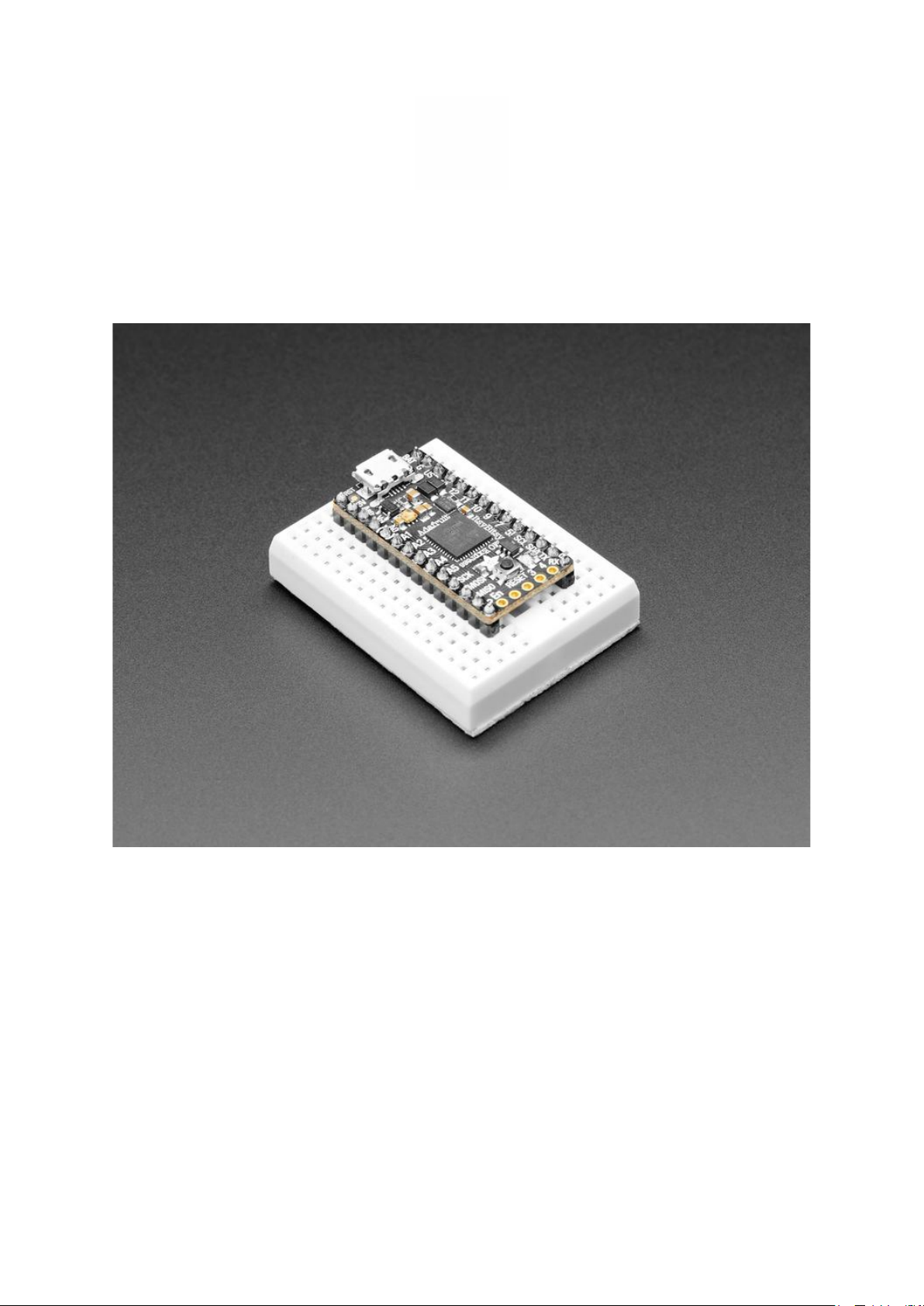
What's smaller than a Feather but larger than a Trinket? It's an Adafruit ItsyBitsy M0
Express! Small, powerful, with a rockin' ATSAMD21 Cortex M0 processor running at 48
MHz - this microcontroller board is perfect when you want something very compact,
but still with a bunch of pins.
ItsyBitsy M0 Express is only 1.4" long by 0.7" wide, but has 6 power pins, 23 digital
GPIO pins (12 of which can be analog in, 1x analog out, and 13x PWM out). It's the
same chip as the Arduino Zero(https://adafru.it/rTf) and packs much of the same
capability as an Adafruit Metro M0 Express(https://adafru.it/xoa) or Feather M0
Express(https://adafru.it/wfb) but really really small. So it's great once you've finished
up a prototype on a Metro M0 or Feather M0, and want to make the project much
smaller. It even comes with 2MB of SPI Flash built in, for data logging, file storage, or
CircuitPython code.
©Adafruit Industries Page 7 of 217
Page 8

The most exciting part of the ItsyBitsy M0 Express is that while you can use it with the
Arduino IDE, we are shipping it with CircuitPython on board. When you plug it in, it will
show up as a very small disk drive withmain.pyon it. Editmain.pywith your favorite
text editor to build your project using Python, the most popular programming
language. No installs, IDE or compiler needed, so you can use it on any computer,
even ChromeBooks or computers you can't install software on. When you're done,
unplug the Itsy' and your code will go with you.
You can also use MakeCode(https://adafru.it/C9N)'s block-based GUI coding on this
board.
©Adafruit Industries Page 8 of 217
Page 9

Here are some of the updates you can look forward to when using ItsyBitsy M0
Express:
Same size, form-factor as the ItsyBitsy 32u4, and nearly-indentical pinout as Itsy
•
Bitsy 32u4 3.3V(https://adafru.it/BjC)
ATSAMD21G18 32-bit Cortex M0+ with 256KB Flash and 32 KB RAM
•
3.3V logic, 48 MHz, 32 bit processor
•
2 MB SPI FLASH chip for storing files and CircuitPython code storage.
•
Native USB supported by every OS- can be used in Arduino or CircuitPython as
•
USB serial console, Keyboard/Mouse HID, even a little disk drive for storing
Python scripts.
Can be used withArduino IDEorCircuitPython
•
Built in red pin #13 LED
•
Built in RGB DotStar LED
•
Tons of GPIO! 23 x GPIO pins with following capabilities:
•
1 x Trueanalog output pin- can be used to play 10-bit quality audio clips
◦
13 x PWMoutputs- for servos, LEDs, etc
◦
11 x 12-bit analog inputs
◦
7 x Hardware capacitive touch sensors with no additional components
◦
required
1 x Special Vhigh output pin gives you the higher voltage from VBAT or
◦
VUSB, for driving NeoPixels, servos, and other high-current devices. Digital
5 level-shifted output for high-voltage logic level output.
Can driveNeoPixels or DotStars on any pins, with enough memory to drive
◦
8000+ pixels.DMA-NeoPixel support on the VHigh pin(https://adafru.it/
xYD)so you can drive pixels without having to spend any processor time on
it.
Native hardware SPI, I2C and Serial all available
◦
Reset button and pin
•
Power with either USB or external output (such as a battery) - it'll automatically
•
switch over
©Adafruit Industries Page 9 of 217
Page 10

Each order comes with one assembled and tested ItsyBitsy M0 Express, with header
that can be soldered in for use with a breadboard. ItsyBity M0 Express comes with
CircuitPython & example code programmed in, but you can replace the code with
Arduino if you like
So what are you waiting for? Pick up a ItsyBitsy M0 Express today and be amazed at
how easy and fast it is to get started with CircuitPython!
Pinouts
©Adafruit Industries Page 10 of 217
Page 11

Power Pins
The ItsyBitsy M0 Express has BAT G USB on the top left, right next to the micro USB
port
These pins are:
BAT - battery input for an alternative power source to USB, the voltage can only
•
be from 3.5V to 6VDC
GND - Power/data ground
•
USB - This is the same pin as the MicroUSB connector's 5V USB power pin. This
•
should be used as an output to get 5V power from the USB port. Say if you need
to power a bunch of NeoPixels or servos.
You can always put any voltage you like into BAT and the circuitry will switch between
BAT and USB dynamically for you. That means you can have a Batter backup that only
gets enabled when USB is disconnected.
If you want to add rechargeable power, a LiPoly backpack can be soldered into these
three pins that will let you have a battery that is automatically recharged whenever
USB is plugged in, then switches to LiPoly when on the go:
©Adafruit Industries Page 11 of 217
Page 12

Adafruit LiIon/LiPoly Backpack Add-On for
Pro Trinket/ItsyBitsy
If you have an ItsyBitsy or Pro Trinket you
probably know it's the perfect little size
for a portable project. This LiPoly
backpack makes it really easy to do!
Instead of wiring 2...
https://www.adafruit.com/product/2124
In addition to the three standard power pins, the ItsyBitsy M0 Express has a few more
pins available for power sourcing:
3V - this is the regulated output from the onboard regulator. You can draw
•
500mA whether powered by USB or battery.
Vhi - this is a special pin! It is a dual-Schottkey-diode connected output from BA
•
T and USB. This means this will always have the higher-of-the-two voltages, but
will always have power output. The voltage will about 5VDC when powered by
USB, but can range from 3.5-6VDC when powered from battery. It's not
regulated, but it is high-current, great for driving servos and NeoPixels.
EN - connected to the regulator enable, it will let you shut off power - when
•
running on battery only. But at least you don't have to cut a trace or wire to your
battery. This pin does not affect power when using USB
Logic pins
This is the general purpose I/O pin set for the microcontroller. All logic is 3.3V. You
can usually use 3V logic as an input to 5V, but the 3V Itsy pins should not be
connected to 5V!
Nearly all pins can do PWM output
All pins except D4 can be interrupt inputs
©Adafruit Industries Page 12 of 217
Page 13

Along the right edge
#0 / RX - GPIO #0, also receive (input) pin for Serial1. This pin can also be an
•
analog input (Analog #20) or I2S LRCLK
#1 / TX - GPIO #1, also transmit (output) pin for Serial1. This pin can also be an
•
analog input (Analog #21) or I2S bitclock
SDA and SCL - these are the I2C hardware interface pins. There's no pull up on
•
this pin by default so when using with I2C, you may need a 2.2K-10K pullup on
each to 3.3V
#5 - GPIO #5, can also do PWM output. This is a special OUTPUT-only pin, that
•
is level-shifted up to Vhi voltage, so its perfect for driving NeoPixels that want a
~5V logic level input. You can use this with our NeoPixel DMA control library to
automatically write NeoPixel data without needing any processor time(https://
adafru.it/BkV).
#7 - GPIO #7, or I2S LRCLK
•
#9 - GPIO #9, also analog input #25 and can do PWM output, or I2S data
•
channel 0
#10 - GPIO #10, can do PWM output.
•
#11 - GPIO #11, can do PWM output.
•
#12 - GPIO #12, or I2S data channel 0
•
#13 - GPIO #13, can do PWM output and is connected to the red LED next to the
•
Reset button
©Adafruit Industries Page 13 of 217
Page 14

Along the left edge
A0 - This pin is analog input A0 but is also an analog output due to having a
•
DAC (digital-to-analog converter). You can set the raw voltage to anything from 0
to 3.3V, unlike PWM outputs this is a true analog output
A1 thru A5 - These are each analog input as well as digital I/O pins. A1 and A2
•
can do PWM output.
SCK/MOSI/MISO - These are the hardware SPI pins, you can use them as
•
everyday GPIO pins but recommend keeping them free as they are best used
for hardware SPI connections for high speed.
Along the short edge:
#2 - GPIO #2
•
#3 - GPIO #3. Can also do PWM output and Analog #23, or I2S master clock
•
#4 - GPIO #4. Can also do PWM output and Analog #22, or I2S data channel 1
•
SWCLK & SWDIO - These are the debug-interface pins, used if you want to
•
reprogram the chip directly or attach a debugger.
The following pins have hardware capacitive touch capability(https://adafru.it/BkW): A
0, A1, A2, A3, A4, A5, and D9
The following pins have analog input capability: A0, A1, A2, A3, A4, A5, D0, D1, D3, D4
and D9
©Adafruit Industries Page 14 of 217
Page 15

These pins are available in CircuitPython under the board module. Names that start
with # are prefixed with D and other names are as is. So #0 / RX above is available as
board.D0 and board.RX for example.
SPI Flash and DotStar
As part of the 'Express' series of boards, this ItsyBitsy is designed for use with
CircuitPython. To make that easy, we have added two extra parts: a mini DotStar (RGB
LED) and a 2 MB SPI Flash chip
The DotStar is connected to pin #40 (clock) and #41 (data) in Arduino, so just use our
DotStar library(https://adafru.it/zbD) and set it up as a single-LED strand on pins 40 &
41. The DotStar is powered by the 3.3V power supply but that hasn't shown to make a
big difference in brightness or color. The DotStar is also used by the bootloader to let
you know if the device has enumerated correctly (green) or USB failure (red). In
CircuitPython, the LED is used to indicate the runtime status.
In CircuitPython you can access it with something like dot =
adafruit_dotstar.DotStar(board.APA102_SCK, board.APA102_MOSI, 1,
brightness=0.5)
The SPI Flash is connected to 4 pins that are not brought out on the GPIO pads. This
way you don't have to worry about the SPI flash colliding with other devices on the
main SPI connection. Under Arduino, the FLASH SCK pin is #38, MISO is #36, MOSI is
#37, and CS is #39. In Arduino, you'll be able to access the Flash SPI port under SPI1 -
©Adafruit Industries Page 15 of 217
Page 16

this is a fully new hardware SPI device separate from the GPIO pins on the outside
edge of the Feather. In CircuitPython, the SPI flash is used natively by the interpretter
and is read-only to user code, instead the Flash just shows up as the writeable disk
drive!
Other Pins
RST - this is the Reset pin, tie to ground to manually reset the microcontroller, as
•
well as launch the bootloader manually
ARef - the analog reference pin. Normally the reference voltage is the same as
•
the chip logic voltage (3.3V) but if you need an alternative analog reference,
connect it to this pin and select the external AREF in your firmware. Can't go
higher than 3.3V!
On the Itsy M4, at least for now, AREF is tied to 3.3V due to a silicon v0 bug that
does not allow the DACs to work unless AREF is connected to 3.3V. You cut the
bottom jumper if you need a different AREF voltage but note that this may
change DAC range!
Arduino IDE Setup
The first thing you will need to do is to download the latest release of the Arduino
IDE. You will need tobe using version 1.8 or higher for this guide
©Adafruit Industries Page 16 of 217
Page 17

Arduino IDE Download
https://adafru.it/f1P
After you have downloaded and installed the latest version of Arduino IDE, you will
need to start the IDEand navigate tothe Preferences menu. You can access it from
the File menu in Windows or Linux, or the Arduino menu on OS X.
A dialog will pop up just like the one shown below.
©Adafruit Industries Page 17 of 217
Page 18

We will be adding a URL to the new Additional Boards Manager URLs option. The list
of URLs is comma separated, and you will only have to add eachURL once.New
Adafruit boards and updates to existing boardswill automatically be picked upby the
Board Manager each timeit is opened. The URLs point to index files that the Board
Manager uses to build the list of available & installed boards.
To find the most up to date list of URLs you canadd, you can visit the list of third party
board URLs on the Arduino IDE wiki(https://adafru.it/f7U). We will only need to add
one URL to the IDE in this example, but you can add multiple URLS by separating
them with commas. Copy and paste the link below into theAdditional Boards
Manager URLs option in the Arduino IDE preferences.
https://adafruit.github.io/arduino-board-index/
package_adafruit_index.json
Here's a short description of each of the Adafruit supplied packages that will be
available in the Board Manager when you add the URL:
Adafruit AVR Boards - Includes support for Flora, Gemma, Feather 32u4,
•
ItsyBitsy 32u4, Trinket, & Trinket Pro.
Adafruit SAMD Boards - Includes support for Feather M0 and M4, Metro M0 and
•
M4, ItsyBitsy M0 and M4, Circuit Playground Express, Gemma M0 and Trinket
M0
Arduino Leonardo & Micro MIDI-USB - This adds MIDI over USB support for the
•
Flora, Feather 32u4, Micro and Leonardo using the arcore project(https://
adafru.it/eSI).
©Adafruit Industries Page 18 of 217
Page 19

If you have multiple boards you want to support, say ESP8266 and Adafruit, have
both URLs in the text box separated by a comma (,)
Once done click OK to save the new preference settings. Next we will look at
installing boards with the Board Manager.
Now continue to the next step to actually install the board support package!
Using with Arduino IDE
The Feather/Metro/Gemma/QTPy/Trinket M0 and M4 use an ATSAMD21 or ATSAMD51
chip, and you can pretty easily get it working with the Arduino IDE. Most libraries
(including the popular ones like NeoPixels and display) will work with the M0 and M4,
especially devices & sensors that use I2C or SPI.
Now that you have added the appropriate URLs to the Arduino IDE preferences in the
previous page, you can open the Boards Manager by navigating to the Tools->Board
menu.
Once the Board Manager opens, click on the category drop down menu on the top
left hand side of the window and select All. You will then be able to select and install
the boards suppliedby the URLs added to the preferences.
Remember you need SETUP the Arduino IDE to support our board packages see the previous page on how to add adafruit's URL to the preferences
Install SAMD Support
First up, install the latest Arduino SAMD Boards (version 1.6.11or later)
©Adafruit Industries Page 19 of 217
Page 20

You can type Arduino SAMD in the top search bar, then when you see the entry, click I
nstall
Install Adafruit SAMD
Next you can install the Adafruit SAMD package to add the board file definitions
Make sure you have Type All selected to the left of the Filter your search... box
You can type Adafruit SAMD in the top search bar, then when you see the entry, click I
nstall
Even though in theory you don't need to - I recommend rebooting the IDE
Quit and reopenthe Arduino IDE to ensure that all of the boards are properly
installed. You should now be able to select and upload to the new boards listed in the
Tools->Board menu.
©Adafruit Industries Page 20 of 217
Page 21

Select the matching board, the current options are:
Feather M0 (for use with any Feather M0 other than the Express)
•
Feather M0 Express
•
Metro M0 Express
•
Circuit Playground Express
•
Gemma M0
•
Trinket M0
•
QT Py M0
•
ItsyBitsy M0
•
Hallowing M0
•
Crickit M0 (this is for direct programming of the Crickit, which is probably not
•
what you want! For advanced hacking only)
Metro M4 Express
•
Grand Central M4 Express
•
ItsyBitsy M4 Express
•
Feather M4 Express
•
Trellis M4 Express
•
PyPortal M4
•
PyPortal M4 Titano
•
PyBadge M4 Express
•
Metro M4 Airlift Lite
•
PyGamer M4 Express
•
MONSTER M4SK
•
Hallowing M4
•
MatrixPortal M4
•
BLM Badge
•
Install Drivers (Windows 7 & 8 Only)
When you plug in the board, you'll need to possibly install a driver
©Adafruit Industries Page 21 of 217
Page 22

Click below to download our Driver Installer
Download Latest Adafruit Drivers
package
https://adafru.it/mb8
Download and run the installer
Run the installer! Since we bundle the SiLabs and FTDI drivers as well, you'll need to
click through the license
Select which drivers you want to install, the defaults will set you up with just about
every Adafruit board!
©Adafruit Industries Page 22 of 217
Page 23

Click Install to do the installin'
Blink
Now you can upload your first blink sketch!
Plug in the M0 or M4 board, and wait for it to be recognized by the OS (just takes a
few seconds). It will create a serial/COM port, you can now select it from the dropdown, it'll even be 'indicated' as Trinket/Gemma/Metro/Feather/ItsyBitsy/Trellis!
©Adafruit Industries Page 23 of 217
Page 24

Please note, the QT Py and Trellis M4 Express are two of our very few boards that
does not have an onboard pin 13 LED so you can follow this section to practice
uploading but you wont see an LED blink!
Now load up the Blink example
// the setup function runs once when you press reset or power the board
void setup() {
// initialize digital pin 13 as an output.
pinMode(13, OUTPUT);
}
// the loop function runs over and over again forever
void loop() {
digitalWrite(13, HIGH); // turn the LED on (HIGH is the voltage level)
delay(1000); // wait for a second
digitalWrite(13, LOW); // turn the LED off by making the voltage LOW
delay(1000); // wait for a second
}
And click upload! That's it, you will be able to see the LED blink rate change as you
adapt the delay() calls.
If you are having issues, make sure you selected the matching Board in the menu
that matches the hardware you have in your hand.
Successful Upload
If you have a successful upload, you'll get a bunch of red text that tells you that the
device was found and it was programmed, verified & reset
©Adafruit Industries Page 24 of 217
Page 25

After uploading, you may see a message saying "Disk NotEjectedProperly" about the
...BOOT drive. You can ignore that message: it's an artifact of how the bootloader and
uploading work.
Compilation Issues
If you get an alert that looks like
Cannot run program "{runtime.tools.arm-none-eabi-gcc.path}\bin\arm-non-eabi-g++"
Make sure you have installed the Arduino SAMD boards package, you need both Ard
uino & Adafruit SAMD board packages
©Adafruit Industries Page 25 of 217
Page 26

Manually bootloading
If you ever get in a 'weird' spot with the bootloader, or you have uploaded code that
crashes and doesn't auto-reboot into the bootloader, click the RST button twice (like a
double-click)to get back into the bootloader.
The red LED will pulse and/or RGB LED will be green, so you know that its in
bootloader mode.
Once it is in bootloader mode, you can select the newly created COM/Serial port and
re-try uploading.
You may need to go back and reselect the 'normal' USB serial port next time you want
to use the normal upload.
Ubuntu& Linux Issue Fix
Follow the steps for installing Adafruit's udev rules on this page.(https://adafru.it/iOE)
Adapting Sketches to M0 & M4
The ATSAMD21 and 51 are very nice little chips, but fairly new as Arduino-compatible
cores go. Most sketches & libraries will work but here’s a collection of things we
noticed.
The notes below cover a range of Adafruit M0 and M4 boards, but not every rule will
apply to every board (e.g. Trinket and Gemma M0 do not have ARef, so you can skip
the Analog References note!).
©Adafruit Industries Page 26 of 217
Page 27

Analog References
If you'd like to use the ARef pin for a non-3.3V analog reference, the code to use is
analogReference(AR_EXTERNAL) (it's AR_EXTERNAL not EXTERNAL)
Pin Outputs & Pullups
The old-style way of turning on a pin as an input with a pullup is to use
pinMode(pin, INPUT)
digitalWrite(pin, HIGH)
This is because the pullup-selection register on 8-bit AVR chips is the same as the
output-selection register.
For M0 & M4 boards, you can't do this anymore! Instead, use:
pinMode(pin, INPUT_PULLUP)
Code written this way still has the benefit of being backwards compatible with AVR.
You don’t need separate versions for the different board types.
Serial vs SerialUSB
99.9% of your existing Arduino sketches use Serial.print to debug and give output. For
the Official Arduino SAMD/M0 core, this goes to the Serial5 port, which isn't exposed
on the Feather. The USB port for the Official Arduino M0 core is called SerialUSB
instead.
In the Adafruit M0/M4 Core, we fixed it so that Serial goes to USB so it will
automatically work just fine.
However, on the off chance you are using the official Arduino SAMD core and not the
Adafruit version (which really, we recommend you use our version because it’s been
tuned to our boards), and you want your Serial prints and reads to use the USB port,
use SerialUSB instead of Serial in your sketch.
©Adafruit Industries Page 27 of 217
Page 28

If you have existing sketches and code and you want them to work with the M0
without a huge find-replace, put
#if defined(ARDUINO_SAMD_ZERO) && defined(SERIAL_PORT_USBVIRTUAL)
// Required for Serial on Zero based boards
#define Serial SERIAL_PORT_USBVIRTUAL
#endif
right above the first function definition in your code. For example:
AnalogWrite / PWM on Feather/Metro M0
After looking through the SAMD21 datasheet, we've found that some of the options
listed in the multiplexer table don't exist on the specific chip used in the Feather M0.
For all SAMD21 chips, there are two peripherals that can generate PWM signals: The
Timer/Counter (TC) and Timer/Counter for Control Applications (TCC). Each SAMD21
has multiple copies of each, called 'instances'.
Each TC instance has one count register, one control register, and two output
channels. Either channel can be enabled and disabled, and either channel can be
inverted. The pins connected to a TC instance can output identical versions of the
same PWM waveform, or complementary waveforms.
Each TCC instance has a single count register, but multiple compare registers and
output channels. There are options for different kinds of waveform, interleaved
switching, programmable dead time, and so on.
The biggest members of the SAMD21 family have five TC instances with two
'waveform output' (WO) channels, and three TCC instances with eight WO channels:
TC[0-4],WO[0-1]
•
©Adafruit Industries Page 28 of 217
Page 29

TCC[0-2],WO[0-7]
•
And those are the onesshown in the datasheet's multiplexer tables.
The SAMD21G used in the Feather M0 only has three TC instances with two output
channels, and three TCC instances with eightoutput channels:
TC[3-5],WO[0-1]
•
TCC[0-2],WO[0-7]
•
Tracing the signals to the pins broken out on the Feather M0, the following pins can't
do PWM at all:
Analog pin A5
•
The following pins can be configured for PWM without any signal conflicts as long as
the SPI, I2C, and UART pins keep their protocol functions:
Digital pins 5, 6, 9, 10, 11, 12, and 13
•
Analog pins A3 and A4
•
If only the SPI pins keep their protocol functions, you can also do PWM on the
following pins:
TX and SDA (Digital pins 1 and 20)
•
analogWrite() PWM range
On AVR, if you set a pin's PWM with analogWrite(pin, 255) it will turn the pin fully
HIGH. On the ARM cortex, it will set it to be 255/256 so there will be very slim but
still-existing pulses-to-0V. If you need the pin to be fully on, add test code that checks
if you are trying to analogWrite(pin, 255) and, instead, does a digitalWrite(p
in, HIGH)
©Adafruit Industries Page 29 of 217
Page 30

analogWrite() DAC on A0
If you are trying to use analogWrite() to control the DAC output on A0, make sure
you do not have a line that sets the pin to output. Remove: pinMode(A0, OUTPUT) .
Missing header files
There might be code that uses libraries that are not supported by the M0 core. For
example if you have a line with
#include <util/delay.h>
you'll get an error that says
fatal error: util/delay.h: No such file or directory
#include <util/delay.h>
^
compilation terminated.
Error compiling.
In which case you can simply locate where the line is (the error will give you the file
name and line number) and 'wrap it' with #ifdef's so it looks like:
#if !defined(ARDUINO_ARCH_SAM) && !defined(ARDUINO_ARCH_SAMD) && !
defined(ESP8266) && !defined(ARDUINO_ARCH_STM32F2)
#include <util/delay.h>
#endif
The above will also make sure that header file isn't included for other architectures
If the #include is in the arduino sketch itself, you can try just removing the line.
Bootloader Launching
For most other AVRs, clicking reset while plugged into USB will launch the bootloader
manually, the bootloader will time out after a few seconds. For the M0/M4, you'll need
to double click the button. You will see a pulsing red LED to let you know you're in
bootloader mode. Once in that mode, it wont time out! Click reset again if you want to
go back to launching code.
©Adafruit Industries Page 30 of 217
Page 31

Aligned Memory Access
This is a little less likely to happen to you but it happened to me! If you're used to 8bit platforms, you can do this nice thing where you can typecast variables around. e.g.
uint8_t mybuffer[4];
float f = (float)mybuffer;
You can't be guaranteed that this will work on a 32-bit platform because mybuffer
might not be aligned to a 2 or 4-byte boundary. The ARM Cortex-M0 can only directly
access data on 16-bit boundaries (every 2 or 4 bytes). Trying to access an oddboundary byte (on a 1 or 3 byte location) will cause a Hard Fault and stop the MCU.
Thankfully, there's an easy work around ... just use memcpy!
uint8_t mybuffer[4];
float f;
memcpy(&f, mybuffer, 4)
Floating Point Conversion
Like the AVRArduinos, the M0 library does not have full support for converting
floating point numbers to ASCII strings. Functions like sprintf will not convert floating
point. Fortunately, the standard AVR-LIBC library includes the dtostrf function which
can handle the conversion for you.
Unfortunately, the M0 run-time library does not have dtostrf. You may see some
references to using #include <avr/dtostrf.h> to get dtostrf in your code. And while it
will compile, it does not work.
Instead, check out this thread to find a working dtostrffunction you can include in
your code:
http://forum.arduino.cc/index.php?topic=368720.0(https://adafru.it/lFS)
How Much RAM Available?
The ATSAMD21G18 has 32K of RAM, but you still might need to track it for some
reason. You can do so with this handy function:
©Adafruit Industries Page 31 of 217
Page 32

extern "C" char *sbrk(int i);
int FreeRam () {
char stack_dummy = 0;
return &stack_dummy - sbrk(0);
}
Thx to http://forum.arduino.cc/index.php?topic=365830.msg2542879#msg2542879(h
ttps://adafru.it/m6D) for the tip!
Storing data in FLASH
If you're used to AVR, you've probably used PROGMEM to let the compiler know
you'd like to put a variable or string in flash memory to save on RAM. On the ARM, its
a little easier, simply add const before the variable name:
const char str[] = "My very long string";
That string is now in FLASH. You can manipulate the string just like RAM data, the
compiler will automatically read from FLASH so you dont need special progmemknowledgeable functions.
You can verify where data is stored by printing out the address:
Serial.print("Address of str $"); Serial.println((int)&str, HEX);
If the address is $2000000 or larger, its in SRAM. If the address is between $0000
and $3FFFF Then it is in FLASH
Pretty-Printing out registers
There's a lot of registers on the SAMD21, and you often are going through ASF or
another framework to get to them. So having a way to see exactly what's going on is
handy. This library from drewfish will help a ton!
https://github.com/drewfish/arduino-ZeroRegs(https://adafru.it/Bet)
©Adafruit Industries Page 32 of 217
Page 33

M4 Performance Options
As of version 1.4.0 of the Adafruit SAMD Boards package in the Arduino Boards
Manager, some options are available to wring extra performance out of M4-based
devices. These are in the Tools menu.
All of these performance tweaks involve a degree of uncertainty. There’s no
guarantee of improved performance in any given project, and some may even be
detrimental, failing to work in part or in whole. If you encounter trouble, select the
default performance settings and re-upload.
Here’s what you get and some issues you might encounter…
CPU Speed (overclocking)
This option lets you adjust the microcontroller core clock…the speed at which it
processes instructions…beyond the official datasheet specifications.
Manufacturers often rate speeds conservatively because such devices are marketed
for harsh industrial environments…if a system crashes, someone could lose a limb or
worse. But most creative tasks are less critical and operate in more comfortable
settings, and we can push things a bit if we want more speed.
There is a small but nonzero chance of code locking up or failing to run entirely. If this
happens, try dialing back the speed by one notch and re-upload, see if it’s more
stable.
Much more likely, some code or libraries may not play well with the nonstandard CPU
speed. For example, currently the NeoPixel library assumes a 120 MHz CPU speed
and won’t issue the correct data at other settings (this will be worked on). Other
©Adafruit Industries Page 33 of 217
Page 34

libraries may exhibit similar problems, usually anything that strictly depends on CPU
timing…you might encounter problems with audio- or servo-related code depending
how it’s written. If you encounter such code or libraries, set the CPU speed to the
default 120 MHz and re-upload.
Optimize
There’s usually more than one way to solve a problem, some more resource-intensive
than others. Since Arduino got its start on resource-limited AVR microcontrollers, the
C++ compiler has always aimed for the smallest compiled program size. The
“Optimize” menu gives some choices for the compiler to take different and often
faster approaches, at the expense of slightly larger program size…with the huge flash
memory capacity of M4 devices, that’s rarely a problem now.
The “Small” setting will compile your code like it always has in the past, aiming for the
smallest compiled program size.
The “Fast” setting invokes various speed optimizations. The resulting program should
produce the same results, is slightly larger, and usually (but not always) noticably
faster. It’s worth a shot!
“Here be dragons” invokes some more intensive optimizations…code will be larger
still, faster still, but there’s a possibility these optimizations could cause unexpected
behaviors. Some code may not work the same as before. Hence the name. Maybe
you’ll discover treasure here, or maybe you’ll sail right off the edge of the world.
Most code and libraries will continue to function regardless of the optimizer settings.
If you do encounter problems, dial it back one notch and re-upload.
Cache
This option allows a small collection of instructions and data to be accessed more
quickly than from flash memory, boosting performance. It’s enabled by default and
should work fine with all code and libraries. But if you encounter some esoteric
situation, the cache can be disabled, then recompile and upload.
Max SPI and Max QSPI
These should probably be left at their defaults. They’re present mostly for our own
experiments and can cause serious headaches.
©Adafruit Industries Page 34 of 217
Page 35

Max SPI determines the clock source for the M4’s SPI peripherals. Under normal
circumstances this allows transfers up to 24 MHz, and should usually be left at that
setting. But…if you’re using write-only SPI devices (such as TFT or OLED displays), this
option lets you drive them faster (we’ve successfully used 60 MHz with some TFT
screens). The caveat is, if using any read/write devices (such as an SD card), this will
not work at all…SPI readsabsolutely max out at the default 24 MHz setting, and
anything else will fail. Write = OK. Read = FAIL. This is true even if your code is using a
lower bitrate setting…just having the different clock source prevents SPI reads.
Max QSPI does similarly for the extra flash storage on M4 “Express” boards. Very few
Arduino sketches access this storage at all, let alone in a bandwidth-constrained
context, so this will benefit next to nobody. Additionally, due to the way clock dividers
are selected, this will only provide some benefit when certain “CPU Speed” settings
are active. Our PyPortal Animated GIF Display(https://adafru.it/EkO) runs marginally
better with it, if using the QSPI flash.
Enabling the Buck Converter on some M4 Boards
If you want to reduce power draw, some of our boards have an inductor so you can
use the 1.8V buck converter instead of the built in linear regulator. If the board does
have an inductor (see the schematic) you can add the line SUPC->VREG.bit.SEL =
1; to your code to switch to it. Note it will make ADC/DAC reads a bit noisier so we
don't use it by default. You'll save ~4mA(https://adafru.it/F0H).
Using SPI Flash
One of the bestfeatures of the M0 express board is a small SPI flash memory chip
built into the board. This memory can be used for almost any purpose like
storingdata files, Python code, and more. Think of it like a little SD card that is always
connected to the board, and in fact with Arduino you can access the memory using a
library that is very similar to the Arduino SD card library(https://adafru.it/ucu). You can
even read and write files that CircuitPython stores on the flash chip!
To use the flash memory with Arduino you'll need to install the Adafruit SPI Flash
Memory library(https://adafru.it/wbt) in the Arduino IDE.
Open up the Arduino library manager
©Adafruit Industries Page 35 of 217
Page 36

Search for theAdafruit SPIFlashlibrary and install it
Search for the SdFat - Adafruit Forklibrary and install it
We also have a great tutorial on Arduino library installation at:
http://learn.adafruit.com/adafruit-all-about-arduino-libraries-install-use(https://
adafru.it/aYM)
Once the library is installed look for the following examples in the library:
fatfs_circuitpython
•
fatfs_datalogging
•
fatfs_format
•
fatfs_full_usage
•
fatfs_print_file
•
flash_erase
•
These examples allow you to format the flash memory with a FAT filesystem (the same
kind of filesystem used on SD cards) and read and write files to it just like a SD card.
©Adafruit Industries Page 36 of 217
Page 37

Read & Write CircuitPython Files
The fatfs_circuitpython example shows how to read and write files on the flash chip
so that they're accessible from CircuitPython. This means you can run a CircuitPython
program on your board and have it store data, then run an Arduino sketch that uses
this library to interact with the same data.
Note that before you use the fatfs_circuitpython example you must have loaded
CircuitPython on your board. Load the latest version of CircuitPython as explained in
this guide(https://adafru.it/BeN) first to ensure a CircuitPython filesystem is initialized
and written to the flash chip. Once you've loaded CircuitPython then you can run the
fatfs_circuitpython example sketch.
To run the sketch load it in the Arduino IDE and upload it to the Feather/Metro/
ItsyBitsy M0 board. Then open the serial monitor at 115200 baud. You should see the
serial monitor display messages as it attempts to read files and write to a file on the
flash chip. Specifically the example will look for a boot.py and main.py file (like what
CircuitPython runs when it starts) and print out their contents. Then it will add a line
to the end of a data.txt file on the board (creating it if it doesn't exist already). After
running the sketch you canreload CircuitPython on the board and open the data.txt
file to read itfrom CircuitPython!
To understand how to read & write files that are compatible with CircuitPython let's
examine the sketch code. First notice an instance of the Adafruit_M0_Express_Circu
itPython class is created and passed an instance of the flash chip class in the last line
below:
#define FLASH_SS SS1 // Flash chip SS pin.
#define FLASH_SPI_PORT SPI1 // What SPI port is Flash on?
Adafruit_SPIFlash flash(FLASH_SS, &FLASH_SPI_PORT); // Use hardware SPI
// Alternatively you can define and use non-SPI pins!
//Adafruit_SPIFlash flash(SCK1, MISO1, MOSI1, FLASH_SS);
// Finally create an Adafruit_M0_Express_CircuitPython object which gives
// an SD card-like interface to interacting with files stored in CircuitPython's
// flash filesystem.
Adafruit_M0_Express_CircuitPython pythonfs(flash);
By using this Adafruit_M0_Express_CircuitPython class you'll get a filesystem object
that is compatible with reading and writing files on a CircuitPython-formatted flash
chip. This is very important for interoperability between CircuitPython and Arduino as
CircuitPython has specialized partitioning and flash memory layoutthat isn't
compatible with simpler uses of the library (shown in the other examples).
©Adafruit Industries Page 37 of 217
Page 38

Once an instance of the Adafruit_M0_Express_CircuitPython class is created (called p
ythonfs in this sketch) you can go on to interact with it just like if it were the SD card
library in Arduino(https://adafru.it/wbw). You can open files for reading & writing,
create directories, delete files and directories and more. Here's how the sketch
checks if a boot.py file exists and prints it out a character at a time:
// Check if a boot.py exists and print it out.
if (pythonfs.exists("boot.py")) {
File bootPy = pythonfs.open("boot.py", FILE_READ);
Serial.println("Printing boot.py...");
while (bootPy.available()) {
char c = bootPy.read();
Serial.print(c);
}
Serial.println();
}
else {
Serial.println("No boot.py found...");
}
Notice the exists function is called to check if the boot.py file is found, and then the o
pen function is used to open it in read mode. Once a file is opened you'll get a
reference to a File class object which you can read and write from as if it were a Serial
device (again just like the SD card library, all of the same File classfunctions are
available(https://adafru.it/wbw)). In this case the available function will return the
number of bytes left to read in the file, and the read function will read a character at a
time to print it to the serial monitor.
Writing a file is just as easy, here's how the sketch writes to data.txt:
// Create or append to a data.txt file and add a new line
// to the end of it. CircuitPython code can later open and
// see this file too!
File data = pythonfs.open("data.txt", FILE_WRITE);
if (data) {
// Write a new line to the file:
data.println("Hello CircuitPython from Arduino!");
data.close();
// See the other fatfs examples like fatfs_full_usage and fatfs_datalogging
// for more examples of interacting with files.
Serial.println("Wrote a new line to the end of data.txt!");
}
else {
Serial.println("Error, failed to open data file for writing!");
}
Again the open function is used but this time it's told to open the file for writing. In
this mode the file will be opened for appending (i.e. data added to the end of it) if it
exists, or it will be created if it doesn't exist. Once the file is open print functions like
print and println can be used to write data to the file ( just like writing to the serial
monitor). Be sure to close the file when finished writing!
©Adafruit Industries Page 38 of 217
Page 39

That's all there is to basic file reading and writing. Check out the fatfs_full_usage
example for examples of even more functions like creating directories, deleting files &
directories, checking the size of files, and more! Remember though to interact with
CircuitPython files you need to use the Adafruit_Feather_M0_CircuitPython class as
shown in the fatfs_circuitpython example above!
Format Flash Memory
The fatfs_format example will format the SPI flash with a new blank filesystem. Be
warned this sketch will delete all data on the flash memory, including any Python code
or other data you might have stored! The format sketch is useful if you'd like to wipe
everything away and start fresh, or to help get back in agood state if the memory
should get corrupted for some reason.
Be aware too the fatfs_format and examples below are not compatible with a
CircuitPython-formatted flash chip! If you need to share data between Arduino &
CircuitPython check out the fatfs_circuitpython example above.
To run the format sketch load it in the Arduino IDE and upload it to the M0 board.
Then open the serial monitor at 115200 baud. You should see the serial monitor
display a message asking you to confirmformatting the flash. If you don't see this
message then close the serial monitor, press the board's reset button, and open the
serial monitor again.
Type OK and press enter in the serial monitor input to confirm that you'd like to format
the flash memory. You need to enter OK in all capital letters!
Once confirmed the sketch will format the flash memory. The format process takes
about a minute so be patient as the data is erased and formatted. You should see a
©Adafruit Industries Page 39 of 217
Page 40

message printed once the format process is complete. At this point the flash chip will
beready to use with a brand new empty filesystem.
Datalogging Example
One handy use of the SPI flash is to store data, like datalogging sensor readings. The
fatfs_datalogging example shows basic file writing/datalogging. Open the example in
the Arduino IDE and upload it to your Feather M0 board. Then open the serial
monitor at 115200 baud. You should see a message printed every minute as the
sketch writes a new line of data to a file on the flash filesystem.
To understand how to write to a file look in the loop function of the sketch:
// Open the datalogging file for writing. The FILE_WRITE mode will open
// the file for appending, i.e. it will add new data to the end of the file.
File dataFile = fatfs.open(FILE_NAME, FILE_WRITE);
// Check that the file opened successfully and write a line to it.
if (dataFile) {
// Take a new data reading from a sensor, etc. For this example just
// make up a random number.
int reading = random(0,100);
// Write a line to the file. You can use all the same print functions
// as if you're writing to the serial monitor. For example to write
// two CSV (commas separated) values:
dataFile.print("Sensor #1");
dataFile.print(",");
dataFile.print(reading, DEC);
dataFile.println();
// Finally close the file when done writing. This is smart to do to make
// sure all the data is written to the file.
dataFile.close();
Serial.println("Wrote new measurement to data file!");
}
Just like using the Arduino SD card library you create a File object by calling an open
function and pointing it at the name of the file and how you'd like to open it (FILE_WR
ITE mode, i.e. writing new data to the end of the file). Notice however instead of
calling open on a global SD card object you're calling it on a fatfs object created
earlier in the sketch (look at the top after the #define configuration values).
Once the file is opened it's simply a matter of calling print and println functions on the
file object to write data inside of it. This is just like writing data to the serial monitor
and you can print out text, numeric, and other types of data. Be sure to close the file
when you're done writing to ensure the data is stored correctly!
©Adafruit Industries Page 40 of 217
Page 41

Reading and Printing Files
The fatfs_print_file example will open a file (by default the data.csv file created by
running the fatfs_datalogging example above) and print all of its contents to the serial
monitor. Open the fatfs_print_file example and load it on your Feather M0 board,
then open the serial monitor at 115200 baud. You should see the sketch print out the
contents of data.csv (if you don't have a file called data.csv on the flash look at
running the datalogging example above first).
To understand how to read data from a file look in the setupfunction of the sketch:
// Open the file for reading and check that it was successfully opened.
// The FILE_READ mode will open the file for reading.
File dataFile = fatfs.open(FILE_NAME, FILE_READ);
if (dataFile) {
// File was opened, now print out data character by character until at the
// end of the file.
Serial.println("Opened file, printing contents below:");
while (dataFile.available()) {
// Use the read function to read the next character.
// You can alternatively use other functions like readUntil, readString, etc.
// See the fatfs_full_usage example for more details.
char c = dataFile.read();
Serial.print(c);
}
}
Just like when writing data with the datalogging example you create a File object by
calling the open function on a fatfs object. This time however you pass a file mode of
FILE_READ which tells the filesystemyou want to read data.
After you open a file for reading you can easily check if data is available by calling the
available function on the file, and then read a single character with the read function.
This makes it easy to loop through all of the data in a file by checking if it's available
and reading a character at a time. However there are more advanced read functions
you can use too--see the fatfs_full_usage example or even the Arduino SD library
documentation(https://adafru.it/ucu) (the SPI flash library implements the same
functions).
Full Usage Example
For a more complete demonstration of reading and writing files look at the fatfs_full_
usage example. This examples uses every function in the library and demonstrates
things like checking for the existence of a file, creating directories, deleting files,
deleting directories,and more.
©Adafruit Industries Page 41 of 217
Page 42

Remember the SPI flash library is built to have the same functions and interface as the
Arduino SD library(https://adafru.it/ucu) so if you have code or examples that store
data on a SD card they should be easy to adapt to use the SPI flash library, just create
a fatfs object like in the examples above and use its open function instead of the
global SD object's open function. Once you have a reference to a file all of the
functions and usage should be the same between the SPI flash and SD libraries!
Accessing SPI Flash
Arduino doesn't have the ability to show up as a 'mass storage' disk drive. So instead
we must use CircuitPython to do that part for us. Here's the full technique:
Start the bootloader on the Express board. Drag over the latest circuitpython uf2
•
file
After a moment, you should see a CIRCUITPY drive appear on your hard drive
•
with boot_out.txt on it
Now go to Arduino and upload the fatfs_circuitpython example sketch from the
•
Adafruit SPI library. Open the serial console. It will successfully mount the
filesystem and write a new line to data.txt
Back on your computer, re-start the Express board bootloader, and re-drag circu
•
itpython.uf2 onto the BOOT drive to reinstall circuitpython
Check the CIRCUITPY drive, you should now see data.txt which you can open to
•
read!
©Adafruit Industries Page 42 of 217
Page 43

Once you have your Arduino sketch working well, for datalogging, you can simplify
this procedure by dragging CURRENT.UF2 off of the BOOT drive to make a backup of
the current program before loading circuitpython on. Then once you've accessed the
file you want, re-drag CURRENT.UF2 back onto the BOOT drive to re-install the
Arduino sketch!
Feather HELP!
Even though this FAQ is labeled for Feather, the questions apply to ItsyBitsy's as
well!
My ItsyBitsy/Feather stopped working when I unplugged the USB!
A lot of our example sketches have a
while (!Serial);
line in setup(), to keep the board waiting until the USB is opened. This makes it a
lot easier to debug a program because you get to see all the USB data output. If
you want to run your Feather without USB connectivity, delete or comment out that
line
©Adafruit Industries Page 43 of 217
Page 44

My Feather never shows up as a COM or Serial port in the Arduino IDE
A vast number of Itsy/Feather 'failures' are due to charge-only USB cables
We get upwards of 5 complaints a day that turn out to be due to charge-only
cables!
Use only a cable that you know is for data syncing
If you have any charge-only cables, cut them in half throw them out. We are
serious! They tend to be low quality in general, and will only confuse you and
others later, just get a good data+charge USB cable.
A quality USB port is critical. Avoid plugging into USB keyboards and when
possible use a USB-2 HUB to avoid USB3 issues.
Ack! I "did something" and now when I plug in the Itsy/ Feather, it doesn't show up as a device anymore so I cant upload to it or fix it...
No problem! You can 'repair' a bad code upload easily. Note that this can happen if
you set a watchdog timer or sleep mode that stops USB, or any sketch that
'crashes' your board
Turn on verbose upload in the Arduino IDE preferences
1.
Plug in Itsy or Feather 32u4/M0, it won't show up as a COM/serial port that's
2.
ok
Open up the Blink example (Examples->Basics->Blink)
3.
Select the correct board in the Tools menu, e.g. Feather 32u4, Feather M0,
4.
Itsy 32u4 or M0 (physically check your board to make sure you have the right
one selected!)
Compile it (make sure that works)
5.
Click Upload to attempt to upload the code
6.
The IDE will print out a bunch of COM Ports as it tries to upload. During this
7.
time, double-click the reset button, you'll see the red pulsing LED that tells
you its now in bootloading mode
The board will show up as the Bootloader COM/Serial port
8.
The IDE should see the bootloader COM/Serial port and upload properly
9.
©Adafruit Industries Page 44 of 217
Page 45

I can't get the Itsy/Feather USB device to show up - I get "USB Device Malfunctioning" errors!
This seems to happen when people select the wrong board from the Arduino
Boards menu.
If you have a Feather 32u4 (look on the board to read what it is you have) Make
sure you select Feather 32u4 for ATMega32u4 based boards! Do not use anything
else, do not use the 32u4 breakout board line.
If you have a Feather M0 (look on the board to read what it is you have) Make sure
you select Feather M0 - do not use 32u4 or Arduino Zero
If you have a ItsyBitsy M0 (look on the board to read what it is you have) Make sure
you select ItsyBitsy M0 - do not use 32u4 or Arduino Zero
©Adafruit Industries Page 45 of 217
Page 46

I'm having problems with COM ports and my Itsy/Feather 32u4/M0
Theres two COM ports you can have with the 32u4/M0, one is the user port and
one is the bootloader port. They are not the same COM port number!
When you upload a new user program it will come up with a user com port,
particularly if you use Serial in your user program.
If you crash your user program, or have a program that halts or otherwise fails, the
user COM port can disappear.
When the user COM port disappears, Arduino will not be able to automatically start
the bootloader and upload new software.
So you will need to help it by performing the click-during upload procedure to restart the bootloader, and upload something that is known working like "Blink"
I don't understand why the COM port disappears, this does not happen on my Arduino UNO!
UNO-type Arduinos have a seperate serial port chip (aka "FTDI chip" or "Prolific
PL2303" etc etc) which handles all serial port capability seperately than the main
chip. This way if the main chip fails, you can always use the COM port.
M0 and 32u4-based Arduinos do not have a seperate chip, instead the main
processor performs this task for you. It allows for a lower cost, higher power
setup...but requires a little more effort since you will need to 'kick' into the
bootloader manually once in a while
I'm trying to upload to my 32u4, getting "avrdude: butterfly_recv(): programmer is not responding" errors
This is likely because the bootloader is not kicking in and you are accidentally
trying to upload to the wrong COM port
The best solution is what is detailed above: manually upload Blink or a similar
working sketch by hand by manually launching the bootloader
©Adafruit Industries Page 46 of 217
Page 47

I'm trying to upload to my Feather M0, and I get this error "Connecting to programmer: .avrdude: butterfly_recv(): programmer is not responding"
You probably don't have Feather M0 selected in the boards drop-down. Make sure
you selected Feather M0.
I'm trying to upload to my Feather and i get this error "avrdude: ser_recv(): programmer is not responding"
You probably don't have Feather M0 / Feather 32u4 selected in the boards dropdown. Make sure you selected Feather M0 (or Feather 32u4).
I attached some wings to my Feather and now I can't read the battery voltage!
Make sure your Wing doesn't use pin #9 which is the analog sense for the lipo
battery!
The yellow LED Is flickering on my Feather, but no battery is plugged in, why is that?
The charge LED is automatically driven by the Lipoly charger circuit. It will try to
detect a battery and is expecting one to be attached. If there isn't one it may flicker
once in a while when you use power because it's trying to charge a (non-existant)
battery.
It's not harmful, and its totally normal!
The Arduino IDE gives me "Device Descriptor Request Failed"
This can require "manual bootloading".
If you ever get in a 'weird' spot with the bootloader, or you have uploaded code that
crashes and doesn't auto-reboot into the bootloader, double-click the RST button to
get back into the bootloader. The red LED will pulse, so you know that its in
bootloader mode. Do the reset button double-press right as the Arduino IDE says its
attempting to upload the sketch, when you see the Yellow Arrow lit and the Uploadin
g... text in the status bar.
©Adafruit Industries Page 47 of 217
Page 48

ttps://adafru.it/UJA)
Don't click the reset button before uploading, unlike other bootloaders you want this
one to run at the time Arduino is trying to upload
What is CircuitPython?
CircuitPython is a programming language designed to simplify experimenting and
learning to program on low-cost microcontroller boards. It makes getting started
easier than ever with no upfront desktop downloads needed. Once you get your
board set up, open any text editor, and get started editing code. It's that simple.
(h
©Adafruit Industries Page 48 of 217
Page 49

CircuitPython is based on Python
Python is the fastest growing programming language. It's taught in schools and
universities. It's a high-level programming language which means it's designed to be
easier to read, write and maintain. It supports modules and packages which means it's
easy to reuse your code for other projects. It has a built in interpreter which means
there are no extra steps, like compiling, to get your code to work. And of course,
Python is Open Source Software which means it's free for anyone to use, modify or
improve upon.
CircuitPython adds hardware support to all of these amazing features. If you already
have Python knowledge, you can easily apply that to using CircuitPython. If you have
no previous experience, it's really simple to get started!
Why would I use CircuitPython?
CircuitPython is designed to run on microcontroller boards. A microcontroller board is
a board with a microcontroller chip that's essentially an itty-bitty all-in-one computer.
The board you're holding is a microcontroller board! CircuitPython is easy to use
because all you need is that little board, a USB cable, and a computer with a USB
connection. But that's only the beginning.
Other reasons to use CircuitPython include:
You want to get up and running quickly. Create a file, edit your code, save the
•
file, and it runs immediately. There is no compiling, no downloading and no
uploading needed.
You're new to programming. CircuitPython is designed with education in mind.
•
It's easy to start learning how to program and you get immediate feedback from
the board.
©Adafruit Industries Page 49 of 217
Page 50

Easily update your code. Since your code lives on the disk drive, you can edit it
•
whenever you like, you can also keep multiple files around for easy
experimentation.
The serial console and REPL. These allow for live feedback from your code and
•
interactive programming.
File storage. The internal storage for CircuitPython makes it great for data-
•
logging, playing audio clips, and otherwise interacting with files.
Strong hardware support. There are many libraries and drivers for sensors,
•
breakout boards and other external components.
It's Python! Python is the fastest-growing programming language. It's taught in
•
schools and universities. CircuitPython is almost-completely compatible with
Python. It simply adds hardware support.
This is just the beginning. CircuitPython continues to evolve, and is constantly being
updated. Adafruit welcomes and encourages feedback from the community, and
incorporate it into the development of CircuitPython. That's the core of the open
source concept. This makes CircuitPython better for you and everyone who uses it!
CircuitPython
CircuitPython(https://adafru.it/tB7) is a derivative of MicroPython(https://adafru.it/BeZ)
designed to simplify experimentation and education on low-cost microcontrollers. It
makes it easier than ever to get prototyping by requiring no upfront desktop software
downloads. Simply copy and edit files on the CIRCUITPY drive to iterate.
The following instructions will show you how to install CircuitPython. If you've already
installed CircuitPython but are looking to update it or reinstall it, the same steps work
for that as well!
Set up CircuitPython Quick Start!
Follow this quick step-by-step for super-fast Python power :)
Download the latest version of
CircuitPython for this board via
CircuitPython.org
https://adafru.it/Emi
©Adafruit Industries Page 50 of 217
Page 51

Click the link above and download the
latest UF2 file.
Download and save it to your desktop (or
wherever is handy).
Plug your ItsyBitsy M0 into your computer using a known-good USB cable.
A lot of people end up using charge-only USB cables and it is very frustrating! So
make sure you have a USB cable you know is good for data sync.
Double-click the Reset button next to the USB connector on your board, and you will
see the DotStar RGB LED turn green. If it turns red, check the USB cable, try another
USB port, etc. Note: The little red LED next to the USB connector will pulse red. That's
ok!
If double-clicking doesn't work the first time, try again. Sometimes it can take a few
tries to get the rhythm right!
©Adafruit Industries Page 51 of 217
Page 52

You will see a new disk drive appear
called ITSYBOOT.
Drag the adafruit_circuitpython_etc.uf2
file to ITSYBOOT.
The LED will flash. Then, the ITSYBOOT
drive will disappear and a new disk drive
called CIRCUITPY will appear.
That's it, you're done! :)
Further Information
For more detailed info on installing CircuitPython, check out Installing CircuitPython(h
ttps://adafru.it/Amd).
©Adafruit Industries Page 52 of 217
Page 53

Installing the Mu Editor
Mu is a simple code editor that works with the Adafruit CircuitPython boards. It's
written in Python and works on Windows, MacOS, Linux and Raspberry Pi. The serial
console is built right in so you get immediate feedback from your board's serial
output!
Mu is our recommended editor - please use it (unless you are an experienced
coder with a favorite editor already!).
Download and Install Mu
Download Mu fromhttps://
codewith.mu(https://adafru.it/Be6).
Click theDownload link for downloads
and installation instructions.
Click Start Hereto find a wealth of other
information, including extensive tutorials
and and how-to's.
Windows users: due to the nature of MSI installers, please remove old versions of
Mu before installing the latest version.
©Adafruit Industries Page 53 of 217
Page 54

Starting Up Mu
The first time you start Mu, you will be
prompted to select your 'mode' - you can
always change your mind later. For now
please select CircuitPython!
The current mode is displayed in the
lower right corner of the window, next to
the "gear" icon. If the mode says
"Microbit" or something else, click the
Mode button in the upper left, and then
choose "CircuitPython" in the dialog box
that appears.
Mu attempts to auto-detect your board
on startup, so if you do not have a
CircuitPython board plugged in with a
CIRCUITPY drive available, Mu will inform
you where it will store any code you save
until you plug in a board.
To avoid this warning, plug in a board
and ensure that the CIRCUITPY drive is
mounted before starting Mu.
Using Mu
You can now explore Mu! The three main sections of the window are labeled below;
the button bar, the text editor, and the serial console / REPL.
©Adafruit Industries Page 54 of 217
Page 55

Now you're ready to code! Let's keep going...
Creating and Editing Code
One of the best things about CircuitPython is how simple it is to get code up and
running. This section covers how to create and edit your first CircuitPython program.
To create and edit code, all you'll need is an editor. There are many options. Adafruit
strongly recommends using Mu! It's designed for CircuitPython, and it's really simple
and easy to use, with a built in serial console!
If you don't or can't use Mu, there are a number of other editors that work quite well.
The Recommended Editors page(https://adafru.it/Vue) has more details. Otherwise,
make sure you do "Eject" or "Safe Remove" on Windows or "sync" on Linux after
writing a file if you aren't using Mu. (This is not a problem on MacOS.)
©Adafruit Industries Page 55 of 217
Page 56

Creating Code
Installing CircuitPython generates a
code.py file on your CIRCUITPY drive. To
begin your own program, open your
editor, and load the code.py file from the
CIRCUITPY drive.
If you are using Mu, click the Load button
in the button bar, navigate to the
CIRCUITPY drive, and choose code.py.
Copy and paste the following code into your editor:
import board
import digitalio
import time
led = digitalio.DigitalInOut(board.LED)
led.direction = digitalio.Direction.OUTPUT
while True:
led.value = True
time.sleep(0.5)
led.value = False
time.sleep(0.5)
The KB2040, QT Py and the Trinkeys do not have a built-in little red LED! There is
an addressable RGB NeoPixel LED. The above example will NOT work on the
KB2040, QT Py or the Trinkeys!
If you're using a KB2040, QT Py or a Trinkey, please download the NeoPixel blink
example(https://adafru.it/UDU).
The NeoPixel blink example uses the onboard NeoPixel, but the time code is the
same. You can use the linked NeoPixel Blink example to follow along with this
guide page.
©Adafruit Industries Page 56 of 217
Page 57

It will look like this. Note that under the
while True: line, the next four lines
begin with four spaces to indent them,
and they're indented exactly the same
amount. All the lines before that have no
spaces before the text.
Save the code.py file on your CIRCUITPY
drive.
The little LED should now be blinking. Once per half-second.
Congratulations, you've just run your first CircuitPython program!
On most boards you'll find a tiny red LED.
On the ItsyBitsy nRF52840, you'll find a tiny blue LED.
On QT Py M0, QT Py RP2040, and the Trinkey series, you will find only an RGB
NeoPixel LED.
©Adafruit Industries Page 57 of 217
Page 58

Editing Code
To edit code, open thecode.pyfile on
your CIRCUITPY drive into your editor.
Make the desired changes to your code.
Save the file. That's it!
Your code changes are run as soon as the file is done saving.
There's one warning before you continue...
Don't click reset or unplug your board!
The CircuitPython code on your board detects when the files are changed or written
and will automatically re-start your code. This makes coding very fast because you
save, and it re-runs. If you unplug or reset the board before your computer finishes
writing the file to your board, you can corrupt the drive. If this happens, you may lose
the code you've written, so it's important to backup your code to your computer
regularly.
There are a couple of ways to avoid filesystem corruption.
1. Use an editor that writes out the file completely when you save it.
Check out the Recommended Editors page(https://adafru.it/Vue) for details on
different editing options.
If you are dragging a file from your host computer onto the CIRCUITPY drive, you
still need to do step 2. Eject or Sync (below) to make sure the file is completely
written.
©Adafruit Industries Page 58 of 217
Page 59

2. Eject or Sync the Drive After Writing
If you are using one of our not-recommended-editors, not all is lost! You can still make
it work.
On Windows, you can Eject or Safe Remove the CIRCUITPY drive. It won't actually
eject, but it will force the operating system to save your file to disk. On Linux, use the
sync command in a terminal to force the write to disk.
You also need to do this if you use Windows Explorer or a Linux graphical file
manager to drag a file onto CIRCUITPY.
Oh No I Did Something Wrong and Now The CIRCUITPY Drive Doesn't Show Up!!!
Don't worry! Corrupting the drive isn't the end of the world (or your board!). If this
happens, follow the steps found on the Troubleshooting(https://adafru.it/Den) page
of every board guide to get your board up and running again.
Back to Editing Code...
Now! Let's try editing the program you added to your board. Open your code.py file
into your editor. You'll make a simple change. Change the first 0.5 to 0.1 . The code
should look like this:
import board
import digitalio
import time
led = digitalio.DigitalInOut(board.LED)
led.direction = digitalio.Direction.OUTPUT
while True:
led.value = True
time.sleep(0.1)
led.value = False
time.sleep(0.5)
Leave the rest of the code as-is. Save your file. See what happens to the LED on your
board? Something changed! Do you know why?
You don't have to stop there! Let's keep going. Change the second 0.5 to 0.1 so it
looks like this:
©Adafruit Industries Page 59 of 217
Page 60

while True:
led.value = True
time.sleep(0.1)
led.value = False
time.sleep(0.1)
Now it blinks really fast! You decreased the both time that the code leaves the LED on
and off!
Now try increasing both of the 0.1 to 1 . Your LED will blink much more slowly
because you've increased the amount of time that the LED is turned on and off.
Well done! You're doing great! You're ready to start into new examples and edit them
to see what happens! These were simple changes, but major changes are done using
the same process. Make your desired change, save it, and get the results. That's
really all there is to it!
Naming Your Program File
CircuitPython looks for a code file on the board to run. There are four options: code.t
xt, code.py, main.txt and main.py. CircuitPython looks for those files, in that order, and
then runs the first one it finds. While code.py is the recommended name for your code
file, it is important to know that the other options exist. If your program doesn't seem
to be updating as you work, make sure you haven't created another code file that's
being read instead of the one you're working on.
Connecting to the Serial Console
One of the staples of CircuitPython (and programming in general!) is something called
a "print statement". This is a line you include in your code that causes your code to
output text. A print statement in CircuitPython (and Python) looks like this:
print("Hello, world!")
This line in your code.py would result in:
Hello, world!
However, these print statements need somewhere to display. That's where the serial
console comes in!
©Adafruit Industries Page 60 of 217
Page 61

The serial console receives output from your CircuitPython board sent over USB and
displays it so you can see it. This is necessary when you've included a print statement
in your code and you'd like to see what you printed. It is also helpful for
troubleshooting errors, because your board will send errors and the serial console will
display those too.
The serial console requires an editor that has a built in terminal, or a separate
terminal program. A terminal is a program that gives you a text-based interface to
perform various tasks.
Are you using Mu?
If so, good news! The serial consoleis built into Mu and willautodetect your board
making using the serial console really really easy.
First, make sure your CircuitPython board
is plugged in.
If you open Mu without a board plugged
in, you may encounter the error seen
here, letting you know no CircuitPython
board was found and indicating where
your code will be stored until you plug in
a board.
If you are using Windows 7, make sure
you installed the drivers(https://adafru.it/
VuB).
Once you've opened Mu with your board plugged in, look for the Serial button in the
button bar and click it.
The Mu window will split in two, horizontally, and display the serial console at the
bottom.
©Adafruit Industries Page 61 of 217
Page 62

If nothing appears in the serial console, it may mean your code is done running
or has no print statements in it. Click into the serial console part of Mu, and press
CTRL+D to reload.
Serial Console Issues or Delays on Linux
If you're on Linux, and are seeing multi-second delays connecting to the serial
console, or are seeing "AT" and other gibberish when you connect, then the modemma
nager service might be interfering. Just remove it; it doesn't have much use unless
you're still using dial-up modems.
To remove modemmanager , type the following command at a shell:
sudo apt purge modemmanager
Setting Permissions on Linux
On Linux, if you see an error box something like the one below when you press the S
erial button, you need to add yourself to a user group to have permission to connect
to the serial console.
On Ubuntu and Debian, add yourself to the dialout group by doing:
sudo adduser $USER dialout
After running the command above, reboot your machine to gain access to the group.
On other Linux distributions, the group you need may be different. See the Advanced
©Adafruit Industries Page 62 of 217
Page 63

Serial Console on Linux(https://adafru.it/VAO)for details on how to add yourself to
the right group.
Using Something Else?
If you're not using Mu to edit, are using or if for some reason you are not a fan of its
built in serial console, you can run the serial console from a separate program.
Windows requires you to download a terminal program. Check out the Advanced
Serial Console on Windows page for more details.(https://adafru.it/AAH)
MacOS has Terminal built in, though there are other options available for download. C
heck the Advanced Serial Console on Mac page for more details.(https://adafru.it/
AAI)
Linux has a terminal program built in, though other options are available for
download. Check the Advanced Serial Console on Linux page for more details.(https:
//adafru.it/VAO)
Once connected, you'll see something like the following.
Interacting with the Serial Console
Once you've successfully connected to the serial console, it's time to start using it.
The code you wrote earlier has no output to the serial console. So, you're going to
edit it to create some output.
Open your code.py file into your editor, and include a print statement. You can print
anything you like! Just include your phrase between the quotation marks inside the
parentheses. For example:
import board
import digitalio
import time
©Adafruit Industries Page 63 of 217
Page 64

led = digitalio.DigitalInOut(board.LED)
led.direction = digitalio.Direction.OUTPUT
while True:
print("Hello, CircuitPython!")
led.value = True
time.sleep(1)
led.value = False
time.sleep(1)
Save your file.
Now, let's go take a look at the window with our connection to the serial console.
Excellent! Our print statement is showing up in our console! Try changing the printed
text to something else.
import board
import digitalio
import time
led = digitalio.DigitalInOut(board.LED)
led.direction = digitalio.Direction.OUTPUT
while True:
print("Hello back to you!")
led.value = True
time.sleep(1)
led.value = False
time.sleep(1)
Keep your serial console window where you can see it. Save your file. You'll see what
the serial console displays when the board reboots. Then you'll see your new change!
©Adafruit Industries Page 64 of 217
Page 65

The Traceback (most recent call last): is telling you the last thing your board
was doing before you saved your file. This is normal behavior and will happen every
time the board resets. This is really handy for troubleshooting. Let's introduce an error
so you can see how it is used.
Delete the e at the end of True from the line led.value = True so that it says le
d.value = Tru
import board
import digitalio
import time
led = digitalio.DigitalInOut(board.LED)
led.direction = digitalio.Direction.OUTPUT
while True:
print("Hello back to you!")
led.value = Tru
time.sleep(1)
led.value = False
time.sleep(1)
Save your file. You will notice that your red LED will stop blinking, and you may have a
colored status LED blinking at you. This is because the code is no longer correct and
can no longer run properly. You need to fix it!
Usually when you run into errors, it's not because you introduced them on purpose.
You may have 200 lines of code, and have no idea where your error could be hiding.
This is where the serial console can help. Let's take a look!
The Traceback (most recent call last): is telling you that the last thing it was
able to run was line 10 in your code. The next line is your error: NameError: name
'Tru' is not defined . This error might not mean a lot to you, but combined with
knowing the issue is on line 10, it gives you a great place to start!
©Adafruit Industries Page 65 of 217
Page 66

Go back to your code, and take a look at line 10. Obviously, you know what the
problem is already. But if you didn't, you'd want to look at line 10 and see if you could
figure it out. If you're still unsure, try googling the error to get some help. In this case,
you know what to look for. You spelled True wrong. Fix the typo and save your file.
Nice job fixing the error! Your serial console is streaming and your red LED Is blinking
again.
The serial console will display any output generated by your code. Some sensors,
such as a humidity sensor or a thermistor, receive data and you can use print
statements to display that information. You can also use print statements for
troubleshooting, which is called "print debugging". Essentially, if your code isn't
working, and you want to know where it's failing, you can put print statements in
various places to see where it stops printing.
The serial console has many uses, and is an amazing tool overall for learning and
programming!
The REPL
The other feature of the serial connection is the Read-Evaluate-Print-Loop, or REPL.
The REPL allows you to enter individual lines of code and have them run immediately.
It's really handy if you're running into trouble with a particular program and can't
figure out why. It's interactive so it's great for testing new ideas.
©Adafruit Industries Page 66 of 217
Page 67

Entering the REPL
To use the REPL, you first need to be connected to the serial console. Once that
connection has been established, you'll want to press CTRL+C.
If there is code running, in this case code measuring distance, it will stop and you'll
see Press any key to enter the REPL. Use CTRL-D to reload. Follow those
instructions, and press any key on your keyboard.
The Traceback (most recent call last): is telling you the last thing your board
was doing before you pressed Ctrl + C and interrupted it. The KeyboardInterrupt
is you pressing CTRL+C. This information can be handy when troubleshooting, but for
now, don't worry about it. Just note that it is expected behavior.
If your code.py file is empty or does not contain a loop, it will show an empty output
and Code done running. . There is no information about what your board was
doing before you interrupted it because there is no code running.
If you have no code.py on your CIRCUITPY drive, you will enter the REPL immediately
after pressing CTRL+C. Again, there is no information about what your board was
doing before you interrupted it because there is no code running.
©Adafruit Industries Page 67 of 217
Page 68

Regardless, once you press a key you'll see a >>> prompt welcoming you to the
REPL!
If you have trouble getting to the >>> prompt, try pressing Ctrl + C a few more times.
The first thing you get from the REPL is information about your board.
This line tells you the version of CircuitPython you're using and when it was released.
Next, it gives you the type of board you're using and the type of microcontroller the
board uses. Each part of this may be different for your board depending on the
versions you're working with.
This is followed by the CircuitPython prompt.
Interacting with the REPL
From this prompt you can run all sorts of commands and code. The first thing you'll do
is run help() . This will tell you where to start exploring the REPL. To run code in the
REPL, type it in next to the REPL prompt.
Type help() next to the prompt in the REPL.
Then press enter. You should then see a message.
©Adafruit Industries Page 68 of 217
Page 69

First part of the message is another reference to the version of CircuitPython you're
using. Second, a URL for the CircuitPython related project guides. Then... wait. What's
this? To list built-in modules type `help("modules")`. Remember the
modules you learned about while going through creating code? That's exactly what
this is talking about! This is a perfect place to start. Let's take a look!
Type help("modules") into the REPL next to the prompt, and press enter.
This is a list of all the core modules built into CircuitPython, including board .
Remember, board contains all of the pins on the board that you can use in your
code. From the REPL, you are able to see that list!
Type import board into the REPL and press enter. It'll go to a new prompt. It might
look like nothing happened, but that's not the case! If you recall, the import
statement simply tells the code to expect to do something with that module. In this
case, it's telling the REPL that you plan to do something with that module.
Next, type dir(board) into the REPL and press enter.
This is a list of all of the pins on your board that are available for you to use in your
code. Each board's list will differ slightly depending on the number of pins available.
Do you see LED ? That's the pin you used to blink the red LED!
©Adafruit Industries Page 69 of 217
Page 70

The REPL can also be used to run code. Be aware that any code you enter into the
REPL isn't saved anywhere. If you're testing something new that you'd like to keep,
make sure you have it saved somewhere on your computer as well!
Every programmer in every programming language starts with a piece of code that
says, "Hello, World." You're going to say hello to something else. Type into the REPL:
print("Hello, CircuitPython!")
Then press enter.
That's all there is to running code in the REPL! Nice job!
You can write single lines of code that run stand-alone. You can also write entire
programs into the REPL to test them. Remember that nothing typed into the REPL is
saved.
There's a lot the REPL can do for you. It's great for testing new ideas if you want to
see if a few new lines of code will work. It's fantastic for troubleshooting code by
entering it one line at a time and finding out where it fails. It lets you see what
modules are available and explore those modules.
Try typing more into the REPL to see what happens!
Everything typed into the REPL is ephemeral. Once you reload the REPL or return
to the serial console, nothing you typed will be retained in any memory space. So
be sure to save any desired code you wrote somewhere else, or you'll lose it
when you leave the current REPL instance!
Returning to the Serial Console
When you're ready to leave the REPL and return to the serial console, simply press CT
RL+D. This will reload your board and reenter the serial console. You will restart the
program you had running before entering the REPL. In the console window, you'll see
any output from the program you had running. And if your program was affecting
anything visual on the board, you'll see that start up again as well.
©Adafruit Industries Page 70 of 217
Page 71

You can return to the REPL at any time!
CircuitPython Libraries
As CircuitPython development continues and there are new releases, Adafruit
will stop supporting older releases. Visit https://circuitpython.org/downloads to
download the latest version of CircuitPython for your board. You must download
the CircuitPython Library Bundle that matches your version of CircuitPython.
Please update CircuitPython and then visit https://circuitpython.org/libraries to
download the latest Library Bundle.
Each CircuitPython program you run needs to have a lot of information to work. The
reason CircuitPython is so simple to use is that most of that information is stored in
other files and works in the background. These files are called libraries. Some of them
are built into CircuitPython. Others are stored on your CIRCUITPY drive in a folder
called lib. Part of what makes CircuitPython so great is its ability to store code
separately from the firmware itself. Storing code separately from the firmware makes
it easier to update both the code you write and the libraries you depend.
Your board may ship with a lib folder already, it's in the base directory of the drive. If
not, simply create the folder yourself. When you first install CircuitPython, an empty lib
directory will be created for you.
©Adafruit Industries Page 71 of 217
Page 72

CircuitPython libraries work in the same way as regular Python modules so the Python
docs(https://adafru.it/rar) are an excellent reference for how it all should work. In
Python terms, you can place our library files in the lib directory because it's part of the
Python path by default.
One downside of this approach of separate libraries is that they are not built in. To
use them, one needs to copy them to the CIRCUITPY drive before they can be used.
Fortunately, there is a library bundle.
The bundle and the library releases on GitHub also feature optimized versions of the
libraries with the .mpy file extension. These files take less space on the drive and
have a smaller memory footprint as they are loaded.
Due to the regular updates and space constraints, Adafruit does not ship boards with
the entire bundle. Therefore, you will need to load the libraries you need when you
begin working with your board. You can find example code in the guides for your
board that depends on external libraries.
Either way, as you start to explore CircuitPython, you'll want to know how to get
libraries on board.
The Adafruit CircuitPython Library Bundle
Adafruit provides CircuitPython libraries for much of the hardware they provide,
including sensors, breakouts and more. To eliminate the need for searching for each
library individually, the libraries are available together in the Adafruit CircuitPython
Library Bundle. The bundle contains all the files needed to use each library.
Downloading the Adafruit CircuitPython Library Bundle
You can download the latest Adafruit CircuitPython Library Bundle release by clicking
the button below. The libraries are being constantly updated and improved, so you'll
always want to download the latest bundle.
Match up the bundle version with the version of CircuitPython you are running. For
example, you would download the 6.x library bundle if you're running any version of
CircuitPython 6, or the 7.x library bundle if you're running any version of CircuitPython
7, etc. If you mix libraries with major CircuitPython versions, you will get incompatible
mpy errors due to changes in library interfaces possible during major version
changes.
©Adafruit Industries Page 72 of 217
Page 73

Click to visit circuitpython.org for the
latest Adafruit CircuitPython Library
Bundle
https://adafru.it/ENC
Download the bundle version that matches your CircuitPython firmware version. If you
don't know the version, check the version info in boot_out.txt file on the CIRCUITPY
drive, or the initial prompt in the CircuitPython REPL. For example, if you're running
v7.0.0, download the 7.x library bundle.
There's also a py bundle which contains the uncompressed python files, you probably
don't want that unless you are doing advanced work on libraries.
The CircuitPython Community Library Bundle
The CircuitPython Community Library Bundle is made up of libraries written and
provided by members of the CircuitPython community. These libraries are often
written when community members encountered hardware not supported in the
Adafruit Bundle, or to support a personal project. The authors all chose to submit
these libraries to the Community Bundle make them available to the community.
These libraries are maintained by their authors and are not supported by Adafruit. As
you would with any library, if you run into problems, feel free to file an issue on the
GitHub repo for the library. Bear in mind, though, that most of these libraries are
supported by a single person and you should be patient about receiving a response.
Remember, these folks are not paid by Adafruit, and are volunteering their personal
time when possible to provide support.
Downloading the CircuitPython Community Library Bundle
You can download the latest CircuitPython Community Library Bundle release by
clicking the button below. The libraries are being constantly updated and improved,
so you'll always want to download the latest bundle.
Click for the latest CircuitPython
Community Library Bundle release
https://adafru.it/VCn
The link takes you to the latest release of the CircuitPython Community Library
Bundle on GitHub. There are multiple versions of the bundle available. Download the
©Adafruit Industries Page 73 of 217
Page 74

bundle version that matches your CircuitPython firmware version. If you don't know
the version, check the version info in boot_out.txt file on the CIRCUITPY drive, or the
initial prompt in the CircuitPython REPL. For example, if you're running v7.0.0,
download the 7.x library bundle.
Understanding the Bundle
After downloading the zip, extract its contents. This is usually done by double clicking
on the zip. On Mac OSX, it places the file in the same directory as the zip.
Open the bundle folder. Inside you'll find two information files, and two folders. One
folder is the lib bundle, and the other folder is the examples bundle.
Now open the lib folder. When you open the folder, you'll see a large number of .mpy
files, and folders.
©Adafruit Industries Page 74 of 217
Page 75

Example Files
All example files from each library are now included in the bundles in an examples
directory (as seen above), as well as an examples-only bundle. These are included for
two main reasons:
Allow for quick testing of devices.
•
Provide an example base of code, that is easily built upon for individualized
•
purposes.
Copying Libraries to Your Board
First open the lib folder on your CIRCUITPY drive. Then, open the lib folder you
extracted from the downloaded zip. Inside you'll find a number of folders and .mpy
files. Find the library you'd like to use, and copy it to the lib folder on CIRCUITPY.
If the library is a directory with multiple .mpy files in it, be sure to copy the entire
folder to CIRCUITPY/lib.
This also applies to example files. Open the examples folder you extracted from the
downloaded zip, and copy the applicable file to your CIRCUITPY drive. Then, rename
it to code.py to run it.
If a library has multiple .mpy files contained in a folder, be sure to copy the entire
folder to CIRCUITPY/lib.
Understanding Which Libraries to Install
You now know how to load libraries on to your CircuitPython-compatible
microcontroller board. You may now be wondering, how do you know which libraries
you need to install? Unfortunately, it's not always straightforward. Fortunately, there is
©Adafruit Industries Page 75 of 217
Page 76

an obvious place to start, and a relatively simple way to figure out the rest. First up:
the best place to start.
When you look at most CircuitPython examples, you'll see they begin with one or
more import statements. These typically look like the following:
import library_or_module
•
However, import statements can also sometimes look like the following:
from library_or_module import name
•
from library_or_module.subpackage import name
•
from library_or_module import name as local_name
•
They can also have more complicated formats, such as including a try / except
block, etc.
The important thing to know is that an import statement will always include the
name of the module or library that you're importing.
Therefore, the best place to start is by reading through the import statements.
Here is an example import list for you to work with in this section. There is no setup or
other code shown here, as the purpose of this section involves only the import list.
import time
import board
import neopixel
import adafruit_lis3dh
import usb_hid
from adafruit_hid.consumer_control import ConsumerControl
from adafruit_hid.consumer_control_code import ConsumerControlCode
Keep in mind, not all imported items are libraries. Some of them are almost always
built-in CircuitPython modules. How do you know the difference? Time to visit the
REPL.
©Adafruit Industries Page 76 of 217
Page 77

In the Interacting with the REPL section(https://adafru.it/Awz) on The REPL page(http
s://adafru.it/Awz) in this guide, the help("modules") command is discussed. This
command provides a list of all of the built-in modules available in CircuitPython for
your board. So, if you connect to the serial console on your board, and enter the
REPL, you can run help("modules") to see what modules are available for your
board. Then, as you read through the import statements, you can, for the purposes
of figuring out which libraries to load, ignore the statement that import modules.
The following is the list of modules built into CircuitPython for the Feather RP2040.
Your list may look similar or be anything down to a significant subset of this list for
smaller boards.
Now that you know what you're looking for, it's time to read through the import
statements. The first two, time and board , are on the modules list above, so they're
built-in.
The next one, neopixel , is not on the module list. That means it's your first library!
So, you would head over to the bundle zip you downloaded, and search for neopixel.
There is a neopixel.mpy file in the bundle zip. Copy it over to the lib folder on your CI
RCUITPY drive. The following one, adafruit_lis3dh , is also not on the module list.
Follow the same process for adafruit_lis3dh, where you'll find adafruit_lis3dh.mpy,
and copy that over.
The fifth one is usb_hid , and it is in the modules list, so it is built in. Often all of the
built-in modules come first in the import list, but sometimes they don't! Don't assume
that everything after the first library is also a library, and verify each import with the
modules list to be sure. Otherwise, you'll search the bundle and come up empty!
The final two imports are not as clear. Remember, when import statements are
formatted like this, the first thing after the from is the library name. In this case, the
library name is adafruit_hid . A search of the bundle will find an adafruit_hid folder.
©Adafruit Industries Page 77 of 217
Page 78

When a library is a folder, you must copy the entire folder and its contentsas it is in
the bundle to the lib folder on your CIRCUITPY drive. In this case, you would copy the
entire adafruit_hid folder to your CIRCUITPY/lib folder.
Notice that there are two imports that begin with adafruit_hid . Sometimes you will
need to import more than one thing from the same library. Regardless of how many
times you import the same library, you only need to load the library by copying over
the adafruit_hid folder once.
That is how you can use your example code to figure out what libraries to load on
your CircuitPython-compatible board!
There are cases, however, where libraries require other libraries internally. The
internally required library is called a dependency. In the event of library
dependencies, the easiest way to figure out what other libraries are required is to
connect to the serial console and follow along with the ImportError printed there.
The following is a very simple example of an ImportError , but the concept is the
same for any missing library.
Example: ImportError Due to Missing Library
If you choose to load libraries as you need them, or you're starting fresh with an
existing example, you may end up with code that tries to use a library you haven't yet
loaded. This section will demonstrate what happens when you try to utilise a library
that you don't have loaded on your board, and cover the steps required to resolve the
issue.
This demonstration will only return an error if you do not have the required library
loaded into the lib folder on your CIRCUITPY drive.
Let's use a modified version of the Blink example.
import board
import time
import simpleio
led = simpleio.DigitalOut(board.LED)
while True:
led.value = True
time.sleep(0.5)
led.value = False
time.sleep(0.5)
©Adafruit Industries Page 78 of 217
Page 79

Save this file. Nothing happens to your board. Let's check the serial console to see
what's going on.
You have an ImportError . It says there is no module named 'simpleio' . That's
the one you just included in your code!
Click the link above to download the correct bundle. Extract the lib folder from the
downloaded bundle file. Scroll down to find simpleio.mpy. This is the library file you're
looking for! Follow the steps above to load an individual library file.
The LED starts blinking again! Let's check the serial console.
No errors! Excellent. You've successfully resolved an ImportError !
If you run into this error in the future, follow along with the steps above and choose
the library that matches the one you're missing.
Library Install on Non-Express Boards
If you have an M0 non-Express board such as Trinket M0, Gemma M0, QT Py M0, or
one of the M0 Trinkeys, you'll want to follow the same steps in the example above to
install libraries as you need them. Remember, you don't need to wait for an ImportE
rror if you know what library you added to your code. Open the library bundle you
downloaded, find the library you need, and drag it to the lib folder on your CIRCUITPY
drive.
You can still end up running out of space on your M0 non-Express board even if you
only load libraries as you need them. There are a number of steps you can use to try
©Adafruit Industries Page 79 of 217
Page 80

to resolve this issue. You'll find suggestions on the Troubleshooting page(https://
adafru.it/Den).
Updating CircuitPython Libraries and Examples
Libraries and examples are updated from time to time, and it's important to update the
files you have on your CIRCUITPY drive.
To update a single library or example, follow the same steps above. When you drag
the library file to your lib folder, it will ask if you want to replace it. Say yes. That's it!
A new library bundle is released every time there's an update to a library. Updates
include things like bug fixes and new features. It's important to check in every so
often to see if the libraries you're using have been updated.
Frequently Asked Questions
These are some of the common questions regarding CircuitPython and CircuitPython
microcontrollers.
As CircuitPython development continues and there are new releases, Adafruit
will stop supporting older releases. Visit https://circuitpython.org/downloads to
download the latest version of CircuitPython for your board. You must download
the CircuitPython Library Bundle that matches your version of CircuitPython.
Please update CircuitPython and then visit https://circuitpython.org/libraries to
download the latest Library Bundle.
©Adafruit Industries Page 80 of 217
Page 81

I have to continue using CircuitPython 6.x or earlier. Where can I find compatible libraries?
We are no longer building or supporting the CircuitPython 6.x or earlier library
bundles. We highly encourage you to update CircuitPython to the latest
version(https://adafru.it/Em8) and use the current version of the libraries(https://
adafru.it/ENC). However, if for some reason you cannot update, here are the last
available library bundles for older versions:
2.x bundle(https://adafru.it/FJA)
•
3.x bundle(https://adafru.it/FJB)
•
4.x bundle(https://adafru.it/QDL)
•
5.x bundle(https://adafru.it/QDJ)
•
6.x bundle(https://adafru.it/Xmf)
•
Is ESP8266 or ESP32 supported in CircuitPython? Why not?
We dropped ESP8266 support as of 4.x - For more information please read about it
here(https://adafru.it/CiG)!
We do not support ESP32 because it does not have native USB.
We do support ESP32-S2, which has native USB.
How do I connect to the Internet with CircuitPython?
If you'd like to include WiFi in your project, check out this guide(https://adafru.it/
F5X) on using AirLift with CircuitPython. For further project examples, and guides
about using AirLift with specific hardware, check out the Adafruit Learn
System(https://adafru.it/VBr).
Is there asyncio support in CircuitPython?
There is preliminary support for asyncio starting with CircuitPython 7.1.0. Read
about using it in the Cooperative Multitasking in CircuitPython(https://adafru.it/
XnA) Guide.
©Adafruit Industries Page 81 of 217
Page 82

My RGB NeoPixel/DotStar LED is blinking funny colors what does it mean?
The status LED can tell you what's going on with your CircuitPython board. Read
more here for what the colors mean!(https://adafru.it/Den)
What is a MemoryError?
Memory allocation errors happen when you're trying to store too much on the
board. The CircuitPython microcontroller boards have a limited amount of memory
available. You can have about 250 lines of code on the M0 Express boards. If you
try to import too many libraries, a combination of large libraries, or run a program
with too many lines of code, your code will fail to run and you will receive a
MemoryError in the serial console.
What do I do when I encounter a MemoryError?
Try resetting your board. Each time you reset the board, it reallocates the memory.
While this is unlikely to resolve your issue, it's a simple step and is worth trying.
Make sure you are using .mpy versions of libraries. All of the CircuitPython libraries
are available in the bundle in a .mpy format which takes up less memory than .py
format. Be sure that you're using the latest library bundle(https://adafru.it/uap) for
your version of CircuitPython.
If that does not resolve your issue, try shortening your code. Shorten comments,
remove extraneous or unneeded code, or any other clean up you can do to
shorten your code. If you're using a lot of functions, you could try moving those
into a separate library, creating a .mpy of that library, and importing it into your
code.
You can turn your entire file into a .mpy and import that into code.py. This means
you will be unable to edit your code live on the board, but it can save you space.
Can the order of my import statements affect memory?
It can because the memory gets fragmented differently depending on allocation
order and the size of objects. Loading .mpy files uses less memory so its
recommended to do that for files you aren't editing.
©Adafruit Industries Page 82 of 217
Page 83

How can I create my own .mpy files?
You can make your own .mpy versions of files with mpy-cross .
You can download mpy-cross for your operating system from here(https://
adafru.it/QDK). Builds are available for Windows, macOS, x64 Linux, and Raspberry
Pi Linux. Choose the latest mpy-cross whose version matches the version of
CircuitPython you are using.
To make a .mpy file, run ./mpy-cross path/to/yourfile.py to create a
yourfile.mpy in the same directory as the original file.
How do I check how much memory I have free?
Run the following to see the number of bytes available for use:
import gc
gc.mem_free()
Does CircuitPython support interrupts?
No. CircuitPython does not currently support interrupts. We do not have an
estimated time for when they will be included
Does Feather M0 support WINC1500?
No, WINC1500 will not fit into the M0 flash space.
Can AVRs such as ATmega328 or ATmega2560 run CircuitPython?
No.
Commonly Used Acronyms
CP or CPy = CircuitPython(https://adafru.it/KJD)
CPC = Circuit Playground Classic(https://adafru.it/ncE)
CPX = Circuit Playground Express(https://adafru.it/wpF)
CPB = Circuit Playground Bluefruit(https://adafru.it/Gpe)
©Adafruit Industries Page 83 of 217
Page 84

Troubleshooting
From time to time, you will run into issues when working with CircuitPython. Here are
a few things you may encounter and how to resolve them.
As CircuitPython development continues and there are new releases, Adafruit
will stop supporting older releases. Visit https://circuitpython.org/downloads to
download the latest version of CircuitPython for your board. You must download
the CircuitPython Library Bundle that matches your version of CircuitPython.
Please update CircuitPython and then visit https://circuitpython.org/libraries to
download the latest Library Bundle.
Always Run the Latest Version of CircuitPython and Libraries
As CircuitPython development continues and there are new releases, Adafruit will
stop supporting older releases. You need to update to the latest CircuitPython.(https:
//adafru.it/Em8).
You need to download the CircuitPython Library Bundle that matches your version of
CircuitPython. Please update CircuitPython and then download the latest bundle(http
s://adafru.it/ENC).
As new versions of CircuitPython are released, Adafruit will stop providing the
previous bundles as automatically created downloads on the Adafruit CircuitPython
Library Bundle repo. If you must continue to use an earlier version, you can still
download the appropriate version of mpy-cross from the particular release of
CircuitPython on the CircuitPython repo and create your own compatible .mpy library
files. However, it is best to update to the latest for both CircuitPython and the library
bundle.
I have to continue using CircuitPython 5.x or earlier. Where can I find compatible libraries?
Adafruit is no longer building or supporting the CircuitPython 5.x or earlier library
bundles. You are highly encourged to update CircuitPython to the latest version(http
s://adafru.it/Em8) and use the current version of the libraries(https://adafru.it/ENC).
©Adafruit Industries Page 84 of 217
Page 85

However, if for some reason you cannot update, links to the previous bundles are
available in the FAQ(https://adafru.it/FwY).
Bootloader (boardnameBOOT) Drive Not Present
You may have a different board.
Only Adafruit Express boards and the SAMD21 non-Express boards ship with the UF2
bootloader (https://adafru.it/zbX)installed. The Feather M0 Basic, Feather M0
Adalogger, and similar boards use a regular Arduino-compatible bootloader, which
does not show a boardnameBOOT drive.
MakeCode
If you are running a MakeCode(https://adafru.it/zbY) program on Circuit Playground
Express, press the reset button just onceto get the CPLAYBOOT drive to show up.
Pressing it twice will not work.
MacOS
DriveDx and its accompanything SAT SMART Driver can interfere with seeing the
BOOT drive. See this forum post(https://adafru.it/sTc) for how to fix the problem.
Windows 10
Did you install the Adafruit Windows Drivers package by mistake, or did you upgrade
to Windows 10 with the driver package installed? You don't need to install this
package on Windows 10 for most Adafruit boards. The old version (v1.5) can interfere
with recognizing your device. Go to Settings -> Apps and uninstall all the "Adafruit"
driver programs.
Windows 7 or 8.1
To use a CircuitPython-compatible board with Windows 7 or 8.1, you must install a
driver. Installation instructions are available here(https://adafru.it/VuB).
It is recommended(https://adafru.it/Amd) that you upgrade to Windows 10 if possible;
an upgrade is probably still free for you. Check here(https://adafru.it/Amd).
©Adafruit Industries Page 85 of 217
Page 86

The Windows Drivers installer was last updated in November 2020 (v2.5.0.0) .
Windows 7 drivers for CircuitPython boards released since then, including
RP2040 boards, are not yet available. The boards work fine on Windows 10. A
new release of the drivers is in process.
You should now be done! Test by unplugging and replugging the board. You should
see the CIRCUITPY drive, and when you double-click the reset button (single click on
Circuit Playground Express running MakeCode), you should see the appropriateboar
dnameBOOT drive.
Let us know in the Adafruit support forums(https://adafru.it/jIf) or on the Adafruit
Discord() if this does not work for you!
Windows Explorer Locks Up When Accessing boardnameBOOT Drive
On Windows, several third-party programs that can cause issues. The symptom is that
you try to access the boardnameBOOTdrive, and Windows or Windows Explorer
seems to lock up. These programs are known to cause trouble:
AIDA64: to fix, stop the program. This problem has been reported to AIDA64.
•
They acquired hardware to test, and released a beta version that fixes the
problem. This may have been incorporated into the latest release. Please let us
know in the forums if you test this.
Hard Disk Sentinel
•
Kaspersky anti-virus: To fix, you may need to disable Kaspersky completely.
•
Disabling some aspects of Kaspersky does not always solve the problem. This
problem has been reported to Kaspersky.
ESET NOD32 anti-virus: There have been problems with at least version
•
9.0.386.0, solved by uninstallation.
Copying UF2 to boardnameBOOT Drive Hangs at 0% Copied
On Windows, a Western DIgital (WD) utility that comes with their external USB drives
can interfere with copying UF2 files to the boardnameBOOT drive. Uninstall that utility
to fix the problem.
©Adafruit Industries Page 86 of 217
Page 87

CIRCUITPY Drive Does Not Appear
Kaspersky anti-virus can block the appearance of the CIRCUITPY drive. There has not
yet been settings change discovered that prevents this. Complete uninstallation of
Kaspersky fixes the problem.
Norton anti-virus can interfere with CIRCUITPY. A user has reported this problem on
Windows 7. The user turned off both Smart Firewall and Auto Protect, and CIRCUITPY
then appeared.
Device Errors or Problems on Windows
Windows can become confused about USB device installations. This is particularly
true of Windows 7 and 8.1. It is recommended(https://adafru.it/Amd) that you upgrade
to Windows 10 if possible; an upgrade is probably still free for you: see this link(https
://adafru.it/V2a).
If not, try cleaning up your USB devices. Use Uwe Sieber's Device Cleanup Tool(http
s://adafru.it/RWd). Download and unzip the tool. Unplug all the boards and other USB
devices you want to clean up. Run the tool as Administrator. You will see a listing like
this, probably with many more devices. It is listing all the USB devices that are not
currently attached.
Select all the devices you want to remove, and then press Delete. It is usually safe
just to select everything. Any device that is removed will get a fresh install when you
plug it in. Using the Device Cleanup Tool also discards all the COM port assignments
for the unplugged boards. If you have used many Arduino and CircuitPython boards,
©Adafruit Industries Page 87 of 217
Page 88

you have probably seen higher and higher COM port numbers used, seemingly
without end. This will fix that problem.
Serial Console in Mu Not Displaying Anything
There are times when the serial console will accurately not display anything, such as,
when no code is currently running, or when code with no serial output is already
running before you open the console. However, if you find yourself in a situation
where you feel it should be displaying something like an error, consider the following.
Depending on the size of your screen or Mu window, when you open the serial
console, the serial console panel may be very small. This can be a problem. A basic
CircuitPython error takes 10 lines to display!
Auto-reload is on. Simply save files over USB to run them or enter REPL to disable.
code.py output:
Traceback (most recent call last):
File "code.py", line 7
SyntaxError: invalid syntax
Press any key to enter the REPL. Use CTRL-D to reload.
More complex errors take even more lines!
Therefore, if your serial console panel is five lines tall or less, you may only see blank
lines or blank lines followed by Press any key to enter the REPL. Use CTRL-D
to reload. . If this is the case, you need to either mouse over the top of the panel to
utilise the option to resize the serial panel, or use the scrollbar on the right side to
scroll up and find your message.
This applies to any kind of serial output whether it be error messages or print
statements. So before you start trying to debug your problem on the hardware side,
be sure to check that you haven't simply missed the serial messages due to serial
output panel height.
©Adafruit Industries Page 88 of 217
Page 89

code.py Restarts Constantly
CircuitPython will restart code.py if you or your computer writes to something on the
CIRCUITPY drive. This feature is called auto-reload, and lets you test a change to your
program immediately.
Some utility programs, such as backup, anti-virus, or disk-checking apps, will write to
the CIRCUITPY as part of their operation. Sometimes they do this very frequently,
causing constant restarts.
Acronis True Image and related Acronis programs on Windows are known to cause
this problem. It is possible to prevent this by disabling the "(https://adafru.it/XDZ)Acr
onis Managed Machine Service Mini"(https://adafru.it/XDZ).
If you cannot stop whatever is causing the writes, you can disable auto-reload by
putting this code in boot.py or code.py:
import supervisor
supervisor.disable_autoreload()
CircuitPython RGB Status Light
Nearly all CircuitPython-capable boards have a single NeoPixel or DotStar RGB LED
on the board that indicates the status of CircuitPython. A few boards designed before
CircuitPython existed, such as the Feather M0 Basic, do not.
Circuit Playground Express and Circuit Playground Bluefruit have multiple RGB LEDs,
but do NOT have a status LED. The LEDs are all green when in the bootloader. In
versions before 7.0.0, they do NOT indicate any status while running CircuitPython.
CircuitPython 7.0.0 and Later
The status LED blinks were changed in CircuitPython 7.0.0 in order to save battery
power and simplify the blinks. These blink patterns will occur on single color LEDs
when the board does not have any RGB LEDs. Speed and blink count also vary for
this reason.
©Adafruit Industries Page 89 of 217
Page 90

On start up, the LED will blink YELLOW multiple times for 1 second. Pressing reset
during this time will restart the board and then enter safe mode. On Bluetooth
capable boards, after the yellow blinks, there will be a set of faster blue blinks.
Pressing reset during the BLUE blinks will clear Bluetooth information and start the
device in discoverable mode, so it can be used with a BLE code editor.
Once started, CircuitPython will blink a pattern every 5 seconds when no user code is
running to indicate why the code stopped:
1 GREEN blink: Code finished without error.
•
2 RED blinks:Code ended due to an exception. Check the serial console for
•
details.
3 YELLOW blinks:CircuitPython is in safe mode. No user code was run. Check
•
the serial console for safe mode reason.
When in the REPL, CircuitPython will set the status LED to WHITE. You can change the
LED color from the REPL. The status indicator will not persist on non-NeoPixel or
DotStar LEDs.
CircuitPython 6.3.0 and earlier
Here's what the colors and blinking mean:
steady GREEN: code.py (or code.txt, main.py, or main.txt) is running
•
pulsing GREEN: code.py (etc.) has finished or does not exist
•
©Adafruit Industries Page 90 of 217
Page 91

steady YELLOW at start up: (4.0.0-alpha.5 and newer) CircuitPython is waiting for
•
a reset to indicate that it should start in safe mode
pulsing YELLOW: Circuit Python is in safe mode: it crashed and restarted
•
steady WHITE: REPL is running
•
steady BLUE: boot.py is running
•
Colors with multiple flashes following indicate a Pythonexception and then indicate
the line number of the error. The color of the first flash indicates the type of error:
GREEN:IndentationError
•
CYAN:SyntaxError
•
WHITE: NameError
•
ORANGE: OSError
•
PURPLE: ValueError
•
YELLOW: other error
•
These are followed by flashes indicating the line number, including place value. WHIT
E flashes are thousands' place, BLUE are hundreds' place, YELLOW are tens' place,
and CYAN are one's place. So for example, an error on line 32 would flash YELLOW
three times and then CYAN two times. Zeroes are indicated by an extra-long dark gap.
©Adafruit Industries Page 91 of 217
Page 92

Serial console showing ValueError:
Incompatible .mpy file
This error occurs when importing a module that is stored as a .mpy binary file that
was generated by a different version of CircuitPython than the one its being loaded
into. In particular, the mpy binary format changed between CircuitPython versions 6.x
and 7.x, 2.x and 3.x, and 1.x and 2.x.
So, for instance, if you upgraded to CircuitPython 7.x from 6.x you’ll need to download
a newer version of the library that triggered the error on import . All libraries are
available in the Adafruit bundle(https://adafru.it/y8E).
CIRCUITPY Drive Issues
You may find that you can no longer save files to your CIRCUITPY drive. You may find
that your CIRCUITPY stops showing up in your file explorer, or shows up as NO_NAM
E. These are indicators that your filesystem has issues. When the CIRCUITPY disk is
not safely ejected before being reset by the button or being disconnected from USB,
it may corrupt the flash drive. It can happen on Windows, Mac or Linux, though it is
more common on Windows.
Be aware, if you have used Arduino to program your board, CircuitPython is no longer
able to provide the USB services. You will need to reload CircuitPython to resolve this
situation.
The easiest first step is to reload CircuitPython. Double-tap reset on the board so you
get a boardnameBOOT drive rather than a CIRCUITPY drive, and copy the latest
version of CircuitPython (.uf2) back to the board. This may restore CIRCUITPY
functionality.
If reloading CircuitPython does not resolve your issue, the next step is to try putting
the board into safe mode.
Safe Mode
Whether you've run into a situation where you can no longer edit your code.py on
your CIRCUITPY drive, your board has gotten into a state where CIRCUITPY is readonly, or you have turned off the CIRCUITPY drive altogether, safe mode can help.
©Adafruit Industries Page 92 of 217
Page 93

Safe mode in CircuitPython does not run any user code on startup, and disables autoreload. This means a few things. First, safe mode bypasses any code in boot.py
(where you can set CIRCUITPY read-only or turn it off completely). Second, it does not
run the code in code.py. And finally, it does not automatically soft-reload when data is
written to the CIRCUITPY drive.
Therefore, whatever you may have done to put your board in a non-interactive state,
safe mode gives you the opportunity to correct it without losing all of the data on the
CIRCUITPY drive.
Entering Safe Mode in CircuitPython 7.x
To enter safe mode when using CircuitPython 7.x, plug in your board or hit reset
(highlighted in red above). Immediately after the board starts up or resets, it waits
1000ms. On some boards, the onboard status LED will blink yellow during that time. If
you press reset during that 1000ms, the board will start up in safe mode. It can be
difficult to react to the yellow LED, so you may want to think of it simply as a "slow"
double click of the reset button. (Remember, a fast double click of reset enters the
bootloader.)
Entering Safe Mode in CircuitPython 6.x
To enter safe mode when using CircuitPython 6.x, plug in your board or hit reset
(highlighted in red above). Immediately after the board starts up or resets, it waits
700ms. On some boards, the onboard status LED (highlighted in green above) will
turn solid yellow during this time. If you press reset during that 700ms, the board will
start up in safe mode. It can be difficult to react to the yellow LED, so you may want to
think of it simply as a slow double click of the reset button. (Remember, a fast double
click of reset enters the bootloader.)
In Safe Mode
Once you've entered safe mode successfully in CircuitPython 6.x, the LED will pulse
yellow.
If you successfully enter safe mode on CircuitPython 7.x, the LED will intermittently
blink yellow three times.
If you connect to the serial console, you'll find the following message.
©Adafruit Industries Page 93 of 217
Page 94

Auto-reload is off.
Running in safe mode! Not running saved code.
CircuitPython is in safe mode because you pressed the reset button during boot.
Press again to exit safe mode.
Press any key to enter the REPL. Use CTRL-D to reload.
You can now edit the contents of the CIRCUITPY drive. Remember, your code will not
run until you press the reset button, or unplug and plug in your board, to get out of
safe mode.
At this point, you'll want to remove any user code incode.py and, if present, the boot.
py file from CIRCUITPY. Once removed, tap the reset button, or unplug and plug in
your board, to restart CircuitPython. This will restart the board and may resolve your
drive issues. If resolved, you can begin coding again as usual.
If safe mode does not resolve your issue, the board must be completely erased and
CircuitPython must be reloaded onto the board.
You WILL lose everything on the board when you complete the following steps. If
possible, make a copy of your code before continuing.
To erase CIRCUITPY: storage.erase_filesystem()
CircuitPython includes a built-in function to erase and reformat the filesystem. If you
have a version of CircuitPython older than 2.3.0 on your board, you can update to the
newest version(https://adafru.it/Amd) to do this.
Connect to the CircuitPython REPL(https://adafru.it/Bec)using Mu or a terminal
1.
program.
Type the following into the REPL:
2.
>>> import storage
>>> storage.erase_filesystem()
CIRCUITPY will be erased and reformatted, and your board will restart. That's it!
©Adafruit Industries Page 94 of 217
Page 95

Erase CIRCUITPY Without Access to the REPL
If you can't access the REPL, or you're running a version of CircuitPython previous to
2.3.0 and you don't want to upgrade, there are options available for some specific
boards.
The options listed below are considered to be the "old way" of erasing your board.
The method shown above using the REPL is highly recommended as the best method
for erasing your board.
If at all possible, it is recommended to use the REPL to erase your CIRCUITPY
drive. The REPL method is explained above.
For the specific boards listed below:
If the board you are trying to erase is listed below, follow the steps to use the file to
erase your board.
1. Download the correct erase file:
Circuit Playground Express
https://adafru.it/AdI
Feather M0 Express
https://adafru.it/AdJ
Feather M4 Express
https://adafru.it/EVK
Metro M0 Express
https://adafru.it/AdK
Metro M4 Express QSPI Eraser
https://adafru.it/EoM
Trellis M4 Express (QSPI)
https://adafru.it/DjD
©Adafruit Industries Page 95 of 217
Page 96

Grand Central M4 Express (QSPI)
https://adafru.it/DBA
PyPortal M4 Express (QSPI)
https://adafru.it/Eca
Circuit Playground Bluefruit (QSPI)
https://adafru.it/Gnc
Monster M4SK (QSPI)
https://adafru.it/GAN
PyBadge/PyGamer QSPI Eraser.UF2
https://adafru.it/GAO
CLUE_Flash_Erase.UF2
https://adafru.it/Jat
Matrix_Portal_M4_(QSPI).UF2
https://adafru.it/Q5B
2. Double-click the reset button on the board to bring up the boardnameBOOT
drive.
3. Drag the erase .uf2 file to theboardnameBOOT drive.
4. The status LED will turn yellow or blue, indicating the erase has started.
5. After approximately 15 seconds, the status LED will light up green. On the
NeoTrellis M4 this is the first NeoPixel on the grid
6. Double-click the reset button on the board to bring up theboardnameBOOTd
rive.
7. Drag the appropriate latest release of CircuitPython(https://adafru.it/Em8) .uf2
file to theboardnameBOOTdrive.
It should reboot automatically and you should see CIRCUITPY in your file explorer
again.
If the LED flashes red during step 5, it means the erase has failed. Repeat the steps
starting with 2.
©Adafruit Industries Page 96 of 217
Page 97

If you haven't already downloaded the latest release of CircuitPython for your board,
check out the installation page(https://adafru.it/Amd). You'll also need to load your
code and reinstall your libraries!
For SAMD21 non-Express boards that have a UF2 bootloader:
Any SAMD21-based microcontroller that does not have external flash available is
considered a SAMD21 non-Express board. Non-Express boards that have a UF2
bootloader include Trinket M0, GEMMA M0, QT Py M0, and the SAMD21-based
Trinkey boards.
If you are trying to erase a SAMD21 non-Express board, follow these steps to erase
your board.
1. Download the erase file:
SAMD21 non-Express Boards
https://adafru.it/VB-
2. Double-click the reset button on the board to bring up the boardnameBOOT
drive.
3. Drag the erase .uf2 file to the boardnameBOOT drive.
4. The boot LED will start flashing again, and the boardnameBOOT drive will
reappear.
5. Drag the appropriate latest release CircuitPython(https://adafru.it/Em8) .uf2
file to the boardnameBOOT drive.
It should reboot automatically and you should see CIRCUITPY in your file explorer
again.
If you haven't already downloaded the latest release of CircuitPython for your board,
check out the installation page(https://adafru.it/Amd) YYou'll also need to load your
code and reinstall your libraries!
For SAMD21 non-Express boards that do not have a UF2 bootloader:
Any SAMD21-based microcontroller that does not have external flash available is
considered a SAMD21 non-Express board. Non-Express boards that do not have a
©Adafruit Industries Page 97 of 217
Page 98

UF2 bootloader include the Feather M0 Basic Proto, Feather Adalogger, or the
Arduino Zero.
If you are trying to erase a non-Express board that does not have a UF2 bootloader, f
ollow these directions toreload CircuitPython using bossac (https://adafru.it/Bed),
which will erase and re-create CIRCUITPY.
Running Out of File Space on SAMD21 NonExpress Boards
Any SAMD21-based microcontroller that does not have external flash available is
considered a SAMD21 non-Express board. This includes boards like the Trinket M0,
GEMMA M0, QT Py M0, and the SAMD21-based Trinkey boards.
The file system on the board is very tiny. (Smaller than an ancient floppy disk.) So, its
likely you'll run out of space but don't panic! There are a number of ways to free up
space.
Delete something!
The simplest way of freeing up space is to delete files from the drive. Perhaps there
are libraries in the lib folder that you aren't using anymore or test code that isn't in
use. Don't delete the lib folder completely, though, just remove what you don't need.
The board ships with the Windows 7 serial driver too! Feel free to delete that if you
don't need it or have already installed it. It's ~12KiB or so.
Use tabs
One unique feature of Python is that the indentation of code matters. Usually the
recommendation is to indent code with four spaces for every indent. In general, that
©Adafruit Industries Page 98 of 217
Page 99

is recommended too. However, one trick to storing more human-readable code is to
use a single tab character for indentation. This approach uses 1/4 of the space for
indentation and can be significant when you're counting bytes.
On MacOS?
MacOS loves to generate hidden files. Luckily you can disable some of the extra
hidden files that macOS adds by running a few commands to disable search indexing
and create zero byte placeholders. Follow the steps below to maximize the amount of
space available on macOS.
Prevent & Remove MacOS Hidden Files
First find the volume name for your board. With the board plugged in run this
command in a terminal to list all the volumes:
ls -l /Volumes
Look for a volume with a name likeCIRCUITPY(the default for CircuitPython). The full
path to the volume is the/Volumes/CIRCUITPYpath.
Now follow thesteps from this question(https://adafru.it/u1c)to run these terminal
commands that stop hidden files from being created on the board:
mdutil -i off /Volumes/CIRCUITPY
cd /Volumes/CIRCUITPY
rm -rf .{,_.}{fseventsd,Spotlight-V*,Trashes}
mkdir .fseventsd
touch .fseventsd/no_log .metadata_never_index .Trashes
cd -
Replace/Volumes/CIRCUITPYin the commands above with the full path to your
board's volume if it's different. At this point all the hidden files should be cleared from
the board and some hidden files will be prevented from being created.
Alternatively, with CircuitPython 4.x and above, the special files and folders
mentioned above will be created automatically if you erase and reformat the
filesystem. WARNING: Save your files first! Do this in the REPL:
>>> import storage
>>> storage.erase_filesystem()
©Adafruit Industries Page 99 of 217
Page 100

However there are still some cases where hidden files will be created by MacOS. In
particular if you copy a file that was downloaded from the internet it will have special
metadata that MacOS stores as a hidden file. Luckily you can run a copy command
from the terminal to copy files without this hidden metadata file. See the steps below.
Copy Files on MacOS Without Creating Hidden Files
Once you've disabled and removed hidden files with the above commands on macOS
you need to be careful to copy files to the board with a special command that
prevents future hidden files from being created. Unfortunately you cannotuse drag
and drop copy in Finder because it will still create these hidden extended attribute
files in some cases (for files downloaded from the internet, like Adafruit's modules).
To copy a file or folder use the-Xoption for thecpcommand in a terminal. For
example to copy a file_name.mpy file to the board use a command like:
cp -X file_name.mpy /Volumes/CIRCUITPY
(Replace file_name.mpy with the name of the file you want to copy.)
Or to copy a folder and all of the files and folders contained within, use a command
like:
cp -rX folder_to_copy /Volumes/CIRCUITPY
If you are copying to the lib folder, or another folder, make sure it exists before
copying.
# if lib does not exist, you'll create a file named lib !
cp -X file_name.mpy /Volumes/CIRCUITPY/lib
# This is safer, and will complain if a lib folder does not exist.
cp -X file_name.mpy /Volumes/CIRCUITPY/lib/
Other MacOS Space-Saving Tips
If you'd like to see the amount of space used on the drive and manually delete hidden
files here's how to do so. First, move into the Volumes/ directory with cd /Volumes/ ,
and then list the amount of space used on the CIRCUITPY drive with the df
command.
©Adafruit Industries Page 100 of 217
 Loading...