

Page 1
IOT IR Remote using Raspberry Pi Zero W and QtPy Hat
Created by Chris Young
Last updated on 2021-04-30 02:30:46 PM EDT
Page 2

2
3
4
5
5
7
9
9
15
16
16
19
19
19
21
21
23
23
23
26
27
29
31
32
32
32
35
36
38
38
39
Guide Contents
Guide Contents
Overview
Project History
Parts Required
Raspberry Pi Items
QT Py and Accessories
QT Py Hat Board and Components
You can submit the board files to your favorite board manufacturer, make the board yourself or you can also
order the board directly from the following vendors
Other items
QT Py Hat Assembly
Optional Features
QT Py Software
Download the Software
Installing IRLib2
Testing the QT Py Hat
Testing the Receivers
Raspberry Pi Zero W Software and Setup
Setting up the Raspberry Pi
Installing NOOBS
Connecting to Wi-Fi
Initial Configuration
Enabling Samba Server
Installing Files
Installing Flask
Disabling Bluetooth
Testing the Python App
Final Configuration Steps
Programming Custom IR Codes
What If It Does Not Decode?
Final Steps
3D Printed Case
© Adafruit Industries https://learn.adafruit.com/iot-ir-remote-using-raspberry-pi-zero-w-and-qtpy-hat Page 2 of 41
Page 3
Overview
In this project, we will create an infrared remote control for your TV, cable box, DVR, Blu-ray, or another
similar consumer electronic device. The remote control is operated by a webpage interface. The
Raspberry Pi serves the webpage over your local Wi-Fi network. You can access it on your PC, laptop,
tablet, or phone as long as it is connected to your local Wi-Fi network.
The ability to control your TV or cable/DVR and other devices over a webpage is a very popular idea that
has led to some commercially available products. Such products are often expensive, limited in their
customization capabilities, and often dependent upon cloud-based services that can be a security risk and
may not survive the useful life of the product.
These devices are especially useful as an assistive technology device for a person with a disability such
as me. Someone with limited strength and hand dexterity often cannot use a traditional remote control.
The ability to use a web interface is a handy alternative to a traditional remote because it also allows
leveraging the power of other assistive technology solutions such as eye gaze, speech recognition, and
AT switch control which the user may already have implemented for accessing the internet.
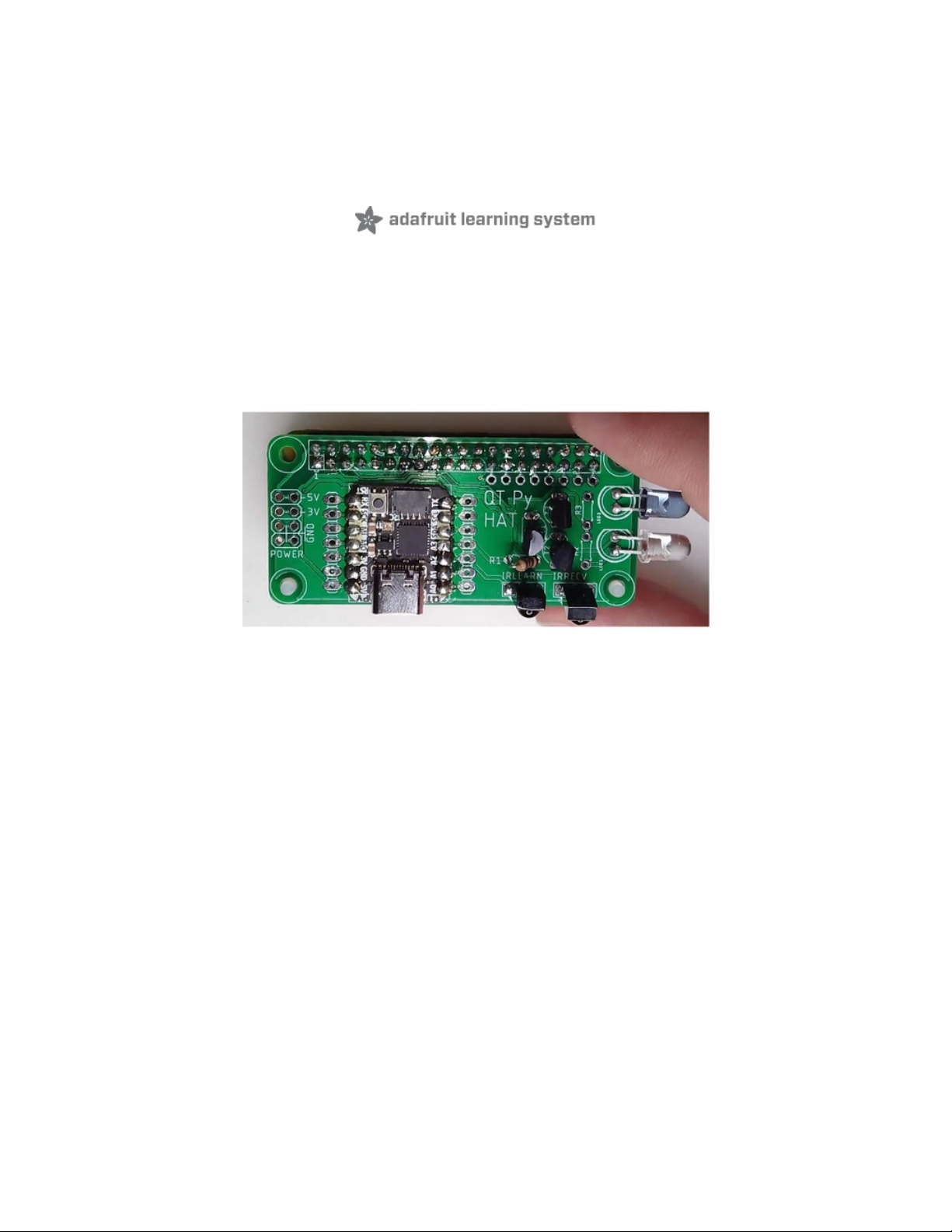
It is based on a Raspberry Pi Zero W and Adafruit QT Py-SAMD21. The QT Py is soldered to a custom
open-source Hat that attaches to the Raspberry Pi Zero W.
The board, called the QT Py Hat, was designed by Bill Binko. The Hat also contains infrared transmit and
receive circuitry. The Raspberry Pi communicates with the QT Py through the UART RX and TX pins via
the hat. There is also the option to connect I C or SPI interfaces of the two boards through the hat via
various jumpers.
Although a Raspberry Pi on its own could do infrared output, it would have to do so via bit-bang because it
cannot do PWM output to the IR LED driver circuit. It would require complicated drivers. It ties up the
processor which could cause an interruption in other activities such as Wi-Fi data coming and going. By
handing off the IR processing to the QT Py, it simplifies the entire process and makes it more reliable.
The combination of Raspberry Pi and QT Py provides for a variety of other potential uses such as adding
analog I/O to the Raspberry Pi. We will only be concentrating on the infrared aspects of this system but
future software updates will make it easier to use the other functions of the QT Py as well as its STEMMA
QT interface.
2
© Adafruit Industries https://learn.adafruit.com/iot-ir-remote-using-raspberry-pi-zero-w-and-qtpy-hat Page 3 of 41
Page 4

Here is a YouTube video demonstrating how the device works to control my TV and Cable DVR box. Note
it can be reconfigured for most any consumer electronic device such as a Blu-ray player or even an old
VCR that uses an infrared remote.
Project History
Here's a brief personal history of how this project came to be. It's not necessary to know this to build the
project but I thought you might find it interesting.
Several years ago I purchased a commercially available web-based IR remote called a "RedEye Remote"
however its web interface was dependent upon a cloud-based server. When the company went bankrupt,
the device became a useless brick. Then I developed my own solution using an Arduino compatible board
called Pinochio. (That's how they spelled it to avoid potential trademark infringement.) It was an early
system providing IoT capabilities. Unfortunately, it too relied on a cloud service that eventually
disappeared.
My next solution was to use an Arduino Yún which was the first official Arduino product supporting IoT. It
consisted of a small Linux system running WRT and was interfaced with what was essentially an Arduino
Leonardo based on the ATMEGA 32u4. My infrared transmit and receive library IRLib2 already supported
the 32u4 so it was a natural choice although somewhat expensive at approximately $75.
The Yún was eventually discontinued. Fortunately, my solution did not rely on any cloud-based systems
and was based entirely on my local Wi-Fi system so it continues to work to this day. There is now a
revision 2 of the Yún that sells for about $56 which is still a little bit expensive.
I was recently contacted by Ean Price who works with an organization that provides assistive technology
solutions to people in Canada. He had seen a video I did about various assistive technology gadgets I
have built and among them was the Yún-based device. He wanted to build one for himself and perhaps as
many as 5 more people. Long-term he speculated they might create as many as 50 of the devices.
After a brainstorming session with Bill Binko of ATMakers.org (https://adafru.it/RF6), we concluded that the
Yún was expensive old technology and if we were going to be assisting lots of clients with such devices
we could come up with a simpler more cost-effective solution. The result is the QT Py Hat project we
present here.
Although designed to be an IR remote, it also is an extremely cost-effective alternative to the Yún. It does
not yet have the software support of the Yún but we will be working to develop this platform further in the
near future.
© Adafruit Industries https://learn.adafruit.com/iot-ir-remote-using-raspberry-pi-zero-w-and-qtpy-hat Page 4 of 41
Page 5
Parts Required
Here is a list of everything you will need for this project.
Raspberry Pi Items
Although this project can use any Raspberry Pi that has Wi-Fi capability which includes the various
varieties of models 3 and 4, we recommend the Raspberry Pi Zero W or Raspberry Pi Zero WH. The "WH"
is identical to the "W" model except that it has the headers pre-soldered. If you already have 2 x 20 pin
headers available you can save $4 and solder them yourself.
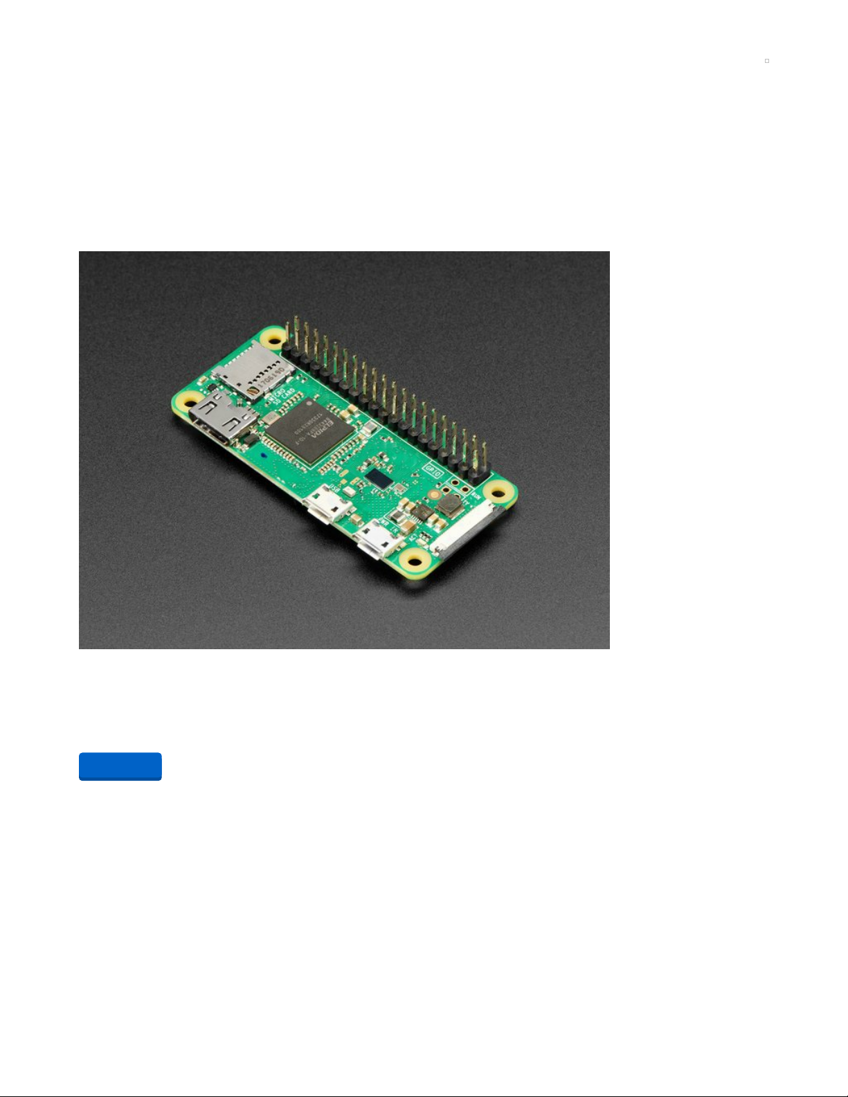
Raspberry Pi Zero WH (Zero W with Headers)
If you didn't think that the Raspberry Pi Zero W could possibly get any better, then boy do we have a
pleasant surprise for you! The new Raspberry Pi Zero...
$14.00
In Stock
You will need a 5V power supply. We recommend this 2.5 amp supply with a micro USB cable already
attached.
Add to Cart
© Adafruit Industries https://learn.adafruit.com/iot-ir-remote-using-raspberry-pi-zero-w-and-qtpy-hat Page 5 of 41
Page 6
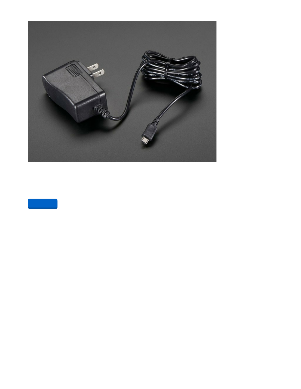
5V 2.5A Switching Power Supply with 20AWG MicroUSB Cable
Our all-in-one 5V 2.5 Amp + MicroUSB cable power adapter is the perfect choice for powering singleboard computers like Raspberry Pi, BeagleBone or anything else that's power...
$7.50
In Stock
You will need a microSD card for the operating system. It should be at least 8Gb. You will need the
capability of reading and writing information to this card from your PC or laptop. Although you can
purchase an SD card with the NOOBS operating system preinstalled, we have not used that method and
so the procedures we outline here will not exactly be the same. So we recommend getting a plain card
and downloading NOOBS yourself.
Add to Cart
© Adafruit Industries https://learn.adafruit.com/iot-ir-remote-using-raspberry-pi-zero-w-and-qtpy-hat Page 6 of 41
Page 7

SD/MicroSD Memory Card - 16GB Class 10 - Adapter Included
Add speedy mega-storage in a jiffy using this 16 GB Class 10 micro-SD card. It comes with a SD adapter so
you can use it with any of our shields or adapters! Preformatted to FAT so it...
$19.95
In Stock
We will be configuring the Raspberry Pi Zero W as a "headless" device. That means it will not need a
monitor, keyboard or mouse. If you intend to use the Pi Zero W for other purposes you might want to
consider getting an HDMI cable, Mini-HDMI to HDMI adapter, USB OTG cable, and USB Console cable as
recommended on the Raspberry Pi Zero W product page (https://adafru.it/vMD).
QT Py and Accessories
This project is designed to work with the Adafruit QT Py-SAMD21. In addition to the board itself, you will
also need a USB C cable for programming it.
Note that the QT Py Hat has been designed with the upcoming RP 2040 version of the QT Py board in
mind however, the software included in this tutorial is not compatible with the RP 2040 because it uses
the Arduino IDE C++ as well as IRLib2 neither of which currently support the RP 2040. The IRLib2 library
may eventually support the RP 2040 processor and we will update the software when that capability is
available.
Your browser does not support the video tag.
Adafruit QT Py - SAMD21 Dev Board with STEMMA QT
What a cutie pie! Or is it... a QT Py? This diminutive dev board comes with our favorite lil chip, the SAMD21
(as made famous in our GEMMA M0 and Trinket M0 boards).For...
Out of Stock
Add to Cart
© Adafruit Industries https://learn.adafruit.com/iot-ir-remote-using-raspberry-pi-zero-w-and-qtpy-hat Page 7 of 41
Page 8
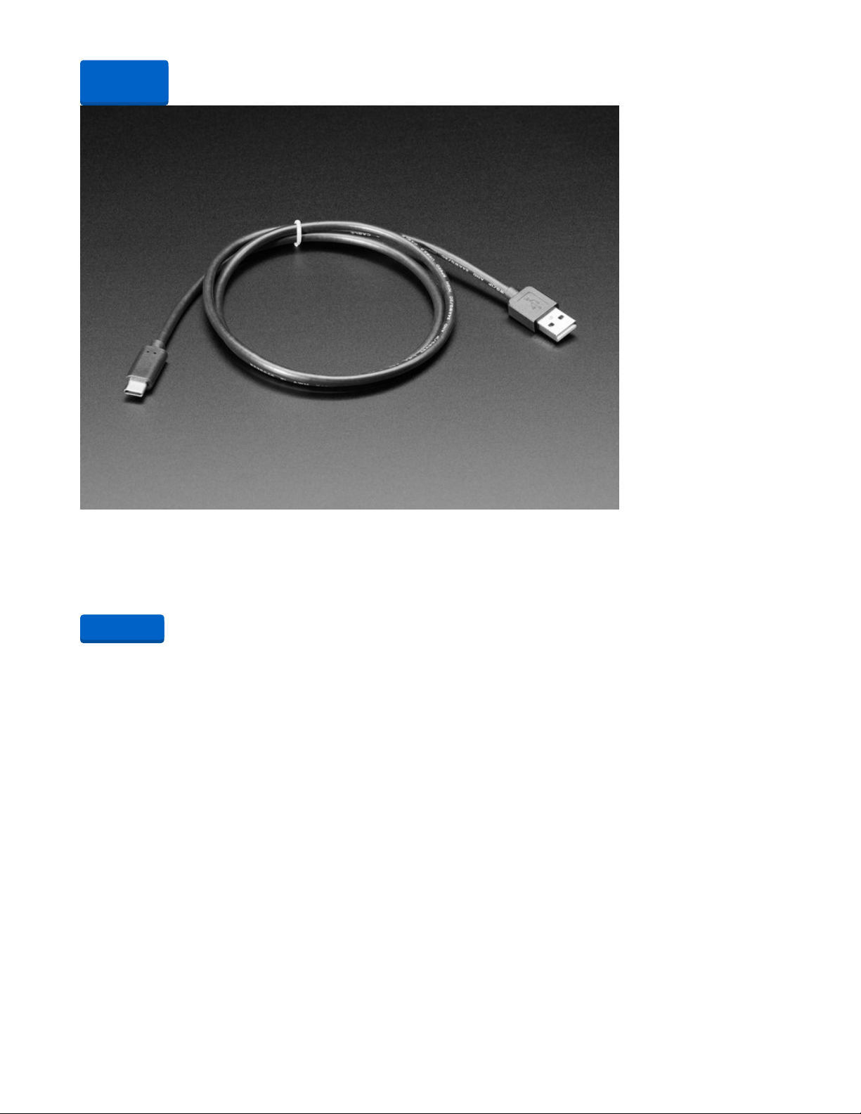
USB Type A to Type C Cable - approx 1 meter / 3 ft long
As technology changes and adapts, so does Adafruit. This USB Type A to Type C cable will help you with
the transition to USB C, even if you're still...
$4.95
In Stock
Although not necessary for this project, you might also want to consider getting the 2 MB SPI 8 pin addon memory chip. The QT Py Hat board has a hole in it to accommodate this chip which might be useful for
future projects.
Out of
Stock
Add to Cart
© Adafruit Industries https://learn.adafruit.com/iot-ir-remote-using-raspberry-pi-zero-w-and-qtpy-hat Page 8 of 41
Page 9
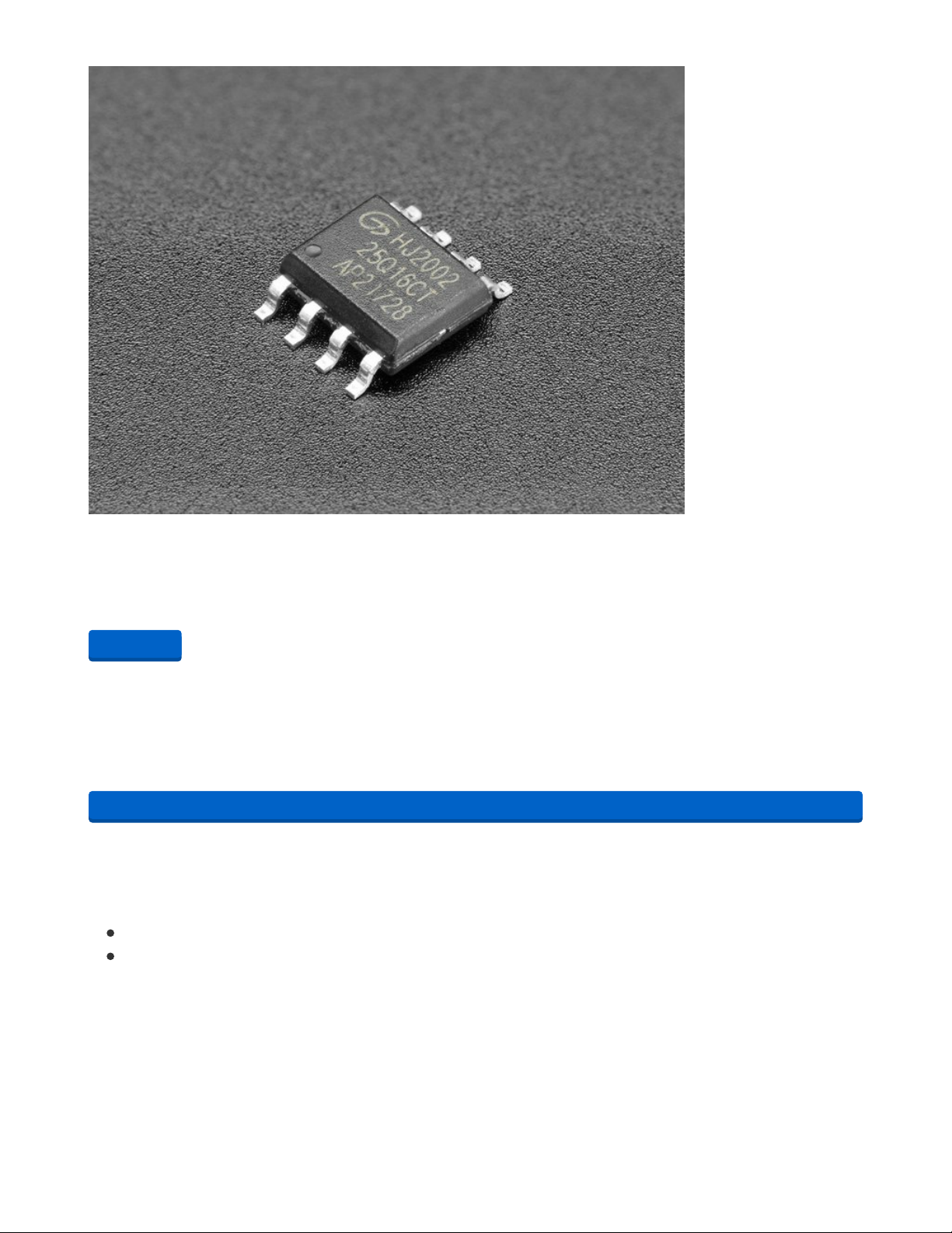
GD25Q16 - 2MB SPI Flash in 8-Pin SOIC package
These little chips are like miniature SSD drives for your electronics. When you don't need something with
as much storage as a micro SD card, but an EEPROM is too small, SPI (or...
$1.25
In Stock
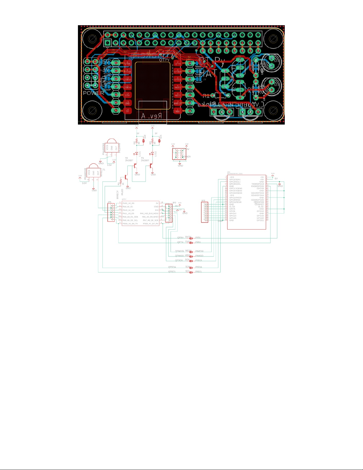
QT Py Hat Board and Components
The QT Py circuit board is an open-source board. The Eagle CAD files for the board are available in a
GitHub repository that you can download at the button below. The same repository also contains all of the
software necessary for the project as well as STL files for a 3D printed case. You should download it now
for later use.
https://adafru.it/RF7
You can submit the board files to your favorite board manufacturer,
make the board yourself or you can also order the board directly from
the following vendors
QT Py Hat at PCBWay.com (https://adafru.it/RF8)
QT Py Hat at OSHPark.com (https://adafru.it/RF9)
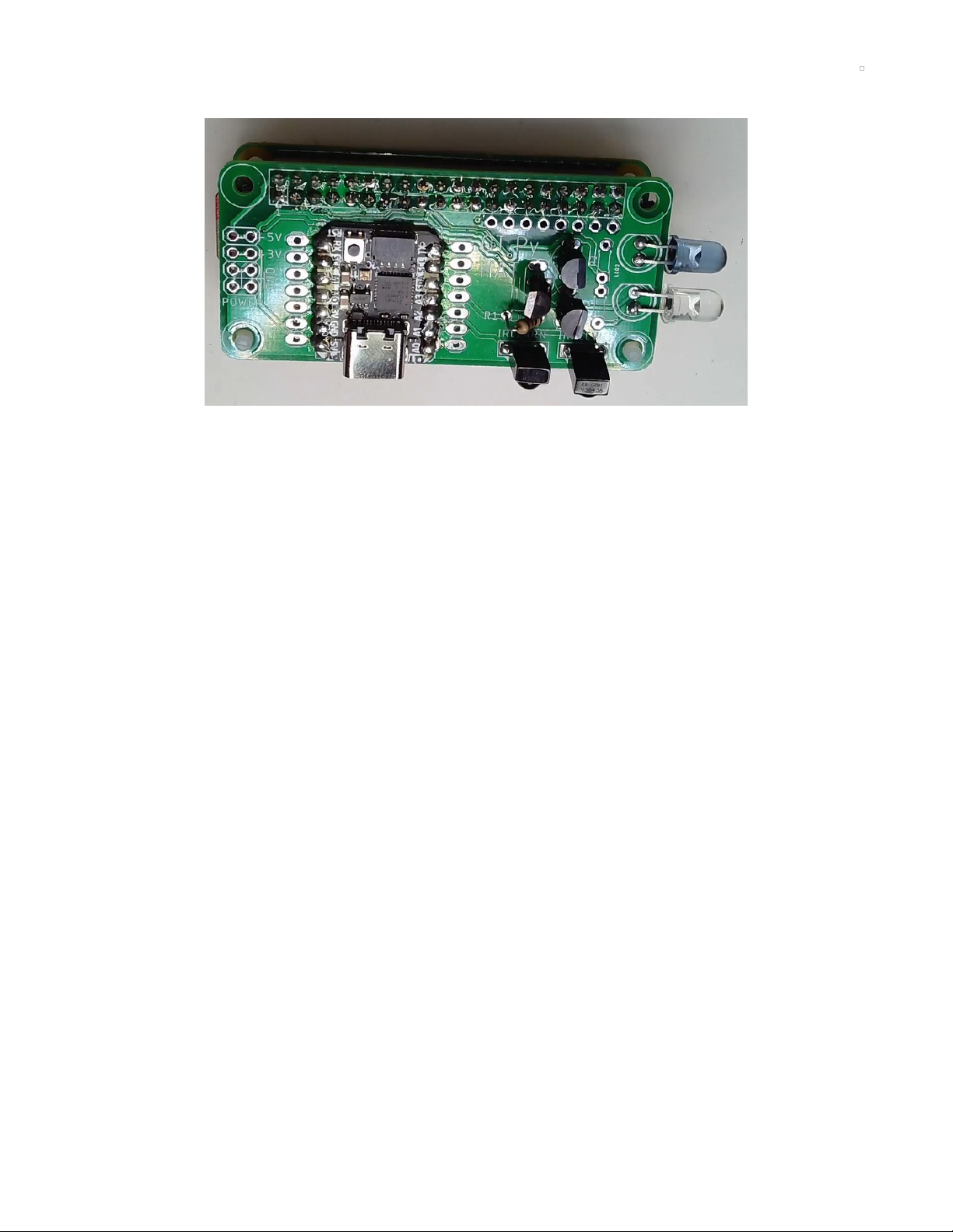
Here are images of the board and schematics.
Add to Cart
https://adafru.it/RF7
© Adafruit Industries https://learn.adafruit.com/iot-ir-remote-using-raspberry-pi-zero-w-and-qtpy-hat Page 9 of 41
Page 10
You will also need a number of through-hole components. Most of the parts you will need are available
from Adafruit. Some that are not available at Adafruit are available from a variety of suppliers. At the end
of this list will give you a complete list of through-hole parts available from Digi-Key.
First, we will need 2 IR LEDs. We prefer to use a combination of wide-angle and narrow-angle LEDs. This
narrow 20° angle LED is available from Adafruit. A 40° wide-angle LED is available from Digi-Key. See the
Digi-Key parts list at the end.
© Adafruit Industries https://learn.adafruit.com/iot-ir-remote-using-raspberry-pi-zero-w-and-qtpy-hat Page 10 of 41
Page 11
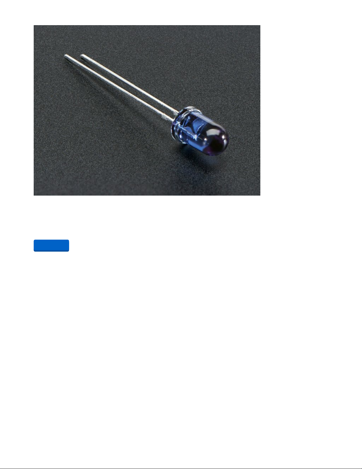
Super-bright 5mm IR LED
Infrared LEDs are used for remote controls (they're the little LED in the part you point at your TV) and
'night-vision' cameras, and these little blue guys are high powered...
$0.75
In Stock
You will also need an NPN transistor and 2 PNP transistors. Here Adafruit has a combo pack of five of
each or you can buy them separately in packs of 10.
Add to Cart
© Adafruit Industries https://learn.adafruit.com/iot-ir-remote-using-raspberry-pi-zero-w-and-qtpy-hat Page 11 of 41
Page 12
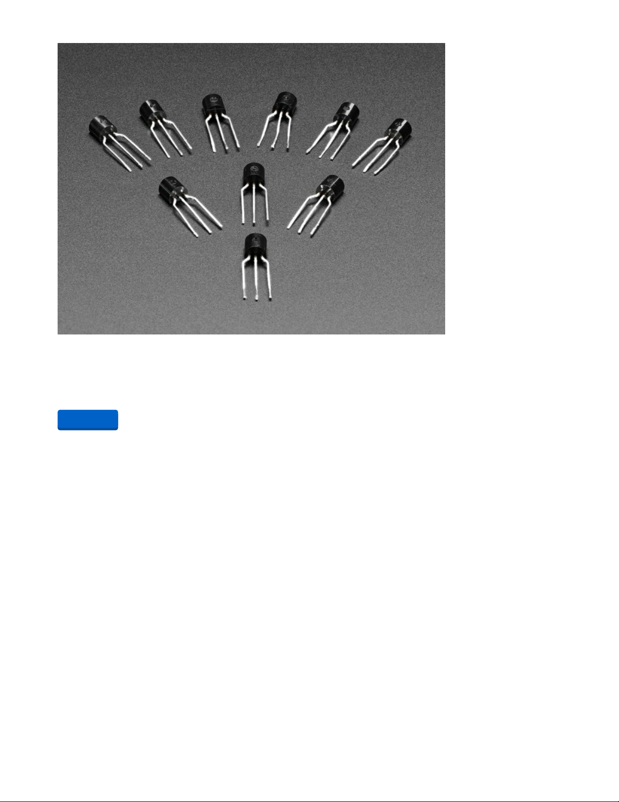
Bipolar Transistor Kit - 5 x PN2222 NPN and 5 x PN2907 PNP
Transistors are powerful little electronic switches, and we really like these NPN and PNP transistors
whenever we need to control medium-power electronics, such as small motors,...
$1.95
In Stock
You will need a 1K ohm resistor and optionally you may need two 33 ohm resistors. Adafruit carries the 1K
variety but if you need the 33 ohm see the Digi-Key parts list at the end of the page. We will explain later
why you may or may not need the 33 ohm resistors.
Add to Cart
© Adafruit Industries https://learn.adafruit.com/iot-ir-remote-using-raspberry-pi-zero-w-and-qtpy-hat Page 12 of 41
Page 13

Through-Hole Resistors - 1.0K ohm 5% 1/4W - Pack of 25
ΩMG! You're not going to be able to resist these handy resistor packs! Well, axially, they do all of the
resisting for you!This is a 25 Pack of...
$0.75
In Stock
You will need an infrared receiver such as this TSOP38238 from Adafruit. In the Digi-Key parts list, we
specify a TSOP38438 which has a slightly better automatic gain control circuit however the 38238 from
Adafruit will work fine under most every circumstance. You may also need an infrared learner device the
TSMP 58000 from Digi-Key. We will explain later why you might need a TSMP58000.
Add to Cart
© Adafruit Industries https://learn.adafruit.com/iot-ir-remote-using-raspberry-pi-zero-w-and-qtpy-hat Page 13 of 41
Page 14

IR (Infrared) Receiver Sensor
IR sensor tuned to 38KHz, perfect for receiving commands from a TV remote control. Runs at 3V to 5V so
it's great for any microcontroller.To use, connect pin 3 (all the...
$1.95
In Stock
The board requires a 2x20 pin female header to connect it to the Raspberry Pi.
Add to Cart
© Adafruit Industries https://learn.adafruit.com/iot-ir-remote-using-raspberry-pi-zero-w-and-qtpy-hat Page 14 of 41
Page 15

GPIO Header for Raspberry Pi A+/B+/Pi 2/Pi 3/Pi 4/Zero
Connect your own PCB to a Raspberry Pi with this normal-height female header. The female header part
is about 8.5mm tall, good for small HATs that do not to clear the...
$1.50
In Stock
Here is a parts list for the through-hole parts from Digi-Key.
1 -- IR333C/H0/L10 IR LED 40° angle from Digi-Key (https://adafru.it/FD-)
1 -- IR333A 20° angle from Digi-Key (https://adafru.it/FE0)
1 -- 1k ohm resistor from Digi-Key (https://adafru.it/FE1)
2 -- 33 ohm resistors from Digi-Key (optional) (https://adafru.it/FE2)
1 -- PN2222 NPN transistor TO-92 case from Digi-Key (https://adafru.it/FE3)
2 -- PN2709 PNP transistor TO-92 case from Digi-Key (https://adafru.it/FE4)
1 -- TSOP 38438 38 kHz IR receiver module from Digi-Key (https://adafru.it/FE5)
1 -- TSMP 58000 IR learner module from Digi-Key (https://adafru.it/FE6)
Other items
You will need a soldering iron, solder, and diagonal cutters to install the through-hole components and
clip the leads. A small vice for holding the PCB while you solder it will be useful as well.
Add to Cart
© Adafruit Industries https://learn.adafruit.com/iot-ir-remote-using-raspberry-pi-zero-w-and-qtpy-hat Page 15 of 41
Page 16

QT Py Hat Assembly
Here is a YouTube video that provides step-by-step instructions on how to assemble the QT Py Hat
board.
If you'd rather not watch the entire video, here are the steps to assemble the board. Some of these steps
are in a different order than what we did in the video.
1. Solder in all of the through-hole components. There are two kinds of IR LEDs. The clear one is a 40°
wide-angle LED and the blue-tinted one is a 20° narrow-angle LED. Either one can go in either
position. The short wire is the cathode and it should go towards the flat side of the circle printed on
the circuit board. The long wire is the anode and to should in the other hole. Do not put the LEDs
flush with the circuit board. Leave the leads along so that you can bend the LEDs over 90° as seen in
the photographs and video.
2. There are two PN2907 PNP transistors and a single PN2222 NPN transistor. These components
appear identical so make sure that you get the proper ones in the proper slots. They should be
oriented according to the printing on the circuit board.
3. There is a 1K ohm resistor. The hole spacing is a little bit narrow so this component cannot be
installed flush against the board but that's okay. Also, there is no polarity on a resistor so the
orientation doesn't matter.
4. Solder in the 40 pin (2x 20) female header on the underneath side of the board with the pins coming
through the top side. Make sure it is flush against the board. We have waited to install this
component later so that you don't accidentally bump into it with a soldering iron when installing the
through-hole components.
5. Finally, solder the QT Py board to the circuit board. Start by tacking one corner in place and check to
make sure the board is straight. You can reheat that first attach point to adjust the position. Once it is
in place, solder the rest of the pads. See the video for details.
If you purchased a Raspberry Pi Zero W without headers you will need to solder in a 40 pin (2x20) male
header on the top of the Raspberry Pi Zero W.
Do not attach the two boards together until we have tested the boards separately.
Optional Features
The infrared transmitter circuit on this board is based on a previous board I designed which you can read
about here (https://adafru.it/FM3). For some applications, the power requirements of the infrared LEDs can
be excessive. We mentioned that a previous version of this project used an Arduino Yún. If we used the
full power of the IR LEDs that board would sometimes crash. So we designed an optional 33-ohm resistor
that you can put inline with the IR LEDs. Our testing using a Raspberry Pi Zero W has shown that these
extra current limiting resistors are not necessary. But if you have another application and you believe that
the IR LEDs are drawing too much power then you can cut the traces on the backside of the board and
solder in a pair of 33-ohm resistors.
© Adafruit Industries https://learn.adafruit.com/iot-ir-remote-using-raspberry-pi-zero-w-and-qtpy-hat Page 16 of 41
Page 17

The TSOP 38438 is an infrared receiver that is tuned to 38 kHz. Our experience is that it is also capable of
reading signals modulated from 36-40 kHz which encompasses most of the IR protocols in use today. We
will use this device to determine signals from your existing remote so that we can program this device to
re-create them. Unfortunately, one particular protocol "Panasonic Old" protocol #5 uses 56 kHz
modulation. It is unlikely that the TSOP 38438 will be able to decode it.
The TSMP 58000 is a learning chip. It receives modulated signals directly regardless of frequency. For
the time being, it can only be used to determine the frequency of the incoming signal.
For now, we will have to do things the hard way. We will receive the IR signals using the TSOP 38438 and
decode them into 32-bit codes for each function. We will then have to manually edit that 32-bit code into
our software along with a protocol number and some other information about the function.
Eventually, we will have new software that will turn this device into a more traditional learning remote
where you can simply point your IR remote at this device and it will record it and play it back faithfully. For
now, the TSMP 58000 isn't completely necessary however when we get that software developed, the
TSMP 58000 device will be essential.
© Adafruit Industries https://learn.adafruit.com/iot-ir-remote-using-raspberry-pi-zero-w-and-qtpy-hat Page 17 of 41
Page 18

Other optional jumpers and solder holes are available on the QT Py Hat that are not necessary for this
particular project. However, they could be quite useful for other applications of the Hat. They are
explained in the YouTube video at the top of this page.
© Adafruit Industries https://learn.adafruit.com/iot-ir-remote-using-raspberry-pi-zero-w-and-qtpy-hat Page 18 of 41
Page 19

QT Py Software
Download the Software
The software for this project is available on GitHub at the following link. It also contains board files for the
open-source circuit board and STL files for a 3D printing case. If you have not already done so, download
it and unzip it to your computer. We will describe later what to do with the various programs and folders.
https://adafru.it/RF7
The repository contains 4 folders. The folder arduino_files contains files that we will upload to the QT Py
Board using the Arduino IDE. The folder raspberry_pi_files contains files that will be copied to your
Raspberry Pi. The folder CAD_files contains the STL files for the 3D printed case. The folder board_files
contains the Eagle CAD files for the circuit board.
Installing IRLib2
We will also be using IRLib2 which is an open-source library for transmitting, receiving, and decoding
infrared signals. The library is available on GitHub at the following link…
https://adafru.it/vwF
That library cannot be installed using the Arduino Library Manager. You have to install it manually.
Installation of the IRLib2 library is as follows:
1. Visit the IRLib2 page on GitHib (https://adafru.it/vwF).
2. Select the “Download ZIP” button, or simply click this link (https://adafru.it/vxa) to download directly.
3. Uncompress the ZIP file after it’s finished downloading.
4. The resulting folder should be named "IRLib2-master" and will contain 5 separate folders. That is
because IRLib 2.x is actually a collection of 5 libraries that work together. Sometimes, you’ll get an
intermediate-level folder and need to move things around.
5. Copy all five folders into your Arduino library folder alongside your other Arduino libraries, typically
in your (home folder)/Documents/Arduino/Libraries/ folder. Libraries should not be installed alongside
the Arduino application itself.
6. Re-start the Arduino IDE if it’s currently running
This repository consists of a total of five libraries each of which must be in your arduino/libraries/ folder. So
for example it should be installed as follows…
arduino/libraries/IRLib2
arduino/libraries/IRLibFreq
arduino/libraries/IRLibProtocols
arduino/libraries/IRLibRecv
arduino/libraries/IRLibRecvPCI
Do not install them in a single folder such as this…
arduino/libraries/IRLib2_master
IRLib2
https://adafru.it/RF7
https://adafru.it/vwF
© Adafruit Industries https://learn.adafruit.com/iot-ir-remote-using-raspberry-pi-zero-w-and-qtpy-hat Page 19 of 41
Page 20

IRLibFreq
IRLibProtocols
IRLibRecv
IRLibRecvPCI
Here is a tutorial (https://adafru.it/m3e) that walks through the process of manually installing libraries that
are not available through the library manager.
After you have installed the library, look in the IRLib2/manuals folder. You will find an extensive set of
documentation for the library in EPUB e-book format, PDF format, and Microsoft Word .docx format.
Section 2 of that manual is a tutorial on the basic use of the library. Below you will find some brief
explanation of how to use a board but for complete details, you should really use the examples in section
2 of the IRLib manual.
The IR transmitter and receiver circuits in this board are based on an IR circuit that has its own tutorial
here in the Adafruit Learning System. There is also a learning guide for IRLib2 itself. See the following
links.
Building an Infrared Transmitter and Receiver Board (https://adafru.it/FM3)
Using an Infrared Library on Arduino (https://adafru.it/vxc)
If you are not familiar with how to upload programs written in C++ to the QT Py SAMD21, see the learning
guide for that board, especially this section on using the Arduino IDE (https://adafru.it/OZD).
© Adafruit Industries https://learn.adafruit.com/iot-ir-remote-using-raspberry-pi-zero-w-and-qtpy-hat Page 20 of 41
Page 21

Testing the QT Py Hat
Testing the Receivers
In the GitHub repository that you downloaded, there are several sample programs that we will use to test
the IR features of the QT Py Hat. They are located in the "arduino_files" folder.
Do not yet attach the QT Py Hat to your Raspberry Pi Zero W.
Connect the QT Py to your PC using a USB C cable. Get the program arduino_files/dumpFreq and upload it
using the Arduino IDE. Open your serial monitor.
Get an infrared remote for your TV, cable DVR, or another consumer electronic device and point it at the
receiver chips on the QT Py Hat and press a button. The program will attempt to decode your signal. If
successful, it will tell you the protocol number used by IRLib2, the code for that particular button that
could be up to 32-bit long, and other information depending on the type of protocol. It might be the
number of bits or an additional address field. Here is a sample output after I pressed the "Volume Up",
"Volume Down", "Mute", and "Power" buttons on my Samsung TV remote.
Frequency interrupt=2 Pin=2
Receiver interrupt=1 Pin=1
Number of samples:243 Total interval (us):6380
Avg. interval(us):26.26 Aprx. Frequency(kHz):38.09 (38)
Decoded NECx(7): Value:E0E0E01F Adrs:0 (32 bits)
Number of samples:243 Total interval (us):6367
Avg. interval(us):26.20 Aprx. Frequency(kHz):38.17 (38)
Decoded NECx(7): Value:E0E0D02F Adrs:0 (32 bits)
Number of samples:243 Total interval (us):6372
Avg. interval(us):26.22 Aprx. Frequency(kHz):38.14 (38)
Decoded NECx(7): Value:E0E0F00F Adrs:0 (32 bits)
Number of samples:243 Total interval (us):6359
Avg. interval(us):26.17 Aprx. Frequency(kHz):38.21 (38)
Decoded NECx(7): Value:E0E040BF Adrs:0 (32 bits)
The first two lines just tell us which pin numbers and interrupt numbers are used for the IR receivers on
this device. We can ignore that.
The next two lines tell us information about the frequency detection of the signal for the "Volume Up"
button press. The "(38)" at the end of the second line of information tells us that this is a 38 kHz
modulated signal which is the most common kind. IR signals range from about 36 kHz up to 56 kHz.
The next line tells us that it successfully decoded the "NECx" protocol which is protocol number 7 in the
IRLib2 system. The value that it decoded was the 32-bit hexadecimal value E0E0E01F. This particular
protocol does not make use of the address field so it returns zero. And we are told this is a 32-bit
protocol.
The remaining pairs of lines are identical except that they returned a different hexadecimal code. The
code for "Volume Down" is E0E0D02F, the "Mute" button is E0E0F00F, and finally, the "Power" button is
E0E040BF.
If the frequency is somewhere in the 56-58 kHz range then it is likely that the protocol is protocol 5
"Panasonic Old" and it is unlikely that you will be able to successfully decode the data value using the
TSOP 38438. Future versions of the software will allow for decoding such protocols. We will have more
© Adafruit Industries https://learn.adafruit.com/iot-ir-remote-using-raspberry-pi-zero-w-and-qtpy-hat Page 21 of 41
Page 22

info later in this tutorial about what to do if your protocol is not recognized.
Once you are convinced that you're getting reasonable readings from the receivers, we can try testing the
transmitter.
Upload the program arduino_files/record and open the serial monitor. Now point your infrared remote at
the receivers and press a button that you can easily test. We recommend something like the "Mute"
button on your TV. The program will record that signal. Then click on the input line on the serial monitor
and press enter. The program will re-transmit the code that it recorded. If you continue sending
characters from the serial monitor it will continue to resend that same signal that it recorded until you
record a different one.
This should confirm that the IR LEDs and driver circuit is working properly.
In the next section, Set up the software on your Raspberry Pi Zero W. In the final section, we will put
everything together and begin configuring your IoT remote for your particular devices.
© Adafruit Industries https://learn.adafruit.com/iot-ir-remote-using-raspberry-pi-zero-w-and-qtpy-hat Page 22 of 41
Page 23
Raspberry Pi Zero W Software and Setup
Setting up the Raspberry Pi
The normal operation of this project Is that your Raspberry Pi Zero W will be operated "headless" which
means that it will only be operated remotely over your Wi-Fi network without a monitor, mouse, or
keyboard.
As mentioned previously you will need a PC that has an SD card reader so that you can download the
software and install it to the card. Insert the SD card into the card reader on your PC.
Installing NOOBS
We will be using a system called NOOBS which is an easy way to prepare an SD card with an operating
system for a Raspberry Pi.
Go to the Raspberry Pi software download page here:
https://www.raspberrypi.org/software/ (https://adafru.it/QbQ)
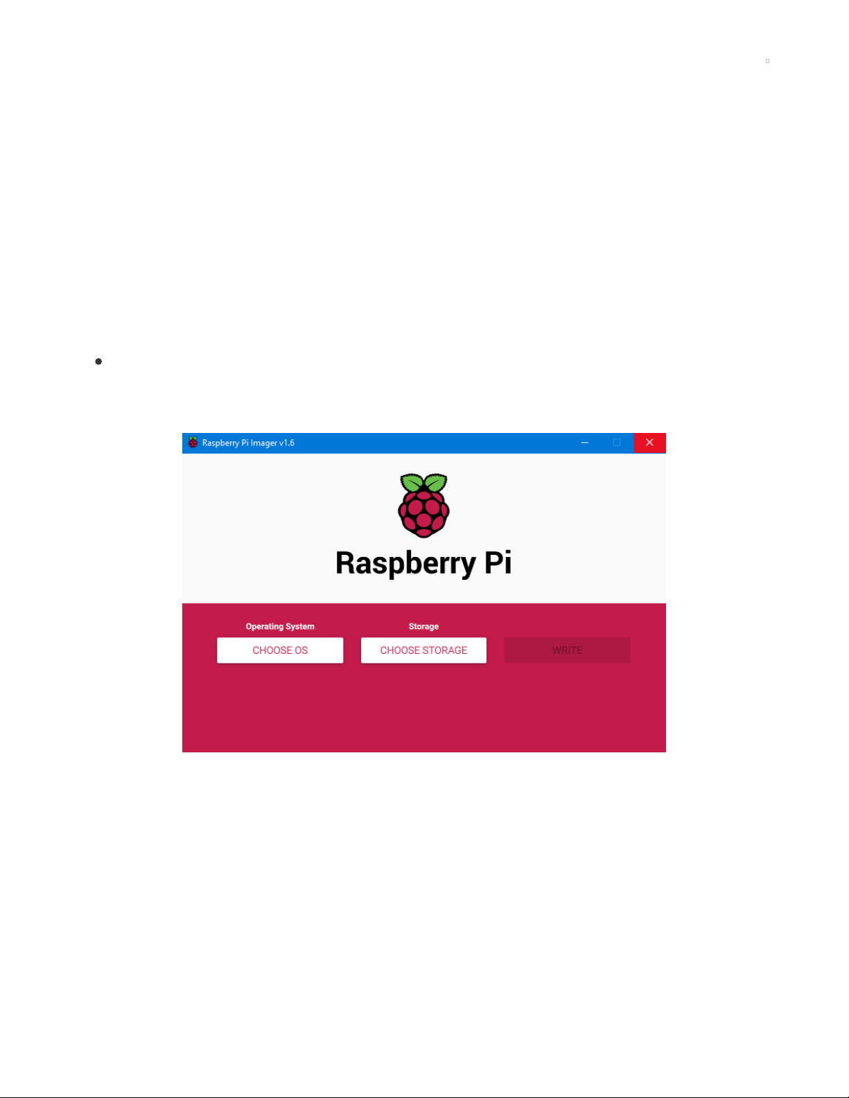
Download the appropriate installer for your computer whether it be Windows, Mac, or Ubuntu for
x86. When you run the imager program you will see this screen.
Click on the left-hand button of the imager program to choose your operating system. But before
choosing which operating system to install, press CTRL + SHIFT + X
You will see a screen that looks like this
© Adafruit Industries https://learn.adafruit.com/iot-ir-remote-using-raspberry-pi-zero-w-and-qtpy-hat Page 23 of 41
Page 24
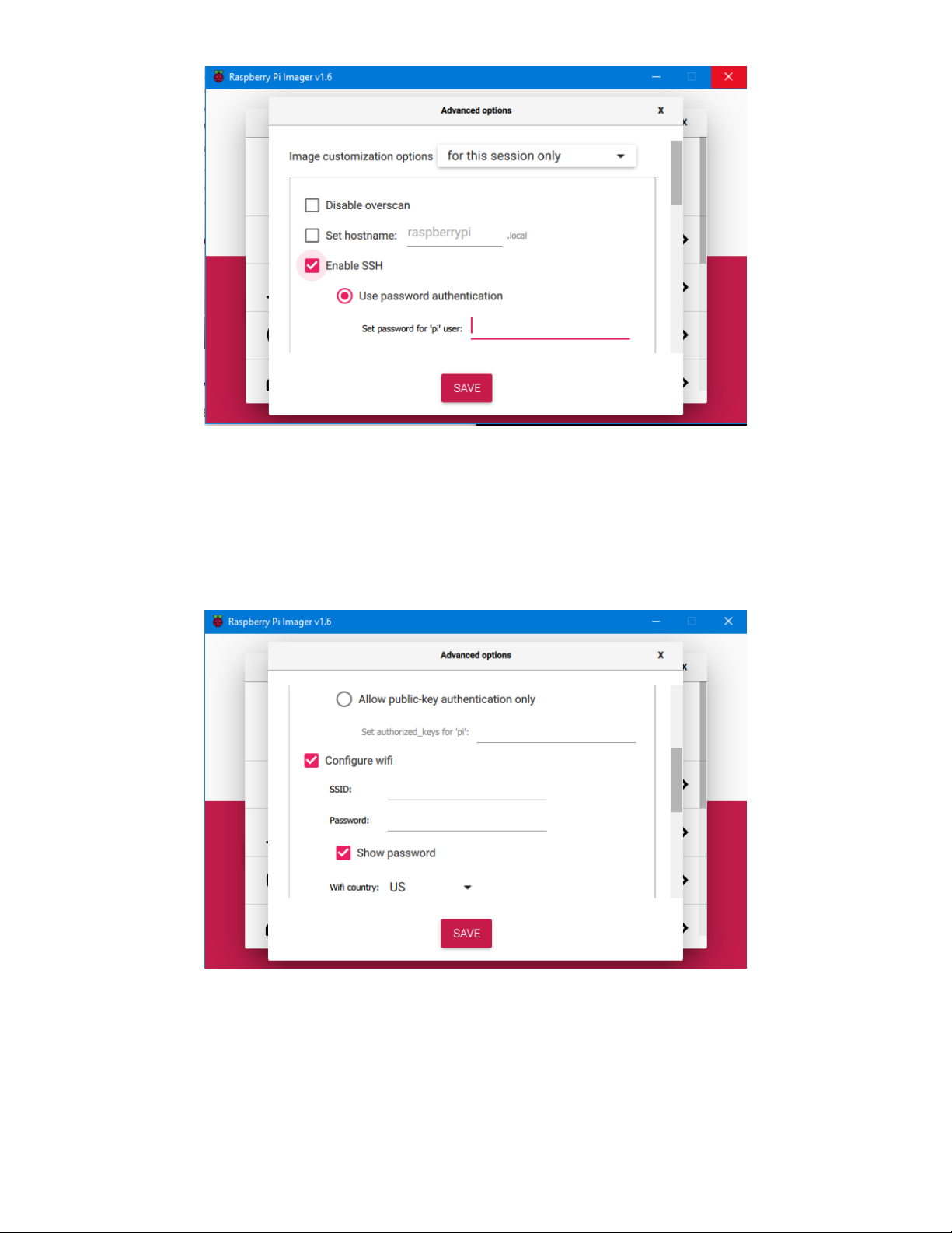
The overscan option doesn't apply because we won't be using a monitor. You can optionally create your
own hostname which will be handy if you're going to create more than one of these devices or you have
other Raspberry Pi devices on your Wi-Fi network. You should check "Enable SSH" and choose a
password as shown above.
Then scroll down to the next section to set up your Wi-Fi SSID and password. Set your country ID. NOTE
we do not recommend checking the "Allow public-key authentication" option at the top because honestly,
we don't know what that means :-) We got by without it.
Scroll down further and optionally set the locale and keyboard layout. We suggest you skip the first run
wizard. The other persistent settings you can leave or change according to your own wishes. When done,
click on the SAVE button
© Adafruit Industries https://learn.adafruit.com/iot-ir-remote-using-raspberry-pi-zero-w-and-qtpy-hat Page 24 of 41
Page 25
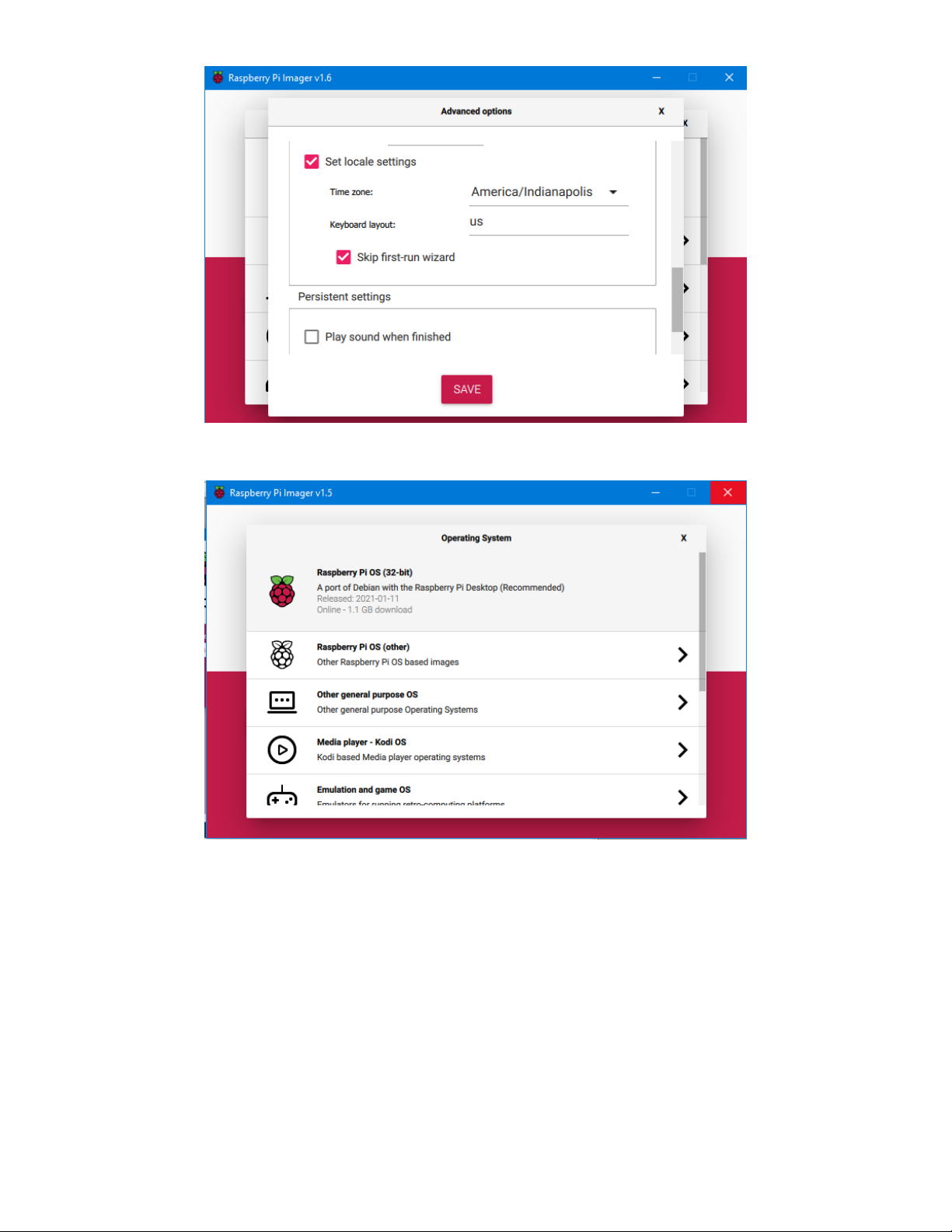
Now select the top option "Raspberry Pi OS (32-bit)" then on the next screen click the middle button to
choose the drive on your PC where the SD card is located.
Then complete the process of writing and verifying the image. When complete, remove the SD card from
your PC, insert it into your Raspberry Pi Zero W, and power up the device by inserting a USB cable into
the power connector. Note that there are 2 micro USB ports so be sure to connect to the power port.
© Adafruit Industries https://learn.adafruit.com/iot-ir-remote-using-raspberry-pi-zero-w-and-qtpy-hat Page 25 of 41
Page 26

Connecting to Wi-Fi
Next, we need to determine the IP address of the Raspberry Pi Zero W on your local Wi-Fi network.
Typically you could go to the setup page of your router which is usually http://192.168.1.1/ but may be
different for your system. On my Linksys router on the start page, I click on "DHCP Reservation" and I see
a screen like this. Look for the Raspberry Pi in the list of devices.
For further information on how to determine the IP address of your Raspberry Pi check out this page from
the Raspberry Pi documentation.
https://www.raspberrypi.org/documentation/remote-access/ip-address.md (https://adafru.it/RFa)
Once you have the IP address, you need to use a terminal program to connect to the Raspberry Pi via
SSH. I like to use the free program MobaXterm which can be downloaded here (https://adafru.it/RFb). You
can also use PuTTY or any other program that can use SSH. MobaXterm is nice because it also lets you
use SFTP to easily transfer files. We also will be recommending you set up your Raspberry Pi with a
samba server which will make file transfers much easier. Here's a link on how to use PuTTY to connect to
your Raspberry Pi.
© Adafruit Industries https://learn.adafruit.com/iot-ir-remote-using-raspberry-pi-zero-w-and-qtpy-hat Page 26 of 41
Page 27

https://www.raspberrypi.org/documentation/remote-access/ssh/windows.md (https://adafru.it/RFc)
Here is more information about how to use SSH to connect to a Raspberry Pi and includes specific
suggestions for other operating systems besides Windows.
https://www.raspberrypi.org/documentation/remote-access/ssh/ (https://adafru.it/vbC)
When you have connected via SSH, you should log in using the username "pi" and the password that you
specified for SSH when you did the initial installation on the SD card. If you're using PuTTY you will get a
pop-up warning the first time you connect. You can ignore the warning.
Initial Configuration
One of the first things you should always do with a new Linux installation is to make sure that everything is
up-to-date using the following 2 commands. This can take several minutes.
sudo apt-get update
sudo apt-get upgrade
Next we need to run the Raspberry Pi configuration program with the command
sudo raspi-config
You will then see a screen like this. Choose the third option "Interface Options"
Go down to the 6th item to configure the serial port UART. We need to tell it not to use the serial port for
shell commands but to enable the UART. This is how we will communicate between the Raspberry Pi and
the QT Py Hat.
© Adafruit Industries https://learn.adafruit.com/iot-ir-remote-using-raspberry-pi-zero-w-and-qtpy-hat Page 27 of 41
Page 28

After selecting item P6 you will see the following screen to which you should answer "No"
On the next screen answer "Yes". When finished you may wish to enable other options on the screen
such as turning on access to SPI, I C, 1-Wire, and Remote GPIO. Note however none of those other
interfaces are necessary for this particular project but they may be useful for other applications of the QT
Py Hat.
When you go back to the main menu of the raspi-config program we recommend you choose option 6
"Advanced Options" And then choose option "A1 Expand Filesystem". Although this project requires
minimal space on your SD card, we've always found it handy to expand the filesystem on any Raspberry
Pi set up.
2
© Adafruit Industries https://learn.adafruit.com/iot-ir-remote-using-raspberry-pi-zero-w-and-qtpy-hat Page 28 of 41
Page 29

Enabling Samba Server
Although not completely necessary for this project, we also recommend setting up your Raspberry Pi with
a samba server. This will allow you to easily access the file system of your device as if it was another
computer on your network. You can drag-and-drop files, create folders, and edit files directly from your
PC.
Issue the following command via SSH on your Raspberry Pi
sudo apt-get install samba samba-common-bin
This command will take several minutes to execute. There will be some error messages which you can
ignore. At one point during installation, you will see the following pop-up message to which you should
answer "Yes".
© Adafruit Industries https://learn.adafruit.com/iot-ir-remote-using-raspberry-pi-zero-w-and-qtpy-hat Page 29 of 41
Page 30

You will then need to edit the samba configuration file to tell it which folder(s) that you wish to share over
your local network. I like using the "nano" editor but if you are more familiar with other editors on Linux
systems you can use anyone you like. We will use the following command
sudo nano /etc/samba/smb.conf
Scroll all the way to the bottom of the file. Note it is approximately 200 lines long. Add the following text
to the end of the /etc/samba/smb.conf file.
This will make your entire user "pi" file system available. If you don't want to expose that much of your
device over the samba interface you can create a folder and only share it.
[userpi]
Comment = Pi shared folder
Path = /home/pi
Browseable = yes
Writeable = Yes
only guest = no
create mask = 0777
directory mask = 0777
Public = yes
Guest ok = yes
© Adafruit Industries https://learn.adafruit.com/iot-ir-remote-using-raspberry-pi-zero-w-and-qtpy-hat Page 30 of 41
Page 31

Save the file using CTRL-O and exit using CTRL-X (or whatever commands on the editor you might use).
Then reboot the system using this command
sudo reboot
After the reboot, you should be able to access the file system of your Raspberry Pi user "pi" file system
with your File Explorer on your PC. The file system will be available at \\raspberrypi or if you changed your
hostname during set up it will be available under that name. That device should contain a folder userpi .
Now you can simply drag-and-drop files or browse files and edit files from that location directly.
Installing Files
In the GitHub repository that you downloaded, there is a folder raspberry_pi_files . It contains a folder
named qtpyir . Transfer the entire qtpyir folder and all its subfolders and contents onto your /home/pi
directory on the Raspberry Pi. You can drag-and-drop it via the samba connection or upload it using SFTP
if you are using MobaXterm.
© Adafruit Industries https://learn.adafruit.com/iot-ir-remote-using-raspberry-pi-zero-w-and-qtpy-hat Page 31 of 41
Page 32
After you have transferred the files, you need to set permissions on all of them with the following
command:
sudo chmod -R 777 /home/pi/qtpyir
Installing Flask
This project makes use of a Python3 library known as "flask". It allows us to serve webpages without
needing to install an entire Web server such as Apache. Flask may already be installed on your system
but you should still type the following command one time just to make sure.
pip install Flask
Disabling Bluetooth
The default setup for a Raspberry Pi Zero W is that Bluetooth communication takes place over the primary
UART. However, we will be using the primary UART for communication between the Raspberry Pi Zero W
and the QT Py board. Therefore, we must disable Bluetooth on the Raspberry Pi Zero W. Use the
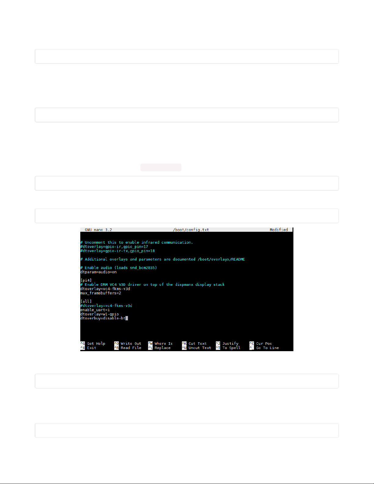
following command or similar to edit /boot/config.txt
sudo nano /boot/config.txt
Add the following line at the very bottom:
dtoverlay=disable-bt
Press CTRL-O to write the file and CTRL-X to exit the nano editor. When you have finished you should
reboot the system with
sudo reboot
Testing the Python App
After you have rebooted the system issue the following command to start up the Python Flask app that
will serve our webpage.
sudo python3 /home/pi/qtpyir/ir_app.py
© Adafruit Industries https://learn.adafruit.com/iot-ir-remote-using-raspberry-pi-zero-w-and-qtpy-hat Page 32 of 41
Page 33
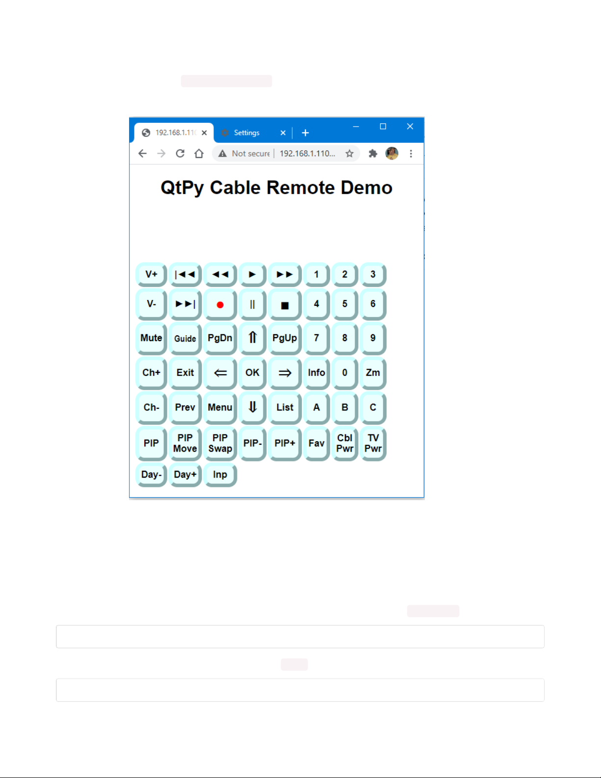
Earlier we had to determine the IP address of our Raspberry Pi Zero W on our local Wi-Fi network. You
should now call up a browser on your PC and navigate to that IP address. For example, when I was
testing, my IP address was http://192.168.1.110/
You should then see a page pop-up that looks like this:
At this point the webpage will not do anything because it is designed to communicate with the QT Py Hat
but at least we know that the web service is working. The command we issued however is only
temporary. We need a way to run that command at the start of every reboot and to keep the program
running in the background continuously.
To terminate the app that we just launched so that we can do some other things, press CTRL-C on the
command line. That will terminate the process.
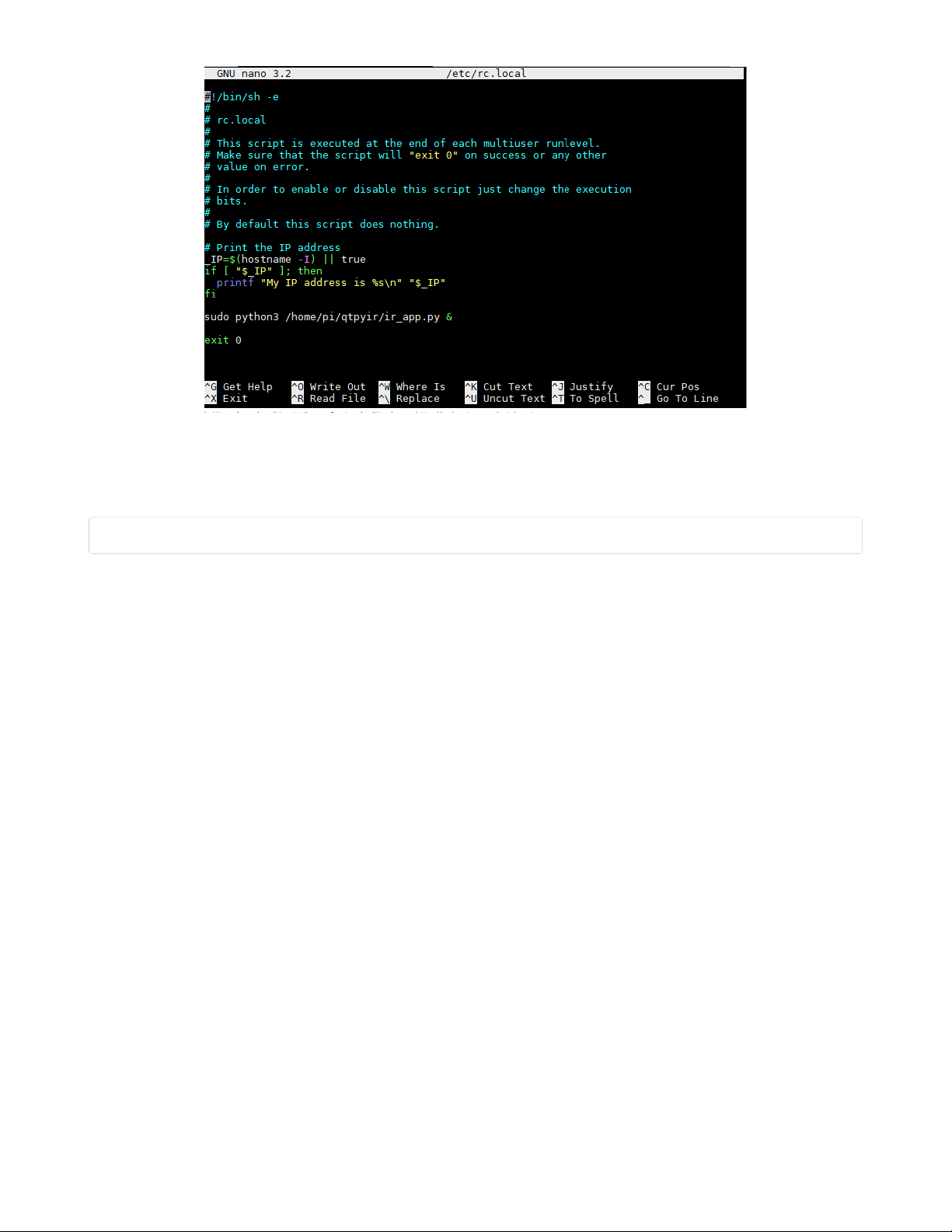
To make the app run automatically on each reboot we are going to edit the /etc/rc.local file as follows.
sudo nano /etc/rc.local
At the bottom of the file above the line that says exit 0 add the following text.
sudo python3 /home/pi/qtpyir/ir_app.py &
© Adafruit Industries https://learn.adafruit.com/iot-ir-remote-using-raspberry-pi-zero-w-and-qtpy-hat Page 33 of 41
Page 34
Note that this is the same command that we used to initialize the server app when we tested it a moment
ago except we have added an "&" at the end. This tells the program to run in the background and release
control back to the command line. Now save the file with CTRL-O and exit with CTRL-X then reboot your
system with
sudo reboot
After the system is rebooted, try pointing your browser at the IP address again and make sure that the
webpage serves properly.
© Adafruit Industries https://learn.adafruit.com/iot-ir-remote-using-raspberry-pi-zero-w-and-qtpy-hat Page 34 of 41
Page 35
Final Configuration Steps
It's now time to put it all together and test it. Unplug the power USB cables from both the Raspberry Pi
Zero W and the QT Py Hat. Carefully connect the two boards together making sure that the 40 pins line
up exactly. It could be easy to get off by one set of pins or to bend a pin so be careful.
Connect a USB power cable to the Raspberry Pi and connect the QT Py Hat to your PC using a USB C
cable for uploading programs. NOTE: Under normal operation, it is not necessary to have the USB C cable
connected to the QT Py. The entire system can be powered through the Raspberry Pi. However, for now
we do need it connected to upload software.
Find the program arduino_files/echo and upload it to the QT Py board. This program will monitor data
coming from your Raspberry Pi over the UART and echo it to your serial monitor. Upload the program and
open your serial monitor. Make sure that you set the baud rate to 19200.
Again on your PC use a browser and navigate to the IP address of your Raspberry Pi. As we mentioned
earlier on my system the IP address was http://192.168.1.110/
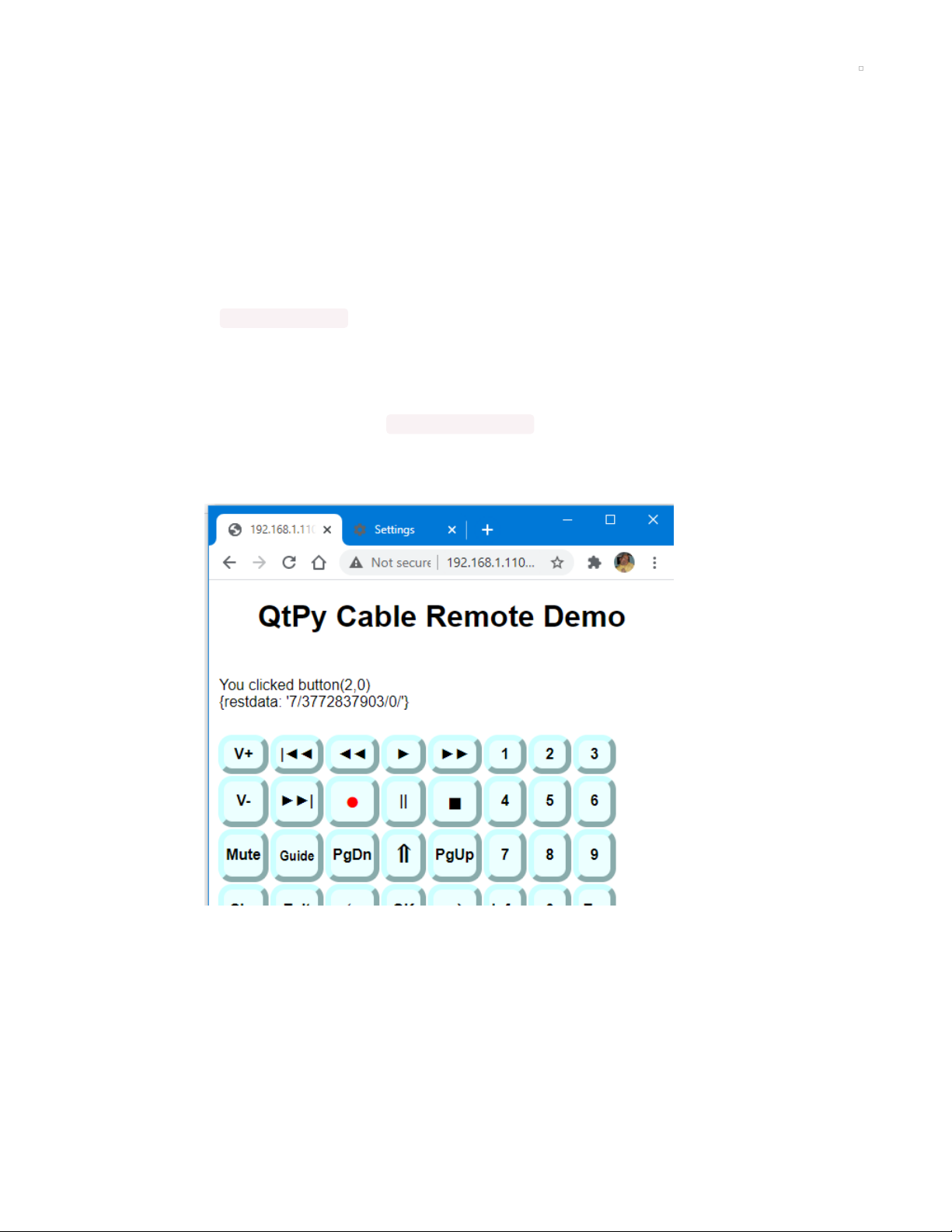
You should see the simulated remote control buttons pop up just like we did in the test earlier. This time
try clicking on one of the buttons. Here's what we saw when we clicked on the "Mute" button.
This tells us the row and column of the button that we clicked (the numbering system starts with zero)
then it also tells us the data that was sent to the REST API that we have created. The "7" means protocol
number 7 which is the NECx protocol if you remember from our previous test. The number "3772837903"
is the decimal representation of that 32-bit hexadecimal value that we found when we tested the mute
button on my TV which was E0E0F00F. (Don't worry we are not going to make you convert 32-bit hex
numbers into decimal numbers.) The third item is "0" because the NECx protocol doesn't need any
additional data. This string of digits and slashes is the string of data that was sent over the UART channel
from the Raspberry Pi to the QT Py board attached to your hat.
© Adafruit Industries https://learn.adafruit.com/iot-ir-remote-using-raspberry-pi-zero-w-and-qtpy-hat Page 35 of 41
Page 36

Look at the serial monitor on your Arduino IDE. It should be echoing that same stream of data that is
receiving from your Raspberry Pi. Ours looks like this:
Echoing serial port
7/3772837903/0/
If you happen to have a Samsung TV or a cable box from Spectrum Cable especially if it was a Spectrum
system that was formerly owned by Bright House Cable, then you might be lucky enough to have your
system already configured because that's what I have. But the likelihood of that is pretty slim. If you want
to try it out, find a program arduino_files/qtpy_ir_remote and upload it to the QT Py. Then when you click on
one of the buttons of your webpage remote, it should transmit the proper signals to your TV or cable DVR
box.
Chances are that's not the case. We're going to have to customize things to your particular TV and cable
system. Unfortunately, our software is not yet sophisticated enough to simply record the IR signals from
your existing remote control. We are working on it, but it's not yet ready. Were going to have to do this the
hard way.
Programming Custom IR Codes
Upload the program arduino_files/dumpFreq to the QT Py and open a serial monitor with a baud rate of
9600. We are going to test each of the buttons on your remote control and write down the protocol
number, the IR code, and any additional information about that function. Then we will modify a JavaScript
file to put these new codes into the system. Let's look at the JavaScript file first. On your Raspberry Pi, we
need to edit the /home/pi/qtpyir/static/codes.js file. No need to use the Linux editors if you have set up a
samba server. You can simply go to \\raspberrypi\userpi\qtpyir\static\codes.js and edit it using your favorite
text editor such as Notepad or Notepad++. Here are the first few lines of that file.
var PageTitle="QtPy Cable Remote Demo";
var Button= [//object containing all buttons
[//object containing row 0
[7,0xe0e0e01f,0, "V+",187],//Object containing button 1
[5,0x37c906,0, "|◄◄",74],//jump back "J"
[5,0x37291a,0, "◄◄",36],//rewind
[5,0x37990c,0, "►",32],//play
[5,0x36293a,0, "►►",35],//fast-forward
[5,0x36113d,0, "1",49],
[5,0x37111d,0, "2",50],
[5,0x36912d,0, "3",51]
],
[//row 1
[7,0xe0e0d02f,0, "V-",189],
[5,0x36b129,0, "►►|",78],//live "N"
[5,0x375914,0, "<span class='Red Big'>●</span>",82],//record "R"
[5,0x374117,0, "||",80],
[5,0x365934,0, "<span class='Big'>■</span>",83],//Stop
[5,0x37910d,0, "4",52],
[5,0x365135,0, "5",53],
[5,0x375115,0, "6",54]
],
[//row 2
The first line defines the text that appears at the top of your webpage.
© Adafruit Industries https://learn.adafruit.com/iot-ir-remote-using-raspberry-pi-zero-w-and-qtpy-hat Page 36 of 41
Page 37

Then we define all of the necessary information for each of the buttons displayed. Square brackets
enclose the entire button array definition. There are also brackets enclosing each row. And then each
button is defined within a set of brackets containing five values. The first button that appears in the
leftmost position of the top row is the "Volume Up" button. Let's talk about each of the data items.
The first one is the protocol number which is 7. The second item is the hexadecimal code for that
particular function. Notice that we prefix the value with "0x" to let it know that this is a hex number. There
is a third value which is in this case 0. We will talk more about when that might be a different value. The
fourth item is the text that will be displayed on the button. In this case, it is the "Volume Up" button so we
simply chose the text "V+" as you can see for some of the other buttons we used special characters.
The final value is the keyboard scan code number for that particular button. In addition to being able to
click on the buttons to activate the remote, you can also use keypresses. The code 187 is the code for the
"+" key. Actually is the code for the "=" key and a "+" is the shifted version of that. But the program ignores
the shift key and when you press + it returns code 187. Here is a reference for keyboard scan codes in
JavaScript and it allows you to test different keys to see what the code is.
https://www.cambiaresearch.com/articles/15/javascript-char-codes-key-codes (https://adafru.it/RFd)
You should now upload arduino_files/dumpFreq to the QT Py and open the serial monitor at 9600 baud.
Point your remote at the receiver chips on the Hat and write down the protocol number, the code, and the
address for each function of your remote. Then edit those values into the codes.js file.
The file we have provided you is just a template. You can add and remove buttons and rearrange them
however you want. You can label them however you want. Note that the text displayed on each button
can be any HTML information including tags like <span>, CSS information, or any other HTML tags.
Some of the special characters that we use are a bit undersized so we created a special class called "Big"
which makes the text bigger. We also included a class called "Red" which turns the text red. We use both
"Red" and "Big" classes on the record button to make a bigger red button.
Some protocols have more than just a protocol number and a 32-bit code. For example, there is
something called a Pioneer protocol which is the same as the NEC protocol #1 except that it uses a 40
kHz modulation instead of the standard 38 kHz modulation so in that case, you might encode your data
something like this.
[1,0x1234abcd,40, "V+",187]
By the way that's just a made-up code. It doesn't really do anything that we know of. Another example is
the Samsung36 protocol that is used by some Samsung Blu-ray players. It is a 36 protocol consisting of a
20-bit code followed by a 16-bit address. The code to stop my Blu-ray player would look like this.
[8,0xc837,0x0400, "<span class='Big'>■</span>",83],//Stop
We realize all of this is very confusing and complicated but we just don't have the software ready for a
traditional "learning remote" kind of function where you simply press the button on your existing remote
to record the data. We are working on it but it is very complicated.
Complete details of all of the protocols used by IRLib2 can be found in the extensive documentation in
your arduino/libraries/IRLib2/manuals folder. The documentation is available in .docx, PDF, and EPUB
© Adafruit Industries https://learn.adafruit.com/iot-ir-remote-using-raspberry-pi-zero-w-and-qtpy-hat Page 37 of 41
Page 38

format. Check out section "1.4 Protocol Details" for more information about the protocols supported by
IRLib2.
What If It Does Not Decode?
Sometimes the dumpFreq program doesn't recognize your code. If it happens to be about 56-57 kHz
frequency there's a good chance it is the "Panasonic Old" protocol. The codes of protocol 5 that we've
already included might work.
The arduino_files folder also contains programs called dump and freq which separate the regular
decoding and frequency detection into two different parts. It also provides more detailed information
which might be useful for reverse-engineering the protocol.
There is an extensive appendix to the IRLib2 on how to implement your own protocols. It may be that we
just cannot support your particular device.
Final Steps
When you've recorded all the codes for your devices and edited codes.js then load the program
arduino_files/qtpy_ir_remote . You can test out your newly programmed codes. Note that after editing
codes.js , reloading the webpage doesn't always cause a new copy of codes.js to be reloaded. You may
need to clear your browser cache and reload the page. Using Google Chrome press CTRL-SHIFT-DELETE
and then make sure that only "Cached images and files" is checked. Then click on "Clear Data" and
refresh the webpage. That will ensure the latest copy of all of your codes gets loaded.
Once you have all of your codes programmed and working, you can disconnect the USB C cable from the
QT Py and power the device solely through the Raspberry Pi.
Operating the Device
Place your device in a convenient location with the IR LED's pointed at your TV and cable box or other
devices. Call up the webpage at your IP address for your Raspberry Pi.
Not only can you click on the buttons on the webpage, you can also use keypresses. For example, we
have assigned "G" for "Guide" and "L" for "List". To see which keypresses activate which buttons you can
press the "Escape" key on your keyboard. The labels on the buttons will display what keypresses you
have assigned to each function. By pressing "Escape" again it will toggle back to the normal labels.
This keyboard function capability is especially useful as an assistive technology device. For example you
can use speech recognition software such as Dragon NaturallySpeaking or Windows 10 built in voice
control to use keypresses and arrow keys to navigate your cable or Blu-ray menus easily. If you've not
already done so, see the demonstration video on the first page of this tutorial.
© Adafruit Industries https://learn.adafruit.com/iot-ir-remote-using-raspberry-pi-zero-w-and-qtpy-hat Page 38 of 41
Page 39

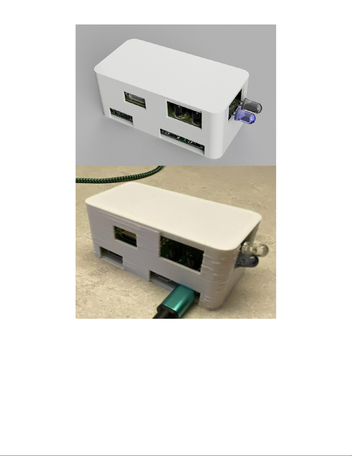
3D Printed Case
As an option we have included STL files for a 3D printed case. They are available in the "CAD_files" folder
of the GitHub repository you've already downloaded.
Disconnect any USB cords you have attached. Drop the assembly into the bottom part of the case. Snap
fit the lid on top.
© Adafruit Industries https://learn.adafruit.com/iot-ir-remote-using-raspberry-pi-zero-w-and-qtpy-hat Page 39 of 41
Page 40
© Adafruit Industries https://learn.adafruit.com/iot-ir-remote-using-raspberry-pi-zero-w-and-qtpy-hat Page 40 of 41
Page 41

© Adafruit Industries Last Updated: 2021-04-30 02:30:46 PM EDT Page 41 of 41
 Loading...