

Page 1
Adafruit HTU21D-F Temperature & Humidity Sensor
Created by lady ada
Last updated on 2021-04-14 05:22:35 PM EDT
Page 2

2
3
6
7
7
8
8
8
9
10
10
11
12
13
13
14
15
16
16
17
18
19
19
19
20
Guide Contents
Guide Contents
Overview
Pinouts
Power Pins:
I2C Logic pins:
Assembly
Prepare the header strip:
Add the breakout board:
And Solder!
Wiring & Test
Download Adafruit_HTU21DF
Load Demo
Library Reference
Python & CircuitPython
CircuitPython MicroController Wiring
Python Computer Wiring
CircuitPython Installation of HTU21D Library
Python Installation of HTU21D Library
CircuitPython & Python Usage
Full Example Code
Python Docs
Downloads
Files & Datasheets
Schematic and Fab Print for STEMMA QT Version
Schematic and Fab Print for Original Version
© Adafruit Industries https://learn.adafruit.com/adafruit-htu21d-f-temperature-humidity-sensor Page 2 of 22
Page 3
Overview
It's summer and you're sweating and your hair's all frizzy and all you really want to know is why the
weatherman said this morning that today's relative humidity would max out at a perfectly reasonable 52%
when it feels more like 77%. Enter the HTU21D-F Temperature + Humidity Sensor - the best way to prove
the weatherman wrong!
This I2C digital humidity sensor is an accurate and intelligent alternative to the much simpler Humidity and
Temperature Sensor - SHT15 Breakout (http://adafru.it/1638) It has a typical accuracy of ±2% with an
operating range that's optimized from 5% to 95% RH. Operation outside this range is still possible - just
the accuracy might drop a bit. The temperature output has an accuracy of ±1°C from -30~90°C. If you're
© Adafruit Industries https://learn.adafruit.com/adafruit-htu21d-f-temperature-humidity-sensor Page 3 of 22
Page 4
looking to measure temperature more accurately, we recommend the MCP9808 High Accuracy I2C
Temperature Sensor Breakout Board. (http://adafru.it/1782)
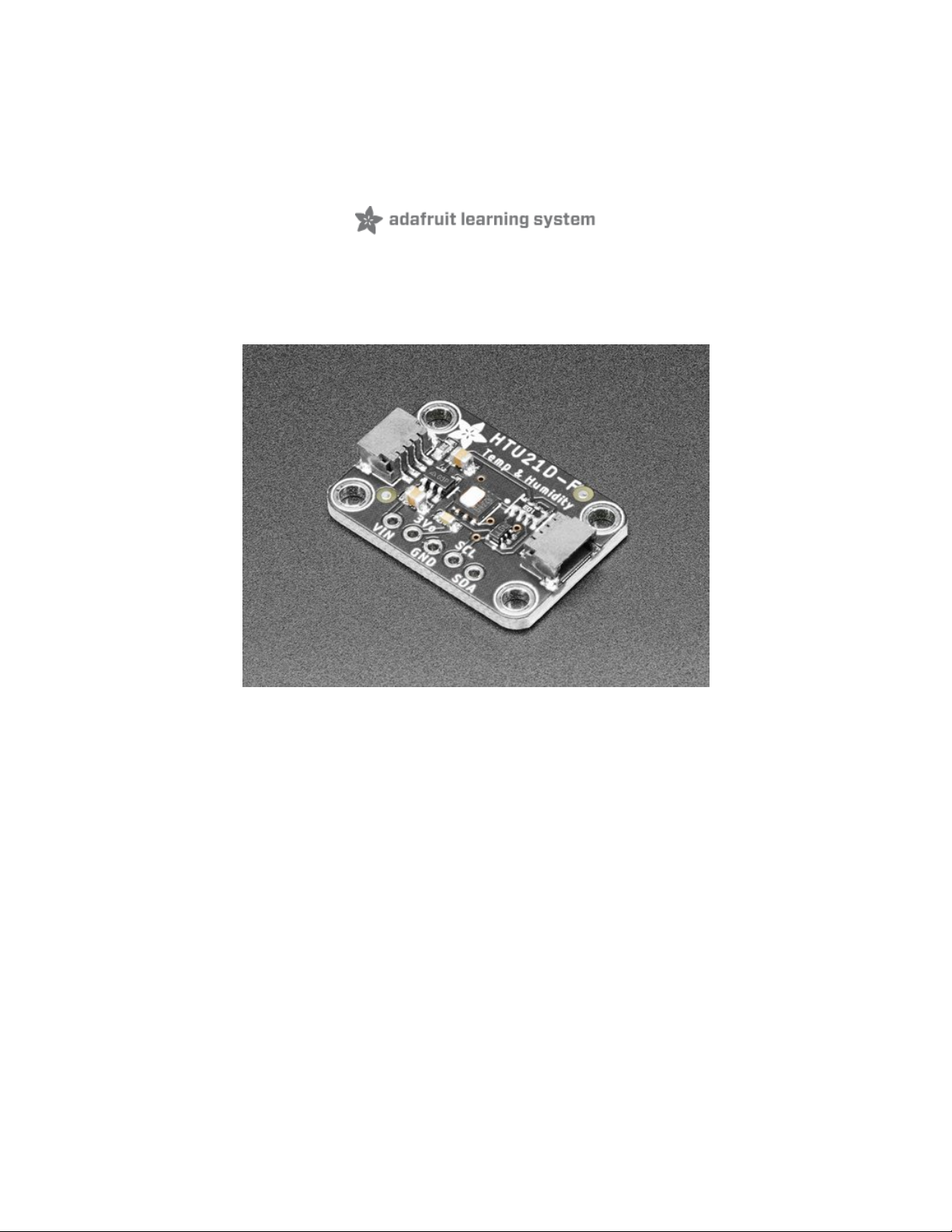
Such a lovely chip - so we spun up a breakout board that includes the Filtered version (the white bit of
plastic which is a PTFE filter to keep the sensor clean), a 3.3V regulator and I2C level shifting circuitry. This
lets you use it safely with any kind of microcontroller with 3.3V-5V power or logic.
To get you going fast, we spun up a custom made PCB in the STEMMA QT form
factor (https://adafru.it/LBQ), making them easy to interface with. The STEMMA QT
connectors (https://adafru.it/JqB) on either side are compatible with the SparkFun
Qwiic (https://adafru.it/Fpw) I2C connectors. This allows you to make solderless connections between
© Adafruit Industries https://learn.adafruit.com/adafruit-htu21d-f-temperature-humidity-sensor Page 4 of 22
Page 5

your development board and the HTU21Ds or to chain them with a wide range of other sensors and
accessories using a compatible cable (https://adafru.it/JnB). QT Cable is not included, but we have a
variety in the shop (https://adafru.it/JnB).
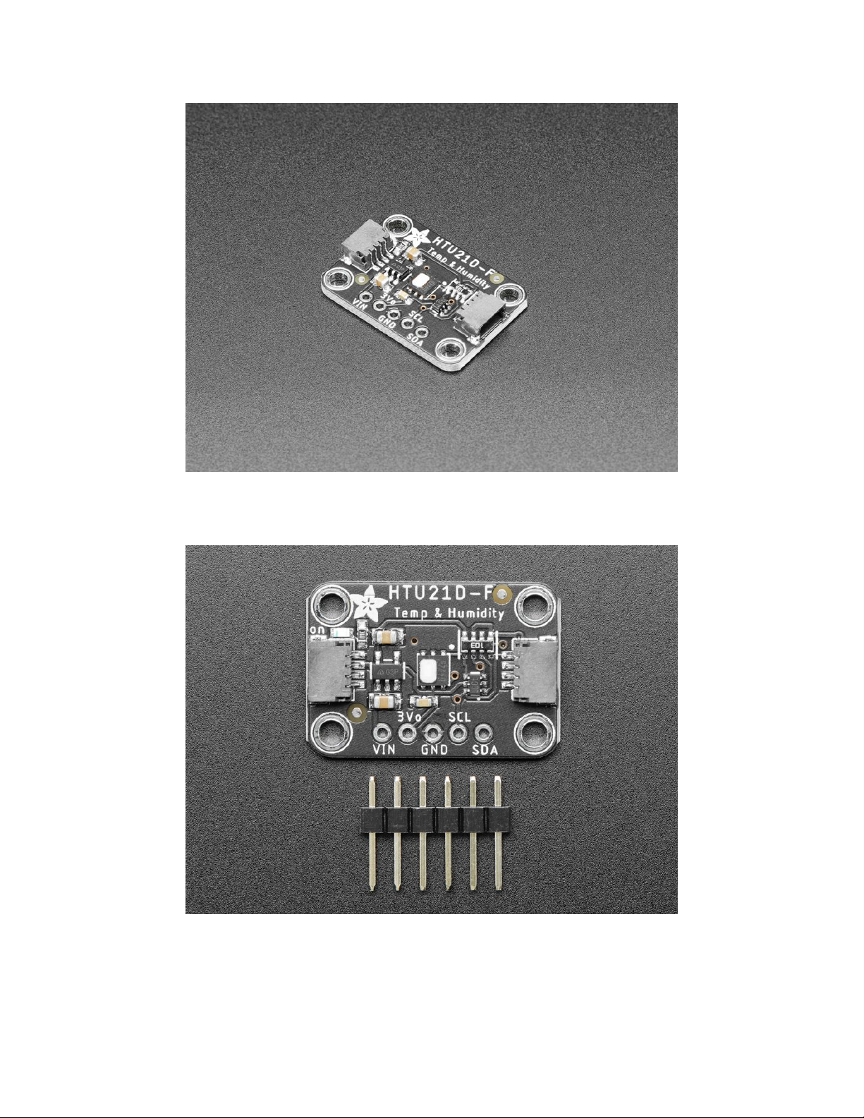
Each order comes with one fully assembled and tested PCB breakout and a small piece of header. You'll
need to solder the header onto the PCB but it's fairly easy and takes only a few minutes even for a
beginner.
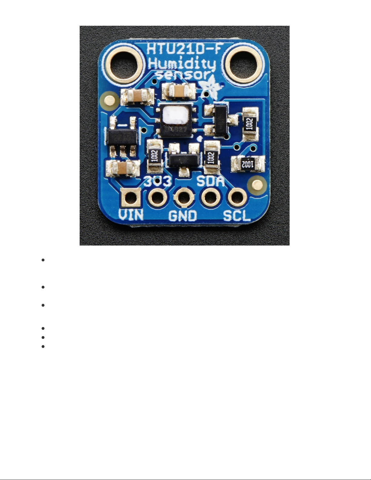
There are two versions of this board - the STEMMA QT version shown above, and the original
header-only version shown below. Code works the same on both!
© Adafruit Industries https://learn.adafruit.com/adafruit-htu21d-f-temperature-humidity-sensor Page 5 of 22
Page 6
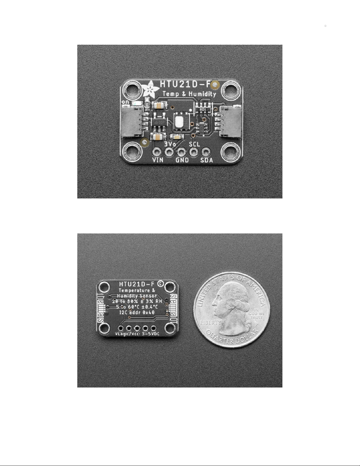
Pinouts
The HTU21D-F is a I2C sensor. That means it uses the two I2C data/clock wires available on most
microcontrollers, and can share those pins with other sensors as long as they don't have an address
collision. For future reference, the I2C address is 0x40 and you
can't
change it!
© Adafruit Industries https://learn.adafruit.com/adafruit-htu21d-f-temperature-humidity-sensor Page 6 of 22
Page 7
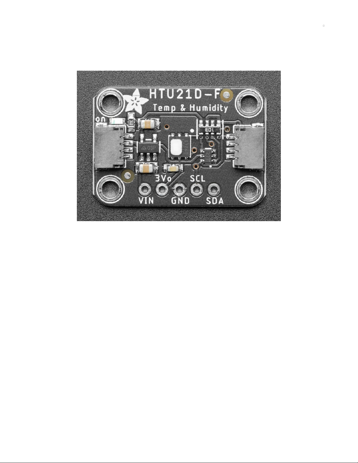
Power Pins:
Vin - this is the power pin. Since the chip uses 3 VDC, we have included a voltage regulator on board
that will take 3-5VDC and safely convert it down. To power the board, give it the same power as the
logic level of your microcontroller - e.g. for a 5V micro like Arduino, use 5V
3Vo (3v3 on original version) - this is the 3.3V output from the voltage regulator, you can grab up to
100mA from this if you like
GND - common ground for power and logic
I2C Logic pins:
SCL - I2C clock pin, connect to your microcontrollers I2C clock line.
SDA - I2C data pin, connect to your microcontrollers I2C data line.
STEMMA QT (https://adafru.it/Ft4) - These connectors allow you to connect to development boards
with STEMMA QT connectors, or to other things, with various associated
accessories (https://adafru.it/Ft6).
© Adafruit Industries https://learn.adafruit.com/adafruit-htu21d-f-temperature-humidity-sensor Page 7 of 22
Page 8

Assembly
Prepare the header strip:
Cut the strip to length if necessary. It will be easier to solder if
you insert it into a breadboard - long pins down
Add the breakout board:
Place the breakout board over the pins so that the short pins
poke through the breakout pads
© Adafruit Industries https://learn.adafruit.com/adafruit-htu21d-f-temperature-humidity-sensor Page 8 of 22
Page 9

And Solder!
Be sure to solder all pins for reliable electrical contact.
(For tips on soldering, be sure to check out our Guide to
Excellent Soldering
(https://adafru.it/aTk)
).
You're done! Check your solder joints visually and continue
onto the next steps
© Adafruit Industries https://learn.adafruit.com/adafruit-htu21d-f-temperature-humidity-sensor Page 9 of 22
Page 10

Wiring & Test
You can easily wire this breakout to any microcontroller, we'll be using an Arduino. For another kind of
microcontroller, just make sure it has I2C, then port the code - its pretty simple stuff!
Connect Vin to the power supply, 3-5V is fine. (red wire
on STEMMA QT version) Use the same voltage that the
microcontroller logic is based off of. For most Arduinos,
that is 5V
Connect GND to common power/data ground (black
wire on STEMMA QT version)
Connect the SCL pin to the I2C clock SCL pin on your
Arduino. (yellow wire on STEMMA QT version) On an
UNO & '328 based Arduino, this is also known as A5, on
a Mega it is also known as digital 21 and on a
Leonardo/Micro, digital 3
Connect the SDA pin to the I2C data SDA pin on your
Arduino. (blue wire on STEMMA QT verison) On an
UNO & '328 based Arduino, this is also known as A4, on
a Mega it is also known as digital 20 and on a
Leonardo/Micro, digital 2
The HTU21D-F has a default I2C address of 0x40 and cannot
be changed!
Download Adafruit_HTU21DF
To begin reading sensor data, you will need to download the Adafruit HTU21DF library from the Arduino
library manager.
Open up the Arduino library manager:
© Adafruit Industries https://learn.adafruit.com/adafruit-htu21d-f-temperature-humidity-sensor Page 10 of 22
Page 11

Search for the Adafruit HTU21DF library and install it
We also have a great tutorial on Arduino library installation at:
http://learn.adafruit.com/adafruit-all-about-arduino-libraries-install-use (https://adafru.it/aYM)
Load Demo
Open up File->Examples->Adafruit_HTU21DF->HTU21DFtest and upload to your Arduino wired up to the
sensor
Thats it! Now open up the serial terminal window at 9600 speed to begin the test.
© Adafruit Industries https://learn.adafruit.com/adafruit-htu21d-f-temperature-humidity-sensor Page 11 of 22
Page 12

You can try breathing on the sensor to increase the humidity. The sensor reacts very fast!
Library Reference
The library we have is simple and easy to use
You can create the Adafruit_HTU21DF object with:
Adafruit_HTU21DF htu = Adafruit_HTU21DF()
There are no pins to set since you must use the I2C bus!
Then initialize the sensor with:
htu.begin()
this function returns True if the sensor was found and responded correctly and False if it was not found
Once initialized, you can query the temperature in °C with
htu.readTemperature()
Which will return floating point (decimal + fractional) temperature. You can convert to Fahrenheit by
multiplying by 1.8 and adding 32 as you have learned in grade school!
Reading the humidity is equally simple. Call
htu.readHumidity()
to read the humidity also as a floating point value between 0 and 100 (this reads % humidity)
© Adafruit Industries https://learn.adafruit.com/adafruit-htu21d-f-temperature-humidity-sensor Page 12 of 22
Page 13

Python & CircuitPython
It's easy to use the HTU21D-F sensor with Python or CircuitPython and the Adafruit CircuitPython
HTU21D (https://adafru.it/CDn) module. This module allows you to easily write Python code that reads the
humidity and temperature from the sensor.
You can use this sensor with any CircuitPython microcontroller board or with a computer that has GPIO
and Python thanks to Adafruit_Blinka, our CircuitPython-for-Python compatibility
library (https://adafru.it/BSN).
CircuitPython MicroController Wiring
First wire up a HTU21D-F to your board exactly as shown on the previous pages for Arduino. Here's an
example of wiring a Feather M0 Express to the sensor with I2C:
© Adafruit Industries https://learn.adafruit.com/adafruit-htu21d-f-temperature-humidity-sensor Page 13 of 22
Page 14

Board 3V3 to sensor VIN (red wire on STEMMA QT
version)
Board GND to sensor GND (black wire on STEMMA QT
version)
Board SCL to sensor SCL (yellow wire on STEMMA QT
version)
Board SDA to sensor SDA (blue wire on STEMMA QT
version)
Python Computer Wiring
© Adafruit Industries https://learn.adafruit.com/adafruit-htu21d-f-temperature-humidity-sensor Page 14 of 22
Page 15

Since there's
dozens
of Linux computers/boards you can use we will show wiring for Raspberry Pi. For
other platforms, please visit the guide for CircuitPython on Linux to see whether your platform is
supported (https://adafru.it/BSN).
Here's the Raspberry Pi wired with I2C:
Pi GND to sensor GND (black wire on STEMMA QT
version)
Pi 3V3 to sensor VIN (red wire on STEMMA QT version)
Pi SDA to sensor SDA (blue wire on STEMMA QT
version)
Pi SCL to sensor SCL (yellow wire on STEMMA QT
version)
CircuitPython Installation of HTU21D Library
You'll need to install the Adafruit CircuitPython HTU21D (https://adafru.it/CDn) library on your
CircuitPython board.
First make sure you are running the latest version of Adafruit CircuitPython (https://adafru.it/Amd) for your
board.
Next you'll need to install the necessary libraries to use the hardware--carefully follow the steps to find
© Adafruit Industries https://learn.adafruit.com/adafruit-htu21d-f-temperature-humidity-sensor Page 15 of 22
Page 16

and install these libraries from Adafruit's CircuitPython library bundle (https://adafru.it/uap). Our
CircuitPython starter guide has a great page on how to install the library bundle (https://adafru.it/ABU).
For non-express boards like the Trinket M0 or Gemma M0, you'll need to manually install the necessary
libraries from the bundle:
adafruit_htu21d.mpy
adafruit_bus_device
Before continuing make sure your board's lib folder or root filesystem has the adafruit_htu21d.mpy, and
adafruit_bus_device files and folders copied over.
Next connect to the board's serial REPL (https://adafru.it/Awz) so you are at the CircuitPython >>> prompt.
Python Installation of HTU21D Library
You'll need to install the Adafruit_Blinka library that provides the CircuitPython support in Python. This
may also require enabling I2C on your platform and verifying you are running Python 3. Since each
platform is a little different, and Linux changes often, please visit the CircuitPython on Linux guide to get
your computer ready (https://adafru.it/BSN)!
Once that's done, from your command line run the following command:
sudo pip3 install adafruit-circuitpython-htu21d
If your default Python is version 3 you may need to run 'pip' instead. Just make sure you aren't trying to
use CircuitPython on Python 2.x, it isn't supported!
CircuitPython & Python Usage
To demonstrate the usage of the sensor we'll initialize it and read the humidity and temperature values
from the board's Python REPL.
Run the following code to import the necessary modules and initialize the I2C connection with the sensor:
import time
import board
import busio
from adafruit_htu21d import HTU21D
# Create library object using our Bus I2C port
i2c = busio.I2C(board.SCL, board.SDA)
sensor = HTU21D(i2c)
Now you're ready to read values from the sensor using any of these properties:
temperature - the temperature in degrees Celsius.
relative_humidity - the relative humidity in percent.
For example to print temperature:
print("\nTemperature: %0.1f C" % sensor.temperature)
© Adafruit Industries https://learn.adafruit.com/adafruit-htu21d-f-temperature-humidity-sensor Page 16 of 22
Page 17

That's all there is to using the HTU21D-F sensor with CircuitPython!
Full Example Code
Temporarily unable to load content:
© Adafruit Industries https://learn.adafruit.com/adafruit-htu21d-f-temperature-humidity-sensor Page 17 of 22
Page 18

Python Docs
Python Docs (https://adafru.it/CDF)
© Adafruit Industries https://learn.adafruit.com/adafruit-htu21d-f-temperature-humidity-sensor Page 18 of 22
Page 19

Downloads
Files & Datasheets
Datasheet for the HTU21D-F (https://adafru.it/dKR) (the -F part is for the PTFE Filter, which is the white
insert on top of the sensor)
Fritzing object in Adafruit Fritzing library (https://adafru.it/aP3)
EagleCAD PCB files in GitHub (https://adafru.it/r5F)
K&R Smith calibration notes (https://adafru.it/BfU)
Schematic and Fab Print for STEMMA QT Version
© Adafruit Industries https://learn.adafruit.com/adafruit-htu21d-f-temperature-humidity-sensor Page 19 of 22
Page 20

Schematic and Fab Print for Original Version
© Adafruit Industries https://learn.adafruit.com/adafruit-htu21d-f-temperature-humidity-sensor Page 20 of 22
Page 21

© Adafruit Industries https://learn.adafruit.com/adafruit-htu21d-f-temperature-humidity-sensor Page 21 of 22
Page 22

© Adafruit Industries Last Updated: 2021-04-14 05:22:35 PM EDT Page 22 of 22
 Loading...