

Page 1

Adafruit GPIO Expander Bonnet for Raspberry Pi
Created by Kattni Rembor
Last updated on 2020-06-03 04:59:51 PM EDT
Page 2

Overview
The Raspberry Pi is an amazing single board computer - and one of the best parts is that GPIO connector! 40 pins of
digital goodness you can twiddle to control LEDs, sensors, buttons, radios, displays - just about any device you can
imagine. This Adafruit GPIO Expander Bonnet will give you
even more
digital deliciousness - 16 more digital
input/output pins are yours for any desire you have. The outputs are grouped into two 16-pin connectors that have a
matching ground pin. You can set each pin to be a digital output (high or low) or as an input, with an internal pull-up if
you like!
Simply pop the Bonnet on top of your Pi, the circuitry connects to the SDA/SCL I2C pins for control. The MCP23017
chip converts our Python commands to pin instructions.
© Adafruit Industries https://learn.adafruit.com/gpio-expander-bonnet Page 3 of 17
Page 3

When used as an output, each pin can supply up to 20mA (current clamped) - so you can drive LEDs directly. The
datasheet recommends you keep the total current draw to under 125mA for the whole chip. We set up the expander
chip for 5V logic by default (the I2C is level shifted so that's 3V logic). We did that so you can drive white, blue or green
LEDs that sometimes aren't too happy with 3.3V logic. Or, you can cut/solder a jumper to change it to 3.3V logic.
When used as an input, you can set up a pull-up resistor so buttons and switches don't need extra resistors - just wire
the pin to one side and ground to the other! There's interrupt capabilities on the chip, and two IRQ pins (INTA and
INTB) you can solder a wire to, if you want to have a quick way of telling if any of the GPIOs changed.
© Adafruit Industries https://learn.adafruit.com/gpio-expander-bonnet Page 4 of 17
Page 4

By soldering closed the address select jumpers, you can change the address from 0x20 up to 0x27. So, if you wanted
to, you could have up to 8 bonnets for 128 total GPIO.
Comes as an assembled and tested Bonnet with slim 2x20 header connector on the bottom. We provide 2 sets of 16-
pin IDC sockets, you can solder these in or leave them off for a slim setup. Use our CircuitPython library with Python 3
for fast and easy setup and configuration, you'll be running in under 5 minutes. (https://adafru.it/Boh)
© Adafruit Industries https://learn.adafruit.com/gpio-expander-bonnet Page 5 of 17
Page 5

Pinouts
This Bonnet provides you with a number of options. Let's take a look!
MCP23017 GPIO Expander Chip
The MCP23017 GPIO expander chip converts Python
code into pin instructions.
GPIO Expansion Headers
© Adafruit Industries https://learn.adafruit.com/gpio-expander-bonnet Page 6 of 17
Page 6

You can solder the included headers onto the Bonnet,
or leave them off for a slimmer setup.
The top section is GPB0 - header B.
The bottom set is GPA0 - header A.
The top row of each set of headers is ground.
The bottom row, numbered 0-7, is the 8 IO pins.
Address Select Jumpers
By soldering closed the address select jumpers, you
can change the address from 0x20 to 0x27. This allows
up to 8 bonnets for 128 total GPIO.
Interrupt Pins
© Adafruit Industries https://learn.adafruit.com/gpio-expander-bonnet Page 7 of 17
Page 7

The MCP23017 has interrupt capabilities. There are two
IRQ pins (INTA and INTB) you can solder a wire to, if
you want to have a quick way of telling if any of the
GPIO's changed.
3V/5V Jumper
This Bonnet defaults to using 5V. There is a jumper to
swap between 3V and 5V. If you want to change it to
3V, you can cut the trace between the top two pads,
and solder the bottom two pads.
© Adafruit Industries https://learn.adafruit.com/gpio-expander-bonnet Page 8 of 17
Page 8

Python Usage
Make sure you've installed the bonnet onto your single board Linux computer by plugging it in and then restarting.
You will need to have I2C set up and activated - here's how to do it for Raspberry Pi. (https://adafru.it/dEO)
Once that's done and the bonnet installed, board rebooted, you should be able to I2C scan to find the device with
something like sudo i2c-detect -y 1 (the number may be different on non-Raspi computers)
The default address for the bonnet is 0x20
Python Installation of MCP23017 Library
You can use this Bonnet with Python and Raspberry Pi thanks to Adafruit_Blinka, our CircuitPython-for-Python
compatibility library (https://adafru.it/BSN).
You'll need to install the Adafruit_Blinka library that provides the CircuitPython support in Python. This may also
require enabling I2C on your platform and verifying you are running Python 3. Since each platform is a little different,
and Linux changes often, please visit the CircuitPython on Linux guide to get your computer
ready (https://adafru.it/BSN)!
Once that's done, from your command line run the following command:
sudo pip3 install adafruit-circuitpython-mcp230xx
If your default Python is version 3 you may need to run 'pip' instead. Just make sure you aren't trying to use
CircuitPython on Python 2.x, it isn't supported!
Python Usage
To demonstrate the usage, we'll use Python code to read a button and light up an LED from the Python REPL.
Wire up the bonnet as follows:
LED anode through a resistor (220 to 4.7Kohm) to GPA0
LED cathode (short leg) to one of the GND pads (any)
One side of switch to GPA1
Other side of switch to one of the GND pads (any)
© Adafruit Industries https://learn.adafruit.com/gpio-expander-bonnet Page 9 of 17
Page 9

And start up Python3
First you'll need to import the necessary modules, initialize the I2C bus for your board, and create an instance of the
class.
import time
import board
import busio
import digitalio
from adafruit_mcp230xx.mcp23017 import MCP23017
# Initialize the I2C bus:
i2c = busio.I2C(board.SCL, board.SDA)
mcp = MCP23017(i2c) # MCP23017
Now you have the device called mcp , you can use that to 'create' DigitalInOut pins, by calling get_pin . The pins are
ordered 0-15. Pin #0 is GPA0, #1 is GPA1, #8 is GPB0, #15 is GPB7
pin0 = mcp.get_pin(0) # GPA0
pin1 = mcp.get_pin(1) # GPA1
Now you can treat these like regular digital inputs and outputs. Set GPA0 to be an output and level high voltage.
The LED should turn on!
# Setup pin0 as an output that's at a high logic level.
pin0.switch_to_output(value=True)
And set GPA1 to be an input with a pullup
# Setup pin1 as an input with a pull-up resistor enabled. Notice you can also
# use properties to change this state.
pin1.direction = digitalio.Direction.INPUT
pin1.pull = digitalio.Pull.UP
Finally we can have a loop where we read and write data to the pins
© Adafruit Industries https://learn.adafruit.com/gpio-expander-bonnet Page 10 of 17
Page 10
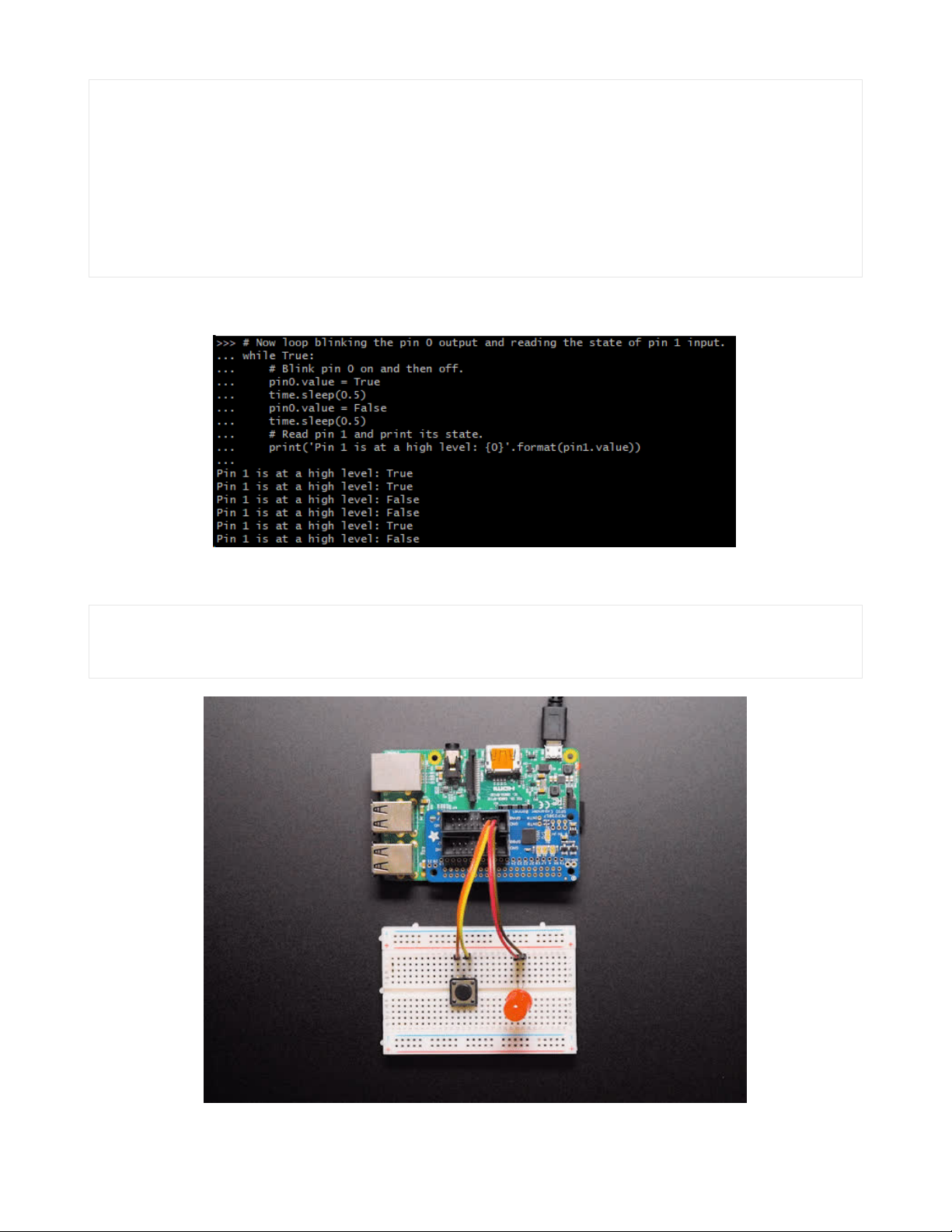
# Now loop blinking the pin 0 output and reading the state of pin 1 input.
while True:
# Blink pin 0 on and then off.
pin0.value = True
time.sleep(0.5)
pin0.value = False
time.sleep(0.5)
# Read pin 1 and print its state.
print('Pin 1 is at a high level: {0}'.format(pin1.value))
The LED should start blinking. You can also press the button to see the output change for the pin 1 value:
Type Control-C to quit. Then try this code that will light up the LED when the button is pressed:
# Now loop setting the LED when the button is pressed
while True:
pin0.value = not pin1.value
© Adafruit Industries https://learn.adafruit.com/gpio-expander-bonnet Page 11 of 17
Page 11

That's pretty much all you need to get started with the bonnet!
The fully commented example is here:
This full sketch uses the MCP23008 by default, change the "mcp = adafruit_mcp230xx.MCP23008" line to
the MCP23017 before running this on the bonnet!
© Adafruit Industries https://learn.adafruit.com/gpio-expander-bonnet Page 12 of 17
Page 12

# Simple demo of reading and writing the digital I/O of the MCP2300xx as if
# they were native CircuitPython digital inputs/outputs.
# Author: Tony DiCola
import time
import board
import busio
import digitalio
from adafruit_mcp230xx.mcp23008 import MCP23008
# from adafruit_mcp230xx.mcp23017 import MCP23017
# Initialize the I2C bus:
i2c = busio.I2C(board.SCL, board.SDA)
# Create an instance of either the MCP23008 or MCP23017 class depending on
# which chip you're using:
mcp = MCP23008(i2c) # MCP23008
# mcp = MCP23017(i2c) # MCP23017
# Optionally change the address of the device if you set any of the A0, A1, A2
# pins. Specify the new address with a keyword parameter:
# mcp = MCP23017(i2c, address=0x21) # MCP23017 w/ A0 set
# Now call the get_pin function to get an instance of a pin on the chip.
# This instance will act just like a digitalio.DigitalInOut class instance
# and has all the same properties and methods (except you can't set pull-down
# resistors, only pull-up!). For the MCP23008 you specify a pin number from 0
# to 7 for the GP0...GP7 pins. For the MCP23017 you specify a pin number from
# 0 to 15 for the GPIOA0...GPIOA7, GPIOB0...GPIOB7 pins (i.e. pin 12 is GPIOB4).
pin0 = mcp.get_pin(0)
pin1 = mcp.get_pin(1)
# Setup pin0 as an output that's at a high logic level.
pin0.switch_to_output(value=True)
# Setup pin1 as an input with a pull-up resistor enabled. Notice you can also
# use properties to change this state.
pin1.direction = digitalio.Direction.INPUT
pin1.pull = digitalio.Pull.UP
# Now loop blinking the pin 0 output and reading the state of pin 1 input.
while True:
# Blink pin 0 on and then off.
pin0.value = True
time.sleep(0.5)
pin0.value = False
time.sleep(0.5)
# Read pin 1 and print its state.
print("Pin 1 is at a high level: {0}".format(pin1.value))
We have more examples, including interrupt detection so you don't have to constantly query the pin values for
buttons. Visit https://github.com/adafruit/Adafruit_CircuitPython_MCP230xx/tree/master/examples (https://adafru.it/Edj)
to see all the examples
© Adafruit Industries https://learn.adafruit.com/gpio-expander-bonnet Page 13 of 17
Page 13

Some of the examples may be set up for an MCP23008 instead of MCP23017 so be sure to update the objection
creation at the top!
© Adafruit Industries https://learn.adafruit.com/gpio-expander-bonnet Page 14 of 17
Page 14

Python Docs
Python Docs (https://adafru.it/CMs)
© Adafruit Industries https://learn.adafruit.com/gpio-expander-bonnet Page 15 of 17
Page 15

Downloads
Files
MCP23017 GPIO Expander Datasheet (https://adafru.it/EcK)
Adafruit GPIO Expander Bonnet EagleCAD files on GitHub (https://adafru.it/EcL)
Fritzing object in our Fritzing repo (https://adafru.it/aP3)
Schematics and Fab Print
© Adafruit Industries https://learn.adafruit.com/gpio-expander-bonnet Page 16 of 17
Page 16

© Adafruit Industries Last Updated: 2020-06-03 04:59:51 PM EDT Page 17 of 17
 Loading...