

Page 1
Adafruit STM32F405 Feather Express
Created by lady ada
Last updated on 2021-03-26 10:58:29 AM EDT
Page 2

2
3
6
6
8
8
8
8
8
9
11
11
12
12
13
13
14
15
15
16
17
17
17
18
18
19
20
20
20
20
20
22
24
26
26
26
28
28
29
29
30
30
30
Guide Contents
Guide Contents
Overview
Pinouts
Power Pins
I2S Pins:
CAN Pins:
SD Card / SDIO Pins
BAT Pins
SWD Port
SPI Flash, STEMMA and NeoPixel
Assembly
Header Options!
Soldering in Plain Headers
Prepare the header strip:
Add the breakout board:
And Solder!
Soldering on Female Header
Tape In Place
Flip & Tack Solder
And Solder!
Power Management
Battery + USB Power
Power supplies
Measuring Battery
ENable pin
Alternative Power Options
DFU Bootloader Details
Enabling DFU bootloader mode
Check for USB Bootloader device
Programming Firmware
Windows
Mac (and Linux)
Arduino IDE Setup
Activate the Bootloader
Upload!
STM32duino Notes
MicroPython Setup
MicroPython Notes
CircuitPython Setup
CircuitPython Notes
Downloads
Files
Schematic & Fabrication Print
© Adafruit Industries https://learn.adafruit.com/adafruit-stm32f405-feather-express Page 2 of 31
Page 3
Overview
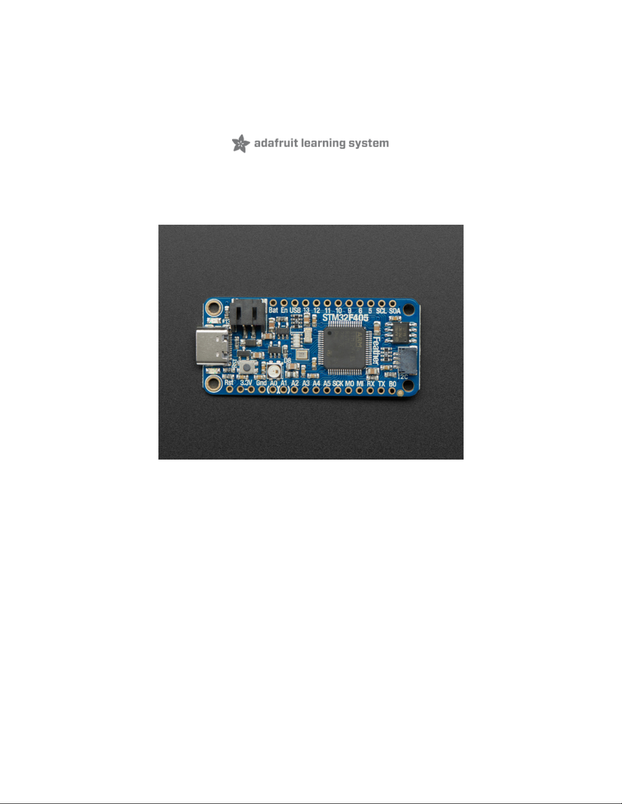
ST takes flight in this new Feather board. This STM32F405 Feather ( video (https://adafru.it/GD7)) runs CircuitPython at a blistering 168MHz – our
fastest CircuitPython board ever! We put a STEMMA QT / Qwiic port on the end, so you can really easily plug and play I2C sensors.
This Feather has lots of goodies:
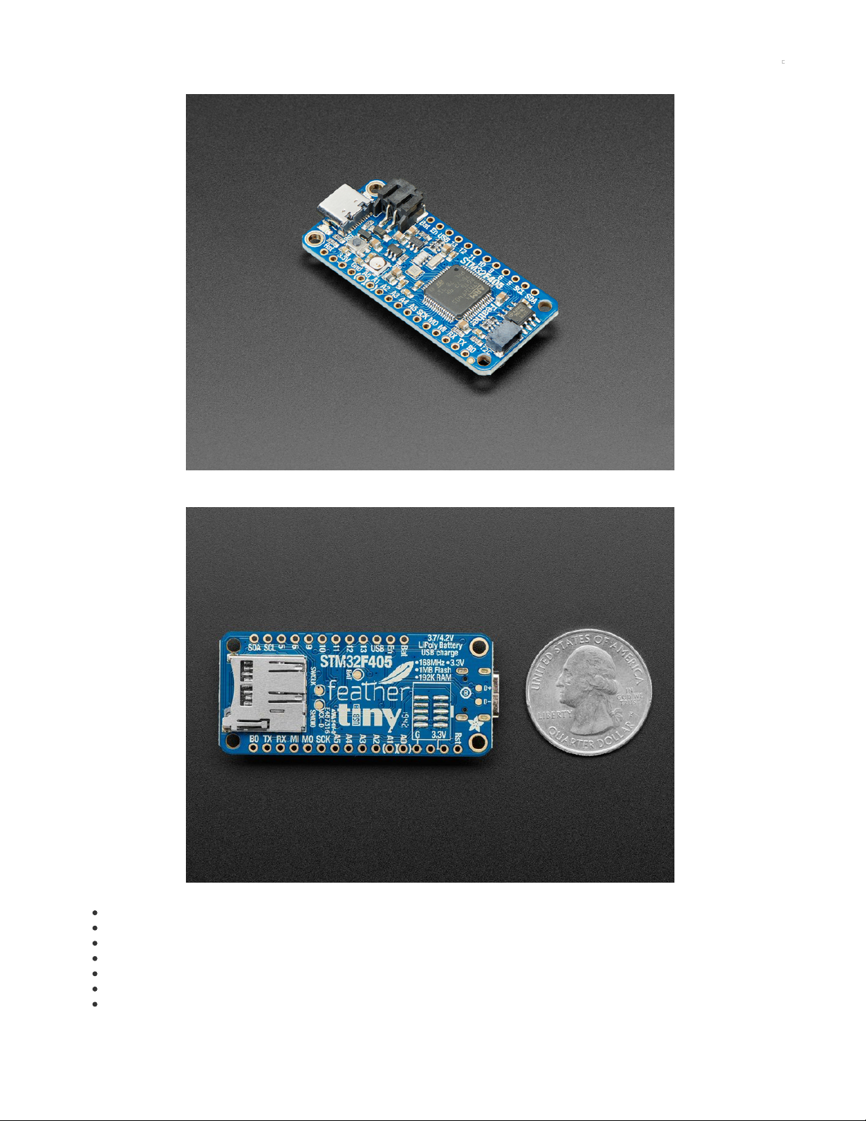
STM32F405 Cortex M4 with 1MB Flash, 168MHz speed
3.3V logic, but almost all pins are 5V compliant!
USB C power and data - our first USB C Feather!
LiPo connector and charger
SD socket on the bottom, connected to SDIO port
2 MB SPI Flash chip
Built in NeoPixel indicator
© Adafruit Industries https://learn.adafruit.com/adafruit-stm32f405-feather-express Page 3 of 31
Page 4
I2C, UART, GPIO, ADCs, DACs
Qwiic/STEMMA-QT connector for fast I2C connectivity
We use the built-in USB DFU bootloader to load firmware. It does
not
come with a UF2 bootloader.
With CircuitPython basics running on this board, it's fast to get all our drivers working, then use the built in plotter in Mu to instantly get sensor data
displaying within 3 minutes of unboxing.
You can use MicroPython, CircuitPython or Arduino IDE with this board, with some caveats.
CircuitPython support is under development. F4 family boards like this one are considered stable, and support common modules like digital
IO, analog IO, I2C, SPI, PWM, and displays. Some less-used modules may be missing compared to the SAMD-type Feathers - you can check
the exact list of supported modules on our documentation's Support Matrix (https://adafru.it/N2a).
Arduino is supported through STM32duino (https://adafru.it/GD8). There's no auto-reset bootloader support yet (https://adafru.it/GD9) so you
have to pull the BOOT0 pin high and manually reset before uploading. That said, STM32 support is really good, and we were able to run just
about every sketch we tried.
MicroPython support is very solid but Adafruit does not provide MicroPython libraries for sensors!
We tested this in Arduino STM32duino with all our FeatherWings and only the RFM69/RFM9x libraries did not work (they are very platform specific).
It's an extraordinarily fast Feather, and our first foray into STM32 - very exciting!
© Adafruit Industries https://learn.adafruit.com/adafruit-stm32f405-feather-express Page 4 of 31
Page 5
© Adafruit Industries https://learn.adafruit.com/adafruit-stm32f405-feather-express Page 5 of 31
Page 6
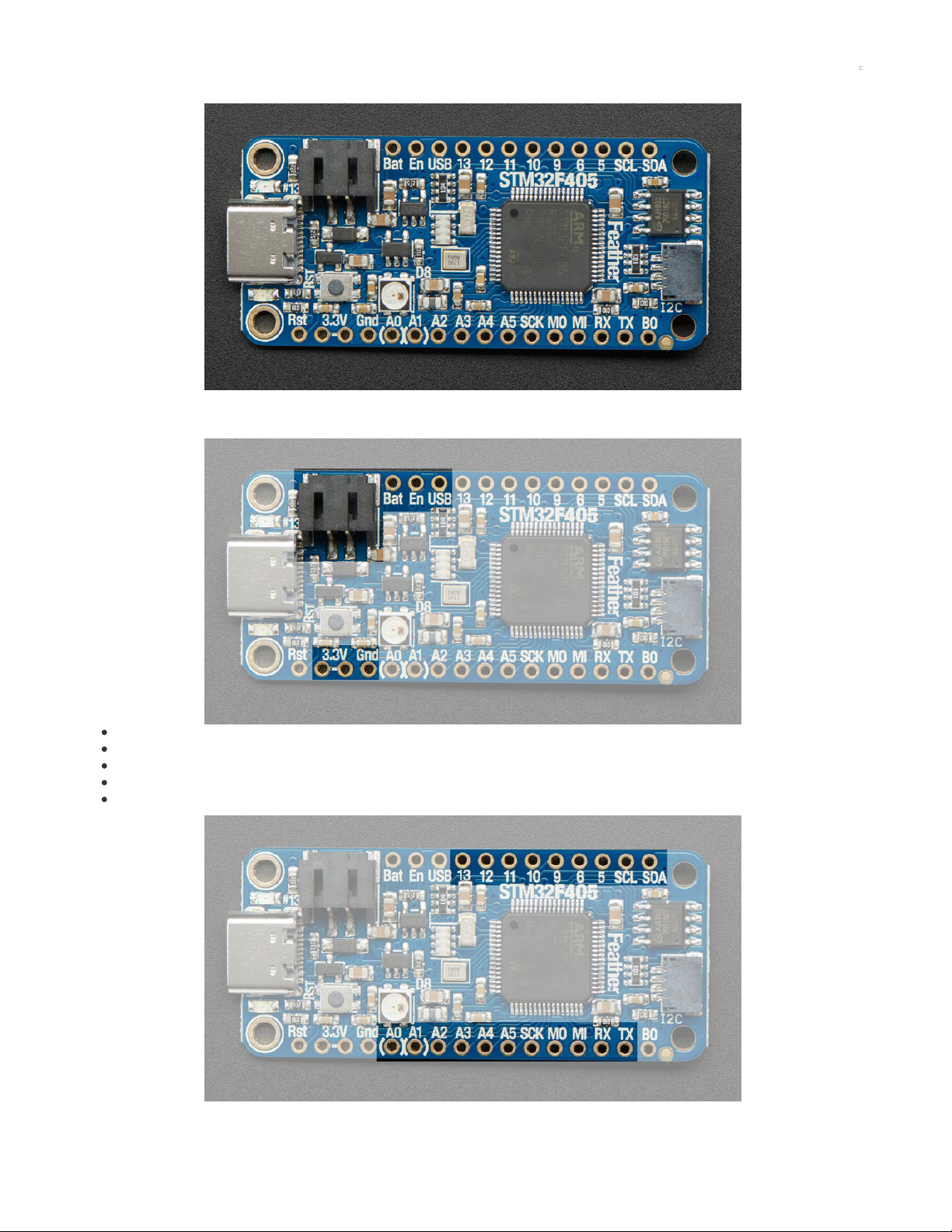
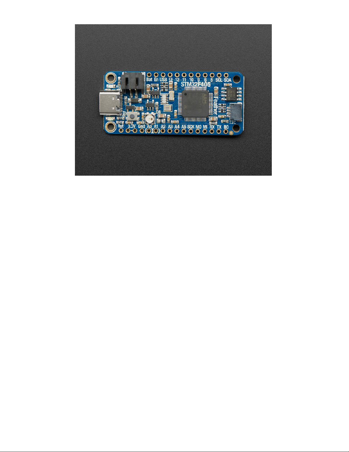
Pinouts
The Feather STM32F405 is chock-full of microcontroller goodness. There's also a lot of pins and ports. We'll take you a tour of them now!
Power Pins
GND - this is the common ground for all power and logic
BAT - this is the positive voltage to/from the JST jack for the optional Lipoly battery
USB - this is the positive voltage to/from the USB C jack if connected
EN - this is the 3.3V regulator's enable pin. It's pulled up, so connect to ground to disable the 3.3V regulator
3V - this is the output from the 3.3V regulator, it can supply 500mA peak
This is the general purpose I/O pin set for the microcontroller.
© Adafruit Industries https://learn.adafruit.com/adafruit-stm32f405-feather-express Page 6 of 31
Page 7

All logic is 3.3V, nearly all pins are 5V compliant
Many pins can do PWM output
All pins can be interrupt inputs
RX / GPIO 0 / PB11
Receive (input) pin for Serial3. Hardware USART3
PWM out on TIM2_CH4
Alternate uses: I2C2 SDA
TX / GPIO 1 / PB10
Transmit (output) pin for Serial3. Hardware USART3
PWM out on TIM2_CH3
Alternate uses: I2C2 SCL
SDA / GPIO 14 / PB7
The I2C (Wire) data pin, this has a 10K pullup to 3.3V. Hardware I2C1
PWM out on TIM4_CH2
Alternate uses: USART1 RX
SCL / GPIO 15 / PB6
the I2C (Wire) clock pin, this has a 10K pullup to 3.3V. Hardware I2C1
PWM out on TIM4_CH1
Alternate uses: USART1 TX, CAN2 TX
GPIO 5 / PC7
PWM out on TIM3_CH2
Alternate uses: USART6 RX, I2S3 MCK
GPIO 6 / PC6
PWM out on TIM3_CH1
Alternate uses: USART6 TX, I2S2 MCK
GPIO 9 / PB8
PWM out on TIM4_CH3
Alternate uses: CAN1 RX, I2C1 SCL
GPIO 10 / PB9
PWM out on TIM4_CH4
Alternate uses: CAN1 TX, I2C1 SDA
GPIO 11 / PC3
No PWM
Alternate uses: I2S2 SD, SPI2 MOSI
GPIO 12 / PC2
No PWM
Alternate uses: I2S2ext SD, SPI2 MISO
GPIO 13 / PC1
Connected to the red LED next to the USB jack
No PWM or alternate uses
SCK / GPIO23 / PB13
The SPI bus clock pin. Hardware SPI2
PWM out on TIM1_CH1N (available in Arduino, not CircuitPython)
Alternate uses: I2S2 Clock, CAN2 TX
MISO / GPIO24 / PB14
The SPI bus clock pin. Hardware SPI2
PWM out on TIM1_CH2N
Alternate uses: I2S2ext SD
MOSI / GPIO25 / PB15
The SPI bus clock pin. Hardware SPI2
PWM out on TIM1_CH3N
Alternate uses: I2S2 SD
Analog Pins:
A0 / GPIO 16 / PA4
This pin is analog
input
A0 (ADC12 IN4)
Analog
output
(DAC OUT1) due to having a DAC (digital-to-analog converter). You can set the raw voltage to anything from 0 to 3.3V, unlike
PWM outputs this is a true analog output
No PWM or alternate uses
A1 / GPIO 17 / PA5
This pin is analog
input
A1 (ADC12 IN5)
Analog
output
(DAC OUT2) due to having a DAC (digital-to-analog converter). This is the second DAC, and is 'independent' of A0. You can set
© Adafruit Industries https://learn.adafruit.com/adafruit-stm32f405-feather-express Page 7 of 31
Page 8

the raw voltage to anything from 0 to 3.3V, unlike PWM outputs this is a true analog output.
Alternative uses: SPI1 SCK
A2 / GPIO18 / PA6
This pin is analog
input
A2 (ADC12 IN6)
Alternative uses: SPI1 MISO
PWM out on TIM3_CH1
A3 / GPIO19 / PA7
This pin is analog
input
A3 (ADC12 IN7)
Alternative uses: SPI1 MOSI
PWM out on TIM3_CH2
A4 / GPIO20 / PC4
This pin is analog
input
A4 (ADC12 IN14)
A5 / GPIO21 / PC5
This pin is analog
input
A5 (ADC12 IN15)
A6 is also available for reading the battery voltage, see the Power Management page for instructions how
I2S Pins:
#1/Tx - I2S2 bit_clock pin.
#6 - I2S2 master clock pin
#10 - I2S2 word_select pin.
#11 - I2S2 data pin.
Note at this time we have not tested I2S in Arduino or MicroPython. There is no support yet in CircuitPython.
CAN Pins:
#9 - CAN1 RX
#10 - CAN1 TX
CircuitPython has CAN support via the canio module. MicroPython also supports CAN. Arduino has an open issue (https://adafru.it/GDf), no support.
SD Card / SDIO Pins
On the bottom of the PCB is a micro SD card slot. Unlike other Feathers, this is connected to the SDIO port ( PC8 thru PC12 plus PD2).
In Arduino, SDIO is well supported via the STM32SD library (https://adafru.it/GDg) .CircuitPython and MicroPython support SDIO. In CircuitPython
use the sdioio module.
The SD detect pin is on PB12 a.k.a D32.
BAT Pins
The bottom has a test point named BAT near the center of the board. You can use it to keep the STM32's real-time clock, backup registers, and
backup SRAM running while the rest of the chip is powered down.
DO NOT connect the BAT test point to the BAT pin at the side of the Feather. The voltage from a fully charged LiPo could damage the
STM32.
SWD Port
On the bottom there is also a 2x5 connector pad that can be used to connect an SWD debug port for advanced uses. We don't solder the
© Adafruit Industries https://learn.adafruit.com/adafruit-stm32f405-feather-express Page 8 of 31
Page 9
connector in place because it would take up space and make it hard to insert into a breadboard. However, you can pick up a 2x5
connector (https://adafru.it/HOf) and solder it yourself! Pinout matches any/all JLink/SWD programmers with 2x5 connectors.
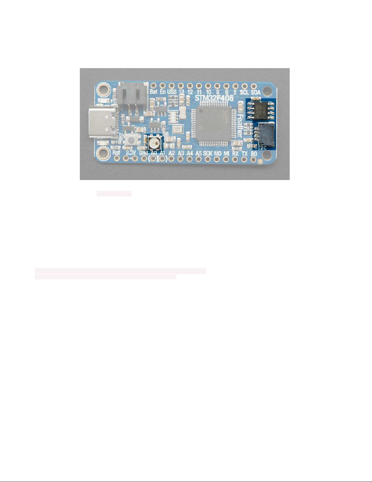
SPI Flash, STEMMA and NeoPixel
As part of the 'Express' series of boards, the Feather STM32F405 Express is designed for use with CircuitPython. To make that easy, we have
added two extra parts to this Feather: a mini NeoPixel (RGB LED) and a 2 MB SPI Flash chip.
The NeoPixel is connected to pin #8 in Arduino, so just use our NeoPixel library (https://adafru.it/dhw) and set it up as a single-LED strand on pin 8.
CircuitPython, the NeoPixel is board.NEOPIXEL and the library for it is here (https://adafru.it/wby) and in the bundle (https://adafru.it/uap). The
NeoPixel is powered by the 3.3V power supply but that hasn't shown to make a big difference in brightness or color. The NeoPixel is
not used by
the built in STM32 bootloader!
This is different than our M0/M4/nRF52840 boards
The SPI Flash is connected to SPI bus 1 pins that are not brought out on the GPIO pads. This way you don't have to worry about the SPI flash
colliding with other devices on the main SPI connection.
We give the SPI Flash the 'faster' SPI port 1 because there is no QSPI support, and reading fast from the SPI is important if you want to stream audio
clips or GIFs.
In CircuitPython the SPI flash is automatically used as the filesystem exposed over USB.
In Arduino you can access SPI flash with our library (https://adafru.it/wbt) and adding this definition to the top of your sketch to instantiate the SPI
flash.
SPIClass SPI_FLASH(PIN_SPI1_MOSI, PIN_SPI1_MISO, PIN_SPI1_SCK, PIN_SPI1_SS);
Adafruit_FlashTransport_SPI flashTransport(PIN_SPI1_SS, &SPI_FLASH);
Note that our SPI flash library cannot be used at the same time as the SDIO library because they have colliding File definitions.
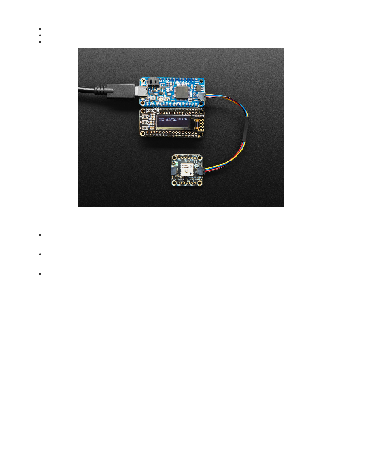
The Qwiic / STEMMA QT port is a JST SH 1.0mm pitch connector that gives a plug-and-play connection to 3.3V, GND, SDA and SCL. Perfect for
attaching a wide variety of sensors. Check out our wide range of cables and devices that can be chained together just like this mini GPS
module: (https://adafru.it/GfR)
© Adafruit Industries https://learn.adafruit.com/adafruit-stm32f405-feather-express Page 9 of 31
Page 10

© Adafruit Industries https://learn.adafruit.com/adafruit-stm32f405-feather-express Page 10 of 31
Page 11
Assembly
We ship Feathers fully tested but without headers attached - this gives you the most flexibility on choosing how to use and configure your Feather
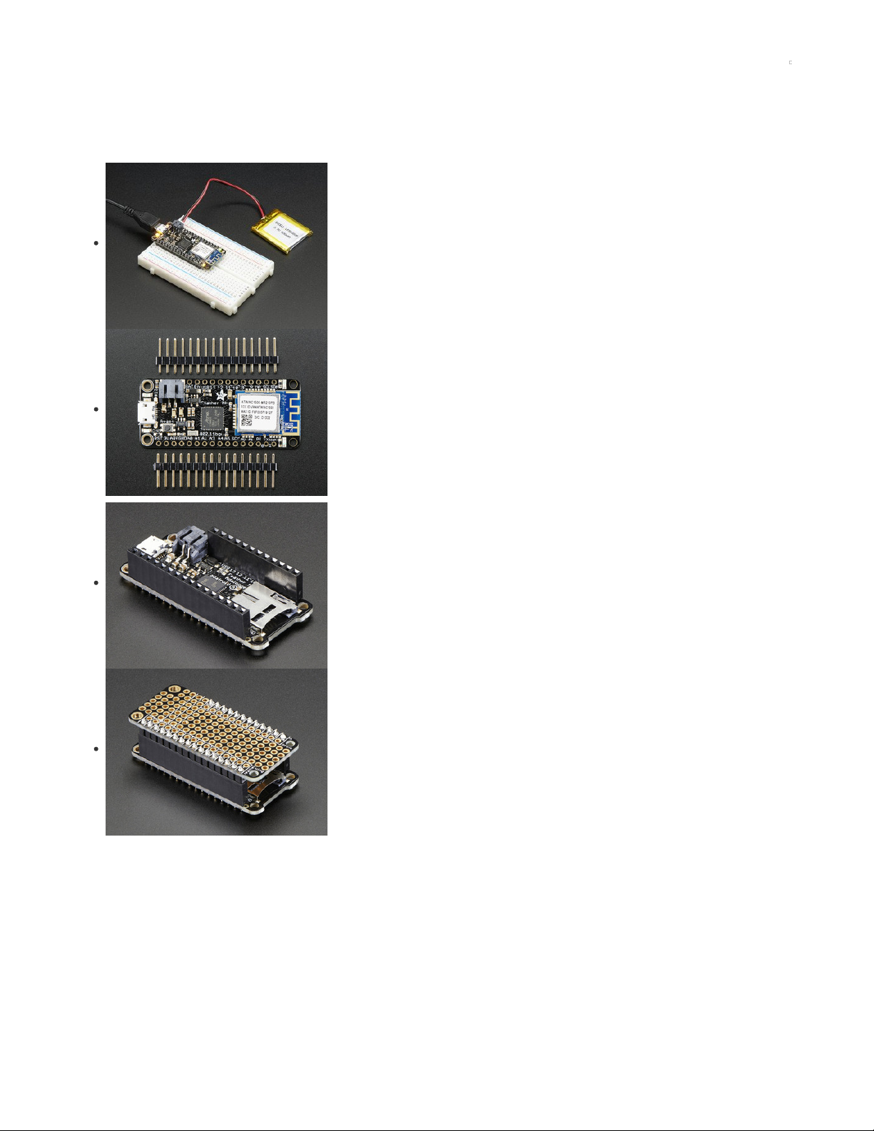
Header Options!
Before you go gung-ho on soldering, there's a few options to consider!
The first option is soldering in plain male headers, this lets you plug in the Feather into a solderless
breadboard
Another option is to go with socket female headers. This won't let you plug the Feather into a breadboard
but it will let you attach featherwings very easily
© Adafruit Industries https://learn.adafruit.com/adafruit-stm32f405-feather-express Page 11 of 31
Page 12

We also have 'slim' versions of the female headers, that are a little shorter and give a more compact shape
Finally, there's the "Stacking Header" option. This one is sort of the best-of-both-worlds. You get the ability
to plug into a solderless breadboard
and
plug a featherwing on top. But its a little bulky
Soldering in Plain Headers
Prepare the header strip:
Cut the strip to length if necessary. It will be easier to solder if you insert it into a breadboard - long pins
down
© Adafruit Industries https://learn.adafruit.com/adafruit-stm32f405-feather-express Page 12 of 31
Page 13

Add the breakout board:
Place the breakout board over the pins so that the short pins poke through the breakout pads
And Solder!
Be sure to solder all pins for reliable electrical contact.
(For tips on soldering, be sure to check out our Guide to Excellent Soldering
(https://adafru.it/aTk)
).
© Adafruit Industries https://learn.adafruit.com/adafruit-stm32f405-feather-express Page 13 of 31
Page 14

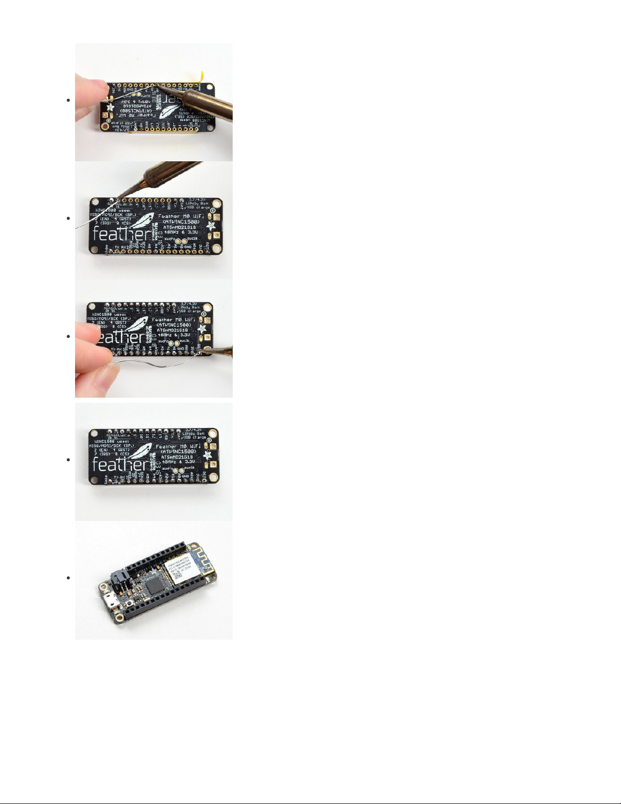
Solder the other strip as well.
You're done! Check your solder joints visually and continue onto the next steps
Soldering on Female Header
Tape In Place
For sockets you'll want to tape them in place so when you flip over the board they don't fall out
© Adafruit Industries https://learn.adafruit.com/adafruit-stm32f405-feather-express Page 14 of 31
Page 15
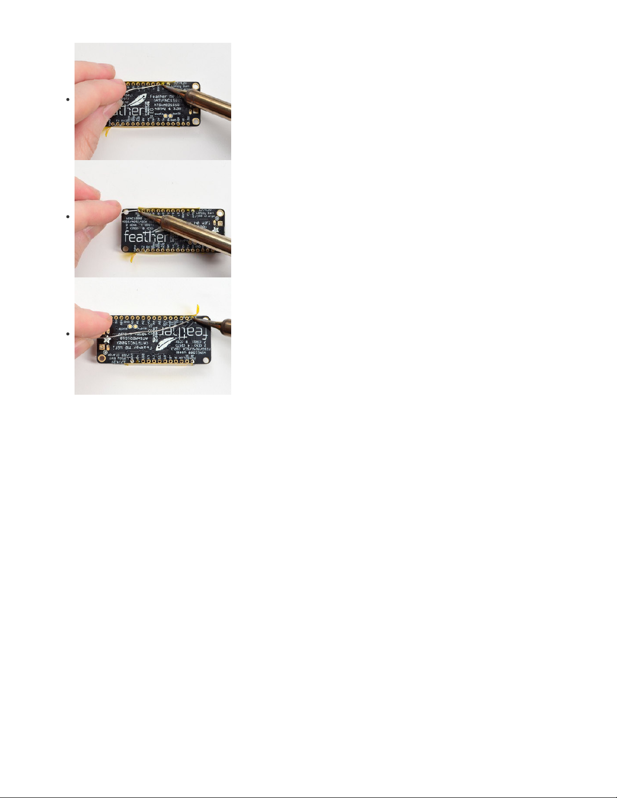
Flip & Tack Solder
After flipping over, solder one or two points on each strip, to 'tack' the header in place
© Adafruit Industries https://learn.adafruit.com/adafruit-stm32f405-feather-express Page 15 of 31
Page 16
And Solder!
Be sure to solder all pins for reliable electrical contact.
(For tips on soldering, be sure to check out our Guide to Excellent
Soldering
(https://adafru.it/aTk)
).
You're done! Check your solder joints visually and continue onto the next steps
© Adafruit Industries https://learn.adafruit.com/adafruit-stm32f405-feather-express Page 16 of 31
Page 17
Power Management
Battery + USB Power
We wanted to make the Feather easy to power both when connected to a computer as well as via battery. There's two ways to power a Feather.
You can connect with a USB C cable (just plug into the jack) and the Feather will regulate the 5V USB down to 3.3V. You can also connect a
4.2/3.7V Lithium Polymer (Lipo/Lipoly) or Lithium Ion (LiIon) battery to the JST jack. This will let the Feather run on a rechargable battery. When the
USB power is powered, it will automatically switch over to USB for power, as well as start charging the battery (if attached) at 100mA. This
happens 'hotswap' style so you can always keep the Lipoly connected as a 'backup' power that will only get used when USB power is lost.
The JST connector polarity is matched to Adafruit LiPoly batteries. Some 3rd party batteries ship with the opposite polarity, and using them
can destroy your Feather! Always double check your wires before choosing a battery to use with your project.
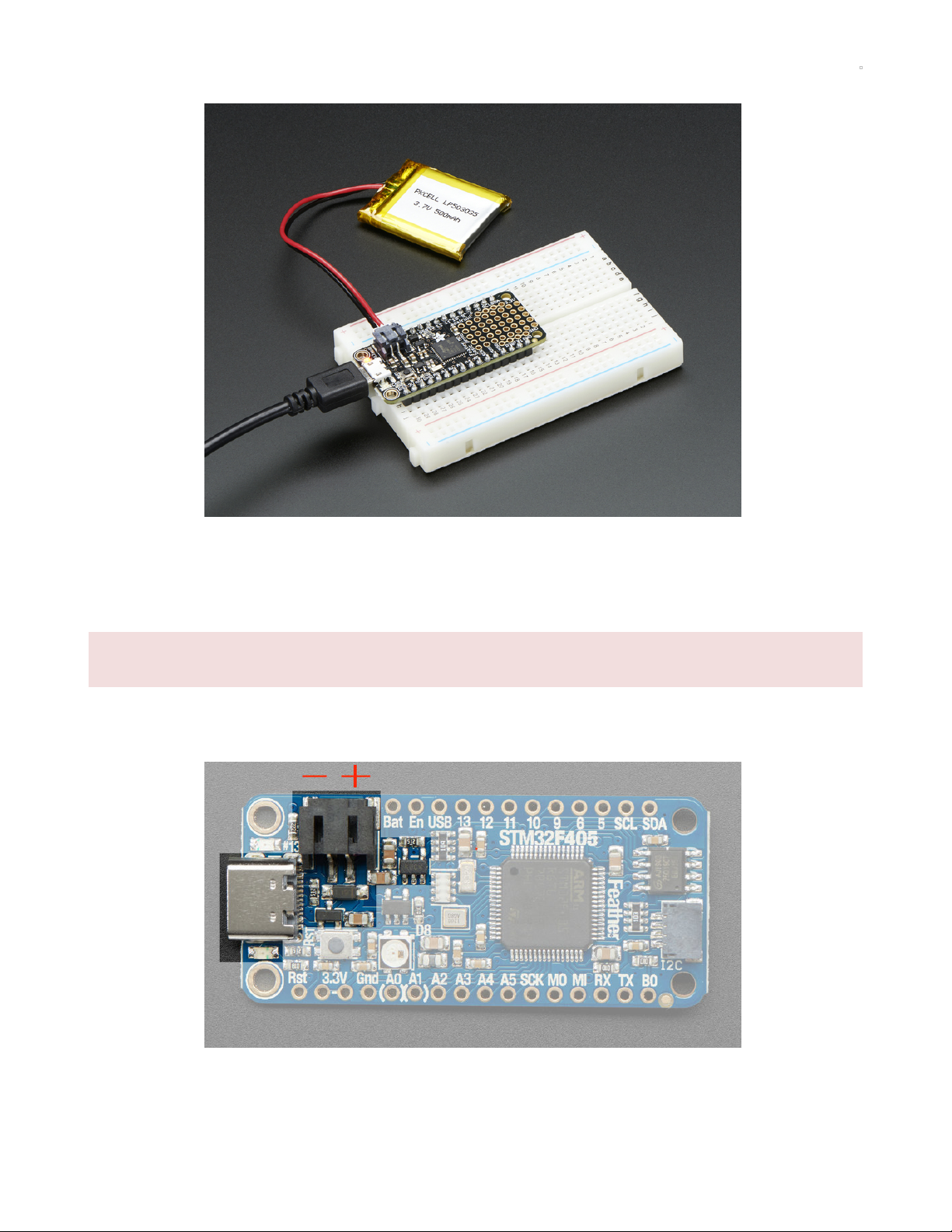
The below image shows the USB C jack (left), Lipoly JST jack (above and to the right of the USB), as well as the changeover diode (just below JST
jack) and the Lipoly charging circuitry (to the right of the JST jack). There's also a CHG LED, which will light up while the battery is charging. This
LED might also flicker if the battery is not connected.
Power supplies
You have a lot of power supply options here! We bring out the BAT pin, which is tied to the lipoly JST connector, as well as USB which is the +5V
from USB if connected. We also have the 3V pin which has the output from the 3.3V regulator. We use a 500mA peak regulator. While you can get
© Adafruit Industries https://learn.adafruit.com/adafruit-stm32f405-feather-express Page 17 of 31
Page 18
500mA from it, you can't do it continuously from 5V as it will overheat the regulator. It's fine for, say, powering an ESP8266 WiFi chip or XBee radio
though, since the current draw is 'spikey' & sporadic.
Note the STM32F405 is a fairly power hungry chip, it will draw up to 80mA when it runs
Measuring Battery
If you're running off of a battery, chances are you wanna know what the voltage is at! That way you can tell when the battery needs recharging.
Lipoly batteries are 'maxed out' at 4.2V and stick around 3.7V for much of the battery life, then slowly sink down to 3.2V or so before the protection
circuitry cuts it off. By measuring the voltage you can quickly tell when you're heading below 3.7V
To make this easy we stuck a double-100K resistor divider on the BAT pin, and connected it to A6 which is not exposed on the feather breakout
In Arduino, you can read this pin's voltage, then double it, to get the battery voltage.
// Arduino Example Code snipp et
#define VBATPIN A6
float measuredvbat = analogRe ad(VBATPIN);
measuredvbat *= 2; // we d ivided by 2, so multiply bac k
measuredvbat *= 3.3; // Mult iply by 3.3V, our reference voltage
measuredvbat /= 1024; // conv ert to voltage
Serial.print("VBat: " ); Seri al.println(measuredvbat);
For CircuitPython, we've written a get_voltage() helper function to do the math for you. All you have to do is call the function, provide the pin and
print the results.
import board
from analogio import AnalogIn
vbat_voltage = AnalogIn(board .VOLTAGE_MONITOR)
def get_voltage(pin):
return (pin.value * 3.3) / 65536 * 2
battery_voltage = get_voltage (vbat_voltage)
print("VBat voltage: {:.2f}". format(battery_voltage))
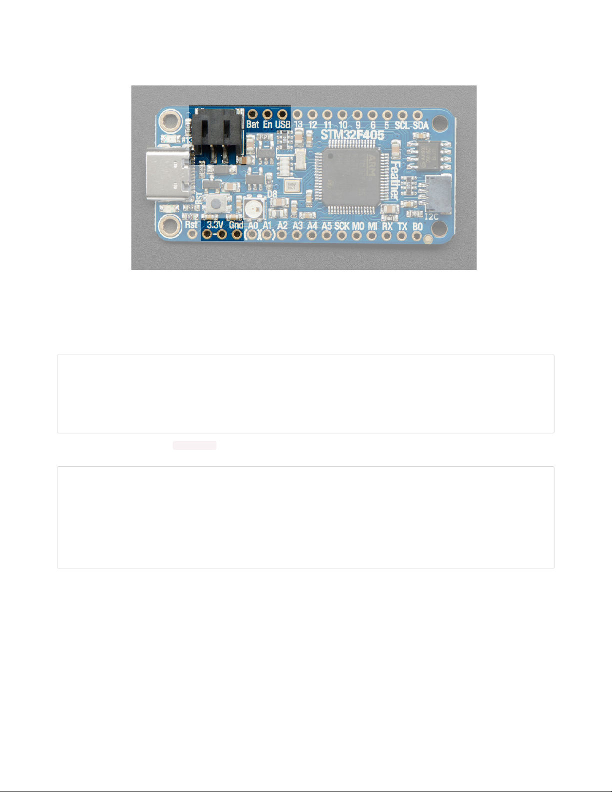
ENable pin
If you'd like to turn off the 3.3V regulator, you can do that with the EN(able) pin. Simply tie this pin to Ground and it will disable the 3V regulator.
The BAT and USB pins will still be powered
© Adafruit Industries https://learn.adafruit.com/adafruit-stm32f405-feather-express Page 18 of 31
Page 19

Alternative Power Options
The two primary ways for powering a feather are a 3.7/4.2V LiPo battery plugged into the JST port or a USB power cable.
If you need other ways to power the Feather, here's what we recommend:
For permanent installations, a 5V 1A USB wall adapter (https://adafru.it/duP) will let you plug in a USB cable for reliable power
For mobile use, where you don't want a LiPoly, use a USB battery pack! (https://adafru.it/e2q)
If you have a higher voltage power supply, use a 5V buck converter (https://adafru.it/DHs) and wire it to a USB cable's 5V and GND
input (https://adafru.it/DHu)
Here's what you cannot do:
Do not use alkaline or NiMH batteries and connect to the battery port - this will destroy the LiPoly charger and there's no way to disable the
charger
Do not use 7.4V RC batteries on the battery port - this will destroy the board
The Feather
is not designed for external power supplies
- this is a design decision to make the board compact and low cost. It is not recommended,
but technically possible:
Connect an external 3.3V power supply to the 3V and GND pins. Not recommended, this may cause unexpected behavior and the EN pin
will no longer enable/work. Also this doesn't provide power on BAT or USB and some Feathers/Wings use those pins for high current usages.
You may end up damaging your Feather.
Connect an external 5V power supply to the USB and GND pins. Not recommended, this may cause unexpected behavior when plugging in
the USB port because you will be back-powering the USB port, which
could
confuse or damage your computer.
© Adafruit Industries https://learn.adafruit.com/adafruit-stm32f405-feather-express Page 19 of 31
Page 20
DFU Bootloader Details
The STM32F405 chip has a built in ROM bootloader that cannot be disabled or erased, this makes it a fool-proof way to always be able to recover
your microcontroller code. It's not as easy to use as UF2, but it isnt
too difficult
either.
The ROM bootloader looks for signal on the serial RX line as well as USB, so make sure no GPS or other serial/uart data device is connected to RX
while you are trying to bootload the device!
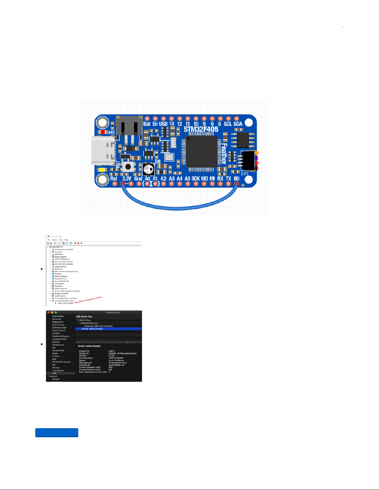
Enabling DFU bootloader mode
Enabling the DFU bootloader is super easy. Simply connect the BOOT0 (B0) pin to 3.3V logic. Then press the reset button or power cycle while the
board is connected to your computer USB port
After you've hit reset, you can remove the BOOT0 jumper - it's only checked on powerup
Check for USB Bootloader device
In Windows, you will see the device show up as STM32 BOOTLOADER under Universal Serial Bus
devices
In MacOS X
Visit the AppleMenu->About This Mac->System Report
Select USB and look for the item labeled STM32 BOOTLOADER
Programming Firmware
Windows
The easiest way by far to program under windows is to download STM32CubeProg. It's a graphical programmer, does not require Zadig or special
command line invocation
You'll need to make an ST.com account is the only downside.
https://adafru.it/GDQ
https://adafru.it/GDQ
© Adafruit Industries https://learn.adafruit.com/adafruit-stm32f405-feather-express Page 20 of 31
Page 21
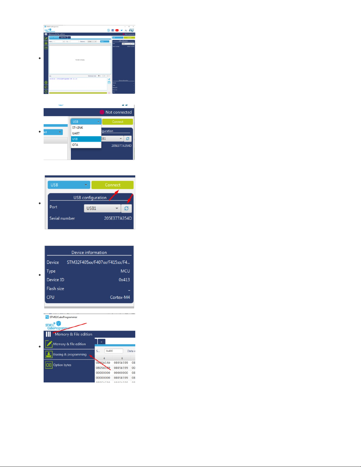
When you start it up, it'll look like this.
In the top right, below the Not Connected message, find the dropdown to the left of the Connect button
Select USB
OK if the device is plugged in and the bootloader is running, it will show up under the USB configuration
pane. If not, enter bootloader mode by connecting BOOT0 to 3.3V and resetting, and click the refresh
button.
Once it appears as a valid Port, click Connect
You should see the Device info pane in the bottom right is updated with info about what chip was found!
Click the 3-lines below the STM32 logo in the top left, to expand the menu.
Then click Erasing & Programming
© Adafruit Industries https://learn.adafruit.com/adafruit-stm32f405-feather-express Page 21 of 31
Page 22

Click Browse to open the firmware files you want to program
You can program .hex or .bin files, it does not seem to support .dfu
Don't change the Start Address
Make sure Verify Programming and Run after Programmingare clicked, but Skip flash erase is
not
Then click Start Programming
It will take a few seconds to erase and reprogram the chip.
It's normal to get a Warning Connection is lost alert
Click away until you get the File download complete alert
That's it! You should close STM32 CubeProg now - leaving the program open may conflict with other
connections to the board.
Mac (and Linux)
For Mac users, install dfu-util with brew
dfu-util can only program .bin and .dfu files. It cannot program .hex files (but there are tools to convert .hex's to .bin's)
Then upload the firmware with the command
dfu-util -a 0 --dfuse-address 0x08000000 -D firmware.bin
Don't change the address value, only the firmware filename!
© Adafruit Industries https://learn.adafruit.com/adafruit-stm32f405-feather-express Page 22 of 31
Page 23

Or, if you have a dfu file - use
dfu-util -a 0 -D firmware.dfu
© Adafruit Industries https://learn.adafruit.com/adafruit-stm32f405-feather-express Page 23 of 31
Page 24

Arduino IDE Setup
The first thing you will need to do is to download the latest release of the Arduino IDE. You will need to be using version 1.8 or higher for this guide
https://adafru.it/f1P
Thankfully the Adafruit board support is now supported directly from STM32duino so you can simply install it:
From the File menu select Preferences
Find the Additional Board Manager URLs text box.
If it's empty add the text
https://github.com/stm32duino/BoardManagerFiles/raw/master/STM32/package_stm_index.json (https://adafru.it/HOA)
or, if its not empty, add a comma at the end of the current text, and then add the line above
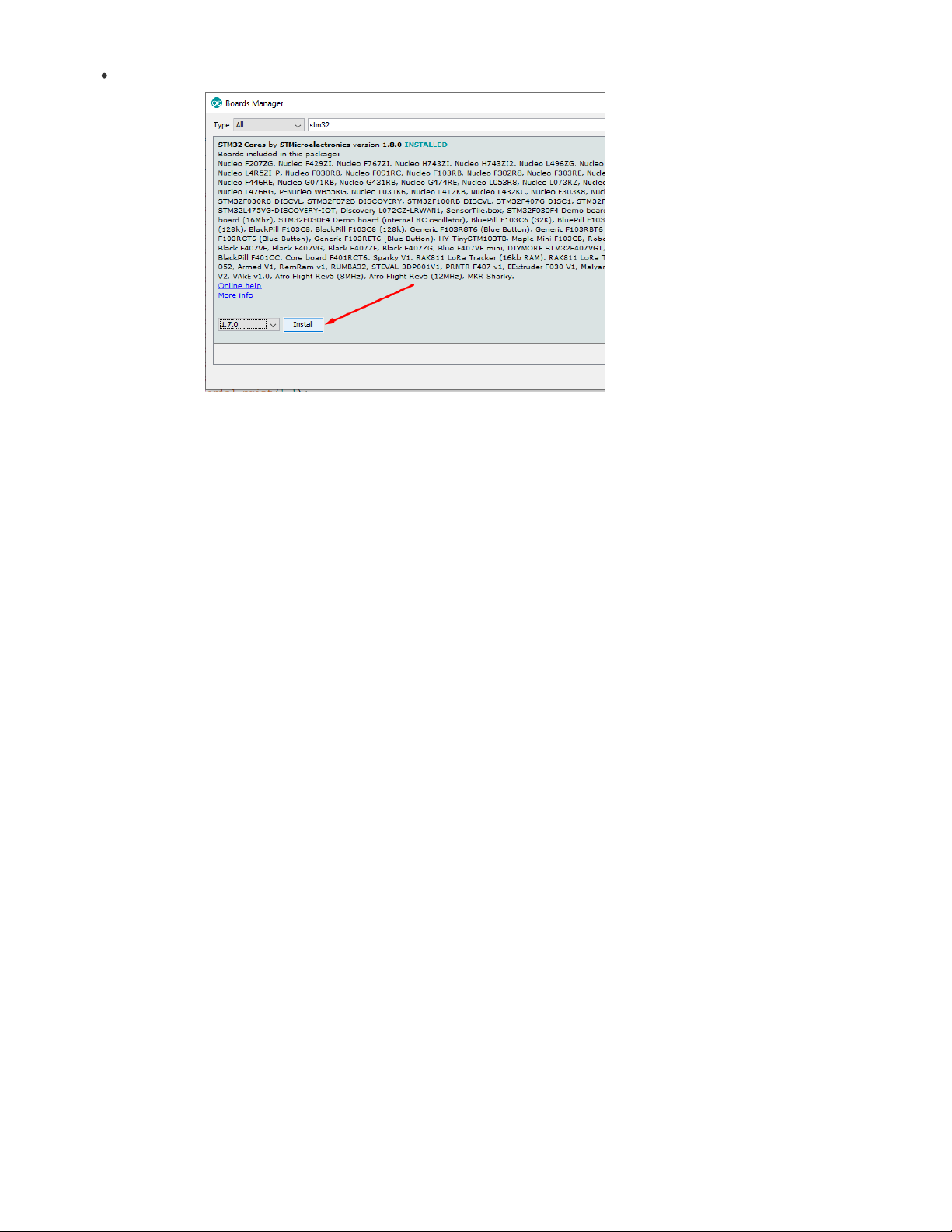
From the Tools menu, go down to Board submenu and select Board Manager...
Search for STM32 and click Install - make sure you have the latest version,
at least 1.8.0
selected and
installed!
Quit and restart the Arduino IDE
https://adafru.it/f1P
© Adafruit Industries https://learn.adafruit.com/adafruit-stm32f405-feather-express Page 24 of 31
Page 25

From the Tools menu, select Generic STM32F4
Then select Board part number -> Adafruit Feather STM32F405
Under USB Support select CDC supercedes USART so that Serial points to the USB port not the hardware
serial
Finally select STM32CubeProgrammer (DFU) as the upload method
These are your Tool menu selections to verify!
© Adafruit Industries https://learn.adafruit.com/adafruit-stm32f405-feather-express Page 25 of 31
Page 26

Note that if you tried the STM32 Cube Programmer on the "DFU Bootloader Details" page, you need to close it before using this Arduino
version! Our users report the application and the Arduino upload method can conflict with each other, so make sure you are only using one at a
time or you may find your uploads failing to connect.
Activate the Bootloader
At this time, you must manually put the board into bootloader mode every time you want to upload.
Do that by connecting the B0 pin to 3.3V and clicking
reset
STM32CubeProgrammer will run the code immediately after DFU, so you can connect a wire on a breadboard between B0 and 3.3V and
keep it connected. When you are about to upload, click the reset button. After upload, your code will be running automatically.
There's work in progress to have STM32 auto-reload, hopefully that will make it into a release soon! (https://adafru.it/GD9)
Upload!
Once you are bootloader mode, click Upload to compile and upload your sketch
STM32duino Notes
Hardware Serial UART is on Serial3 not Serial1 as is usually called
Yes NeoPixel library has support for STM32F4!
© Adafruit Industries https://learn.adafruit.com/adafruit-stm32f405-feather-express Page 26 of 31
Page 27
The SDIO SD card is supported by this library (https://adafru.it/GDg)
© Adafruit Industries https://learn.adafruit.com/adafruit-stm32f405-feather-express Page 27 of 31
Page 28

MicroPython Setup
We don't really support MicroPython explictly at Adafruit - our drivers are for CircuitPython. However, for people who like MicroPython, we
submitted a build definition (https://adafru.it/GDT)!
You can build the latest version from the github or load this MicroPython 1.9.4 build we crafted for you.
Load it by following the DFU Bootloader (https://adafru.it/HOB) tutorial in this guide. Follow the instructions for when you have a .dfu file.
https://adafru.it/GDU
Upon success, reset the board without the BOOT0 jumper and you will see after a few seconds the PYBFLASH disk drive appear
That's it! You can now follow along MicroPython documentation and tutorials to learn more about how to use MicroPython (https://adafru.it/GDV).
MicroPython Notes
The Feather uses the same chip as the PyBoard 1.1 so technically anything available on the PyBoard should work on the Feather, given the pin
differences
We use Dx and Ax pin names, to match the Feather markings. You can see the pin names here (https://adafru.it/GDW)
The SD card slot can be used for file and code storage (https://adafru.it/GDX)
SPI flash is not used by MicroPython (it's something specific to CircuitPython)
https://adafru.it/GDU
© Adafruit Industries https://learn.adafruit.com/adafruit-stm32f405-feather-express Page 28 of 31
Page 29
CircuitPython Setup
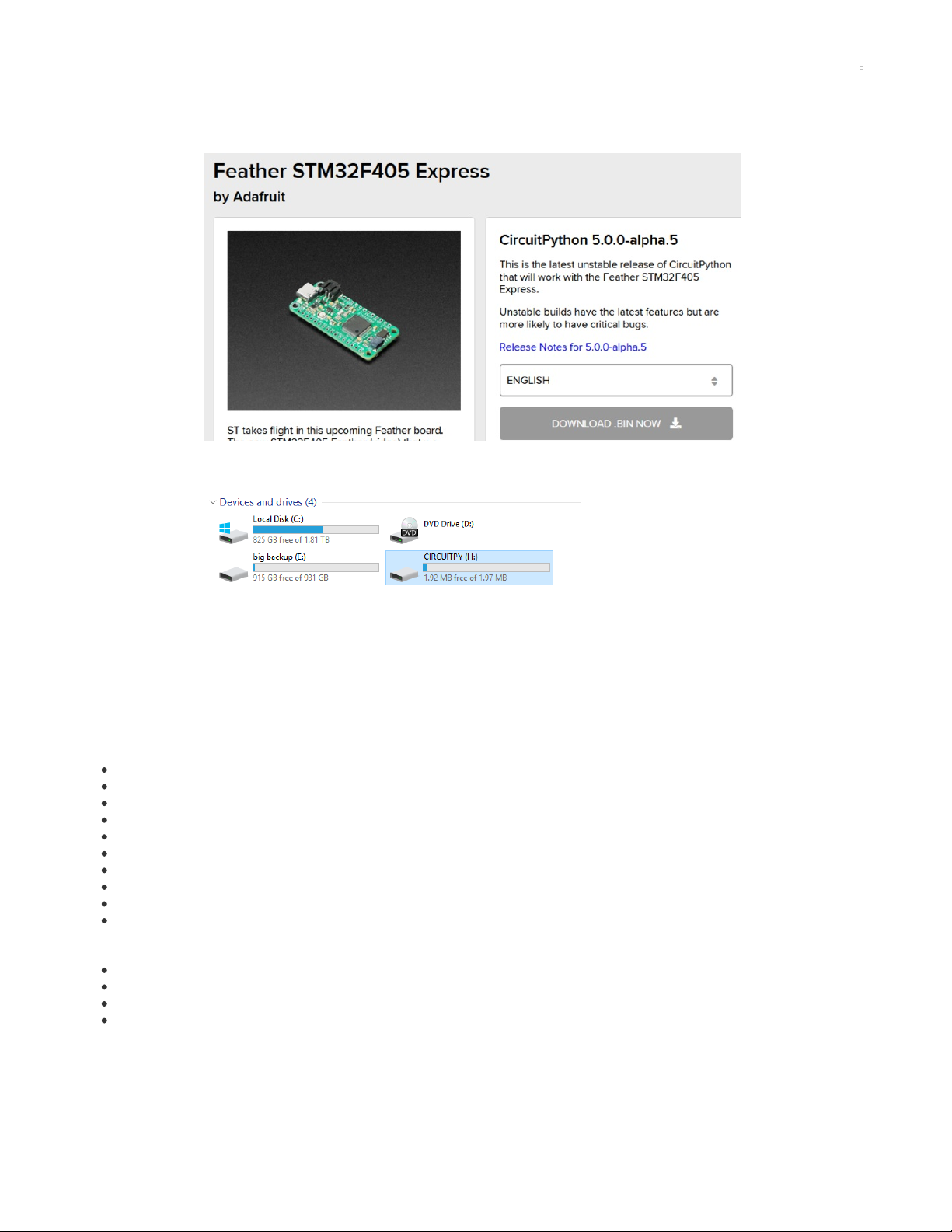
To load CircuitPython, follow the DFU Bootloader instructions to get the board into bootloader mode
Visit https://circuitpython.org/board/feather_stm32f405_express/ (https://adafru.it/GDY) To get the latest firmware available
Download the bin file, and then program it using dfu-util or STM32CubeProgrammer (https://adafru.it/HOB)
Upon success, reset the board without the BOOT0 jumper and you will see after a few seconds the CIRCUITPY disk drive appear
Next you can visit https://learn.adafruit.com/welcome-to-circuitpython (https://adafru.it/cpy-welcome)and https://learn.adafruit.com/circuitpython-
essentials/ (https://adafru.it/BX8) to learn more about CircuitPython
CircuitPython Notes
If you are intending to start a project that is very RAM intensive, note you cannot access the full 196KB of RAM that listed on the F405 datasheet
and website - only 128KB is available to Circuitpython programs for system reasons. You'll find the same limitation on Micropython and most other
F405 devices.
STM32F4 support is new compared to the SAMD and nRF boards, but is now considered stable. Working modules on this board include:
Digital IO (LEDs/buttons)
analog input
analog output (DAC)
PWM output on timer pins
I2C
SPI
NeoPixel Support (https://adafru.it/GDZ)
UART Support (https://adafru.it/GD-)
DisplayIO
PulseIO
To come:
I2S
Audio
TouchIO
many others!
If you find something missing or flawed, please open an issue in circuitpython (https://adafru.it/GE0)
© Adafruit Industries https://learn.adafruit.com/adafruit-stm32f405-feather-express Page 29 of 31
Page 30

Downloads
Files
ST STM32F405 Product Page (https://adafru.it/GE1) - datasheets and app notes are found here
Fritzing object in Adafruit Fritzing Library (https://adafru.it/aP3)
EagleCAD PCB files on GitHub (https://adafru.it/IfP)
Schematic & Fabrication Print
© Adafruit Industries https://learn.adafruit.com/adafruit-stm32f405-feather-express Page 30 of 31
Page 31

© Adafruit Industries Last Updated: 2021-03-26 10:58:29 AM EDT Page 31 of 31
 Loading...