

Page 1
Adafruit AirLift Shield - ESP32 WiFi Co-Processor
Created by Brent Rubell
Last updated on 2021-03-29 01:04:51 PM EDT
Page 2

2
4
8
8
9
9
10
10
11
12
12
16
21
21
21
22
24
24
24
28
30
31
32
33
36
36
36
36
36
37
37
38
41
41
41
42
43
44
46
47
48
48
49
50
52
53
Guide Contents
Guide Contents
Overview
Pinouts
Power Pins
SPI Interface Pins
ESP32 Control Pins
SD Card Interface
LEDs
Prototyping Area
Assembly
Installing Standard Headers
Stack Alert!
CircuitPython WiFi
CircuitPython Microcontroller Pinout
CircuitPython Installation of ESP32SPI Library
CircuitPython Usage
Internet Connect!
What's a secrets file?
Connect to WiFi
Requests
HTTP GET with Requests
HTTP POST with Requests
Advanced Requests Usage
WiFi Manager
CircuitPython BLE
CircuitPython BLE UART Example
Adafruit AirLift ESP32 Shield Wiring
Update the AirLift Firmware
Install CircuitPython Libraries
Install the Adafruit Bluefruit LE Connect App
Copy and Adjust the Example Program
Talk to the AirLift via the Bluefruit LE Connect App
Arduino WiFi
Library Install
First Test
Arduino Microcontroller Pin Definition
WiFi Connection Test
Secure Connection Example
JSON Parsing Example
Adapting Other Examples
Upgrade External ESP32 Airlift Firmware
External AirLift FeatherWing, Shield, or ItsyWing
Upload Serial Passthrough code for Feather or ItsyBitsy
External AirLift Breakout
Code Usage
Install esptool.py
© Adafruit Industries https://learn.adafruit.com/adafruit-airlift-shield-esp32-wifi-co-processor Page 2 of 56
Page 3

53
54
54
54
55
55
55
55
Burning nina-fw with esptool
Verifying the Upgraded Firmware Version
Arduino
CircuitPython
Downloads
Files
Schematic
Fab Print
© Adafruit Industries https://learn.adafruit.com/adafruit-airlift-shield-esp32-wifi-co-processor Page 3 of 56
Page 4
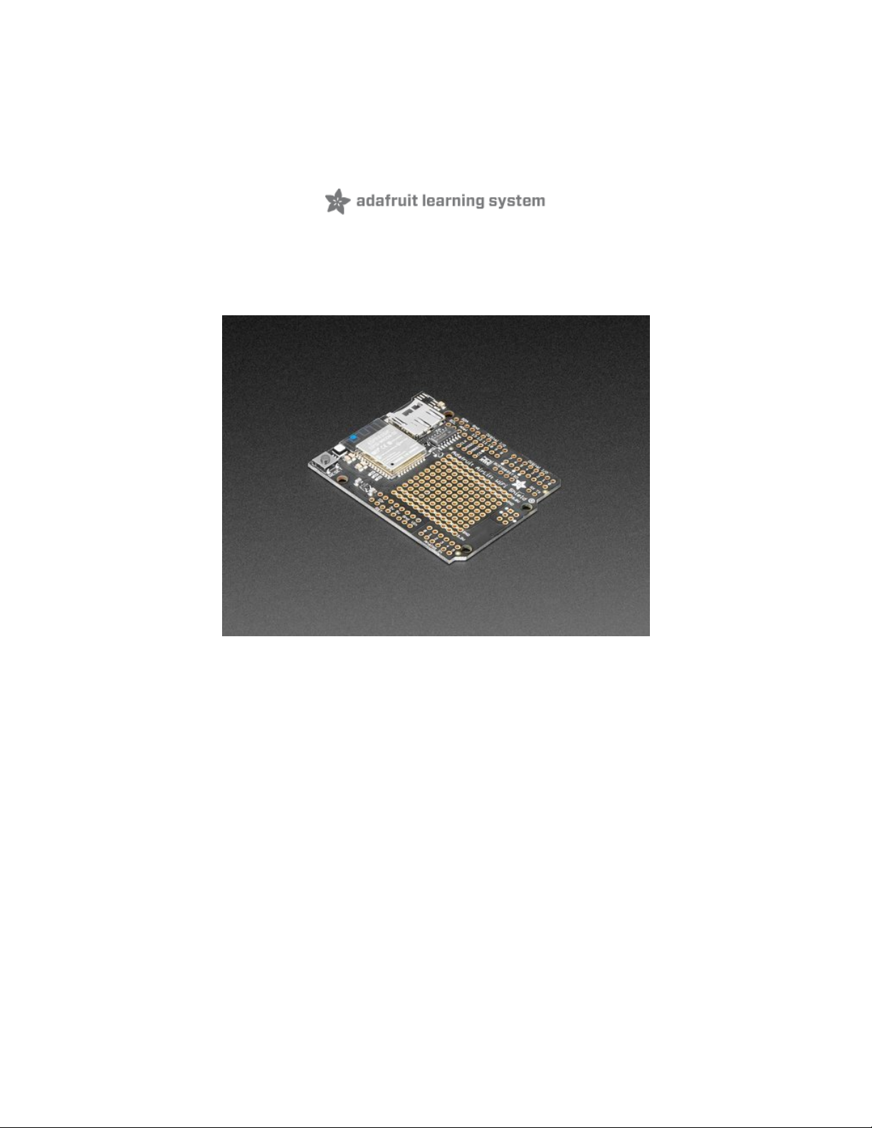
Overview
Give your Arduino project a
lift
with the Adafruit AirLift Shield (https://adafru.it/F6v) - a shield that lets you
use the powerful ESP32 as a WiFi or BLE co-processor. You probably have your favorite Arduino-
compatible (like the Metro M4 (https://adafru.it/A5S) or the classic Metro
328 (https://adafru.it/METROXMETR)) that comes with its own set of awesome peripherals and lots of
libraries. But it doesn't have WiFi or BLE built in! So let's give that chip a best friend, the ESP32. This chip
can handle all the heavy lifting of connecting to a WiFi network and transferring data from a site, even if it's
using the latest TLS/SSL encryption (it has root certificates pre-burned in).
© Adafruit Industries https://learn.adafruit.com/adafruit-airlift-shield-esp32-wifi-co-processor Page 4 of 56
Page 5
Having WiFi managed by a separate chip means your code is simpler, you don't have to cache socket
data, or compile in & debug an SSL library. Send basic but powerful socket-based commands over 8MHz
SPI for high speed data transfer. You can use any 3V or 5V Arduino, any chip from the ATmega328 and up
(although the '328 will not be able to do very complex tasks or buffer a lot of data). It also works great with
CircuitPython, a SAMD51/Cortex M4 minimum required since we need a bunch of RAM. All you need is the
SPI bus and 2 control pins plus a power supply that can provide up to 250mA during WiFi usage.
The ESP32 also supports BLE (Bluetooth Low Energy), though not simultaneously with WiFi. Many of our
CircuitPython builds include native support for ESP32 BLE. You use a few control pins and the RXI and
TXO pins to talk to the ESP32 when it's in BLE mode.
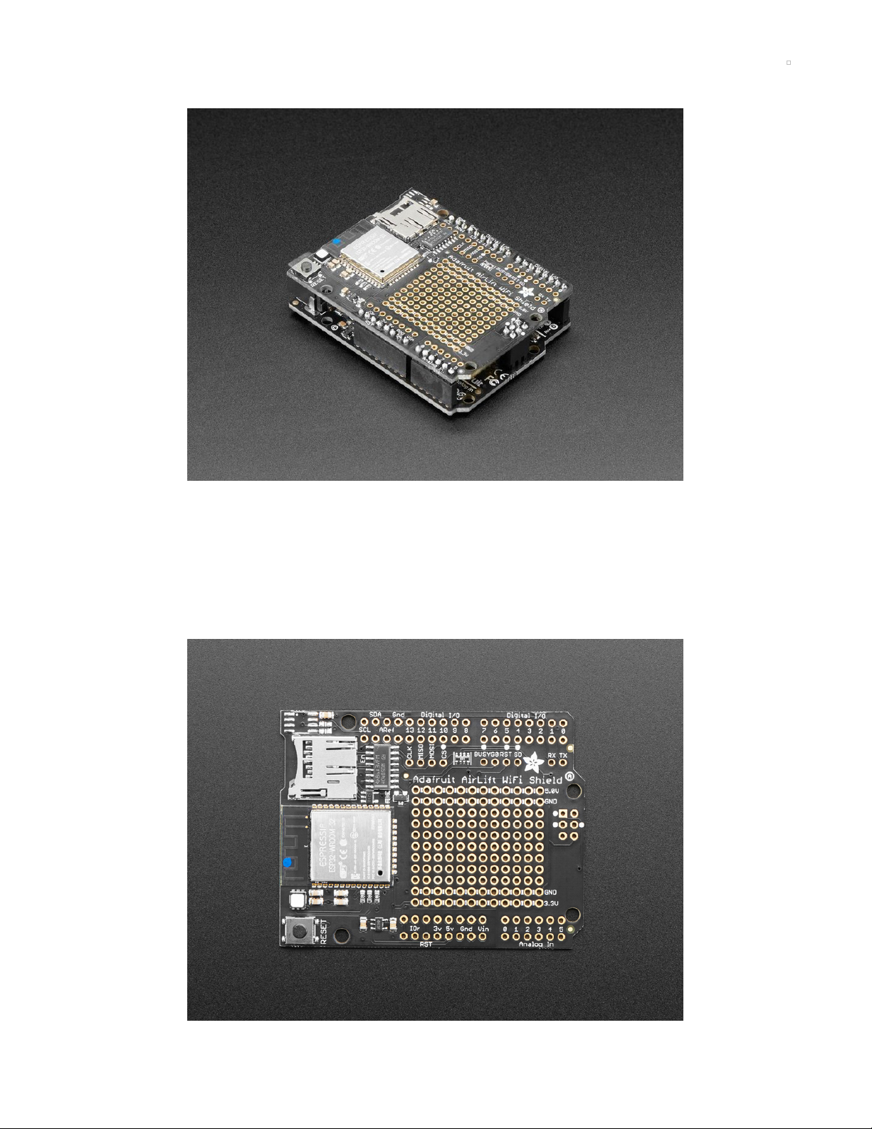
We placed an ESP32 module on a shield with a separate 3.3V regulator, and a tri-state chip for MOSI so
you can share the SPI bus with other shields. We also tossed on a micro SD card socket, you can use that
to host or store data you get from the Internet. Arduinos based on the ATmega328 (like the UNO) cannot
use both the WiFi module and SD library at the same time, they don't have enough RAM. Again, we
recommend an M0 or M4 chipset for use with Arduino, M4 for CircuitPython!
© Adafruit Industries https://learn.adafruit.com/adafruit-airlift-shield-esp32-wifi-co-processor Page 5 of 56
Page 6
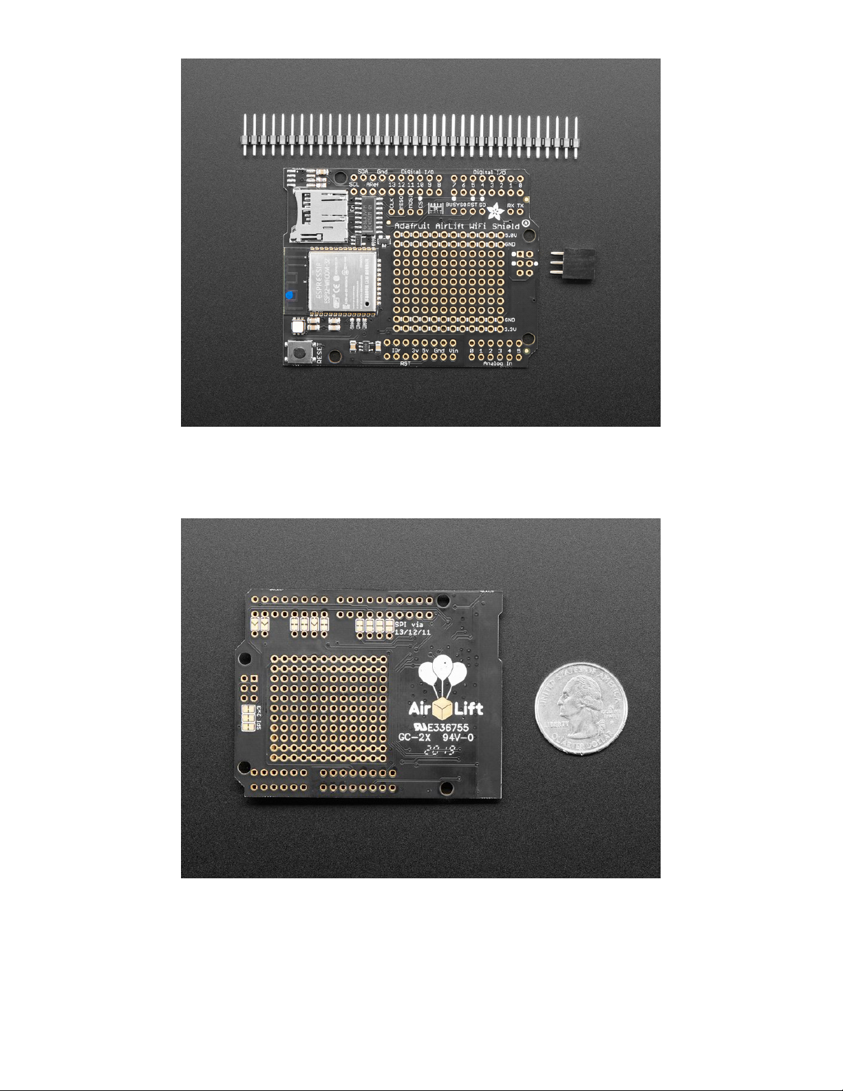
Comes fully assembled and tested, pre-programmed with ESP32 SPI WiFi co-processor firmware that you
can use in CircuitPython to use this into WiFi co-processsor (https://adafru.it/Evl). We also include some
header so you can solder it in and plug right into your Arduino-compatible, but you can also pick up a set
of stacking headers to stack above/below your board.
We've tested this with all our Metros and it should work just fine with them except the Metro M4
Airlifts (https://adafru.it/F6o) (because they already have WiFi!). For use in Arduino , the '328 and '32u4 you
can do basic connectivity and data transfer but they do not have a lot of RAM so we don't recommend
them - use the Metro M0, M4 or similar, for best results! For CircuitPython use, a Metro M4 works best -
the M0 series does not have enough RAM in CircuitPython.
© Adafruit Industries https://learn.adafruit.com/adafruit-airlift-shield-esp32-wifi-co-processor Page 6 of 56
Page 7

The firmware on board is a slight variant of the Arduino WiFiNINA core, which works
great! (https://adafru.it/E7O) At this time connection to Enterprise WiFi is not yet supported.
© Adafruit Industries https://learn.adafruit.com/adafruit-airlift-shield-esp32-wifi-co-processor Page 7 of 56
Page 8
Pinouts
There's a lot jam-packed into this shield! Let's take a look at what we've got going on.
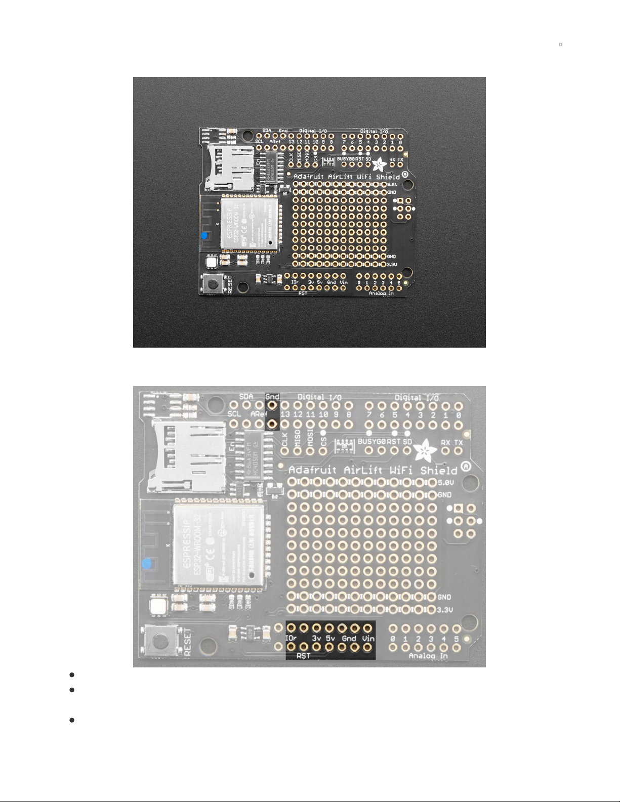
Power Pins
GND - Common power/logic ground.
3V - this is the output from the 3.3V regulator. The regulator can supply 500mA peak but half of that
is drawn by the ESP32, and it's a fairly power-hungry chip.
5V - This is the input to the regulator
© Adafruit Industries https://learn.adafruit.com/adafruit-airlift-shield-esp32-wifi-co-processor Page 8 of 56
Page 9

IOr - This is IORef, the IO voltage we will communicate with and is required.
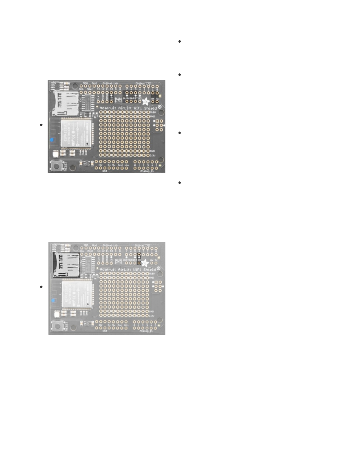
SPI Interface Pins
Both ESP32 and SD card use SPI to send and receive data. These pins are labeled CLK MISO MOSI and
have level shifting so you can use this shield with 3.3V or 5V microcontroller boards.
By default the 2x3 pin ICSP header on the right hand side is where the SPI signals are found.
ESP32 Control Pins
© Adafruit Industries https://learn.adafruit.com/adafruit-airlift-shield-esp32-wifi-co-processor Page 9 of 56
Page 10
Required Control Pins:
BUSY - this pin is an input from the AirLift, it will let us
know when its ready for more commands to be sent.
This is 3.3V logic out, can be read by 3-5V logic. This
pin
must
be connected.
RST- this pin is an output to the AirLift. Set low to put the
AirLift into reset. You should use this pin, even though
you might be able to run for a short while without it, it's
essential to 'kick' the chip if it ever gets into a locked up
state. Level shifted so can be 3-5V logic
Optional Control Pins:
GPIO0 - this is the ESP32 GPIO0 pin, which is used to
put it into bootloading mode. It is also used if you like
when the ESP32 is acting as a server, to let you know
data is ready for reading. IIt's not required for WiFi, but
you'll need to connect it to use BLE mode. Solder the
pad on the bottom of the shield to connect it.
RX & TX - Serial data in and Serial data out, used for
bootloading new firmware, and for communication when
in BLE mode. Leave disconnected if not using BLE or
when not uploading new WiFi firmware to the AirLift
(which is a rare occurrence). You'll need to solder the
two pads on the bottom of the shield to use these pins.
SD Card Interface
There's a lot of space available on this shield so we also stuck
on a micro SD card holder, great for datalogging or storing
data to transmit over WiFi.
In addition to the shared SPI pins, the SD (chip select) pin is
also used. It can be re-assigned to any pin by cutting the trace
underneath the board and rewiring. If the SD card is not used,
the SD pin can be used for any other purpose
LEDs
© Adafruit Industries https://learn.adafruit.com/adafruit-airlift-shield-esp32-wifi-co-processor Page 10 of 56
Page 11
There is a small RGB LED to the left of the ESP32. These RGB
LEDs are available in the Arduino and CircuitPython libraries if
you'd like to PWM them for a visual alert. They're connected
to the ESP32's pins 26 (Red), 25 (Green), and 27 (Blue).
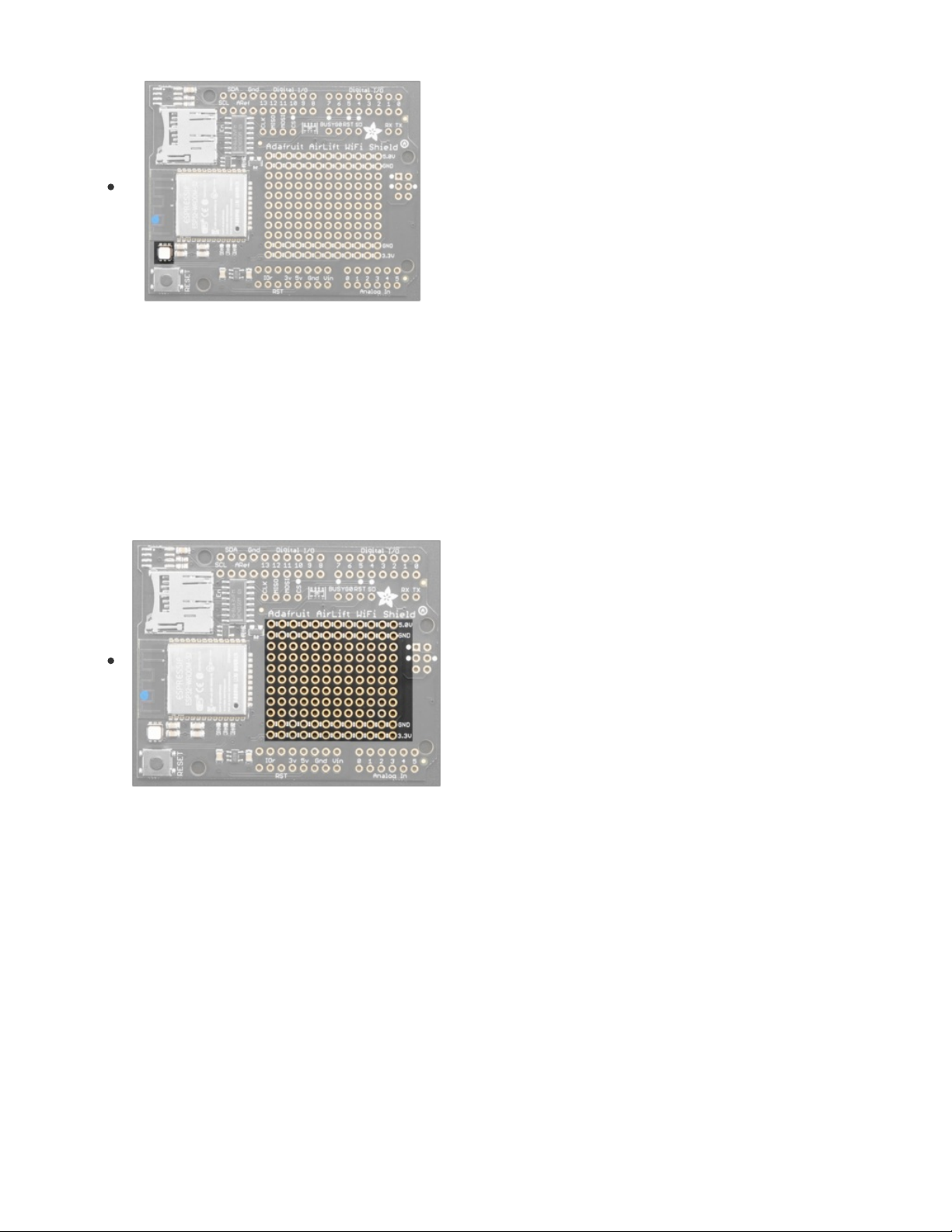
Prototyping Area
We have a big grid of prototyping holes and power rails if you
want to make some custom circuitry!
© Adafruit Industries https://learn.adafruit.com/adafruit-airlift-shield-esp32-wifi-co-processor Page 11 of 56
Page 12
Assembly
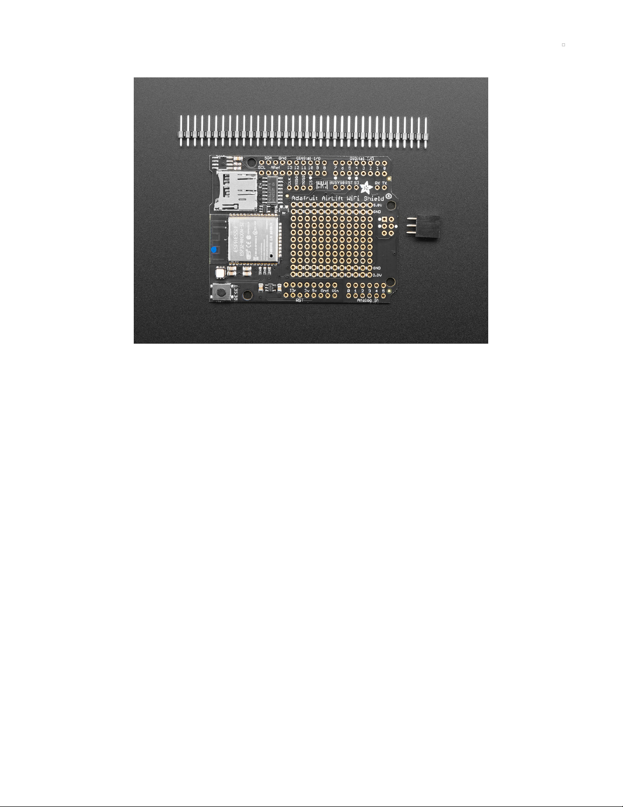
Installing Standard Headers
The shield comes with 0.1" standard header. Standard header does not permit stacking but it is
mechanically stronger and they're much less expensive too! If you want to stack a shield on top, do not
perform this step as it is not possible to uninstall the headers once soldered in! Skip down to the bottom
for the stacking tutorial
© Adafruit Industries https://learn.adafruit.com/adafruit-airlift-shield-esp32-wifi-co-processor Page 12 of 56
Page 13
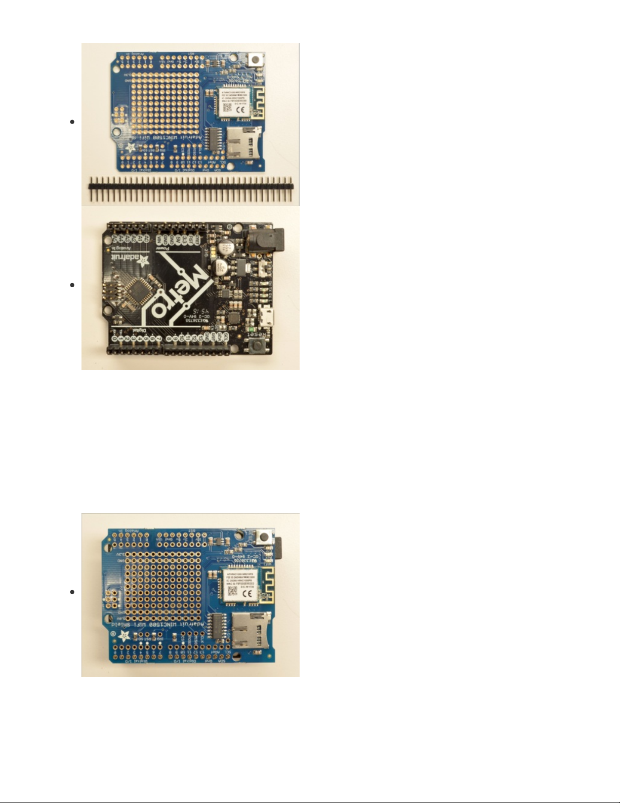
Break apart the 0.1" header into 6, 8 and/or 10-pin long pieces
and slip the long ends into the headers of your Arduino.
Place the assembled shield on top of the header-ed Arduino
so that all of the short parts of the header are sticking through
the outer set of pads
© Adafruit Industries https://learn.adafruit.com/adafruit-airlift-shield-esp32-wifi-co-processor Page 13 of 56
Page 14
Solder each one of the pins into the shield to make a secure
connection
© Adafruit Industries https://learn.adafruit.com/adafruit-airlift-shield-esp32-wifi-co-processor Page 14 of 56
Page 15

That's it! Now you can install the 2x3 header
© Adafruit Industries https://learn.adafruit.com/adafruit-airlift-shield-esp32-wifi-co-processor Page 15 of 56
Page 16
Solder the 2x3 header so that it's pointing downwards
Stack Alert!
If you want to stack a shield on top of the WiFi Shield, you'll want to pick up some stacking headers and
use those instead of the plain header shown here!
© Adafruit Industries https://learn.adafruit.com/adafruit-airlift-shield-esp32-wifi-co-processor Page 16 of 56
Page 17
Wanna stack? This tutorial shows how to use the plain header
to connect to an Arduino. If you want to use stacking
headers (https://adafru.it/dsu), don't follow these steps!
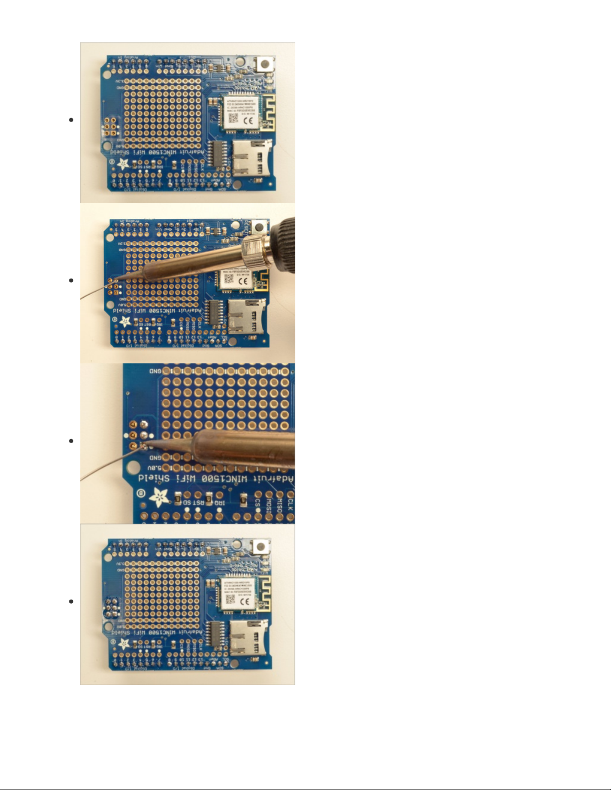
Start by sliding the 10 pin, 2 x 8 pin and 6-pin stacking
headers into the outer rows of the shield from the top. Then
flip the board over so its resting on the four headers. Pull on
the legs if necessary to straighten them out.
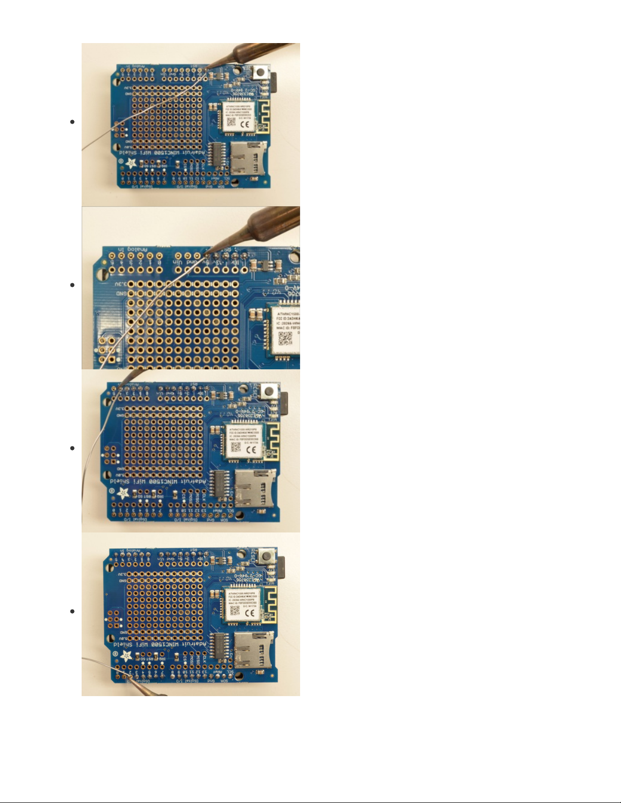
Tack one pin of each header, to get them set in place before
more soldering. If the headers go crooked you can re-heat the
one pin while re-positioning to straighten them up
© Adafruit Industries https://learn.adafruit.com/adafruit-airlift-shield-esp32-wifi-co-processor Page 17 of 56
Page 18

Once you've tacked and straightened all the headers, go back
and solder the remaining pins for each header.
© Adafruit Industries https://learn.adafruit.com/adafruit-airlift-shield-esp32-wifi-co-processor Page 18 of 56
Page 19

Insert the 2x3 stacking header as shown.
Solder into place.
© Adafruit Industries https://learn.adafruit.com/adafruit-airlift-shield-esp32-wifi-co-processor Page 19 of 56
Page 20

© Adafruit Industries https://learn.adafruit.com/adafruit-airlift-shield-esp32-wifi-co-processor Page 20 of 56
Page 21

CircuitPython WiFi
It's easy to use the Adafruit AirLift breakout with CircuitPython and the Adafruit CircuitPython
ESP32SPI (https://adafru.it/DWV) module. This module allows you to easily add WiFi to your project.
The ESP32SPI library requires a microcontroller with ~128KB of RAM or more. The SAMD21 will not
work.
CircuitPython Microcontroller Pinout
To use the board's pins with the AirLift shield, copy the following lines into your code:
esp32_cs = DigitalInOut(board.D10)
esp32_ready = DigitalInOut(board.D7)
esp32_reset = DigitalInOut(board.D5)
If you wish to use the GPIO0 pin on the ESP32 - solder the jumper on the back of the shield, highlighted
below:
Then, include the following code to use the pin:
esp32_gpio0 = DigitalInOut(board.D6)
CircuitPython Installation of ESP32SPI Library
You'll need to install the Adafruit CircuitPython ESP32SPI (https://adafru.it/DWV) library on your
CircuitPython board.
First make sure you are running the latest version of Adafruit CircuitPython (https://adafru.it/Amd) for your
© Adafruit Industries https://learn.adafruit.com/adafruit-airlift-shield-esp32-wifi-co-processor Page 21 of 56
Page 22

board.
Next you'll need to install the necessary libraries to use the hardware--carefully follow the steps to find and
install these libraries from Adafruit's CircuitPython library bundle (https://adafru.it/uap). Our CircuitPython
starter guide has a great page on how to install the library bundle (https://adafru.it/ABU).
You can manually install the necessary libraries from the bundle:
adafruit_esp32spi
adafruit_requests.mpy
adafruit_bus_device
Before continuing make sure your board's lib folder or root filesystem has the adafruit_esp32spi,
adafruit_requests.mpy, and adafruit_bus_device files and folders copied over.
Next make sure you are set up to connect to the serial console (https://adafru.it/Bec)
CircuitPython Usage
Copy the following code to your code.py file on your microcontroller:
import board
import busio
from digitalio import DigitalInOut
from adafruit_esp32spi import adafruit_esp32spi
print("ESP32 SPI hardware test")
esp32_cs = DigitalInOut(board.D10)
esp32_ready = DigitalInOut(board.D7)
esp32_reset = DigitalInOut(board.D5)
spi = busio.SPI(board.SCK, board.MOSI, board.MISO)
esp = adafruit_esp32spi.ESP_SPIcontrol(spi, esp32_cs, esp32_ready, esp32_reset)
if esp.status == adafruit_esp32spi.WL_IDLE_STATUS:
print("ESP32 found and in idle mode")
print("Firmware vers.", esp.firmware_version)
print("MAC addr:", [hex(i) for i in esp.MAC_address])
for ap in esp.scan_networks():
print("\t%s\t\tRSSI: %d" % (str(ap['ssid'], 'utf-8'), ap['rssi']))
print("Done!")
Connect to the serial console (https://adafru.it/BlO) to see the output. It should look something like the
following:
© Adafruit Industries https://learn.adafruit.com/adafruit-airlift-shield-esp32-wifi-co-processor Page 22 of 56
Page 23

Make sure you see the same output! If you don't, check your wiring. Note that we've changed the pinout in
the code example above to reflect the CircuitPython Microcontroller Pinout at the top of this page.
Once you've succeeded, continue onto the next page!
If you can read the Firmware and MAC address but fails on scanning SSIDs, check your power
supply, you may be running out of juice to the ESP32 and it's resetting
© Adafruit Industries https://learn.adafruit.com/adafruit-airlift-shield-esp32-wifi-co-processor Page 23 of 56
Page 24

Internet Connect!
Once you have CircuitPython setup and libraries installed we can get your board connected to the
Internet.
To get connected, you will need to start by creating a
secrets file
.
What's a secrets file?
We expect people to share tons of projects as they build CircuitPython WiFi widgets. What we want to
avoid is people accidentally sharing their passwords or secret tokens and API keys. So, we designed all
our examples to use a secrets.py file, that is in your CIRCUITPY drive, to hold secret/private/custom data.
That way you can share your main project without worrying about accidentally sharing private stuff.
Your secrets.py file should look like this:
# This file is where you keep secret settings, passwords, and tokens!
# If you put them in the code you risk committing that info or sharing it
secrets = {
'ssid' : 'home ssid',
'password' : 'my password',
'timezone' : "America/New_York", # http://worldtimeapi.org/timezones
'github_token' : 'fawfj23rakjnfawiefa',
'hackaday_token' : 'h4xx0rs3kret',
}
Inside is a python dictionary named secrets with a line for each entry. Each entry has an entry name (say
'ssid' ) and then a colon to separate it from the entry key 'home ssid' and finally a comma ,
At a minimum you'll need the ssid and password for your local WiFi setup. As you make projects you may
need more tokens and keys, just add them one line at a time. See for example other tokens such as one
for accessing github or the hackaday API. Other non-secret data like your timezone can also go here, just
cause its called secrets doesn't mean you can't have general customization data in there!
For the correct time zone string, look at http://worldtimeapi.org/timezones (https://adafru.it/EcP) and
remember that if your city is not listed, look for a city in the same time zone, for example Boston, New
York, Philadelphia, Washington DC, and Miami are all on the same time as New York.
Of course, don't share your secrets.py - keep that out of GitHub, Discord or other project-sharing sites.
Connect to WiFi
OK now you have your secrets setup - you can connect to the Internet using the ESP32SPI and the
Requests modules.
First make sure you are running the latest version of Adafruit CircuitPython (https://adafru.it/Amd) for your
board.
Next you'll need to install the necessary libraries to use the hardware--carefully follow the steps to find and
install these libraries from Adafruit's CircuitPython library bundle (https://adafru.it/zdx). Our introduction
guide has a great page on how to install the library bundle (https://adafru.it/ABU) for both express and
non-express boards.
© Adafruit Industries https://learn.adafruit.com/adafruit-airlift-shield-esp32-wifi-co-processor Page 24 of 56
Page 25

Remember for non-express boards like the, you'll need to manually install the necessary libraries from the
bundle:
adafruit_bus_device
adafruit_esp32_spi
adafruit_requests
neopixel
Before continuing make sure your board's lib folder or root filesystem has the above files copied over.
Next connect to the board's serial REPL (https://adafru.it/Awz) so you are at the CircuitPython >>> prompt.
Into your lib folder. Once that's done, load up the following example using Mu or your favorite editor:
# SPDX-FileCopyrightText: 2019 ladyada for Adafruit Industries
# SPDX-License-Identifier: MIT
import board
import busio
from digitalio import DigitalInOut
import adafruit_requests as requests
import adafruit_esp32spi.adafruit_esp32spi_socket as socket
from adafruit_esp32spi import adafruit_esp32spi
# Get wifi details and more from a secrets.py file
try:
from secrets import secrets
except ImportError:
print("WiFi secrets are kept in secrets.py, please add them there!")
raise
print("ESP32 SPI webclient test")
TEXT_URL = "http://wifitest.adafruit.com/testwifi/index.html"
JSON_URL = "http://api.coindesk.com/v1/bpi/currentprice/USD.json"
# If you are using a board with pre-defined ESP32 Pins:
esp32_cs = DigitalInOut(board.ESP_CS)
esp32_ready = DigitalInOut(board.ESP_BUSY)
esp32_reset = DigitalInOut(board.ESP_RESET)
# If you have an AirLift Shield:
# esp32_cs = DigitalInOut(board.D10)
# esp32_ready = DigitalInOut(board.D7)
# esp32_reset = DigitalInOut(board.D5)
# If you have an AirLift Featherwing or ItsyBitsy Airlift:
# esp32_cs = DigitalInOut(board.D13)
# esp32_ready = DigitalInOut(board.D11)
# esp32_reset = DigitalInOut(board.D12)
# If you have an externally connected ESP32:
# NOTE: You may need to change the pins to reflect your wiring
# esp32_cs = DigitalInOut(board.D9)
# esp32_ready = DigitalInOut(board.D10)
# esp32_reset = DigitalInOut(board.D5)
spi = busio.SPI(board.SCK, board.MOSI, board.MISO)
esp = adafruit_esp32spi.ESP_SPIcontrol(spi, esp32_cs, esp32_ready, esp32_reset)
© Adafruit Industries https://learn.adafruit.com/adafruit-airlift-shield-esp32-wifi-co-processor Page 25 of 56
Page 26

requests.set_socket(socket, esp)
if esp.status == adafruit_esp32spi.WL_IDLE_STATUS:
print("ESP32 found and in idle mode")
print("Firmware vers.", esp.firmware_version)
print("MAC addr:", [hex(i) for i in esp.MAC_address])
for ap in esp.scan_networks():
print("\t%s\t\tRSSI: %d" % (str(ap["ssid"], "utf-8"), ap["rssi"]))
print("Connecting to AP...")
while not esp.is_connected:
try:
esp.connect_AP(secrets["ssid"], secrets["password"])
except RuntimeError as e:
print("could not connect to AP, retrying: ", e)
continue
print("Connected to", str(esp.ssid, "utf-8"), "\tRSSI:", esp.rssi)
print("My IP address is", esp.pretty_ip(esp.ip_address))
print(
"IP lookup adafruit.com: %s" % esp.pretty_ip(esp.get_host_by_name("adafruit.com"))
)
print("Ping google.com: %d ms" % esp.ping("google.com"))
# esp._debug = True
print("Fetching text from", TEXT_URL)
r = requests.get(TEXT_URL)
print("-" * 40)
print(r.text)
print("-" * 40)
r.close()
print()
print("Fetching json from", JSON_URL)
r = requests.get(JSON_URL)
print("-" * 40)
print(r.json())
print("-" * 40)
r.close()
print("Done!")
And save it to your board, with the name code.py .
You may need to change the esp32_cs, esp32_ready and esp32_reset pins in the code to match
your hardware's pinout.
Then go down to this line
esp.connect_AP(b'MY_SSID_NAME', b'MY_SSID_PASSWORD')
and change MY_SSID_NAME and MY_SSID_PASSWORD to your access point name and password,
keeping them within the '' quotes. (This example doesn't use the secrets' file, but its also very stand-alone
so if other things seem to not work you can always re-load this. You should get something like the
following:
© Adafruit Industries https://learn.adafruit.com/adafruit-airlift-shield-esp32-wifi-co-processor Page 26 of 56
Page 27

In order, the example code...
Initializes the ESP32 over SPI using the SPI port and 3 control pins:
esp32_cs = DigitalInOut(board.ESP_CS)
esp32_ready = DigitalInOut(board.ESP_BUSY)
esp32_reset = DigitalInOut(board.ESP_RESET)
spi = busio.SPI(board.SCK, board.MOSI, board.MISO)
esp = adafruit_esp32spi.ESP_SPIcontrol(spi, esp32_cs, esp32_ready, esp32_reset)
Tells our requests library the type of socket we're using (socket type varies by connectivity type - we'll be
using the adafruit_esp32spi_socket for this example). We'll also set the interface to an esp object. This is a
little bit of a hack, but it lets us use requests like CPython does.
requests.set_socket(socket, esp)
Verifies an ESP32 is found, checks the firmware and MAC address
if esp.status == adafruit_esp32spi.WL_IDLE_STATUS:
print("ESP32 found and in idle mode")
print("Firmware vers.", esp.firmware_version)
print("MAC addr:", [hex(i) for i in esp.MAC_address])
Performs a scan of all access points it can see and prints out the name and signal strength:
© Adafruit Industries https://learn.adafruit.com/adafruit-airlift-shield-esp32-wifi-co-processor Page 27 of 56
Page 28

for ap in esp.scan_networks():
print("\t%s\t\tRSSI: %d" % (str(ap['ssid'], 'utf-8'), ap['rssi']))
Connects to the AP we've defined here, then prints out the local IP address, attempts to do a domain
name lookup and ping google.com to check network connectivity (note sometimes the ping fails or takes
a while, this isn't a big deal)
print("Connecting to AP...")
esp.connect_AP(b'MY_SSID_NAME', b'MY_SSID_PASSWORD')
print("Connected to", str(esp.ssid, 'utf-8'), "\tRSSI:", esp.rssi)
print("My IP address is", esp.pretty_ip(esp.ip_address))
print("IP lookup adafruit.com: %s" % esp.pretty_ip(esp.get_host_by_name("adafruit.com")))
print("Ping google.com: %d ms" % esp.ping("google.com"))
OK now we're getting to the really interesting part. With a SAMD51 or other large-RAM (well, over 32 KB)
device, we can do a lot of neat tricks. Like for example we can implement an interface a lot like
requests (https://adafru.it/E9o) - which makes getting data
really really easy
To read in all the text from a web URL call requests.get - you can pass in https URLs for SSL connectivity
TEXT_URL = "http://wifitest.adafruit.com/testwifi/index.html"
print("Fetching text from", TEXT_URL)
r = requests.get(TEXT_URL)
print('-'*40)
print(r.text)
print('-'*40)
r.close()
Or, if the data is in structured JSON, you can get the json pre-parsed into a Python dictionary that can be
easily queried or traversed. (Again, only for nRF52840, M4 and other high-RAM boards)
JSON_URL = "http://api.coindesk.com/v1/bpi/currentprice/USD.json"
print("Fetching json from", JSON_URL)
r = requests.get(JSON_URL)
print('-'*40)
print(r.json())
print('-'*40)
r.close()
Requests
We've written a requests-like (https://adafru.it/Kpa) library for web interfacing
named Adafruit_CircuitPython_Requests (https://adafru.it/FpW). This library allows you to send HTTP/1.1
requests without "crafting" them and provides helpful methods for parsing the response from the server.
Here's an example of using Requests to perform GET and POST requests to a server.
# SPDX-FileCopyrightText: 2021 ladyada for Adafruit Industries
# SPDX-License-Identifier: MIT
# adafruit_requests usage with an esp32spi_socket
import board
import busio
from digitalio import DigitalInOut
import adafruit_esp32spi.adafruit_esp32spi_socket as socket
© Adafruit Industries https://learn.adafruit.com/adafruit-airlift-shield-esp32-wifi-co-processor Page 28 of 56
Page 29

from adafruit_esp32spi import adafruit_esp32spi
import adafruit_requests as requests
# Add a secrets.py to your filesystem that has a dictionary called secrets with "ssid" and
# "password" keys with your WiFi credentials. DO NOT share that file or commit it into Git or other
# source control.
# pylint: disable=no-name-in-module,wrong-import-order
try:
from secrets import secrets
except ImportError:
print("WiFi secrets are kept in secrets.py, please add them there!")
raise
# If you are using a board with pre-defined ESP32 Pins:
esp32_cs = DigitalInOut(board.ESP_CS)
esp32_ready = DigitalInOut(board.ESP_BUSY)
esp32_reset = DigitalInOut(board.ESP_RESET)
# If you have an externally connected ESP32:
# esp32_cs = DigitalInOut(board.D9)
# esp32_ready = DigitalInOut(board.D10)
# esp32_reset = DigitalInOut(board.D5)
spi = busio.SPI(board.SCK, board.MOSI, board.MISO)
esp = adafruit_esp32spi.ESP_SPIcontrol(spi, esp32_cs, esp32_ready, esp32_reset)
print("Connecting to AP...")
while not esp.is_connected:
try:
esp.connect_AP(secrets["ssid"], secrets["password"])
except RuntimeError as e:
print("could not connect to AP, retrying: ", e)
continue
print("Connected to", str(esp.ssid, "utf-8"), "\tRSSI:", esp.rssi)
# Initialize a requests object with a socket and esp32spi interface
socket.set_interface(esp)
requests.set_socket(socket, esp)
TEXT_URL = "http://wifitest.adafruit.com/testwifi/index.html"
JSON_GET_URL = "http://httpbin.org/get"
JSON_POST_URL = "http://httpbin.org/post"
print("Fetching text from %s" % TEXT_URL)
response = requests.get(TEXT_URL)
print("-" * 40)
print("Text Response: ", response.text)
print("-" * 40)
response.close()
print("Fetching JSON data from %s" % JSON_GET_URL)
response = requests.get(JSON_GET_URL)
print("-" * 40)
print("JSON Response: ", response.json())
print("-" * 40)
response.close()
data = "31F"
print("POSTing data to {0}: {1}".format(JSON_POST_URL, data))
response = requests.post(JSON_POST_URL, data=data)
print("-" * 40)
© Adafruit Industries https://learn.adafruit.com/adafruit-airlift-shield-esp32-wifi-co-processor Page 29 of 56
Page 30

json_resp = response.json()
# Parse out the 'data' key from json_resp dict.
print("Data received from server:", json_resp["data"])
print("-" * 40)
response.close()
json_data = {"Date": "July 25, 2019"}
print("POSTing data to {0}: {1}".format(JSON_POST_URL, json_data))
response = requests.post(JSON_POST_URL, json=json_data)
print("-" * 40)
json_resp = response.json()
# Parse out the 'json' key from json_resp dict.
print("JSON Data received from server:", json_resp["json"])
print("-" * 40)
response.close()
The code first sets up the ESP32SPI interface. Then, it initializes a request object using an ESP32 socket
and the esp object.
import board
import busio
from digitalio import DigitalInOut
import adafruit_esp32spi.adafruit_esp32spi_socket as socket
from adafruit_esp32spi import adafruit_esp32spi
import adafruit_requests as requests
# If you have an externally connected ESP32:
esp32_cs = DigitalInOut(board.D9)
esp32_ready = DigitalInOut(board.D10)
esp32_reset = DigitalInOut(board.D5)
spi = busio.SPI(board.SCK, board.MOSI, board.MISO)
esp = adafruit_esp32spi.ESP_SPIcontrol(spi, esp32_cs, esp32_ready, esp32_reset)
print("Connecting to AP...")
while not esp.is_connected:
try:
esp.connect_AP(b'MY_SSID_NAME', b'MY_SSID_PASSWORD')
except RuntimeError as e:
print("could not connect to AP, retrying: ",e)
continue
print("Connected to", str(esp.ssid, 'utf-8'), "\tRSSI:", esp.rssi)
# Initialize a requests object with a socket and esp32spi interface
requests.set_socket(socket, esp)
Make sure to set the ESP32 pinout to match your AirLift breakout's connection:
esp32_cs = DigitalInOut(board.D9)
esp32_ready = DigitalInOut(board.D10)
esp32_reset = DigitalInOut(board.D5)
HTTP GET with Requests
The code makes a HTTP GET request to Adafruit's WiFi testing website
- http://wifitest.adafruit.com/testwifi/index.html (https://adafru.it/FpZ).
To do this, we'll pass the URL into requests.get() . We're also going to save the response
from
the server
© Adafruit Industries https://learn.adafruit.com/adafruit-airlift-shield-esp32-wifi-co-processor Page 30 of 56
Page 31

into a variable named response .
While we requested data from the server, we'd what the server responded with. Since we already saved
the server's response , we can read it back. Luckily for us, requests automatically decodes the server's
response into human-readable text, you can read it back by calling response.text .
Lastly, we'll perform a bit of cleanup by calling response.close() . This closes, deletes, and collect's the
response's data.
print("Fetching text from %s"%TEXT_URL)
response = requests.get(TEXT_URL)
print('-'*40)
print("Text Response: ", response.text)
print('-'*40)
response.close()
While some servers respond with text, some respond with json-formatted data consisting of attribute–
value pairs.
CircuitPython_Requests can convert a JSON-formatted response from a server into a CPython dict.
object.
We can also fetch and parse json data. We'll send a HTTP get to a url we know returns a json-formatted
response (instead of text data).
Then, the code calls response.json() to convert the response to a CPython dict .
print("Fetching JSON data from %s"%JSON_GET_URL)
response = requests.get(JSON_GET_URL)
print('-'*40)
print("JSON Response: ", response.json())
print('-'*40)
response.close()
HTTP POST with Requests
Requests can also POST data to a server by calling the requests.post method, passing it a data value.
data = '31F'
print("POSTing data to {0}: {1}".format(JSON_POST_URL, data))
response = requests.post(JSON_POST_URL, data=data)
print('-'*40)
json_resp = response.json()
# Parse out the 'data' key from json_resp dict.
print("Data received from server:", json_resp['data'])
print('-'*40)
response.close()
You can also post json-formatted data to a server by passing json data into the requests.post method.
© Adafruit Industries https://learn.adafruit.com/adafruit-airlift-shield-esp32-wifi-co-processor Page 31 of 56
Page 32

json_data = {"Date" : "July 25, 2019"}
print("POSTing data to {0}: {1}".format(JSON_POST_URL, json_data))
response = requests.post(JSON_POST_URL, json=json_data)
print('-'*40)
json_resp = response.json()
# Parse out the 'json' key from json_resp dict.
print("JSON Data received from server:", json_resp['json'])
print('-'*40)
response.close()
Advanced Requests Usage
Want to send custom HTTP headers, parse the response as raw bytes, or handle a response's http status
code in your CircuitPython code?
We've written an example to show advanced usage of the requests module below.
# SPDX-FileCopyrightText: 2021 ladyada for Adafruit Industries
# SPDX-License-Identifier: MIT
import board
import busio
from digitalio import DigitalInOut
import adafruit_esp32spi.adafruit_esp32spi_socket as socket
from adafruit_esp32spi import adafruit_esp32spi
import adafruit_requests as requests
# Add a secrets.py to your filesystem that has a dictionary called secrets with "ssid" and
# "password" keys with your WiFi credentials. DO NOT share that file or commit it into Git or other
# source control.
# pylint: disable=no-name-in-module,wrong-import-order
try:
from secrets import secrets
except ImportError:
print("WiFi secrets are kept in secrets.py, please add them there!")
raise
# If you are using a board with pre-defined ESP32 Pins:
esp32_cs = DigitalInOut(board.ESP_CS)
esp32_ready = DigitalInOut(board.ESP_BUSY)
esp32_reset = DigitalInOut(board.ESP_RESET)
# If you have an externally connected ESP32:
# esp32_cs = DigitalInOut(board.D9)
# esp32_ready = DigitalInOut(board.D10)
# esp32_reset = DigitalInOut(board.D5)
spi = busio.SPI(board.SCK, board.MOSI, board.MISO)
esp = adafruit_esp32spi.ESP_SPIcontrol(spi, esp32_cs, esp32_ready, esp32_reset)
print("Connecting to AP...")
while not esp.is_connected:
try:
esp.connect_AP(secrets["ssid"], secrets["password"])
except RuntimeError as e:
print("could not connect to AP, retrying: ", e)
continue
print("Connected to", str(esp.ssid, "utf-8"), "\tRSSI:", esp.rssi)
# Initialize a requests object with a socket and esp32spi interface
© Adafruit Industries https://learn.adafruit.com/adafruit-airlift-shield-esp32-wifi-co-processor Page 32 of 56
Page 33

socket.set_interface(esp)
requests.set_socket(socket, esp)
JSON_GET_URL = "http://httpbin.org/get"
# Define a custom header as a dict.
headers = {"user-agent": "blinka/1.0.0"}
print("Fetching JSON data from %s..." % JSON_GET_URL)
response = requests.get(JSON_GET_URL, headers=headers)
print("-" * 60)
json_data = response.json()
headers = json_data["headers"]
print("Response's Custom User-Agent Header: {0}".format(headers["User-Agent"]))
print("-" * 60)
# Read Response's HTTP status code
print("Response HTTP Status Code: ", response.status_code)
print("-" * 60)
# Close, delete and collect the response data
response.close()
WiFi Manager
That simpletest example works but its a little finicky - you need to constantly check WiFi status and have
many loops to manage connections and disconnections. For more advanced uses, we recommend using
the WiFiManager object. It will wrap the connection/status/requests loop for you - reconnecting if WiFi
drops, resetting the ESP32 if it gets into a bad state, etc.
Here's a more advanced example that shows the WiFi manager and also how to POST data with some
extra headers:
# SPDX-FileCopyrightText: 2019 ladyada for Adafruit Industries
# SPDX-License-Identifier: MIT
import time
import board
import busio
from digitalio import DigitalInOut
import neopixel
from adafruit_esp32spi import adafruit_esp32spi
from adafruit_esp32spi import adafruit_esp32spi_wifimanager
print("ESP32 SPI webclient test")
# Get wifi details and more from a secrets.py file
try:
from secrets import secrets
except ImportError:
print("WiFi secrets are kept in secrets.py, please add them there!")
raise
# If you are using a board with pre-defined ESP32 Pins:
esp32_cs = DigitalInOut(board.ESP_CS)
esp32_ready = DigitalInOut(board.ESP_BUSY)
esp32_reset = DigitalInOut(board.ESP_RESET)
# If you have an externally connected ESP32:
# esp32_cs = DigitalInOut(board.D9)
© Adafruit Industries https://learn.adafruit.com/adafruit-airlift-shield-esp32-wifi-co-processor Page 33 of 56
Page 34

# esp32_ready = DigitalInOut(board.D10)
# esp32_reset = DigitalInOut(board.D5)
spi = busio.SPI(board.SCK, board.MOSI, board.MISO)
esp = adafruit_esp32spi.ESP_SPIcontrol(spi, esp32_cs, esp32_ready, esp32_reset)
"""Use below for Most Boards"""
status_light = neopixel.NeoPixel(
board.NEOPIXEL, 1, brightness=0.2
) # Uncomment for Most Boards
"""Uncomment below for ItsyBitsy M4"""
# status_light = dotstar.DotStar(board.APA102_SCK, board.APA102_MOSI, 1, brightness=0.2)
# Uncomment below for an externally defined RGB LED
# import adafruit_rgbled
# from adafruit_esp32spi import PWMOut
# RED_LED = PWMOut.PWMOut(esp, 26)
# GREEN_LED = PWMOut.PWMOut(esp, 27)
# BLUE_LED = PWMOut.PWMOut(esp, 25)
# status_light = adafruit_rgbled.RGBLED(RED_LED, BLUE_LED, GREEN_LED)
wifi = adafruit_esp32spi_wifimanager.ESPSPI_WiFiManager(esp, secrets, status_light)
counter = 0
while True:
try:
print("Posting data...", end="")
data = counter
feed = "test"
payload = {"value": data}
response = wifi.post(
"https://io.adafruit.com/api/v2/"
+ secrets["aio_username"]
+ "/feeds/"
+ feed
+ "/data",
json=payload,
headers={"X-AIO-KEY": secrets["aio_key"]},
)
print(response.json())
response.close()
counter = counter + 1
print("OK")
except (ValueError, RuntimeError) as e:
print("Failed to get data, retrying\n", e)
wifi.reset()
continue
response = None
time.sleep(15)
You'll note here we use a secrets.py file to manage our SSID info. The wifimanager is given the ESP32
object, secrets and a neopixel for status indication.
Note, you'll need to add a some additional information to your secrets file so that the code can query the
Adafruit IO API:
aio_username
aio_key
You can go to your adafruit.io View AIO Key link to get those two values and add them to the secrets file,
which will now look something like this:
© Adafruit Industries https://learn.adafruit.com/adafruit-airlift-shield-esp32-wifi-co-processor Page 34 of 56
Page 35

# This file is where you keep secret settings, passwords, and tokens!
# If you put them in the code you risk committing that info or sharing it
secrets = {
'ssid' : '_your_ssid_',
'password' : '_your_wifi_password_',
'timezone' : "America/Los_Angeles", # http://worldtimeapi.org/timezones
'aio_username' : '_your_aio_username_',
'aio_key' : '_your_aio_key_',
}
Next, set up an Adafruit IO feed named test
If you do not know how to set up a feed, follow this page and come back when you've set up a feed
named test . (https://adafru.it/f5k)
We can then have a simple loop for posting data to Adafruit IO without having to deal with connecting or
initializing the hardware!
Take a look at your test feed on Adafruit.io and you'll see the value increase each time the CircuitPython
board posts data to it!
© Adafruit Industries https://learn.adafruit.com/adafruit-airlift-shield-esp32-wifi-co-processor Page 35 of 56
Page 36

CircuitPython BLE
CircuitPython BLE UART Example
It's easy to use Adafruit AirLift ESP32 co-processor boards for Bluetooth Low Energy (BLE) with
CircuitPython. When you reset the ESP32, you can put it in WiFi mode (the default), or in BLE mode; you
cannot use both modes simultaenously.
Here's a simple example of using BLE to connect CircuitPython with the Bluefruit Connect app. Use
CircuitPython 6.0.0 or later.
Note: Don't confuse the ESP32 with the ESP32-S2, which is a different module with a similar name. The
ESP32-S2 does not support BLE.
Currently the AirLift support for CircuitPython only provides BLE peripheral support. BLE central is
under development. So you cannot connect to BLE devices like Heart Rate monitors, etc., but you can
act as a BLE peripheral yourself.
Adafruit AirLift ESP32 Shield Wiring
If you have an Adafruit AirLift ESP32 Shield, you will need to solder three jumpers closed on the bottom
side of the board to enable BLE. The rest of the ESP32 pins you need are already jumpered to certain
shield pins.
Update the AirLift Firmware
You will need to update the AirLift's firmware to at least version 1.7.1. Previous versions of the AirLift
firmware do not support BLE.
Follow the instructions in the guide below, and come back to this page when you've upgraded the AirLift's
firmware:
https://adafru.it/RdC
Ensure the AirLift firmware is version 1.7.1 or higher for BLE to work.
Install CircuitPython Libraries
Make sure you are running the latest version of Adafruit CircuitPython (https://adafru.it/Amd) for your
board; you'll need 6.0.0 or later.
Next you'll need to install the necessary libraries to use the hardware and BLE. Carefully follow the steps
to find and install these libraries from Adafruit's CircuitPython library bundle (https://adafru.it/uap). Our
CircuitPython starter guide has a great page on how to use the library bundle (https://adafru.it/ABU).
Install these libraries from the bundle:
adafruit_airlift
adafruit_ble
https://adafru.it/RdC
© Adafruit Industries https://learn.adafruit.com/adafruit-airlift-shield-esp32-wifi-co-processor Page 36 of 56
Page 37

Before continuing make sure your board's lib folder or root filesystem has the adafruit_airlift and
adafruit_ble folders copied over.
Install the Adafruit Bluefruit LE Connect App
The Adafruit Bluefruit LE Connect iOS and Android apps allow you to connect to BLE peripherals that
provide a over-the-air "UART" service. Follow the instructions in the Bluefruit LE Connect
Guide (https://adafru.it/Eg5) to download and install the app on your phone or tablet.
Copy and Adjust the Example Program
Copy the program below to the file code.py on CIRCUITPY on your board.
TAKE NOTE: Adjust the program as needed to suit the AirLift board you have. Comment and
uncomment lines 12-39 below as necessary.
import board
from adafruit_ble import BLERadio
from adafruit_ble.advertising.standard import ProvideServicesAdvertisement
from adafruit_ble.services.nordic import UARTService
from adafruit_airlift.esp32 import ESP32
# If you are using a Metro M4 Airlift Lite, PyPortal,
# or MatrixPortal, you can use the default pin settings.
# Leave this DEFAULT line uncommented.
esp32 = ESP32() # DEFAULT
# If you are using CircuitPython 6.0.0 or earlier,
# on PyPortal and PyPortal Titano only, use the pin settings
# below. Comment out the DEFAULT line above and uncomment
# the line below. For CircuitPython 6.1.0, the pin names
# have changed for these boards, and the DEFAULT line
# above is correct.
# esp32 = ESP32(tx=board.TX, rx=board.RX)
# If you are using an AirLift FeatherWing or AirLift Bitsy Add-On,
# use the pin settings below. Comment out the DEFAULT line above
# and uncomment the lines below.
# If you are using an AirLift Breakout, check that these
# choices match the wiring to your microcontroller board,
# or change them as appropriate.
# esp32 = ESP32(
# reset=board.D12,
# gpio0=board.D10,
# busy=board.D11,
# chip_select=board.D13,
# tx=board.TX,
# rx=board.RX,
# )
# If you are using an AirLift Shield,
# use the pin settings below. Comment out the DEFAULT line above
# and uncomment the lines below.
# esp32 = ESP32(
# reset=board.D5,
# gpio0=board.D6,
# busy=board.D7,
# chip_select=board.D10,
# tx=board.TX,
© Adafruit Industries https://learn.adafruit.com/adafruit-airlift-shield-esp32-wifi-co-processor Page 37 of 56
Page 38

# tx=board.TX,
# rx=board.RX,
# )
adapter = esp32.start_bluetooth()
ble = BLERadio(adapter)
uart = UARTService()
advertisement = ProvideServicesAdvertisement(uart)
while True:
ble.start_advertising(advertisement)
print("waiting to connect")
while not ble.connected:
pass
print("connected: trying to read input")
while ble.connected:
# Returns b'' if nothing was read.
one_byte = uart.read(1)
if one_byte:
print(one_byte)
uart.write(one_byte)
Talk to the AirLift via the Bluefruit LE Connect App
Start the Bluefruit LE Connect App on your phone or tablet. You should see a CIRCUITPY device available
to connect to. Tap the Connect button (1):
You'll then see a list of Bluefruit Connect functions ("modules"). Choose the UART module (2):
© Adafruit Industries https://learn.adafruit.com/adafruit-airlift-shield-esp32-wifi-co-processor Page 38 of 56
Page 39

On the UART module page, you can type a string and press Send (3). You'll see that string entered, and
then see it echoed back (echoing is in gray).
© Adafruit Industries https://learn.adafruit.com/adafruit-airlift-shield-esp32-wifi-co-processor Page 39 of 56
Page 40

© Adafruit Industries https://learn.adafruit.com/adafruit-airlift-shield-esp32-wifi-co-processor Page 40 of 56
Page 41

Arduino WiFi
You can use an AirLift with Arduino. Unlike CircuitPython, it work work with just about any Arduino board,
even a classic Arduino UNO. However, if you want to use libraries like Adafruit IO Arduino, ArduinoJSON,
or add sensors and SD card, you'll really want an ATSAMD21 (Cortex M0) or ATSAMD51 (Cortex M4), both
of which have
plenty
or RAM.
Library Install
We're using a variant of the Arduino WiFiNINA library, which is amazing and written by the Arduino team!
The official WiFi101 library won't work because it doesn't support the ability to change the pins .
So! We made a fork that you can install.
Click here to download the library:
https://adafru.it/Evm
Within the Arduino IDE, select Sketch->Include Library -> Add .ZIP library...
And select the zip you just downloaded.
First Test
OK now you have it wired and library installed, time to test it out!
Lets start by scanning the local networks. Load up the ScanNetworks example
https://adafru.it/Evm
© Adafruit Industries https://learn.adafruit.com/adafruit-airlift-shield-esp32-wifi-co-processor Page 41 of 56
Page 42

(https://adafru.it/EVu)
At the top you'll see a section where the GPIO pins are defined
(https://adafru.it/EVv)
If you don't see this, you may have the wrong WiFiNINA library installed. Uninstall it and re-install the
Adafruit one as above.
Arduino Microcontroller Pin Definition
Next, you'll need to need to modify the pin definition above for the AirLift Shield. Replace the
configuration in the sketch with the pinouts below:
#define SPIWIFI SPI // The SPI port
#define SPIWIFI_SS 10 // Chip select pin
#define ESP32_RESETN 5 // Reset pin
#define SPIWIFI_ACK 7 // a.k.a BUSY or READY pin
#define ESP32_GPIO0 6
Compile and upload to your board wired up to the AirLift
© Adafruit Industries https://learn.adafruit.com/adafruit-airlift-shield-esp32-wifi-co-processor Page 42 of 56
Page 43

(https://adafru.it/EVw)
If you don't even get the MAC address printed out, check your wiring.
If you get the MAC address but cannot scan any networks, check your power supply. You need a solid 3-
5VDC into Vin in order for the ESP32 not to brown out.
WiFi Connection Test
Now that you have your wiring checked, time to connect to the Internet!
Open up the WiFiWebClient example
(https://adafru.it/EVx)
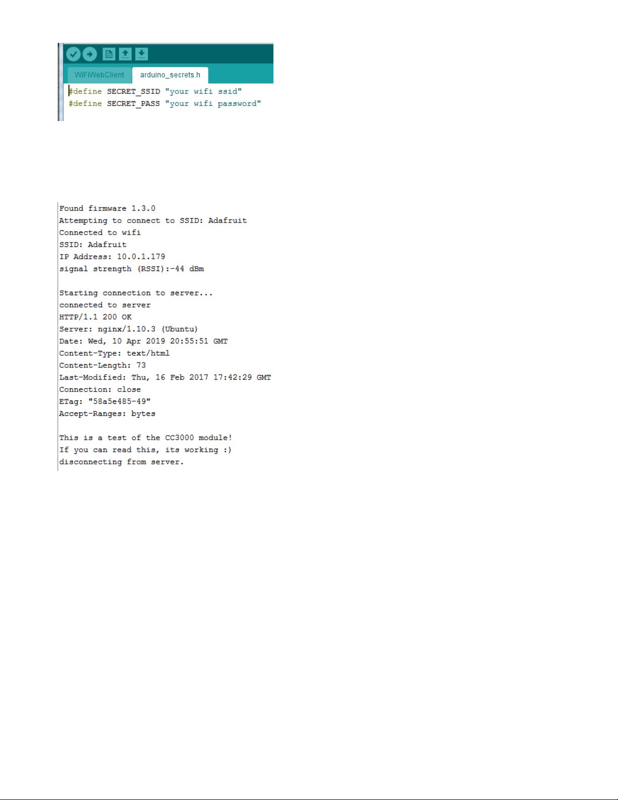
Open up the secondary tab, arduino_secrets.h. This is where you will store private data like the
SSID/password to your network.
© Adafruit Industries https://learn.adafruit.com/adafruit-airlift-shield-esp32-wifi-co-processor Page 43 of 56
Page 44
(https://adafru.it/EVy)
You must change these string values before updating to your board!
After you've set it correctly, upload and check the serial monitor. You should see the following. If not, go
back, check wiring, power and your SSID/password
(https://adafru.it/EVz)
Secure Connection Example
Many servers today do not allow non-SSL connectivity. Lucky for you the ESP32 has a great TLS/SSL stack
so you can have that all taken care of for you. Here's an example of a secure WiFi connection:
© Adafruit Industries https://learn.adafruit.com/adafruit-airlift-shield-esp32-wifi-co-processor Page 44 of 56
Page 45

(https://adafru.it/EVA)
Note we use WiFiSSLClient client; instead of WiFiClient client; to require an SSL connection!
© Adafruit Industries https://learn.adafruit.com/adafruit-airlift-shield-esp32-wifi-co-processor Page 45 of 56
Page 46

(https://adafru.it/EVB)
JSON Parsing Example
This example is a little more advanced - many sites will have API's that give you JSON data. We'll
use ArduinoJSON (https://adafru.it/Evn) to convert that to a format we can use and then display that data
on the serial port (which can then be re-directed to a display of some sort)
First up, use the Library manager to install ArduinoJSON (https://adafru.it/Evo).
Then load the example JSONdemo
© Adafruit Industries https://learn.adafruit.com/adafruit-airlift-shield-esp32-wifi-co-processor Page 46 of 56
Page 47

(https://adafru.it/EVC)
By default it will connect to to the Twitter banner image API, parse the username and followers and display
them.
(https://adafru.it/EVD)
Adapting Other Examples
Once you've got it connecting to the Internet you can check out the other examples. The only change
you'll want to make is at the top of the sketches, add:
#define SPIWIFI SPI // The SPI port
#define SPIWIFI_SS 10 // Chip select pin
#define ESP32_RESETN 5 // Reset pin
#define SPIWIFI_ACK 7 // a.k.a BUSY or READY pin
#define ESP32_GPIO0 6
And then before you check the status() of the module, call the function WiFi.setPins(SPIWIFI_SS,
SPIWIFI_ACK, ESP32_RESETN, ESP32_GPIO0, &SPIWIFI); like so:
// check for the WiFi module:
WiFi.setPins(SPIWIFI_SS, SPIWIFI_ACK, ESP32_RESETN, ESP32_GPIO0, &SPIWIFI);
while (WiFi.status() == WL_NO_MODULE) {
Serial.println("Communication with WiFi module failed!");
// don't continue
delay(1000);
}
© Adafruit Industries https://learn.adafruit.com/adafruit-airlift-shield-esp32-wifi-co-processor Page 47 of 56
Page 48

Upgrade External ESP32 Airlift Firmware
To support BLE on the ESP32 AirLift, you'll need NINA_W102-1.7.1.bin or later.
External AirLift FeatherWing, Shield, or ItsyWing
External AirLift boards have three optional ESP32 control pins which are not connected by default:
ESPGPIO0
ESPRX
ESPTX
Make sure to solder each of these pads together. You will not
be able to upload firmware to your ESP32 if they are not
connected.
© Adafruit Industries https://learn.adafruit.com/adafruit-airlift-shield-esp32-wifi-co-processor Page 48 of 56
Page 49

Upload Serial Passthrough code for Feather or ItsyBitsy
First, back up any code and files you have on your CIRCUITPY drive . It will be overwritten by the code
you're going to upload to your board. You should not end up losing any files on the QSPI flash, but it's a
good idea to back them up anyways.
This section is only for an AirLift FeatherWing with a Feather M4, or an AirLift BitsyWing with an
ItsyBitsy M4. If you are using a different hardware combination - scroll down to the "External AirLift
Breakout" section.
Download the UF2 for your board to your Desktop.
https://adafru.it/OYF
https://adafru.it/PTE
https://adafru.it/IEK
Find the reset button on your board. It's a small, black button, and on most of the boards, it will be the only
button available.
Tap this button twice to enter the bootloader. If it doesn't work on the first try, don't be discouraged. The
rhythm of the taps needs to be correct and sometimes it takes a few tries.
Once successful, the RGB LED on the board will flash red and then stay green. A new drive will show up
on your computer. The drive will be called boardnameBOOT where boardname is a reference to your
specific board. For example, a Feather will have FEATHERBOOT and a Trinket will
have TRINKETBOOT etc. Going forward we'll just call the boot drive BOOT
The board is now in bootloader mode. Now find the UF2 file you downloaded. Drag that file to the BOOT
drive on your computer in your operating system file manager/finder.
https://adafru.it/OYF
https://adafru.it/PTE
https://adafru.it/IEK
© Adafruit Industries https://learn.adafruit.com/adafruit-airlift-shield-esp32-wifi-co-processor Page 49 of 56
Page 50

The lights should flash again, BOOT will disappear. Your board should re-enumerate USB and appear as a
COM or Serial port on your computer. Make a note of the serial port by checking the Device Manager
(Windows) or typing ls /dev/cu* or /dev/tty* (Mac or Linux) in a terminal.
If your board is listed in the terminal, proceed to the Uploading nina-fw with esptool section of this guide.
External AirLift Breakout
You'll be turning your Arduino board into a USB to Serial converter. To do this, you'll need a special
Arduino sketch named SerialESPPassthrough.ino and an Arduino-compatible board with Native USB
support such as the Adafruit Metro M4.
You will also need to make the following connections between the board and the AirLift Breakout:
Board Pin 12 to ESP32_ResetN
Board Pin 10 to ESP32 GPIO0
Board TX to RXI
Board RX to TX0
Click
Download: Project ZIP
to download the code below.
/*
SerialNINAPassthrough - Use esptool to flash the ESP32 module
For use with PyPortal, Metro M4 WiFi...
Copyright (c) 2018 Arduino SA. All rights reserved.
This library is free software; you can redistribute it and/or
modify it under the terms of the GNU Lesser General Public
License as published by the Free Software Foundation; either
version 2.1 of the License, or (at your option) any later version.
This library is distributed in the hope that it will be useful,
but WITHOUT ANY WARRANTY; without even the implied warranty of
MERCHANTABILITY or FITNESS FOR A PARTICULAR PURPOSE. See the GNU
Lesser General Public License for more details.
You should have received a copy of the GNU Lesser General Public
License along with this library; if not, write to the Free Software
Foundation, Inc., 51 Franklin St, Fifth Floor, Boston, MA 02110-1301 USA
*/
#include <Adafruit_NeoPixel.h>
unsigned long baud = 115200;
© Adafruit Industries https://learn.adafruit.com/adafruit-airlift-shield-esp32-wifi-co-processor Page 50 of 56
Page 51

#if defined(ADAFRUIT_FEATHER_M4_EXPRESS) || \
defined(ADAFRUIT_FEATHER_M0_EXPRESS) || \
defined(ARDUINO_AVR_FEATHER32U4) || \
defined(ARDUINO_NRF52840_FEATHER) || \
defined(ADAFRUIT_ITSYBITSY_M0) || \
defined(ADAFRUIT_ITSYBITSY_M4_EXPRESS) || \
defined(ARDUINO_AVR_ITSYBITSY32U4_3V) || \
defined(ARDUINO_NRF52_ITSYBITSY)
// Configure the pins used for the ESP32 connection
#define SerialESP32 Serial1
#define SPIWIFI SPI // The SPI port
#define SPIWIFI_SS 13 // Chip select pin
#define ESP32_RESETN 12 // Reset pin
#define SPIWIFI_ACK 11 // a.k.a BUSY or READY pin
#define ESP32_GPIO0 10
#define NEOPIXEL_PIN 8
#elif defined(ARDUINO_AVR_FEATHER328P)
#define SerialESP32 Serial1
#define SPIWIFI SPI // The SPI port
#define SPIWIFI_SS 4 // Chip select pin
#define ESP32_RESETN 3 // Reset pin
#define SPIWIFI_ACK 2 // a.k.a BUSY or READY pin
#define ESP32_GPIO0 -1
#define NEOPIXEL_PIN 8
#elif defined(TEENSYDUINO)
#define SerialESP32 Serial1
#define SPIWIFI SPI // The SPI port
#define SPIWIFI_SS 5 // Chip select pin
#define ESP32_RESETN 6 // Reset pin
#define SPIWIFI_ACK 9 // a.k.a BUSY or READY pin
#define ESP32_GPIO0 -1
#define NEOPIXEL_PIN 8
#elif defined(ARDUINO_NRF52832_FEATHER )
#define SerialESP32 Serial1
#define SPIWIFI SPI // The SPI port
#define SPIWIFI_SS 16 // Chip select pin
#define ESP32_RESETN 15 // Reset pin
#define SPIWIFI_ACK 7 // a.k.a BUSY or READY pin
#define ESP32_GPIO0 -1
#define NEOPIXEL_PIN 8
#elif !defined(SPIWIFI_SS) // if the wifi definition isnt in the board variant
// Don't change the names of these #define's! they match the variant ones
#define SerialESP32 Serial1
#define SPIWIFI SPI
#define SPIWIFI_SS 10 // Chip select pin
#define SPIWIFI_ACK 7 // a.k.a BUSY or READY pin
#define ESP32_RESETN 5 // Reset pin
#define ESP32_GPIO0 -1 // Not connected
#define NEOPIXEL_PIN 8
#endif
#if defined(ADAFRUIT_PYPORTAL)
#define PIN_NEOPIXEL 2
#elif defined(ADAFRUIT_METRO_M4_AIRLIFT_LITE)
#define PIN_NEOPIXEL 40
#endif
Adafruit_NeoPixel pixel = Adafruit_NeoPixel(1, PIN_NEOPIXEL, NEO_GRB + NEO_KHZ800);
void setup() {
Serial.begin(baud);
pixel.begin();
pixel.setPixelColor(0, 10, 10, 10); pixel.show();
© Adafruit Industries https://learn.adafruit.com/adafruit-airlift-shield-esp32-wifi-co-processor Page 51 of 56
Page 52

while (!Serial);
pixel.setPixelColor(0, 50, 50, 50); pixel.show();
delay(100);
SerialESP32.begin(baud);
pinMode(SPIWIFI_SS, OUTPUT);
pinMode(ESP32_GPIO0, OUTPUT);
pinMode(ESP32_RESETN, OUTPUT);
// manually put the ESP32 in upload mode
digitalWrite(ESP32_GPIO0, LOW);
digitalWrite(ESP32_RESETN, LOW);
delay(100);
digitalWrite(ESP32_RESETN, HIGH);
pixel.setPixelColor(0, 20, 20, 0); pixel.show();
delay(100);
}
void loop() {
while (Serial.available()) {
pixel.setPixelColor(0, 10, 0, 0); pixel.show();
SerialESP32.write(Serial.read());
}
while (SerialESP32.available()) {
pixel.setPixelColor(0, 0, 0, 10); pixel.show();
Serial.write(SerialESP32.read());
}
}
Code Usage
Unzip the file, and open the SerialESPPassthrough.ino file in the Arduino IDE.
If you're using the AirLift FeatherWing, AirLift Shield or AirLift Bitsy Add-On, use the PassThrough UF2
instructions above
If you have an AirLift Breakout (or are manually wiring up any of the boards above), change the following
pin definitions in the sketch to match your wiring:
#elif !defined(SPIWIFI_SS) // if the wifi definition isnt in the board variant
// Don't change the names of these #define's! they match the variant ones
#define SerialESP32 Serial1
#define SPIWIFI SPI
#define SPIWIFI_SS 10 // Chip select pin
#define SPIWIFI_ACK 7 // a.k.a BUSY or READY pin
#define ESP32_RESETN 5 // Reset pin
#define ESP32_GPIO0 -1 // Not connected
#define NEOPIXEL_PIN 8
#endif
Using the Arduino IDE, upload the code to your board (
Sketch->Upload
).
After uploading, the board should enumerate USB and appear as a COM or Serial port on your computer.
Make a note of the serial port by checking the Device Manager (Windows) or typing in ls
/dev/cu* or /dev/tty* (Mac or Linux) in a terminal
© Adafruit Industries https://learn.adafruit.com/adafruit-airlift-shield-esp32-wifi-co-processor Page 52 of 56
Page 53

This guide assumes you have Python3 installed. If you have not installed it, navigate to the Python
downloads page (https://www.python.org/downloads) and install the latest release.
Install esptool.py
Esptool is an application which can communicate with the ROM bootloader (https://adafru.it/LKe) in
Espressif chips.
To install esptool, run the following in your terminal :
pip3 install esptool
Burning nina-fw with esptool
Click the link below to download the latest nina-fw .bin file. Unzip it and save the .bin file to your desktop .
https://adafru.it/G3D
If you're using macOS or Linux - run the following command, replacing /dev/ttyACM0 with the serial port of
your board and NINA_W102-1.6.0 with the binary file you're flashing to the ESP32.
esptool.py --port /dev/ttyACM0 --before no_reset --baud 115200 write_flash 0 NINA_W102-1.6.0.bin
If you're using Windows - run the following command, replacing COM7 with the serial port of your board
and NINA_W102-1.6.0 with the binary file you're flashing to the ESP32
esptool.py --port COM7 --before no_reset --baud 115200 write_flash 0 NINA_W102-1.6.0.bin
The command should detect the ESP32 and will take a minute or two to upload the firmware.
If ESPTool doesn't detect the ESP32
, make sure you've uploaded the correct .UF2 file to the bootloader
and are using the correct serial port.
https://adafru.it/G3D
© Adafruit Industries https://learn.adafruit.com/adafruit-airlift-shield-esp32-wifi-co-processor Page 53 of 56
Page 54

Once the firmware is fully uploaded, the ESP32 will reset.
Verifying the Upgraded Firmware Version
To verify everything is working correctly, we'll load up either an Arduino sketch or CircuitPython code. At
this point, you must desolder the connections between the Optional ESP32 control pins you made
earlier using a solder sucker (https://adafru.it/FWk) or a bit of solder wick (https://adafru.it/yrC).
Arduino
If you were previously using your ESP32 with Arduino, you should load up an Arduino sketch to verify
everything is working properly and the version of the nina-fw correlates with the version the sketch reads.
Open up File->Examples->WiFiNINA->ScanNetworks and upload the sketch. Then, open the Serial
Monitor. You should see the firmware version printed out to the serial monitor.
CircuitPython
If you were previously using your ESP32 project with CircuitPython , you'll need to first reinstall
CircuitPython firmware (UF2) for your board. The QSPI flash should have retained its contents. If you don't
see anything on the CIRCUITPY volume, copy files from the backup you made earlier to CIRCUITPY .
To verify the new ESP32 WiFi firmware version is correct, follow the Connect to WiFi step in this
guide (https://adafru.it/Eao) and come back here when you've successfully ran the code. The REPL output
should display the firmware version you flashed.
© Adafruit Industries https://learn.adafruit.com/adafruit-airlift-shield-esp32-wifi-co-processor Page 54 of 56
Page 55

Downloads
Files
ESP32 WROOM32 Datasheet (https://adafru.it/EVE)
EagleCAD files on GitHub (https://adafru.it/F6p)
Fritzing object in Adafruit Fritzing Library (https://adafru.it/F6q)
Schematic
Fab Print
© Adafruit Industries https://learn.adafruit.com/adafruit-airlift-shield-esp32-wifi-co-processor Page 55 of 56
Page 56

© Adafruit Industries Last Updated: 2021-03-29 01:04:51 PM EDT Page 56 of 56
 Loading...