

Page 1

SMT Breadboard Prototyping Using Breakout PCBs
Created by Ladyada
Page 2

2
3
4
6
Guide Contents
Guide Contents
Overview
Required Tools
Soldering an SOIC
© Adafruit Industries http://learn.adafruit.com/smt-prototyping-using-breakout-pcbs Page 2 of 8
Page 3

Overview
Nothing is as fast and fun as prototyping on a breadboard, but at some point you will find that
the chips you want to work with are only available in non-breadboard-friendly SMT/SMD (Surface
Mount Technology/Surface Mount Device). Unlike most DIP chips and resistors, SMT parts do
not have the leads going through holes in the PCB. Instead, they 'float' on top, with oftenrectangular solder pads.
Although you may one day decide to use CAD software for laying out a custom PCB for these
parts, you can do yourself a favor and prototype with SMT breakout/adapter PCBs. In this mini
tutorial we'll go over how to use these. It's not hard, once you have the experience!
© Adafruit Industries http://learn.adafruit.com/smt-prototyping-using-breakout-pcbs Page 3 of 8
Page 4

Required Tools
With ALL SMT work, having the right tools is essential! You will need tweezers. Either straight-
tip style (available here) (http://adafru.it/421)
Or curved (available here) (http://adafru.it/422)
You'll also need a soldering iron with a fine tip. Although a good iron is a little expensive, its the
most important tool and we suggest investing in a good one. Our favorite is the Hakko FX-
888D (http://adafru.it/1204) with the fine SMT tip (http://adafru.it/1249)
© Adafruit Industries http://learn.adafruit.com/smt-prototyping-using-breakout-pcbs Page 4 of 8
Page 5

© Adafruit Industries http://learn.adafruit.com/smt-prototyping-using-breakout-pcbs Page 5 of 8
Page 6

Soldering an SOIC
We'll start by showing how to solder an SOIC component. Although we have many different
'package' versions available (such as SOIC/TSSOP/QFP/QFN) SOIC is the easiest to start with
and its the chip I needed to work with today so that's what we're going to do :)
Begin by placing the breakout adapter
into your vise/third hand to keep it
steady.
We'll start by melting a little solder on
one corner pad. I like going with the top
right corner. Melt just a tiny bit on, so its
rounded but not blobby
Next you need to place the part onto the
pads, and you'll want to get the
orientation right. You can look for a dot
(indicating pin #1). In some cases, look
for a flattened corner (on the left side
here) which indicates which side is on the
left
© Adafruit Industries http://learn.adafruit.com/smt-prototyping-using-breakout-pcbs Page 6 of 8
Page 7

Once you've identified which is pin 1,
hold the chip with the tweezers over the
pads and then re-heat the corner pad
you soldered onto a few steps ago.
Now you can 'fix' the chip in place by
soldering in the opposite corner. The one
pin you soldered will keep the chip in
place mostly, so you just have to solder
the other pin a little to make the setup
secure
Go ahead and solder the remaining pins
now
© Adafruit Industries http://learn.adafruit.com/smt-prototyping-using-breakout-pcbs Page 7 of 8
Page 8
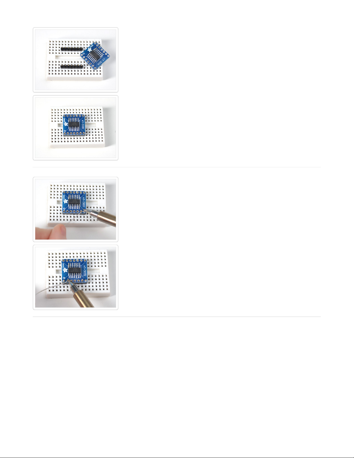
The hard part's done! Now we can solder
on regular 0.1" spaced male header. We
like the break-away kind so its easy to
get just the right amount. (You can get
some at the adafruit shop if you don't
have any!) (http://adafru.it/392)
Break two pieces the same length as the
pads on either side of the PCB and place
them into a breadboard, long pins down.
They should be parallel and the same
distance as the PCB pads so that you can
place the PCB on top with ease
Almost done, now all you have to do is
solder each header pin into the
corresponding hole to make a secure
connection
© Adafruit Industries Last Updated: 2013-03-31 09:30:21 PM EDT Page 8 of 8
 Loading...