

Page 1
CLUE Metal Detector in CircuitPython
Created by Kevin Walters
Last updated on 2021-02-08 06:48:17 PM EST
Page 2

2
4
4
4
4
5
5
7
7
8
8
8
10
10
11
12
13
13
14
15
16
16
17
17
17
19
21
22
22
24
24
26
26
26
26
26
28
28
29
29
29
41
41
42
43
43
44
45
47
47
52
52
52
52
Guide Contents
Guide Contents
Overview
Parts
CLUE version
Circuit Playground Bluefruit with TFT Gizmo version
Circuit Playground Bluefruit only version
Common
Design
Inductance and Permeability
Metal Detection
Beat Frequency From An Oscillator Pair
RLC Filters
Charging a Capacitor with RLD
Continuous Charge/Discharge with RLD
Two Coil Systems
CLUE Metal Detector
Microcontrollers vs Inductors
Microcontrollers vs Inductors
GPIO Protection
Larger Coil Currents
Circuit
Components
Coil Construction
Circuit Construction
CLUE board
Circuit Playground Bluefruit with TFT Gizmo
Circuit Playground Bluefruit board only
CircuitPython on CLUE
Set up CircuitPython Quick Start!
CircuitPython on Circuit Playground Bluefruit
Install or Update CircuitPython
CircuitPython
Libraries
Libraries for Metal Detector for CLUE
Libraries for Metal Detector for Circuit Playground Bluefruit with TFT Gizmo
Development Testing
Metal Detector
Example Video
Troubleshooting
Operation
Code
Code Discussion
Voltage from ADC Values
Using Global Variables in Python
Positional Arguments
Practical Issues with displayio Graphics
Filters with and without ulab Library
Magnetometer Baseline and Code Reviews
ADC Analysis
Voltage across Capacitor in the Metal Detector
Going Further
Ideas for Areas to Explore
Related Projects
Further Reading
© Adafruit Industries https://learn.adafruit.com/clue-metal-detector-circuitpython Page 2 of 54
Page 3

© Adafruit Industries https://learn.adafruit.com/clue-metal-detector-circuitpython Page 3 of 54
Page 4
Overview
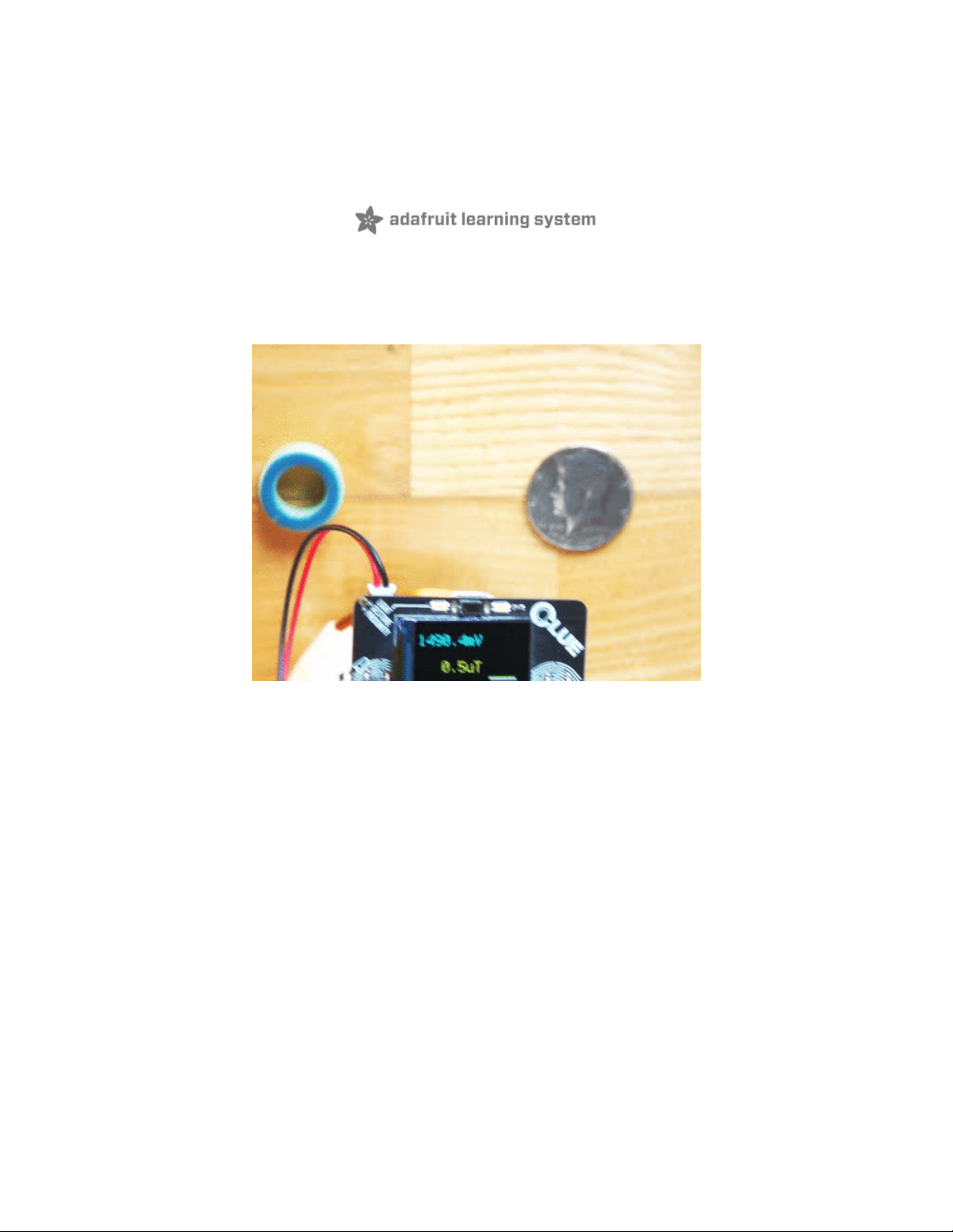
This project creates a metal detector using an Adafruit CLUE with a few common components and an
easy-to-make coil.
The program is written in CircuitPython for version 5.1.0 or later. The code also runs on the Circuit
Playground Bluefruit (CPB) with the TFT Gizmo screen. The program can be used without a screen on the
CPB in audio/light mode only.
Alligator clips to male jumpers can be used with or without the Adafruit Dragontail to connect the CLUE
and the coil to the breadboard. The pictures feature alternate products.
This project was inspired by an old Ray Marston book featuring a metal detector project and the
Detectorists (https://adafru.it/L7d) BBC TV series.
Parts
CLUE version
1 x Adafruit CLUE
Adafruit CLUE - nRF52840 Express with Bluetooth LE
1 x Adafruit DragonTail
Adafruit DragonTail for micro:bit - Fully Assembled (or use 3 Alligator Clip to Male Jumper Wires)
1 x 1k Resistor
Through-Hole Resistors - 1.0K ohm 5% 1/4W - Pack of 25 (1 needed)
Circuit Playground Bluefruit with TFT Gizmo version
Add to Cart
Out of
Stock
Out of
Stock
© Adafruit Industries https://learn.adafruit.com/clue-metal-detector-circuitpython Page 4 of 54
Page 5

1 x Circuit Playground Bluefruit (CPB)
Circuit Playground Bluefruit - Bluetooth Low Energy
1 x Circuit Playground TFT Gizmo (LCD Screen)
Circuit Playground TFT Gizmo - Bolt-on Display + Audio Amplifier
2 x STEMMA 3-Pin to Male Header Cable
STEMMA JST PH 3-Pin to Male Header Cable - 200mm
Circuit Playground Bluefruit only version
1 x Circuit Playground Bluefruit (CPB)
Circuit Playground Bluefruit - Bluetooth Low Energy
1 x 1k Resistor
Through-Hole Resistors - 1.0K ohm 5% 1/4W - Pack of 25 (1 needed)
Common
1 x USB 1m cable - A to Micro-B
USB cable - USB A to Micro-B - 3 foot long
1 x Half-size breadboard
Half-size breadboard
1 x Alligator Clip to Male Jumper Wires
Small Alligator Clip to Male Jumper Wire Bundle - 6 Pieces (2 needed for coil)
1 x Male/Male Jumper Wires
Premium Male/Male Jumper Wires - 40 x 3" (75mm)
1 x Signal Diode
1N4148 Signal Diode - 10 pack (1 needed)
1 x 0.1uF Capacitor
0.1uF ceramic capacitors - 10 pack (1 needed)
1 x 36ft (11m) Wire
Enameled Copper Magnet Wire – 11 meters / 0.1mm diameter (5-8m of most insulated wire will work fine)
Add to Cart
Add to Cart
Out of
Stock
Add to Cart
Out of
Stock
Add to Cart
Out of
Stock
Add to Cart
Add to Cart
Add to Cart
Add to Cart
Add to Cart
© Adafruit Industries https://learn.adafruit.com/clue-metal-detector-circuitpython Page 5 of 54
Page 6

1 x 3 x AAA Switched Battery Holder
3 x AAA Battery Holder with On/Off Switch and 2-Pin JST (if you want to be mobile!)
1 x AAA Batteries
Pack of 3
Add to Cart
Add to Cart
© Adafruit Industries https://learn.adafruit.com/clue-metal-detector-circuitpython Page 6 of 54
Page 7
Design
Inductance is a key part of many technologies in daily life, for example:
charging - electric toothbrushes, the latest smartphones and some wireless, in-ear headphones;
heating - induction cooking (https://adafru.it/L7e) with metal cookware;
communication - contactless smartcards using NFC (https://adafru.it/L7f), RFID (https://adafru.it/L7A)
tags and traditional tuning circuits for radios;
power supplies - transformers (https://adafru.it/L7B) reduce the mains AC voltage to a more practical
level;
metal detection - airport security, automatic car park exit gates, pipe/cable finders and hunting for
treasure.
Leon Theremin's The Thing (https://adafru.it/L7C) is an interesting, minimalist example of a resonant cavity
microphone, the equivalent of using an inductor for L (https://adafru.it/L7D)C (https://adafru.it/L7E) tuning,
an application of band-pass filtering (https://adafru.it/L7F).
Inductance and Permeability
A current flowing produces a magnetic field around it. Inductors are electrical components designed to
store energy in that magnetic field. These are typically coils and often wrapped around a core. The
magnetic field can be affected by:
the material it passes through, this property is referred to as magnetic
permeability; (https://adafru.it/L8a)
the presence of a conductor nearby changing the effective inductance of the coil from the induced
eddy currents (https://adafru.it/L8b) in that conductor creating their own magnetic field;
other magnetic fields.
These first two properties make the inductor useful for detecting conductive objects.
© Adafruit Industries https://learn.adafruit.com/clue-metal-detector-circuitpython Page 7 of 54
Page 8
MAKE Presents: The Inductor (https://adafru.it/L8c) is an excellent video introduction to inductors by Collin
Cunningham (https://adafru.it/L8d).
Metal Detection
The effect of nearby conductors on an inductor makes them a useful component for detecting metal. A
classic implementation of this in electronics uses heterodyning (https://adafru.it/L8e) where the beat
frequency from mixing an inductor-based search oscillator with a reference oscillator is output to
headphones.
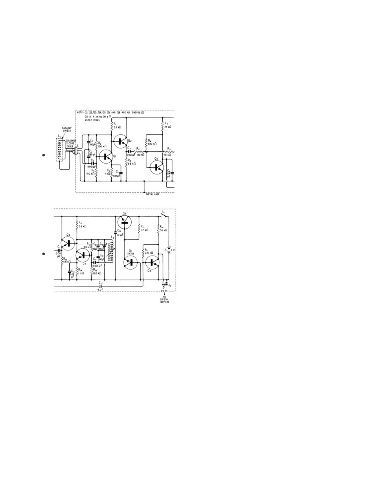
Beat Frequency From An Oscillator Pair
The schematic on the left from R.M. Marston's
20 Solid State
Projects For The Home (1969)
shows a transitor-based
detector with two colpitts oscillators (https://adafru.it/L8f). One
oscillator uses the search coil and the other a tuneable
reference coil which the users adjust to reduce the beat
frequency audio output to near 0Hz away from the target
material.
RLC Filters
Filters can easily be created with a resistor (R), an inductor (L) and a capacitor (C). There are a variety of
configurations of RLC filters (https://adafru.it/L8A) and many of them could be used to filter the square
wave output from a microcontroller which could then be sampled to check the attenuation of the filter
which would vary with the inductance.
An initial test of this approach with an Adafruit CLUE and a low-pass filter didn't yield promising results.
The plots below show theoretical plots for a band-stop (notch) filter made with a resistor and a parallel LC
circuit which might be worth exploring.
© Adafruit Industries https://learn.adafruit.com/clue-metal-detector-circuitpython Page 8 of 54
Page 9
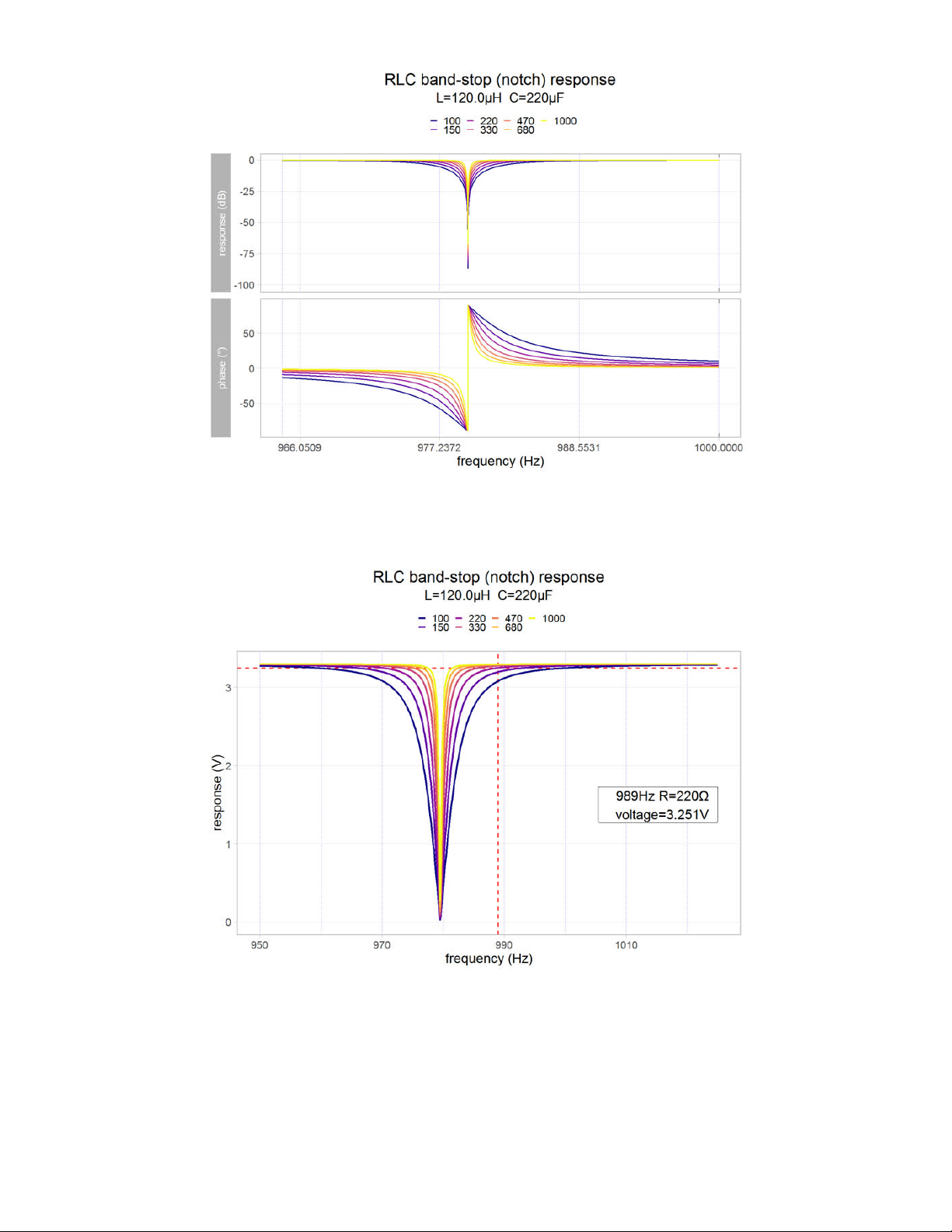
The lower resistor values might not be practical as they put a higher current demand on the GPIO port.
The annotated linear plot below is better for seeing how this attenuation could potentially be used to
detect small variations in inductance.
This would require sampling the 989Hz signal to determine the attenuation by the filter. A high
inductance is attractive here as it will lower the frequency making the determination of the attenuation
more accurate.
A frequency sweeping approach is an alternative for finding the frequency of the filter. This is likely to be
slower but it would be less ambiguous. A simple measurement approach at one frequency, say 2.741V,
© Adafruit Industries https://learn.adafruit.com/clue-metal-detector-circuitpython Page 9 of 54
Page 10
corresponds to
two
frequencies and therefore two different inductance values.
Charging a Capacitor with RLD
An Arduino-based project on Instructables (https://adafru.it/L8B) uses an RL circuit (https://adafru.it/L8C)
with the output rectified with a diode which then charges a capacitor. The steps in the measurement of
the inductance are:
1. A few pulses are output through the circuit to charge the capacitor. A higher inductance will result in
a higher final voltage across the capacitor.
2. An analogue input then measures the capacitor's voltage with over-sampling aiming to improve the
accuracy.
3. The analogue input is changed momentarily to
output mode
to empty (sink (https://adafru.it/L8D)) the
charge from the capacitor.
A C++ program (sketch) on the Arduino Uno offers precise timing. This is essential for this approach to
give accurate results for the inductance.
In CircuitPython, the pulseio library (https://adafru.it/L8E) can be used for creating PWM signals and pulse
trains with microsecond precision. In general, as an interpreted language with garbage collection, it does
not offer precise timing. The unpredictable delay between step 1 and step 2 is likely to affect the final
accuracy of the measurement causing sporadic, spurious indications.
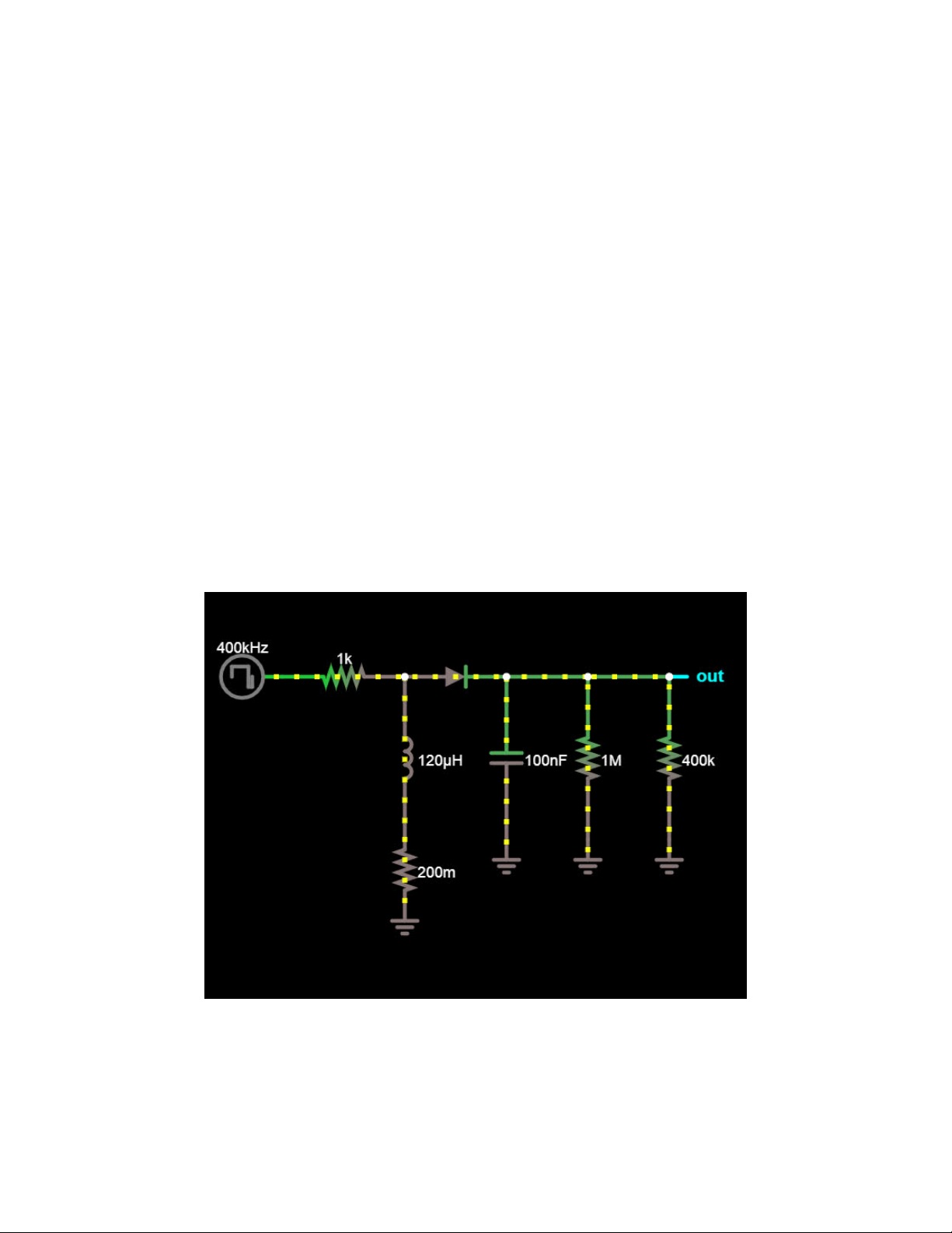
Continuous Charge/Discharge with RLD
The previous approach can be used in a continuous fashion where a constant series of pulses flow
through the RLD. A circuit diagram from the Falstad Circuit Simulator (https://adafru.it/L8F) is shown below.
This design could be considered as an RL filter with an envelope detector (https://adafru.it/L9a).
© Adafruit Industries https://learn.adafruit.com/clue-metal-detector-circuitpython Page 10 of 54
Page 11
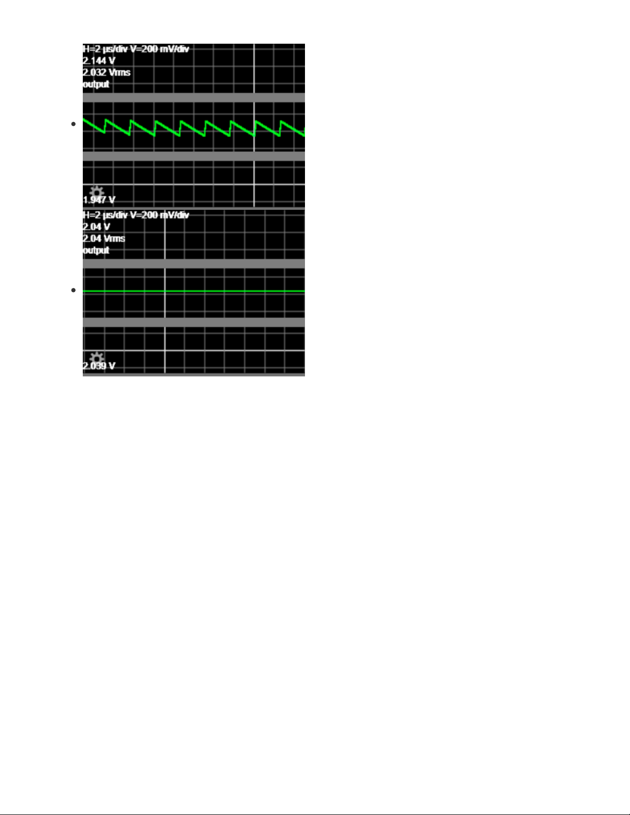
The value of the capacitor affects how quickly it discharges. A
tiny capacitance will cause a rapid discharge causing a ripple
which may reduce the accuracy or complicate the voltage
measurement. A large capacitor value will take time to charge
and discharge and this could make the sensing unresponsive.
A value of 0.1uF (which can be written as 100nF) was chosen
from experimental testing. For comparison, a simulation with
100pF (top left) shows a very undesirable 197mV of ripple
whereas 0.1uF only has ~1mV ripple.
A small amount of steady voltage drop around 1mV is actually useful here to ensure over-sampling is an
effective technique to improve the resolution. In the (unlikely) absence of noise or variation, a
theoretically
perfect
analogue to digital converter (ADC) (https://adafru.it/eYp) would output the same value repeatedly
for a constant voltage. The ADC Analysis (https://adafru.it/L9b) page takes a closer look at this.
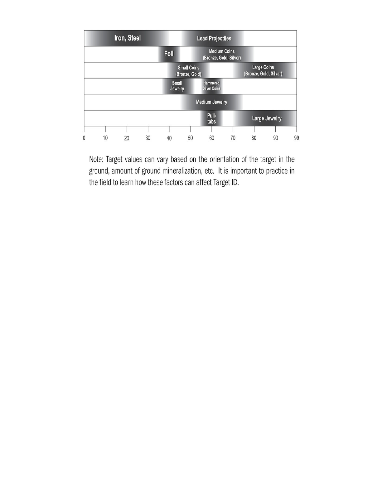
Two Coil Systems
Modern metal detectors using the induction balanced approach use two, often partially overlapping
search coils. One is used for transmitting and one for receiving. A relatively small overlap will create a
section with increased sensitivity. These detectors can discriminate to some extent between metals by
reporting on the phase difference (https://adafru.it/L9c) between the transmitted and received signal. This
is typically presented to the user as a numerical value with different ranges giving an approximate
identification. Garrett's chart for their AT Pro metal detector is shown below.
© Adafruit Industries https://learn.adafruit.com/clue-metal-detector-circuitpython Page 11 of 54
Page 12
CLUE Metal Detector
Some initial testing of the Continuous Charge/Discharge with RLD approach worked well so this was
selected for the project.
The CLUE has an onboard LIS3MDL, a triple-axis magnetometer. This is a useful addition for finding
magnets and magnetised items.
© Adafruit Industries https://learn.adafruit.com/clue-metal-detector-circuitpython Page 12 of 54
Page 13
Microcontrollers vs Inductors
Microcontrollers vs Inductors
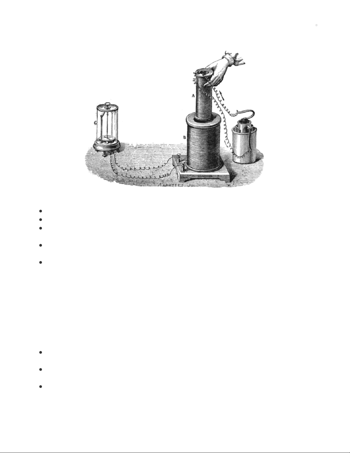
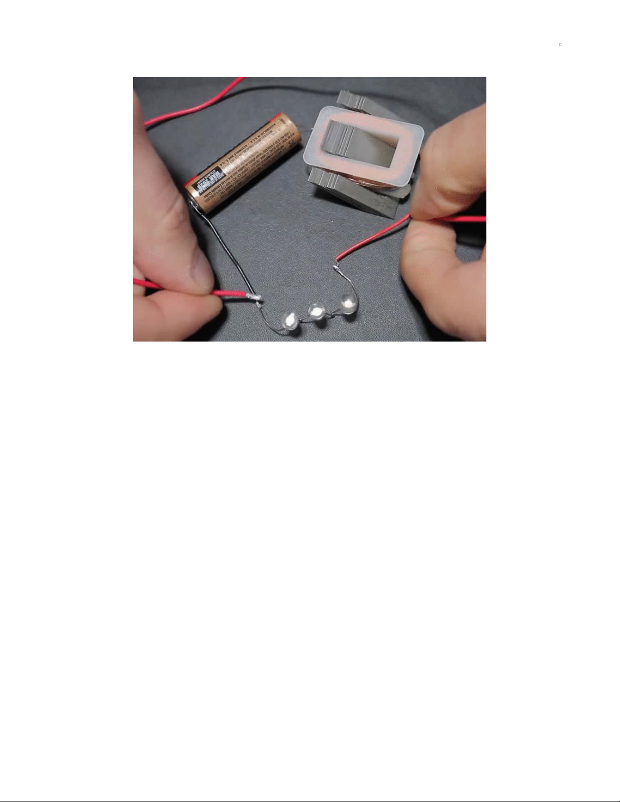
Inductors can generate high voltages which may exceed the desired levels in a circuit. The video above
shows a single-cell battery connected to an inductor (top right) in series with three white LEDs. The white
LEDs require over 9V to illuminate but a mere 1.5V battery is able to briefly illuminate them due to the
inductor's effect.
In this case the red wire is being used to briefly short across the non-conducting LEDs to allow current to
flow from the battery through the inductor. The inductor is storing energy in its magnetic field and this field
products the momentary higher voltage as the red wire is removed from the circuit. This demonstration of
voltage spikes suggests care is required when using inductors in circuits to keep voltage levels at normal
levels to avoid damaging sensitive components.
TDK (https://adafru.it/Lb1), a company founded on the invention of ferrite (https://adafru.it/Lb2), offers an
explanation of this below with a parallel version of the circuit lighting a 70V neon
lamp (https://adafru.it/Lb3) from a 4.5V battery. This is from TDK's The Wonders of Electromagnetism:
Power Inductors in Mobile Phones (https://adafru.it/Lb4).
© Adafruit Industries https://learn.adafruit.com/clue-metal-detector-circuitpython Page 13 of 54
Page 14
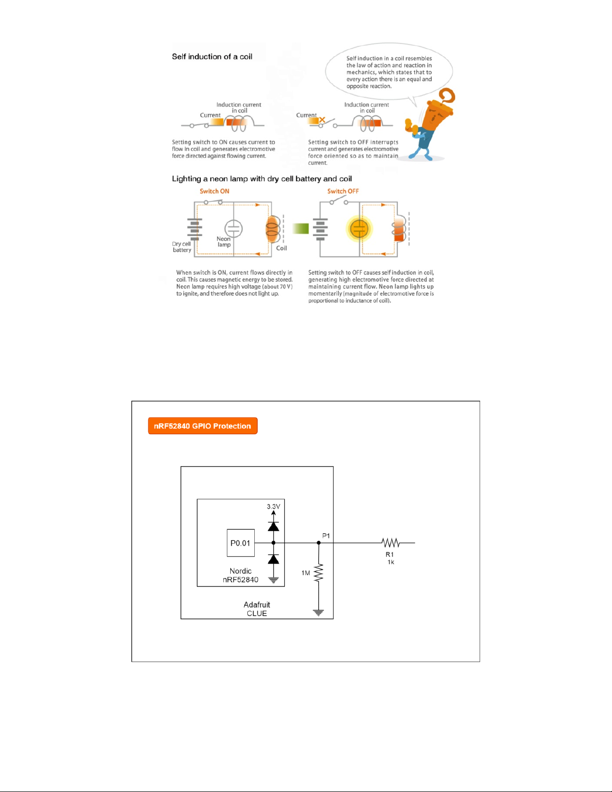
GPIO Protection
The general-purpose input/output (GPIO) (https://adafru.it/Lb5) pins on microcontrollers typically have
some limited protection built-in for adverse voltages often to deal with static electricity
(ESD (https://adafru.it/Lb6)). The CLUE board uses an nRF52 series chip and this has two internal
diodes (https://adafru.it/Lb7) on each GPIO pin. The partial schematic below shows an example of how
these these two diodes are used for one pin.
The schematic shows the CLUE board's 1 Megaohm resistor. There's one resistor per large pad used for
the capacitive touch (https://adafru.it/Lb8) implementation. The schematic also shows an
external
resistor.
This is another precaution that's typically used to limit output current but it will also reduce any current
© Adafruit Industries https://learn.adafruit.com/clue-metal-detector-circuitpython Page 14 of 54
Page 15
flowing through these
very small
, protective diodes in the microcontroller.
The metal detector circuit on the next page uses a resistor
primarily to limit the current from the P1
output
but it will also
reduce any adverse currents from under or over voltages
caused by the inductor.
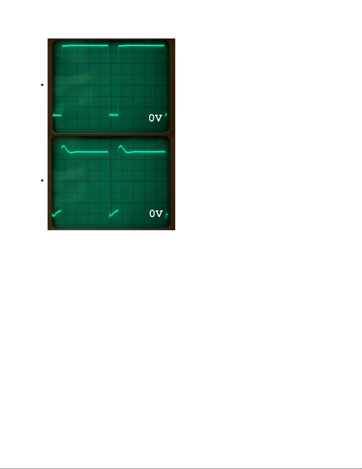
The square wave (3.3V pk-pk (https://adafru.it/oDb), 84% duty
cycle (https://adafru.it/Lb9)) can be seen with and without the
inductor in the circuit here. The inductor does cause a small
negative
voltage which briefly "peaks" at -0.6V on the P1
pin/pad. The magnitude and brevity of this spike and the
current protection from the external 1k resistor mean the
microcontroller is not at risk.
Larger Coil Currents
If more current was being used through the coil then an external protection diode capable of handling this
higher current would be a wise precaution. The CLUE's nRF52840 can only supply low currents, higher
currents would need a separate power supply and switching with a transistor. This could aid isolation of
the GPIO from the maleffects of the voltage spikes.
Diodes are commonly found across motors (https://adafru.it/CkQ), relays and solonoids protecting against
back EMF (https://adafru.it/Lba) and are sometimes referred to as "flyback" diodes (https://adafru.it/Lbb).
© Adafruit Industries https://learn.adafruit.com/clue-metal-detector-circuitpython Page 15 of 54
Page 16

Circuit
This page describes how the components are used on the breadboard to make the circuit for the metal
detector. It also describes how to make and connect the coil.
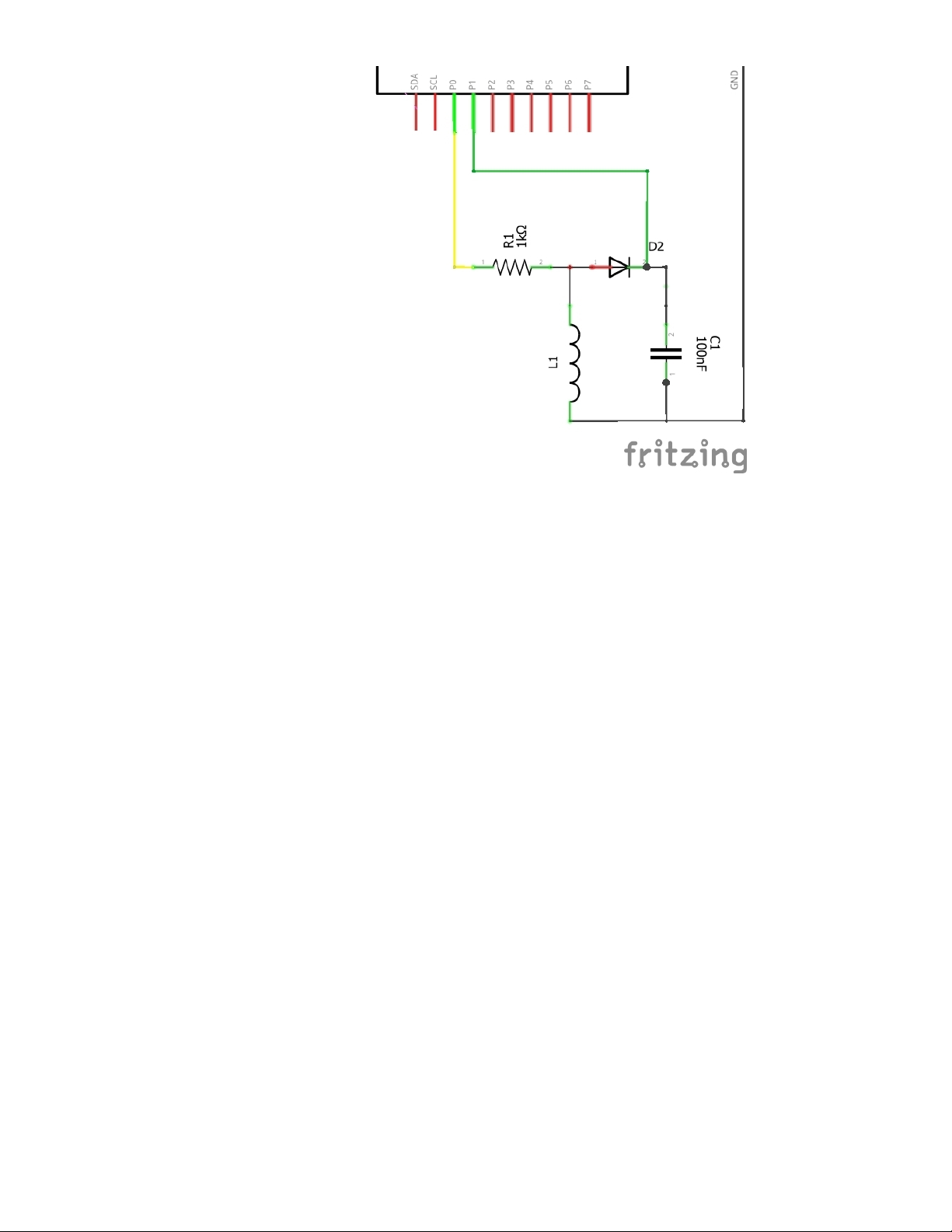
Components
The components in the circuit are:
R1 - 1k resistor.
D2 - 1N4148 signal diode (there is no D1).
C1 - 0.1uF (100nF) ceramic capacitor. These small capacitors are often labelled "104".
L1 - home-made coil.
The prototype was made with a 1N4004 rectifier diode and also tested with a germanium diode from a
crystal radio set, both worked well and could be used as alternatives to the 1N4148 diode.
© Adafruit Industries https://learn.adafruit.com/clue-metal-detector-circuitpython Page 16 of 54
Page 17
Coil Construction
A coil with about 4-8m (13-26ft) is a good starting point to avoid using too much wire. Insulated wire will
work but "enamelled" copper wire (https://adafru.it/Lbc) allows a more compact coil. The enamel is a
misnomer, the coating will be something like polyurethane varnish. This insulation must be
scraped
or
burnt off
with a soldering iron at the ends to expose the copper to connect it to the circuit.
The coil shown at the top of the page is enamelled 0.56mm wire wrapped around an 84mm tube (3.3in). It
has 12 coils then 9 more coils over those then 7 coil more coils over those totalling 28. Placing the coils
close to the edge improves the effective search range but care needs to be taken to ensure the coil does
not fall off! A tiny ridge has been made on end of the tube with masking tape to reduce that risk.
The coil either needs to be very tight or held in place as movement of the wire in the coil will subtly affect
the inductance and parasitic capacitance (https://adafru.it/Lbd) of the coil.
A prototype coil was also made (not shown) with 20 turns around a core of a roll of masking tape with
diameter 116mm (4.6in). This worked well too.
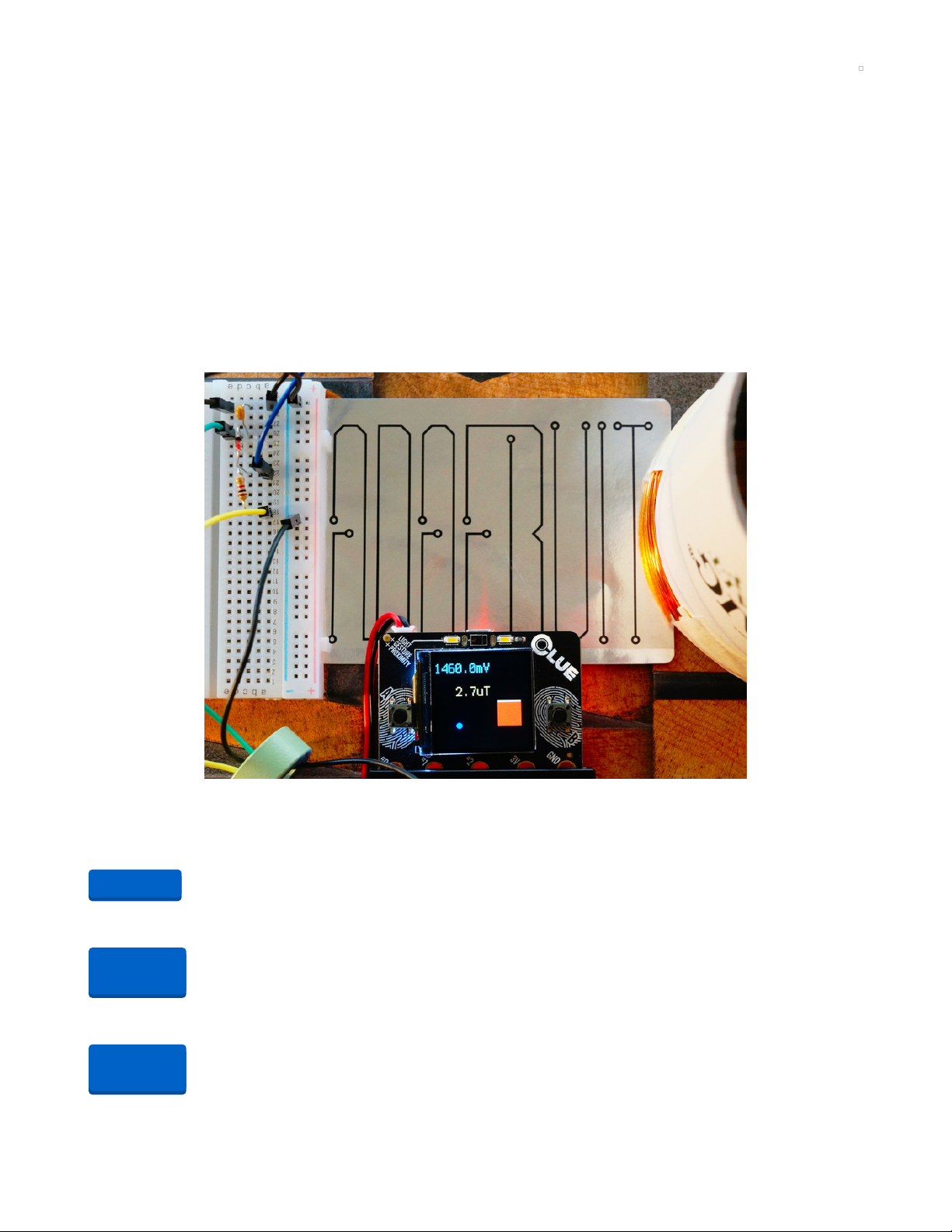
Circuit Construction
The diagrams and pictures below show how the circuit can be implemented on a breadboard for the three
different configurations.
CLUE board
© Adafruit Industries https://learn.adafruit.com/clue-metal-detector-circuitpython Page 17 of 54
Page 18

The coil needs to be connected to the breadboard. The options are:
Thick solid core wire may be directly inserted into the breadboard. Tinning the end with solder will
increase the diameter of a wire and tame multi-strand wire.
A connector cable with male pins to alligator (crocodile) clips or hooks (shown below). These will be
needed for the Adafruit enamelled wire.
The CLUE board can be connected using the Dragontail or alligator clips.
#0 (P0) yellow wire - this is the square wave output.
#1 (P1) green wire - this is an analogue input measuring the voltage across the capacitor.
© Adafruit Industries https://learn.adafruit.com/clue-metal-detector-circuitpython Page 18 of 54
Page 19

GND black wire - this is only required if not using the Dragontail. The Dragontail directly connects to
the power rails on
one
side of the breadboard.
It's best to insert or remove a CLUE board from an edge connector with the power off to prevent
inadvertent, transient short circuits.
Everything can be seen connected together in the picture below. A Kitronik Edge Connector Breakout
Board for BBC micro:bit (https://adafru.it/Lbe) (over the top half of the breadboard) and Pimoroni IC hooks
with pigtails (https://adafru.it/Lbf) (to connect the coil) have been used for this implementation.
The circuit can only be tested once the CLUE has the CircuitPython program on it. This is described on
the next page.
If alligator clips are used they need to be carefully placed in the centre of the pad and protected
from accidental nudges which could cause the alligator clip to connect across the small pads either
side of #0, #1 or GND.
Circuit Playground Bluefruit with TFT Gizmo
The CPB board pads are not really accessible when the TFT Gizmo is attached and most of them are used
for the Gizmo. The Gizmo has 3-pin STEMMA connectors for accessing A1 and A2. A pair of STEMMA 3-
Pin to male cables (https://adafru.it/CVg) are required to connect this to the breadboard.
© Adafruit Industries https://learn.adafruit.com/clue-metal-detector-circuitpython Page 19 of 54
Page 20

The connections are:
A1 STEMMA (square wave output):
red - breadboard red (+) rail (not used).
white (yellow sleeves) - breadboard b22.
black - breadboard black (-) rail.
A2 STEMMA (analogue input):
red - breadboard red (+) rail (not used).
white (green sleeves) - breadboard e26.
black - breadboard black (-) rail.
© Adafruit Industries https://learn.adafruit.com/clue-metal-detector-circuitpython Page 20 of 54
Page 21

The TFT Gizmo has its own 1k resistors on the A1/A2 GPIO making the resistor on the breadboard
superfluous.
The red power lines are not used but plugging the pins into the breadboard prevents them from
accidentally contacting other components or shorting to ground.
The red power lines from the STEMMA connector on the TFT Gizmo are at VOUT level, i.e. 5V for
USB power or the battery voltage.
Circuit Playground Bluefruit board only
The program still runs without a screen on a CPB board in audio/light mode.
The connections are:
A1 (square wave output) - yellow wire - breadboard a18.
A2 (analogue input) - green wire - breadboard e26.
GND - black wire - breadboard black (-) rail.
© Adafruit Industries https://learn.adafruit.com/clue-metal-detector-circuitpython Page 21 of 54
Page 22

CircuitPython on CLUE
CircuitPython (https://adafru.it/tB7) is a derivative of MicroPython (https://adafru.it/BeZ) designed to
simplify experimentation and education on low-cost microcontrollers. It makes it easier than ever to get
prototyping by requiring no upfront desktop software downloads. Simply copy and edit files on the
CIRCUITPY flash drive to iterate.
The following instructions will show you how to install CircuitPython. If you've already installed
CircuitPython but are looking to update it or reinstall it, the same steps work for that as well!
Set up CircuitPython Quick Start!
Follow this quick step-by-step for super-fast Python power :)
https://adafru.it/IHF
Click the link above to download the latest version of
CircuitPython for the CLUE.
Download and save it to your desktop (or wherever is handy).
Plug your CLUE into your computer using a known-good USB
cable.
A lot of people end up using charge-only USB cables and it
is very frustrating! So make sure you have a USB cable you
know is good for data sync.
Double-click the Reset button on the top (magenta arrow) on
your board, and you will see the NeoPixel RGB LED (green
arrow) turn green. If it turns red, check the USB cable, try
another USB port, etc. Note: The little red LED next to the
USB connector will pulse red. That's ok!
If double-clicking doesn't work the first time, try again.
Sometimes it can take a few tries to get the rhythm right!
https://adafru.it/IHF
© Adafruit Industries https://learn.adafruit.com/clue-metal-detector-circuitpython Page 22 of 54
Page 23

You will see a new disk drive appear called CLUEBOOT.
Drag the adafruit-circuitpython-clue-etc.uf2 file to
CLUEBOOT.
The LED will flash. Then, the CLUEBOOT drive will disappear
and a new disk drive called CIRCUITPY will appear.
If this is the first time you're installing CircuitPython or you're
doing a completely fresh install after erasing the filesystem,
you will have two files - boot_out.txt, and code.py, and one
folder - lib on your CIRCUITPY drive.
If CircuitPython was already installed, the files present before
reloading CircuitPython should still be present on your
CIRCUITPY drive. Loading CircuitPython will not create new
files if there was already a CircuitPython filesystem present.
That's it, you're done! :)
© Adafruit Industries https://learn.adafruit.com/clue-metal-detector-circuitpython Page 23 of 54
Page 24

CircuitPython on Circuit Playground Bluefruit
Install or Update CircuitPython
Follow this quick step-by-step to install or update CircuitPython on your Circuit Playground Bluefruit.
https://adafru.it/FNK
Click the link above and download the latest UF2 file
Download and save it to your Desktop (or wherever is handy)
Plug your Circuit Playground Bluefruit into your computer
using a known-good data-capable USB cable.
A lot of people end up using charge-only USB cables and it
is very frustrating! So make sure you have a USB cable you
know is good for data sync.
Double-click the small Reset button in the middle of the CPB
(indicated by the red arrow in the image). The ten NeoPixel
LEDs will all turn red, and then will all turn green. If they turn
all red and stay red, check the USB cable, try another USB
port, etc. The little red LED next to the USB connector will
pulse red - this is ok!
If double-clicking doesn't work the first time, try again.
Sometimes it can take a few tries to get the rhythm right!
(If double-clicking doesn't do it, try a single-click!)
https://adafru.it/FNK
© Adafruit Industries https://learn.adafruit.com/clue-metal-detector-circuitpython Page 24 of 54
Page 25

You will see a new disk drive appear called CPLAYBTBOOT.
Drag the adafruit_circuitpython_etc.uf2 file to
CPLAYBTBOOT.
The LEDs will turn red. Then, the CPLAYBTBOOT drive will
disappear and a new disk drive called CIRCUITPY will
appear.
That's it, you're done! :)
© Adafruit Industries https://learn.adafruit.com/clue-metal-detector-circuitpython Page 25 of 54
Page 26

CircuitPython
Libraries
Once you've gotten CircuitPython onto your CLUE or Circuit Playground Bluefruit (CPB) board, it's time to
add some libraries. You can follow this guide page (https://adafru.it/GdM) for the basics of downloading
and transferring libraries to the board.
https://adafru.it/ENC
Libraries for Metal Detector for CLUE
From the library bundle you downloaded in that guide page, transfer the following libraries onto the CLUE
board's /lib directory:
adafruit_apds9960
adafruit_bus_device
adafruit_display_notification
adafruit_display_text
adafruit_register
adafruit_display_shapes
adafruit_bmp280.mpy
adafruit_clue.mpy
adafruit_lis3mdl.mpy
adafruit_lsm6ds.mpy
adafruit_sht31d.mpy
adafruit_slideshow.mpy
neopixel.mpy
There are many libraries with similar names, take care on the selection.
Libraries for Metal Detector for Circuit Playground Bluefruit with TFT Gizmo
From the library bundle you downloaded in that guide page, transfer the following libraries onto the CPB
board's /lib directory:
adafruit_gizmo
adafruit_circuitplayground
adafruit_display_shapes
adafruit_bus_device
adafruit_display_notification
adafruit_display_text
adafruit_register
adafruit_lis3dh.mpy
adafruit_thermistor.mpy
adafruit_st7789.mpy
neopixel.mpy
Development Testing
During development, the application was tested on a CLUE using CircuitPython 5.2.0 with libraries from
the adafruit-circuitpython-bundle-5.x-mpy-20200501.zip bundle. It should work on subsequent versions,
https://adafru.it/ENC
© Adafruit Industries https://learn.adafruit.com/clue-metal-detector-circuitpython Page 26 of 54
Page 27

the latest version is recommended for the CLUE (https://adafru.it/IHF).
A small amount of testing was also performed on a Circuit Playground Bluefruit (https://adafru.it/FNK) with
a TFT Gizmo.
© Adafruit Industries https://learn.adafruit.com/clue-metal-detector-circuitpython Page 27 of 54
Page 28

Metal Detector
Download the CircuitPython file below renaming the clue-metal-detector.py to code.py by clicking on the
links and then using Save as... / Save link as... in the browser. The files are hosted on Adafruit's GitHub
repo for this project (https://adafru.it/L9d).
https://adafru.it/L9e
Plug your CLUE/CPB board into your computer via a known-good USB data cable. A flash drive named
CIRCUITPY should appear in your file explorer/finder program. Copy the file t o the CIRCUITPY drive
ensuring the clue-metal-detector.py is renamed to code.py. (https://adafru.it/EL3)
Example Video
The video shows the CLUE version powered by a lithium polymer battery similar to the Adafruit 1200mAh
Lithium Ion Polymer battery (https://adafru.it/dyW). Note: the CLUE and the CPB do not have an integrated
charger.
In the video, when no object is being sensed, the voltage shown on the screen is around 1474mV and
magnitude of the magnetic flux density difference is 0uT. The five hidden objects, in order, show the
following voltages:
Through a large hardback book
a large metallic sticker, 1467mV.
Through a magazine
another Adafruit CLUE board, 1463mV;
a ferrite core from an inductor, 1477mV (note the value has
increased
);
a neodymium magnet, 1474mV and 28uT;
a large silver coin 1469mV.
https://adafru.it/L9e
© Adafruit Industries https://learn.adafruit.com/clue-metal-detector-circuitpython Page 28 of 54
Page 29

The voltage will vary based on the inductance of the coil created for the metal detector. It will be about
300mV less if a rectifier diode like a 1N1004 is used. The voltage is about 200mV less on the Circuit
Playground Bluefruit with TFT Gizmo for the same coil.
Troubleshooting
If the metal detector is not working, here's some tips based on observing the voltage.
Around 2950mV: the coil is not connected or the connection is hampered by insulation left on the
enamelled wire.
Around 0mV: diode may be the wrong way around or something is not connected properly.
A few tens of mV: the yellow connection is probably from a high (3.3V) pin.
Voltage jumps around: probably a loose connection and/or ground is not attached. Wiggle and re-
insert connections to find problematic one. Using alternate holes/rows on the breadboard can help
sometimes.
Operation
The mV value across the capacitor is shown on screen. This value represents the inductance value. The
detection of metal is based on a positive or negative
change
from the baseline value when no object is
being sensed. A difference is indicated by a beeping sound, a bar graph with green for positive and red
for negative and flashing of the NeoPixel(s) with a matching colour. The baseline value is assigned when
the code first starts. It will also follow any changes after about ten seconds.
The uT reading (CLUE board only) is the magnitude of the difference between the magnetometer's z
component only and the first value measured at start-up. This value is also shown as a filled blue circle, a
slightly different beeping sound and flashing of the NeoPixel(s) in blue alternating with any mV related
colour.
The use of the z component only is a crude approach to make the detector ignore the Earth's magnetic
field. This allows the detector to be rotated as this changes the x and y values but not the z value. Tilting
the device, as seen in the video when the metal detector is at the top of the screen, will unfortunately
increase the value slightly.
The right button can be used to immediately reset the baseline for the voltage and the magnetic flux
density. The left button toggles the audio, NeoPixel(s), screen and Mu output on and off depending on the
duration of the button press.
Magnets at close proximity can permanently magnetise components on the CLUE board affecting
the magnetometer! Keep them at least 10cm (4in) away from the CLUE.
Code
A code discussion (https://adafru.it/L9f) follows the code.
# clue-metal-detector v1.6
# A simple metal detector using a minimum number of external components
# Tested with an Adafruit CLUE (Alpha) and CircuitPython 5.2.0
# Tested with an Adafruit Circuit Playground Bluefruit with TFT Gizmo
# and CircuitPython 5.2.0
© Adafruit Industries https://learn.adafruit.com/clue-metal-detector-circuitpython Page 29 of 54
Page 30

# CLUE: Pad P0 is an output and pad P1 is an input
# CPB: Pad/STEMMA A1 is an output and Pad/STEMMA A2 is an input
# copy this file to CLUE/CPB board as code.py
# MIT License
# Copyright (c) 2020 Kevin J. Walters
# Permission is hereby granted, free of charge, to any person obtaining a copy
# of this software and associated documentation files (the "Software"), to deal
# in the Software without restriction, including without limitation the rights
# to use, copy, modify, merge, publish, distribute, sublicense, and/or sell
# copies of the Software, and to permit persons to whom the Software is
# furnished to do so, subject to the following conditions:
# The above copyright notice and this permission notice shall be included in all
# copies or substantial portions of the Software.
# THE SOFTWARE IS PROVIDED "AS IS", WITHOUT WARRANTY OF ANY KIND, EXPRESS OR
# IMPLIED, INCLUDING BUT NOT LIMITED TO THE WARRANTIES OF MERCHANTABILITY,
# FITNESS FOR A PARTICULAR PURPOSE AND NONINFRINGEMENT. IN NO EVENT SHALL THE
# AUTHORS OR COPYRIGHT HOLDERS BE LIABLE FOR ANY CLAIM, DAMAGES OR OTHER
# LIABILITY, WHETHER IN AN ACTION OF CONTRACT, TORT OR OTHERWISE, ARISING FROM,
# OUT OF OR IN CONNECTION WITH THE SOFTWARE OR THE USE OR OTHER DEALINGS IN THE
# SOFTWARE.
# pylint: disable=global-statement
import time
import math
import array
import os
import gc
import board
import pulseio
import analogio
import ulab
from displayio import Group
import terminalio
# These imports works on CLUE, CPB (and CPX on 5.x)
from audiocore import RawSample
try:
from audioio import AudioOut
except ImportError:
from audiopwmio import PWMAudioOut as AudioOut
# displayio graphical objects
from adafruit_display_text.label import Label
from adafruit_display_shapes.rect import Rect
from adafruit_display_shapes.circle import Circle
# Assuming CLUE if it's not a Circuit Playround (Bluefruit)
clue_less = "Circuit Playground" in os.uname().machine
if clue_less:
# CPB with TFT Gizmo (240x240)
from adafruit_circuitplayground import cp
from adafruit_gizmo import tft_gizmo
© Adafruit Industries https://learn.adafruit.com/clue-metal-detector-circuitpython Page 30 of 54
Page 31

# Outputs
display = tft_gizmo.TFT_Gizmo()
audio_out = AudioOut(board.SPEAKER)
min_audio_frequency = 100
max_audio_frequency = 4000
pixels = cp.pixels
board_pin_output = board.A1
# Enable the onboard amplifier for speaker
cp._speaker_enable.value = True # pylint: disable=protected-access
# Inputs
board_pin_input = board.A2
magnetometer = None # This indicates device is not present
button_left = lambda: cp.button_b
button_right = lambda: cp.button_a
else:
# CLUE with builtin screen (240x240)
from adafruit_clue import clue
# Outputs
display = board.DISPLAY
audio_out = AudioOut(board.SPEAKER)
min_audio_frequency = 100
max_audio_frequency = 5000
pixels = clue.pixel
board_pin_output = board.P0
# Inputs (buttons reversed as it is used upside-down with Gizmo)
board_pin_input = board.P1
magnetometer = lambda: clue.magnetic
button_left = lambda: clue.button_a
button_right = lambda: clue.button_b
# Globals variables used r/w in functions
last_frequency = 0
last_negbar_len = None
last_posbar_len = None
last_mag_radius = None
text_overlay_gob = None
voltage_barneg_dob = None
voltage_sep_dob = None
voltage_barpos_dob = None
magnet_circ_dob = None
# Globals
debug = 1
screen_height = display.height
screen_width = display.width
samples = []
# Other globals
quantize_tones = True
audio_on = True
screen_on = True
mu_output = False
neopixel_on = True
# Used to alternate/flash the NeoPixel
neopixel_alternate = True
© Adafruit Industries https://learn.adafruit.com/clue-metal-detector-circuitpython Page 31 of 54
Page 32

# Some constants used in start_beep()
BASE_NOTE = 261.6256 # C4 (middle C)
QUANTIZE = 4 # determines the "scale"
POSTLOG_FACTOR = QUANTIZE / math.log(2)
AUDIO_MIDPOINT = 32768
# There's room for 80 pixels but 60 draws a bit quicker
VOLTAGE_BAR_WIDTH = 60
VOLTAGE_BAR_HEIGHT = 118
VOLTAGE_BAR_SEP_HEIGHT = 4
MAG_MAX_RADIUS = 50
VOLTAGE_FMT = "{:6.1f}"
MAG_FMT = "{:6.1f}"
INFO_FG_COLOR = 0x000080
INFO_BG_COLOR = 0xc0c000
BLACK_TUPLE = (0, 0, 0)
RED = 0xff0000
GREEN75 = 0x00c000
BLUE = 0x0000ff
WHITE75 = 0xc0c0c0
FONT_WIDTH, FONT_HEIGHT = terminalio.FONT.get_bounding_box()
# Thresholds below which audio is silent and NeoPixels are dark
threshold_voltage = 0.002
threshold_mag = 2.5
def d_print(level, *args, **kwargs):
"""A simple conditional print for debugging based on global debug level."""
if not isinstance(level, int):
print(level, *args, **kwargs)
elif debug >= level:
print(*args, **kwargs)
# Adapted and borrowed from clue-plotter v1.14
def wait_release(text_func, button_func, menu):
"""Calls button_func repeatedly waiting for it to return a false value
and goes through menu list as time passes.
The menu is a list of menu entries where each entry is a
two element list of time passed in seconds and text to display
for that period. Text is displayed by calling text_func(text).
The entries must be in ascending time order."""
start_t_ns = time.monotonic_ns()
menu_option = None
selected = False
for menu_option, menu_entry in enumerate(menu):
menu_time_ns = start_t_ns + int(menu_entry[0] * 1e9)
menu_text = menu_entry[1]
if menu_text:
text_func(menu_text)
while time.monotonic_ns() < menu_time_ns:
if not button_func():
selected = True
© Adafruit Industries https://learn.adafruit.com/clue-metal-detector-circuitpython Page 32 of 54
Page 33

break
if menu_text:
text_func("")
if selected:
break
return (menu_option, (time.monotonic_ns() - start_t_ns) * 1e-9)
def popup_text(text_func, text, duration=1.0):
"""Place some text on the screen using info property of Plotter object
for duration seconds."""
text_func(text)
time.sleep(duration)
text_func(None)
def show_text(text):
"""Place text on the screen. Empty string or None clears it."""
global screen_group, text_overlay_gob
if text:
font_scale = 3
line_spacing = 1.25
text_lines = text.split("\n")
max_word_chars = max([len(word) for word in text_lines])
# If too large reduce the scale to 2 and hope!
if (max_word_chars * font_scale * FONT_WIDTH > screen_width
or (len(text_lines) * font_scale
* FONT_HEIGHT * line_spacing) > screen_height):
font_scale -= 1
text_overlay_gob = Label(terminalio.FONT,
text=text,
scale=font_scale,
background_color=INFO_FG_COLOR,
color=INFO_BG_COLOR)
# Centre the (left justified) text
text_overlay_gob.x = (screen_width
- font_scale * FONT_WIDTH * max_word_chars) // 2
text_overlay_gob.y = screen_height // 2
screen_group.append(text_overlay_gob)
else:
if text_overlay_gob is not None:
screen_group.remove(text_overlay_gob)
text_overlay_gob = None
def voltage_bar_set(volt_diff):
"""Draw a bar based on positive or negative values.
Width of 60 is performance compromise as more pixels take longer."""
global voltage_sep_dob, voltage_barpos_dob, voltage_barneg_dob
global last_negbar_len, last_posbar_len
if voltage_sep_dob is None:
voltage_sep_dob = Rect(160, VOLTAGE_BAR_HEIGHT,
VOLTAGE_BAR_WIDTH, VOLTAGE_BAR_SEP_HEIGHT,
fill=WHITE75)
screen_group.append(voltage_sep_dob)
if volt_diff < 0:
negbar_len = max(min(-round(volt_diff * 5e3),
© Adafruit Industries https://learn.adafruit.com/clue-metal-detector-circuitpython Page 33 of 54
Page 34

VOLTAGE_BAR_HEIGHT), 1)
posbar_len = 1
else:
negbar_len = 1
posbar_len = max(min(round(volt_diff * 5e3),
VOLTAGE_BAR_HEIGHT), 1)
if posbar_len == last_posbar_len and negbar_len == last_negbar_len:
return
if voltage_barpos_dob is not None:
screen_group.remove(voltage_barpos_dob)
if posbar_len > 0:
voltage_barpos_dob = Rect(160, VOLTAGE_BAR_HEIGHT - posbar_len,
VOLTAGE_BAR_WIDTH, posbar_len,
fill=GREEN75)
screen_group.append(voltage_barpos_dob)
last_posbar_len = posbar_len
if voltage_barneg_dob is not None:
screen_group.remove(voltage_barneg_dob)
if negbar_len > 0:
voltage_barneg_dob = Rect(160,
VOLTAGE_BAR_HEIGHT + VOLTAGE_BAR_SEP_HEIGHT,
VOLTAGE_BAR_WIDTH, negbar_len,
fill=RED)
screen_group.append(voltage_barneg_dob)
last_negbar_len = negbar_len
def magnet_circ_set(mag_ut):
"""Display a filled circle to represent the magnetic value mag_ut in microteslas."""
global magnet_circ_dob
global last_mag_radius
# map microteslas to a radius with minimum of 1 and
# maximum of MAG_MAX_RADIUS
radius = min(max(round(math.sqrt(mag_ut) * 4), 1), MAG_MAX_RADIUS)
if radius == last_mag_radius:
return
if magnet_circ_dob is not None:
screen_group.remove(magnet_circ_dob)
magnet_circ_dob = Circle(60, 180, radius, fill=BLUE)
screen_group.append(magnet_circ_dob)
def manual_screen_refresh(disp):
"""Refresh the screen as immediately as is currently possibly with refresh method."""
refreshed = False
while True:
try:
# 1000fps is fastest library allows - this high value
# minimises any delays this refresh() method introduces
refreshed = disp.refresh(minimum_frames_per_second=0,
target_frames_per_second=1000)
except RuntimeError:
pass
if refreshed:
break
© Adafruit Industries https://learn.adafruit.com/clue-metal-detector-circuitpython Page 34 of 54
Page 35

def neopixel_set(pix, d_volt, mag_ut):
"""Set all the NeoPixels to an alternating colour
based on voltage difference and
magnitude of magnetic flux density difference."""
global neopixel_alternate
np_r, np_g, np_b = BLACK_TUPLE
if neopixel_alternate:
# RGB values are 8bit, hence the cap of 255 using min()
if abs(d_volt) > threshold_voltage:
if d_volt < 0.0:
np_r = min(round(-d_volt * 8e3), 255)
else:
np_g = min(round(d_volt * 8e3), 255)
else:
if mag_ut > threshold_mag:
np_b = min(round(mag_ut * 6), 255)
pix.fill((np_r, np_g, np_b)) # Note: double brackets to pass tuple
neopixel_alternate = not neopixel_alternate
def start_beep(freq, wave, wave_idx):
"""Start playing a continous beep based on freq and waveform specified by wave_idx.
A frequency of 0 will stop the note playing.
This quantizes the notes into a scale to make beeping sound more pleasant.
This modifies the sample_rate property of the RawSample objects.
"""
global last_frequency
if freq == 0:
if last_frequency != 0:
audio_out.stop()
last_frequency = 0
return
if quantize_tones:
note_freq = BASE_NOTE * 2**((round(math.log(freq / BASE_NOTE)
* POSTLOG_FACTOR)) / QUANTIZE)
d_print(3, "Quantize", freq, note_freq)
else:
note_freq = freq
(waveform, wave_samples_n) = wave[wave_idx]
new_freq = round(note_freq * wave_samples_n)
# Only set the new frequency if it's not the same as last one
if new_freq != last_frequency:
waveform.sample_rate = new_freq
audio_out.play(waveform, loop=True)
last_frequency = new_freq
def make_sample_list(levels=10,
volume=32767,
range_l=24,
start_l=8):
"""Make a list of tuples of (RawSample, sample_length)
with a sine wave of varying resolution from high to low.
The lower resolutions sound crunchier and louder on the CLUE."""
# Make a range of sample lengths, default is between 32 and 8
sample_lens = [int((x*(range_l + .99)/(levels - 1)) + start_l)
for x in range(0, levels)]
sample_lens.reverse()
© Adafruit Industries https://learn.adafruit.com/clue-metal-detector-circuitpython Page 35 of 54
Page 36

wavefs = []
for s_len in sample_lens:
raw_samples = array.array("H",
[round(volume * math.sin(2 * math.pi
* (idx / s_len)))
+ AUDIO_MIDPOINT
for idx in range(s_len)])
sound_samples = RawSample(raw_samples)
wavefs.append((sound_samples, s_len))
return wavefs
waveforms = make_sample_list()
# For testing the waveforms
if debug >= 4:
for idx in range(len(waveforms)):
start_beep(440, waveforms, idx)
time.sleep(0.1)
start_beep(0, waveforms, 0) # This silences it
# See https://forums.adafruit.com/viewtopic.php?f=60&t=164758 for
# a comparison and performance analysis of alternate techniques for this
def sample_sum(pin, num):
"""Sample the analogue value from pin num times and return the sum
of the values."""
global samples # Not strictly needed - indicative of r/w use
samples[:] = [pin.value for _ in range(num)]
return sum(samples)
# Initialise detector display
# The units are created as separate text objects as they are static
# and this reduces the amount of redrawing for the dynamic numbers
FONT_SCALE = 3
if magnetometer is not None:
magnet_value_dob = Label(font=terminalio.FONT,
text="----.-",
scale=FONT_SCALE,
color=0xc0c000)
magnet_value_dob.y = 90
magnet_units_dob = Label(font=terminalio.FONT,
text="uT",
scale=FONT_SCALE,
color=0xc0c000)
magnet_units_dob.x = len(magnet_value_dob.text) * FONT_WIDTH * FONT_SCALE
magnet_units_dob.y = magnet_value_dob.y
voltage_value_dob = Label(font=terminalio.FONT,
text="----.-",
scale=FONT_SCALE,
color=0x00c0c0)
voltage_value_dob.y = 30
voltage_units_dob = Label(font=terminalio.FONT,
text="mV",
scale=FONT_SCALE,
color=0x00c0c0)
voltage_units_dob.y = voltage_value_dob.y
© Adafruit Industries https://learn.adafruit.com/clue-metal-detector-circuitpython Page 36 of 54
Page 37

voltage_units_dob.x = len(voltage_value_dob.text) * FONT_WIDTH * FONT_SCALE
# 9 elements, 4 added immediately, 4 later, 1 spare for on-screen text
screen_group = Group(max_size=4 + 4 + 1)
if magnetometer is not None:
screen_group.append(magnet_value_dob)
screen_group.append(magnet_units_dob)
screen_group.append(voltage_value_dob)
screen_group.append(voltage_units_dob)
# Initialise some displayio objects and append them
# The following four variables are set by these two functions
# voltage_barneg_dob, voltage_sep_dob, voltage_barpos_dob
# magnet_circ_dob
voltage_bar_set(0)
if magnetometer is not None:
magnet_circ_set(0)
# Start-up splash screen
display.show(screen_group)
# Start-up splash screen
popup_text(show_text,
"\n".join(["Button Guide",
"Left: audio",
" 2secs: NeoPixel",
" 4s: screen",
" 6s: Mu output",
"Right: recalibrate"]), duration=10)
# P1 or A2 for analogue input
pin_input = analogio.AnalogIn(board_pin_input)
CONV_FACTOR = pin_input.reference_voltage / 65535
# Start pwm output on P0 or A1
# 400kHz and 55000 (84%) duty_cycle were chosen empirically to maximise
# the voltage and the voltage drop detecting a small pair of metal scissors
pwm = pulseio.PWMOut(board_pin_output, frequency=400 * 1000,
duty_cycle=0, variable_frequency=True)
pwm.duty_cycle = 55000
# Get a baseline value for magnetometer
totals = [0.0] * 3
mag_samples_n = 10
if magnetometer is not None:
for _ in range(mag_samples_n):
mx, my, mz = magnetometer()
totals[0] += mx
totals[1] += my
totals[2] += mz
time.sleep(0.05)
base_mx = totals[0] / mag_samples_n
base_my = totals[1] / mag_samples_n
base_mz = totals[2] / mag_samples_n
# Wait a bit for P1/A2 input to stabilise
_ = sample_sum(pin_input, 3000) / 3000 * CONV_FACTOR
base_voltage = sample_sum(pin_input, 1000) / 1000 * CONV_FACTOR
voltage_value_dob.text = "{:6.1f}".format(base_voltage * 1000.0)
# Auto refresh off
© Adafruit Industries https://learn.adafruit.com/clue-metal-detector-circuitpython Page 37 of 54
Page 38

display.auto_refresh = False
# Store two previous values of voltage to make a simple
# filtered value
voltage_zm1 = None
voltage_zm2 = None
filt_voltage = None
# Initialise the magnitude of the
# magnetic flux density difference from its baseline
mag_mag = 0.0
# Keep some historical voltage data to calculate median for re-baselining
# aiming for about 10 reads per second so this gives
# 20 seconds
voltage_hist = ulab.zeros(20 * 10 + 1, dtype=ulab.float)
voltage_hist_idx = 0
voltage_hist_complete = False
voltage_hist_median = None
# Reduce the frequency of the more heavyweight graphical changes
update_basic_graphics_period = 2
update_complex_graphics_period = 4
update_median_period = 5
counter = 0
while True:
# Garbage collect now to reduce likelihood it occurs
# during sample reading
gc.collect()
if debug >=2:
d_print(2, "mem_free=" + str(gc.mem_free()))
screen_updates = 0 # Used to determine if the screen needs a refresh
# Take arithmetic mean of 500 samples but take a few more samples
# if the loop isn't doing other work
samples_to_read = 500 # About 23ms worth on CLUE
update_basic_graphics = (screen_on
and counter % update_basic_graphics_period == 0)
if not update_basic_graphics:
samples_to_read += 150
update_complex_graphics = (screen_on
and counter % update_complex_graphics_period == 0)
if not update_complex_graphics:
samples_to_read += 400
update_median = counter % update_median_period == 0
if not update_median:
samples_to_read += 50
# Read the analogue values from P1/A2
sample_start_time_ns = time.monotonic_ns()
voltage = (sample_sum(pin_input, samples_to_read)
/ samples_to_read * CONV_FACTOR)
# Store the previous two voltage values
voltage_zm2 = voltage_zm1
voltage_zm1 = voltage
if voltage_zm1 is None:
voltage_zm1 = voltage
if voltage_zm2 is None:
voltage_zm2 = voltage
© Adafruit Industries https://learn.adafruit.com/clue-metal-detector-circuitpython Page 38 of 54
Page 39

filt_voltage = (voltage * 0.4
+ voltage_zm1 * 0.3
+ voltage_zm2 * 0.3)
update_basic_graphics = counter % update_basic_graphics_period == 0
update_complex_graphics = counter % update_complex_graphics_period == 0
# Update text
if update_basic_graphics:
voltage_value_dob.text = VOLTAGE_FMT.format(filt_voltage * 1000.0)
screen_updates += 1
# Read magnetometer
if magnetometer is not None:
mx, my, mz = magnetometer()
diff_x = mx - base_mx
diff_y = my - base_my
diff_z = mz - base_mz
# Use the z value as a crude measure as this is
# constant if the device is rotated and kept level
mag_mag = math.sqrt(diff_z * diff_z)
else:
mag_mag = 0.0
# Calculate a new audio frequency based on the absolute difference
# in voltage being read - turn small voltages into 0 for silence
# between 100Hz (won't be audible)
# and 5000 (loud on CLUE's miniscule speaker)
diff_v = filt_voltage - base_voltage
abs_diff_v = abs(diff_v)
if audio_on:
if abs_diff_v > threshold_voltage or mag_mag > threshold_mag:
frequency = min(min_audio_frequency + abs_diff_v * 5e5,
max_audio_frequency)
else:
frequency = 0 # silence
start_beep(frequency, waveforms,
min(int(mag_mag / 2), len(waveforms) - 1))
# Update the NeoPixel(s) if enabled
if neopixel_on:
neopixel_set(pixels, diff_v, mag_mag)
# Update voltage bargraph
if update_complex_graphics:
voltage_bar_set(diff_v)
screen_updates += 1
# Update the magnetometer text value and the filled circle representation
if magnetometer is not None:
if update_basic_graphics:
magnet_value_dob.text = MAG_FMT.format(mag_mag)
screen_updates += 1
if update_complex_graphics:
magnet_circ_set(mag_mag)
screen_updates += 1
# Update the screen with a refresh if needed
if screen_updates:
manual_screen_refresh(display)
# Send output to Mu in tuple format
if mu_output:
© Adafruit Industries https://learn.adafruit.com/clue-metal-detector-circuitpython Page 39 of 54
Page 40

print((diff_v, mag_mag))
# Check for buttons and just for this section of code turn back on
# the screen auto-refresh so the menus actually appear!
display.auto_refresh = True
if button_left():
opt, _ = wait_release(show_text,
button_left,
[(2,
"Audio "
+ ("off" if audio_on else "on")),
(4,
"NeoPixel "
+ ("off" if neopixel_on else "on")),
(6,
"Screen "
+ ("off" if screen_on else "on")),
(8,
"Mu output "
+ ("off" if mu_output else "on"))
])
if not screen_on or opt == 2: # Screen toggle
screen_on = not screen_on
if screen_on:
display.show(screen_group)
display.brightness = 1.0
else:
display.show(None)
display.brightness = 0.0
elif opt == 0: # Audio toggle
audio_on = not audio_on
if not audio_on:
start_beep(0, waveforms, 0) # Silence
elif opt == 1: # NeoPixel toggle
neopixel_on = not neopixel_on
if not neopixel_on:
neopixel_set(pixels, 0.0, 0.0)
else: # Mu toggle
mu_output = not mu_output
# Set new baseline voltage and magnetometer on right button press
if button_right():
wait_release(show_text,
button_right,
[(2, "Recalibrate")])
d_print(1, "Recalibrate")
base_voltage = voltage
voltage_hist_idx = 0
voltage_hist_complete = False
voltage_hist_median = None
if magnetometer is not None:
base_mx, base_my, base_mz = mx, my, mz
display.auto_refresh = False
# Add the current voltage to the historical list
voltage_hist[voltage_hist_idx] = voltage
if voltage_hist_idx >= len(voltage_hist) - 1:
voltage_hist_idx = 0
voltage_hist_complete = True
else:
voltage_hist_idx += 1
© Adafruit Industries https://learn.adafruit.com/clue-metal-detector-circuitpython Page 40 of 54
Page 41

# Adjust the reference base_voltage to the median of historical values
if voltage_hist_complete and update_median:
voltage_hist_median = ulab.numerical.sort(voltage_hist)[len(voltage_hist) // 2]
base_voltage = voltage_hist_median
d_print(2, counter, sample_start_time_ns / 1e9,
voltage * 1000.0,
mag_mag,
filt_voltage * 1000.0, base_voltage, voltage_hist_median)
counter += 1
Code Discussion
The high level design is straightforward.
1. Output a square wave on a pin.
2. Store a baseline value from the other pin configured as an analogue input which is measuring the
voltage across the capacitor.
3. Store a baseline value for the z component of the magnetometer (if present).
4. Take the difference from the current analogue input and the baseline and present this value to the
user.
5. Take the magnitude of the difference from the current z component of the magnetometer and the
baseline and present this value to the user.
6. Check the two buttons for user inputs.
7. Go to step 4.
Only the buttons are used for the user interface on the CLUE. There is one spare touch capable pad but
this isn't really accessible if an edge connector is used.
Voltage from ADC Values
The ADC values are easily read in CircuitPython using an AnalogIn (https://adafru.it/Du1) object's value
property. This value ranges from 0 to 65535 (a 16bit value) regardless of the number of bits returned by
the ADC. The nRF52840 is configured in 12bit ADC mode by the CircuitPython interpreter. This means
values will always be multiples of 16.
One surprise is these values can vary even with a stable voltage source like a battery. An extreme
example from some real data for consecutive values is:
1. 25152 = 1266.5mV
2. 28848 = 1452.6mV
3. 28608 = 1440.5mV
In the case of this metal detector, a 3mV difference represents a small metallic object, but the ADC is
infrequently producing output which hugely deviates from the actual value. Even the second and third
values have a 12.1mV difference.
A common approach is to take multiple samples and then take the average (arithmetic mean) of those
values with the aim of reducing the effect of this variance. The sample_sum() function below does most of
this job, it leaves the division by num to the caller.
© Adafruit Industries https://learn.adafruit.com/clue-metal-detector-circuitpython Page 41 of 54
Page 42

def sample_sum(pin, num):
"""Sample the analogue value from pin num times and return the sum
of the values."""
global samples
samples[:] = [pin.value for _ in range(num)]
return sum(samples)
This is one of the most efficient ways to read multiple samples with a rate of around 21-22 thousand
samples per second (ksps) on an nRF52840. It also stores them in case further data analysis is required.
The use of global here isn't strictly required but arguably it's useful to indicate the function changes the
global list samples . The values are intentionally processed here as int and not float to improve the
performance. The use of slice assignment is an attempt. probably unsuccessful, to stop the interpreter
generating a temporary list to store all the sample values.
The performance of different approaches to reading many samples is shown in Adafruit Forums:
Analogue Sampling at high rates plus ulab (https://adafru.it/ELr).
The validity of using the average of a number of consecutive samples to accurately represent the real
voltage is examined on the next page.
Using Global Variables in Python
In Python, global (https://adafru.it/L9A) must be used inside a function (or method) to declare usage of a
variable
if assignment occurs
. This prevents Python from creating a new local variable. An example from
the program is shown below.
def magnet_circ_set(mag_ut):
"""Display a filled circle to represent the magnetic value mag_ut in microteslas."""
global magnet_circ_dob
global last_mag_radius
radius = min(max(round(math.sqrt(mag_ut) * 4),
1),
MAG_MAX_RADIUS)
if radius == last_mag_radius:
return
if magnet_circ_dob is not None:
screen_group.remove(magnet_circ_dob)
magnet_circ_dob = Circle(60, 180, radius, fill=BLUE)
screen_group.append(magnet_circ_dob)
Pylint (https://adafru.it/BI5) picks up on use of global and issues a W0603: Using the global statement (global-
statement) warning. Variables with a large scope (https://adafru.it/L9B) which are not truly constant can
make a program difficult to understand and lead to bugs - global variables (https://adafru.it/L9C) are the
most extreme version of this. In a small program they tend not to be problematic but small programs can
gradually
become much larger ones. In the above case the variables have:
a clear, specific, semi-documented purpose
and a very low probability of being used elsewhere in the code in the future.
The current code does limit the display to a single circle/value. If the program was likely to grow over time
or there was a potential need to display multiple circles/values then creating a new
© Adafruit Industries https://learn.adafruit.com/clue-metal-detector-circuitpython Page 42 of 54
Page 43

class (https://adafru.it/K7A) would be an attractive option to encapsulate (https://adafru.it/K9E) this data
replacing the use of global variables.
In other languages, global variables can cause limitations or bugs from ill-considered use due to multi-
threading (https://adafru.it/L9D) or re-entrancy (https://adafru.it/L9E) issues. The evolution of
errno (https://adafru.it/L9F) is one important example of a global variable used by UNIX libraries which had
to be enhanced to support true multi-threading by conversion into a function.
Positional Arguments
The majority of programming languages use positional arguments (parameters) to functions. An example
from the code is show below with the body of the procedure not shown for brevity.
def neopixel_set(pix, d_volt, mag_ut):
"""Set all the NeoPixels to an alternating colour
based on voltage difference and
magnitude of magnetic flux density difference."""
The three values are clearly very different:
1. pix - an object for the NeoPixels, the fill() method is used on it.
2. d_volt - a difference value which may be positive or negative in
volts
.
3. mag_ut - a magnetic value in microteslas which happens to be a magnitude of a difference value so
is always non-negative.
A scientist would clearly see there are two quantities with very different units. Python traditionally didn't
have any typing that would indicate if the procedure was used with the arguments in the wrong order and
during development the numerical arguments were briefly reversed by accident. The use of keyword
(named) arguments can make this less likely to occur, particularly with functions which take a huge
number of arguments. Keyword arguments are only mandatory in Python (https://adafru.it/La0) after * in
the argument list.
CircuitPython supports type hints (PEP-484) (https://adafru.it/La1) which improves the results from static
analysis tools like pylint. This can reduce bugs in this area but will not eliminate them.
Practical Issues with displayio Graphics
Drawing items on the TFT LCD screen on these boards is a slow process compared to a modern desktop
computer. This is particularly noticeable when drawing
large
objects using the adafruit_display_shapes
library (https://adafru.it/Fiu).
The program uses a variety of techniques to try and keep the main loop executing at a reasonable and
approximately constant rate both especially when a significant object is detected.
1. The default automatic screen refresh is replaced by a manual refresh once per loop to CPU cycles
are not spent on interim, fruitless, partial screen updates.
2. The MAG_MAX_RADIUS seen in the magnet_circ_set() procedure above serves to ensure the filled
circle fits on screen. It's set slightly smaller than the screen area it occupies to reduce the
performance impact of drawing very large circles.
3. Screen objects which are slow to update are reduced in frequency with an "only every N times"
approach in the main loop.
4. The number of samples read adapts to other balance other activity in the loop to keep the execution
© Adafruit Industries https://learn.adafruit.com/clue-metal-detector-circuitpython Page 43 of 54
Page 44

rate more constant.
5. Graphical objects are not updated if the screen has been turned off in the program by the user.
6. The numerical values on screen are split into two Label (https://adafru.it/IDE) objects to separate the
dynamic value and the static units ( "uT" and "mV" ).
The third, fourth and fifth optimisations are shown in an excerpt below from the main loop.
# An excerpt from main loop
samples_to_read = 500 # About 23ms worth on CLUE
update_basic_graphics = (screen_on
and counter % update_basic_graphics_period == 0)
if not update_basic_graphics:
samples_to_read += 150
update_complex_graphics = (screen_on
and counter % update_complex_graphics_period == 0)
if not update_complex_graphics:
samples_to_read += 400
update_median = counter % update_median_period == 0
if not update_median:
samples_to_read += 50
This is setting three boolean (https://adafru.it/IgF) variables, update_basic_graphics ,
update_complex_graphics and update_median , which are used to selectively execute certain
computationally expensive parts of the loop and to increase the amount of sample reading if those
operations are not taking place to balance the loop time and make practical use of this time. The first two
values are calculated using screen_on to ensure they are False if the screen is not being used.
The displayio library has a builtin optimisation. Only areas of the screen which have been changed are
sent to the TFT LCD screen. Internally these are processed as rectangular areas and marked as "dirty"
when they've been changed to indicate the need to send them to the screen on the next refresh.
Filters with and without ulab Library
The main loop also has an extra level of filtering to try to further reduce any brief, transient variations of
voltage - these could give a distracting, false indication. The simple code below shows how two previous
voltage values can be stored in simple variables. The _zm1 suffix refers to z which represents the unit
delay in digital filter implementations (https://adafru.it/La2).
# Store the previous two voltage values
voltage_zm2 = voltage_zm1
voltage_zm1 = voltage
These are then used to make a "filtered" version of the voltage by a multiplication by weights (coefficients)
and summation.
# Make a filtered voltage from three values
filt_voltage = (voltage * 0.4
+ voltage_zm1 * 0.3
+ voltage_zm2 * 0.3)
This tiny low-pass, causal filter (https://adafru.it/La3) was improvised rather than designed but appears to
work reasonably well to reduce the effect of transient spikes without introducing obvious delay.
CircuitPython 5.1.0 introduced the ulab (https://adafru.it/KaJ) library for boards with larger CPUs like the
-1
© Adafruit Industries https://learn.adafruit.com/clue-metal-detector-circuitpython Page 44 of 54
Page 45

nRF52840 on the CLUE/CPB. This library is a cut-down version of numpy (https://adafru.it/HNf), providing
very fast vector operations and efficient, flexible storage for arrays. The ulab (https://adafru.it/La4)
approach for this can be seen on Low pass filtering: Measuring barometric Pressure (https://adafru.it/La5).
This type of filter is know as a Finite Impulse Response (FIR) (https://adafru.it/La6) filter. There is also a
convolve (https://adafru.it/La4) function in ulab which can be used to perform this type of filtering across
arrays.
The program does make some use of ulab . The unfiltered voltage values are continually stored in a fixed
size 201 element float -based ulab ndarray . This is used in the style of a circular
buffer (https://adafru.it/La7) storing the
most recent
201 values. These values are then used to calculate
the median (https://adafru.it/La8) voltage with the code shown below.
# Adjust the reference base_voltage to the median of historical values
if voltage_hist_complete and update_median:
voltage_hist_median = ulab.numerical.sort(voltage_hist)[len(voltage_hist) // 2]
base_voltage = voltage_hist_median
The code is updating the baseline voltage used as the datum for calculating the voltage difference used
to indicate metal. This allows the code to deal with gradual shifts in the voltage level. An inevitable side-
effect of this approach is the detector will incorrectly adjust the baseline if held over a metal object
constantly for about ten seconds.
Magnetometer Baseline and Code Reviews
An informal code review by Jeff Epler (https://adafru.it/KPb) highlighted an inconsistency in the program
for setting the baseline value for the magnetometer. The code which initialises the values is shown below.
# Get a baseline value for magnetometer
totals = [0.0] * 3
mag_samples_n = 10
if magnetometer is not None:
for _ in range(mag_samples_n):
mx, my, mz = magnetometer()
totals[0] += mx
totals[1] += my
totals[2] += mz
time.sleep(0.05)
base_mx = totals[0] / mag_samples_n
base_my = totals[1] / mag_samples_n
base_mz = totals[2] / mag_samples_n
The code used within the loop if the user pressed the right button to "Recalibrate" is a much simpler affair,
shown below.
# Excerpt from main loop inside if button_right():
if magnetometer is not None:
base_mx, base_my, base_mz = mx, my, mz
The issues here could be summarised as:
There's no explanation in comments or documentation for this inconsistency.
There's no explanation for the 0.05 (50ms) pause in the for loop.
A developer working on this code in the future is left to guess the reasons for this and possibly
© Adafruit Industries https://learn.adafruit.com/clue-metal-detector-circuitpython Page 45 of 54
Page 46

duplicate them without being able to justify the difference.
The actual reason for the difference is the calibration feature was added very late in the development
process and was not part of any initial design. The metal detector automatically adjusts the baseline for
the voltage which represents the inductance and presence of metal. It does not do this for the
magnetometer as this is a more stable value. In testing it turned out to be useful sometimes to set a new
baseline for the magnetometer so this was added as a feature initiated by pressing the right button.
The small delay in the first code sample was based on prior observations whilst developing the code for
CLUE Sensor Plotter in CircuitPython (https://adafru.it/La9). The magnetometer issues duplicate values if
read as fast as possible (~230Hz) in CircuitPython. This suggests it has a fixed rate for producing new
values and the library does not wait (block) for a new value to be produced. The adafruit_lis3mdl
library (https://adafru.it/Laa) shows a set of different rates but does not document the default (the code
shows it as 155Hz). The adafruit_clue library does not set an explicit rate which explains the duplication of
results.
There's no particular reason for the difference in the number of samples. This is worth checking
particularly on power-up to see if the sensor takes time to stabilise. The use case (https://adafru.it/Lab) for
user-initiated recalibration may specify it occurs within a certain amount of time - that would limit how
many samples could be taken. In practical use, the magnetometer value is fairly stable for tenths of
microteslas (uT).
This could be enhanced with:
A concise explanation in the comments and any documentation.
For both uses, call a
single
function which includes a parameter for the number of samples. This also
ensures any future modifications (software maintenance (https://adafru.it/EL9)) to the code are
applied to both.
© Adafruit Industries https://learn.adafruit.com/clue-metal-detector-circuitpython Page 46 of 54
Page 47

ADC Analysis
The CLUE and Circuit Playground Bluefruit boards both use the nRF52840 System on a Chip
(SoC) (https://adafru.it/Fk-). This includes an analogue-to-digital converter (ADC) (https://adafru.it/Lac) using
the successive approximation (https://adafru.it/Lad) design. This is used in this project to measure the
voltage across a capacitor. CircuitPython configures this ADC in 12bit mode making each bit equivalent to
0.806mV.
This page explores the consistency of the ADC and the distribution of noise to determine if an average
value (arithmetic mean) over a certain number of samples is a valid approach to calculate an accurate
voltage.
Voltage across Capacitor in the Metal Detector
The graph below shows 1000 successive samples from the same function used in the program.
© Adafruit Industries https://learn.adafruit.com/clue-metal-detector-circuitpython Page 47 of 54
Page 48

The samples are shown as dots which grow in size and are coloured relative to their distance from a fitted
(straight) line. This visualisation appears useful in confirming:
most values are near the line,
the distribution looks fairly even above and below the line(s),
a few values are
significantly
above or below the line but these also look reasonably evenly
distributed either side for this number of samples.
A second weighted line is also shown - this is a refinement created by weighting the points based on
their distance from the first line on a scale of 4 to 1. This reduces the large effect that
outliers (https://adafru.it/Lae) have using the least squares (https://adafru.it/Laf) approach to line fitting.
There's only a 0.2mV difference between this potentially more accurate line's arithmetic mean value and
the samples suggesting a basic, quick-to-calculate mean value gives a voltage with good accuracy. If the
sampling was reduced to, say 50 samples (over 2.4ms), then this looks more risky for an outlier having a
pronounced, adverse effect on the calculated mean voltage.
The curve fitting is an unnecessary leftover from when this graphing analysis code was used previously on
a capacitor
discharging
. In this case the capacitor is charging and discharging at a 400kHz rate. The
samples here have been gathered over ~47ms which covers over 18 thousand charge cycles. This means
the voltage will be largely constant with a miniscule amount of ripple.
In this case, it's possible these outliers are genuine but it seems unlikely that the voltage is really jumping
around because the:
1. difference is so great,
2. there's not an obvious "trail" of dots joining the spikes and
3. there's a capacitor involved.
The use of weighting for this analysis means they are not ignored, just downplayed based on the previous
justification. Statistics by Jim (https://adafru.it/Lag) has a useful guide on distinguishing
© Adafruit Industries https://learn.adafruit.com/clue-metal-detector-circuitpython Page 48 of 54
Page 49

outliers (https://adafru.it/Lah) and deciding what to do with them (https://adafru.it/Lai). Discarding
inconvenient results is not a good justification!
This is a zoomed-in look at the lines. The scale exaggerates
the tiny gradient. The discrete ADC levels from 12bit sampling
can be see with the clearly defined rows of samples.
The P-P plot (https://adafru.it/Laj) and Q-Q
plot (https://adafru.it/Lak) are common plots for visually
comparing the data to another distribution, in this case the
normal distribution. A matching distribution will overlap the
straight line.
The histogram here is more of a bar chart as it's carefully
aligned with the quantized sample values.
Only the central
portion
of values is shown on this bar chart. This could show
any ADC peculiarities particularly with more graphs of
samples. There's nothing that jumps out as concerning here.
© Adafruit Industries https://learn.adafruit.com/clue-metal-detector-circuitpython Page 49 of 54
Page 50

The choice of bucket size (width) for a histogram can have a large effect on the visual representation of
the data. If the data is quantised in some way then this effect can be more pronounced. Checking and
presenting varying bucket sizes is one way to avoid creating misleading charts. The animated graph
below shows different bucket sizes across the full range of sample values (voltages) with the data
presented with the mean subtracted making the central voltage 0mV.
A steady voltage reference source like a battery is a better test to look at the ADC. The results for two
1000 sample runs against an old alkaline AAA battery (https://adafru.it/Lal) are very similar to the graphs
above.
These tests were all conducted with the CLUE board powered by USB power from a desktop computer.
Some further testing would be useful, like:
1. Powering the CLUE from battery power with USB power removed to examine any adverse effects on
the ADC from noise on the power supply.
2. Comparing multiple CLUE boards and other boards based on the nRF52840.
3. Checking the distribution on the samples when measuring GND and 3.3V.
4. Checking different ADC acquisition times - this requires use of C++/Arduino.
© Adafruit Industries https://learn.adafruit.com/clue-metal-detector-circuitpython Page 50 of 54
Page 51

5. Comparing software over-sampling with nRF52840 hardware over-sampling - this requires use of
C++/Arduino.
6. Looking at the sample data in the frequency domain to look for any periodic peculiarities. This will be
imperfect as the code in CircuitPython is not taking samples at a precise rate and the
jitter (https://adafru.it/Lam) will muddy everything except the very low frequencies.
© Adafruit Industries https://learn.adafruit.com/clue-metal-detector-circuitpython Page 51 of 54
Page 52

Going Further
Ideas for Areas to Explore
Vary the coil size and windings to see how this affects the sensitivity.
Improve the magnetometer value as it currently only makes use of the z dimension.
Add a recent peak feature to the voltage bar graph and magnetometer circle.
If you are using the CPB without a screen:
Add some audio cues as time passes when the left button is depressed to give an indication of
the current menu option.
Conditionally disable the screen update code for a faster main loop or for better voltage
stability from increased sampling. The TFT Gizmo screen is not designed to be detectable but
the approach outlined in Adafruit Forums: Is it possible to detect presence of
Gizmo? (https://adafru.it/doW) is likely to work.
Related Projects
Adafruit Learn: Wireless Inductive Power Night Light (https://adafru.it/Lan)
Adafruit Learn: Cell Phone Charging Purse (https://adafru.it/Lao)
Adafruit Learn: Babel Fish (https://adafru.it/Lap) - RFID language learning toy with sound.
Adafruit Learn: Unlock Android Phone with Wearable NFC (https://adafru.it/dxA)
Adafruit Learn: Portal Apple Watch Charger (https://adafru.it/the)
Adafruit Blog: How to Build Your Own Metal Detector (https://adafru.it/fDK) - a project on
Instructables which uses a portion of a Dotstar strip (https://adafru.it/CIn) to indicate finds.
Further Reading
TDK:
Electronics ABC: Inductors (https://adafru.it/Laq)
The Wonders of electromagnetism (https://adafru.it/Lar)
Ferrite World (https://adafru.it/Las)
UniServeScienceVIDEO: 2D Magnetic Field Demonstrations Simple Wire Coils (https://adafru.it/Lat)
(YouTube) - shows the magnetic field patterns around different types of coils.
EEWeb Inductor Calculator (https://adafru.it/Lau)
Digi-Key: Protecting Inputs in Digital Electronics (https://adafru.it/Lav)
Adafruit Learn: Power Supplies (https://adafru.it/tfP) - talks about how transformers work.
Adafruit Learn: Collin's Lab: RFID (https://adafru.it/Law) (YouTube and transcript)
Adafruit Learn: Choosing an ADC (https://adafru.it/Q0D) - describes internal architecture, operation
and imperfections of analogue-to-digital converters.
Analog Devices: Which ADC Architecture Is Right for Your Application? (https://adafru.it/Q0E)
Adafruit: Circuit Playground: N is for Noise (https://adafru.it/Lax) (YouTube)
Andreas Spiess: How good are the ADCs inside Arduinos, ESP8266, and ESP32? And extenal ADCs
(ADS1115) (https://adafru.it/NBa) (YouTube) - a look at how ADCs work.
Adafruit SensorLab - Magnetometer Calibration (https://adafru.it/Kka)
Huygens Optics: Metal detector target discrimination explained (https://adafru.it/Lay) (YouTube) -
explains the double-D coil design and the discrimination by phase and has some examples of
different types of magnetic material. Featured on Hackaday: Progressive or Thrash: How Metal
Detectors Discriminate (https://adafru.it/Laz).
© Adafruit Industries https://learn.adafruit.com/clue-metal-detector-circuitpython Page 52 of 54
Page 53

David Hughes: On an induction-currents balance, and experimental researches made therewith
(1879) (https://adafru.it/LaA) - one of the earliest metal detectors.
Duuuani, Boxall, Purvis, Madge, Banerjee: A Pulse Induction Metal Detector
(2006?) (https://adafru.it/LaB) - a university project constructing a metal detector.
EEVblog #714 - Metal Detector Reverse Engineering (https://adafru.it/LaC) (YouTube) - circuit analysis
of an inexpensive, hand-held detector.
Applied Science: How anti-theft tags work - magnetostriction (https://adafru.it/LjC) (YouTube) - a very
good demonstration of acousto-magnetic tags.
Lecture 20: Inductance and RL Circuit | 8.02 Electricity and Magnetism, Spring 2002 (Walter
Lewin) (https://adafru.it/LaD) (YouTube) - a university lecture on inductance, very detailed but mostly
theoretical, demonstrations at 28:56 and 49:20.
Professor Eric Laithwaite: Magnetic River 1975 (https://adafru.it/LaE) - a practical look at
electromagnetism and magnetic levitation (maglev) (https://adafru.it/LaF).
Physics Girl: Why outlets spark when unplugging - EMF and Inductors (https://adafru.it/LBn)
(YouTube) - demonstration and explanation of arcing due to back EMF from very large inductor, plus
brief reference to another video on oxygen's paramagnetism.
© Adafruit Industries https://learn.adafruit.com/clue-metal-detector-circuitpython Page 53 of 54
Page 54

© Adafruit Industries Last Updated: 2021-02-08 06:48:17 PM EST Page 54 of 54
 Loading...