

Page 1
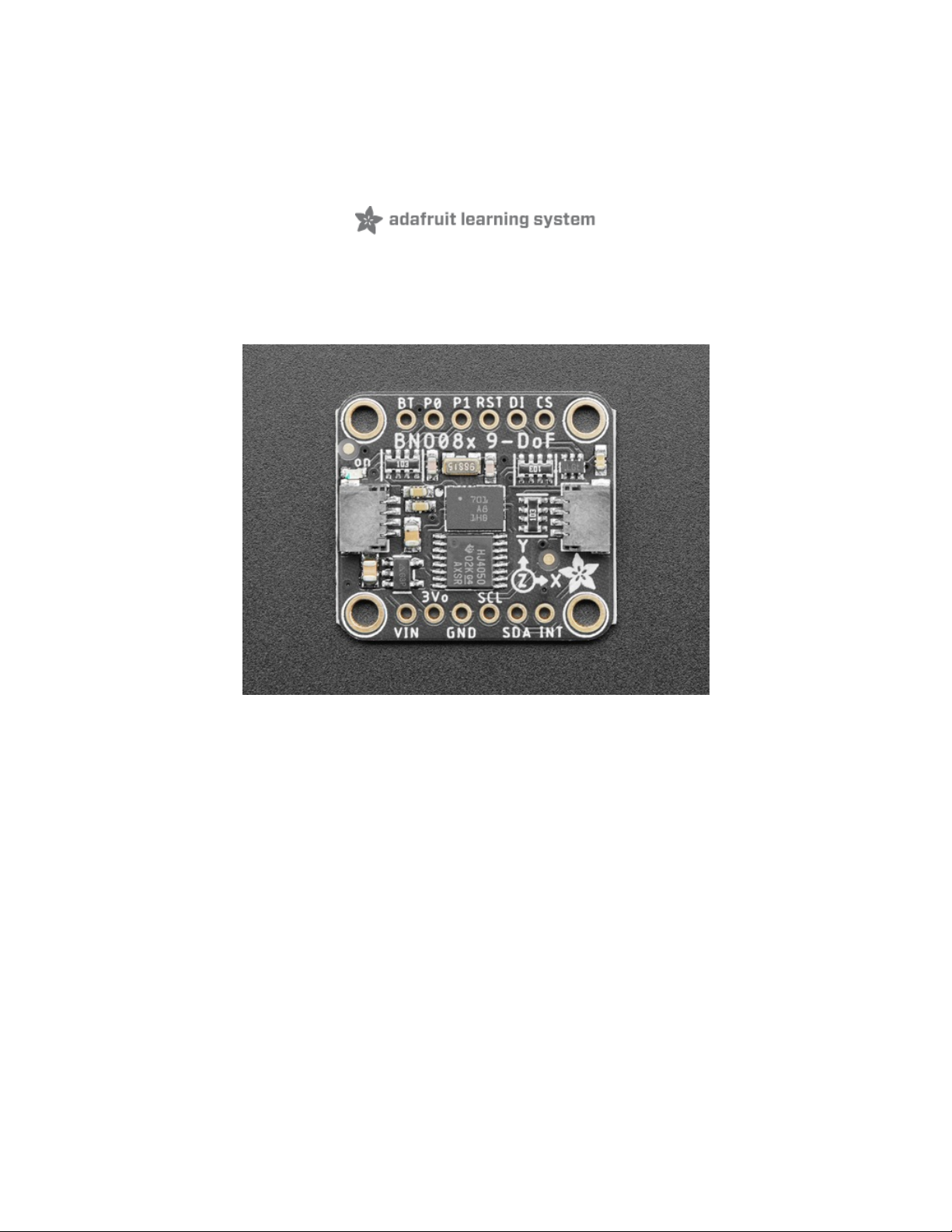
Adafruit 9-DOF Orientation IMU Fusion Breakout - BNO085
Created by Bryan Siepert
Last updated on 2020-10-14 11:43:08 AM EDT
Page 2
Overview
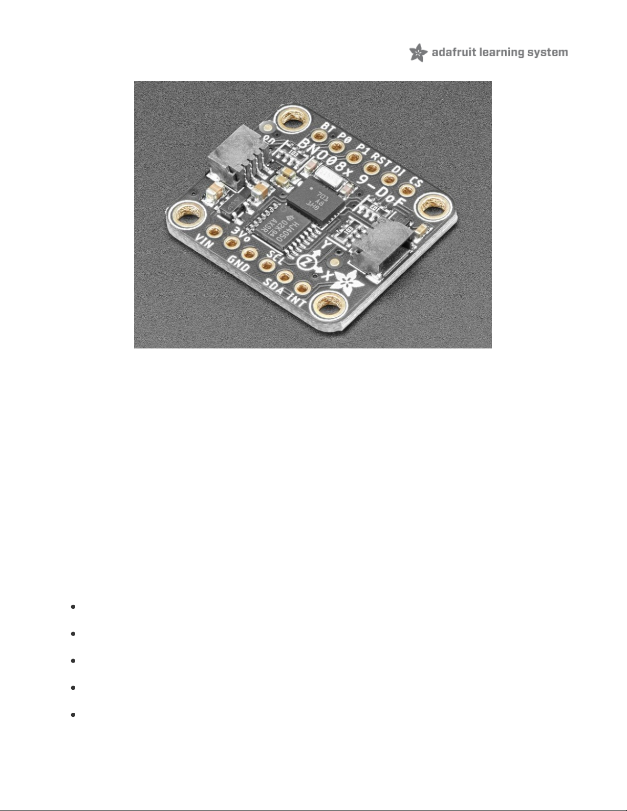
Here it is, the motion sensor you were looking for: the one that just gives you the directly usable information without
requiring you to first consult with a PhD to learn the arcane arts of Sensor Fusion. The BNO085 takes the life's work of
multiple people who have spent their entire career focused on how to get useful information from direct motion sensor
measurements and then squeezes that information down into a 5.2x3.8mm box, along with the sensors to go along
with it.
The BNO085 by the motion sensing experts at Hillcrest Laboratories takes the familiar 3-axis accelerometers,
gyroscopes, and magnetometers and packages then alongside an Arm Cortex M0 processor running Hillcrest's SH-2
firmware that handles the work of reading the sensors, fusing the measurements into data that you can use directly,
and packaging that data and delivering it to you. If the name and description of the BNO085 sounds strikingly similar
to those of the BNO055 by Bosch Sensortec, there is a good reason why: they're the same thing, but also they're not.
Thanks to a unique agreement between Bosch and Hillcrest, the BNO085 uses the
same hardware
as the BNO055
but
very different firmware
running on it.
"How different?" you might ask. Well my friend, pull up a chair and grab a box of popcorn because it's quite a list. First
let's list the similarities. The BNO055 and BNO085 can both deliver the following types of sensor data and sensor
fusion products:
Acceleration Vector / Accelerometer
Three axes of acceleration (gravity + linear motion) in m/s^2
Angular Velocity Vector / Gyro
Three axes of 'rotation speed' in rad/s
Magnetic Field Strength Vector / Magnetometer
Three axes of magnetic field sensing in micro Tesla (uT)
Linear Acceleration Vector
Three axes of linear acceleration data (acceleration minus gravity) in m/s^2
Gravity Vector
Three axes of gravitational acceleration (minus any movement) in m/s^2
© Adafruit Industries
https://learn.adafruit.com/adafruit-9-dof-orientation-imu-fusion-breakout-
bno085
Page 4 of 41
Page 3
Absolute Orientation / Rotation Vector
Four-point quaternion output for accurate data manipulation
Thanks to the sensor fusion and signal processing wizards from Hillcrest, with the BNO085 you also get:
Application Optimized Rotation Vectors
For AR/VR, low latency, and low power consumption
Additional Base Sensor Reports
Separate and simultaneous outputs of Calibrated, Uncalibrated + Correction, and Raw ADC outputs for the
Accelerometer, Gyro, and Magnetometer
Detection and Classification reports:
Stability Detection and Classification
Significant Motion Detector
Tap, Step, and Shake Detectors
Activity Classification
As if the above wasn't enough, the BNO085 also provides an impressive suite of detection and classification products
by further analyzing the measured motion:
Stability Detection and Classification
Tap Detector
Step Detector
Step Counter
Activity Classification
Significant Motion Detector
Shake Detector
More information about the various report types is available on the Report Types (https://adafru.it/N-A) page
© Adafruit Industries
https://learn.adafruit.com/adafruit-9-dof-orientation-imu-fusion-breakout-
bno085
Page 5 of 41
Page 4
A firehose of information in a human-friendly package
The BNO085 is a supremely capable sensor, practically overflowing with useful information. It is also very small. As the
Ideal Gas Law (https://adafru.it/N-B) tells us, when you shove a lot of stuff into a small space, things are going to get a
bit spicy. Worry not fellow scientist, we here at Adafruit have done our part to make the BNO085 as approachable as
possible. It's a pretty familiar recipe:
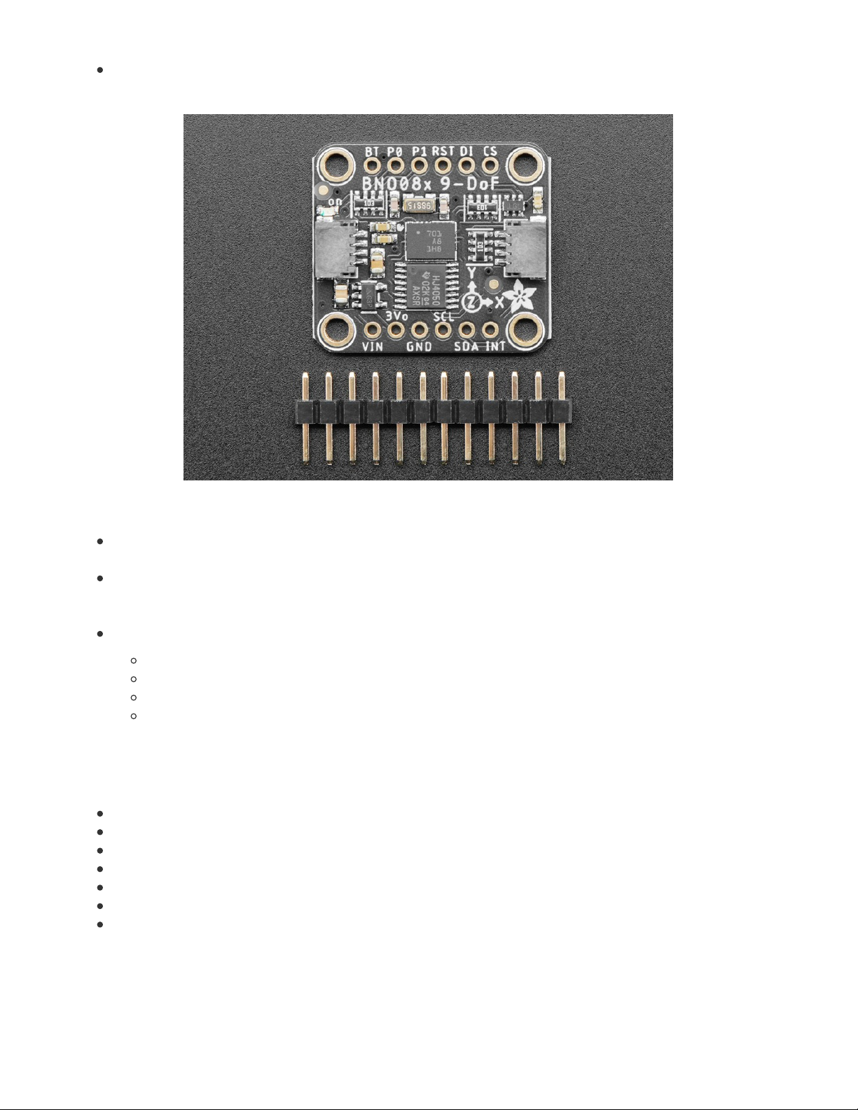
Take the following and mix in Eagle CAD:
One part raw unprocessed Hillcrest Labs brand BNO085
One voltage regulator for flexible input voltage
One part Level shifting circuitry for use with 3.3V (RPi/Feather) or 5V(Arduino) logic levels
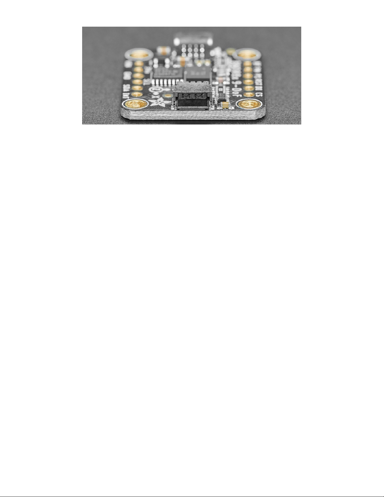
Two handy dandy Stemma QT connectors for solderless connection
One, 32.768kHz crystal to provide a stable reference oscillation
One breakout PCB with breadboard friendly headers
Prepare in the pick and place and bake in a reflow oven on High for about 5 minutes and you get the Adafruit
BNO085 IMU breakout.
With the physical hardware tamed and made approachable, that leaves the software. If it wasn't already very obvious,
the BNO085 can generate a wide selection of data and as a result, it has a slightly complex and unique way of
delivering that information. To save you the effort of figuring out how to decode and organize all those measurements,
we've written libraries for you to use with CircuitPython and Arduino. Just plug in the sensor to your favorite device
using our wiring examples, and install the library for your chosen platform and you're ready to start building your very
own Robot Friend.
As an alternative to the cornucopia of vectors and classifications that the standard sensor hub modes provide, the
BN0085 also provides a simple but useful and well executed UART-based mode that provides calibrated heading and
acceleration measurements. The UART-RVC mode takes its acronym from one of its potential applications: Robot
Vacuum Cleaners. This mode is exceedingly simple to interface with, and based on my limited testing, it performs
astoundingly well. The ease of use to utility ratio here is off the charts.
We've written libraries for the UART RVC mode for both Arduino and CircuitPython/Python. Check out the UART RVC
pages for Arduino (https://adafru.it/N-C) and Python (https://adafru.it/N-D) for wiring diagrams and example code
© Adafruit Industries
https://learn.adafruit.com/adafruit-9-dof-orientation-imu-fusion-breakout-
bno085
Page 6 of 41
Page 5
© Adafruit Industries
https://learn.adafruit.com/adafruit-9-dof-orientation-imu-fusion-breakout-
bno085
Page 7 of 41
Page 6
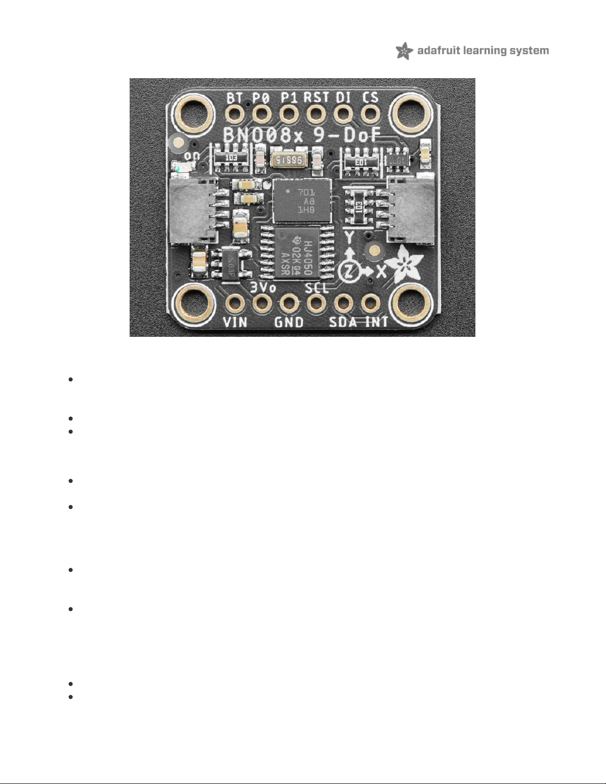
Pinouts
Power Pins
VIN - this is the power pin. Since the sensor chip uses 3 VDC, we have included a voltage regulator on board that
will take 3-5VDC and safely convert it down. To power the board, give it the same power as the logic level of
your microcontroller - e.g. for a 5V microcontroller like Arduino, use 5V
3Vo - this is the 3.3V output from the voltage regulator, you can grab up to 100mA from this if you like
GND - common ground for power and logic
I2C Logic Pins
SCL - I2C clock pin, connect to your microcontroller I2C clock line. This pin is level shifted so you can use 3-5V
logic, and there's a 10K pullup on this pin.
SDA - I2C data pin, connect to your microcontroller I2C data line. This pin is level shifted so you can use 3-5V
logic, and there's a 10K pullup on this pin.
Optional:
STEMMA QT (https://adafru.it/Ft4) - A solderless alternative to the Vin, GND, SCL, and SDA pins. These
connectors allow you to connectors to dev boards with STEMMA QT connectors and various associated
accessories (https://adafru.it/Ft6)
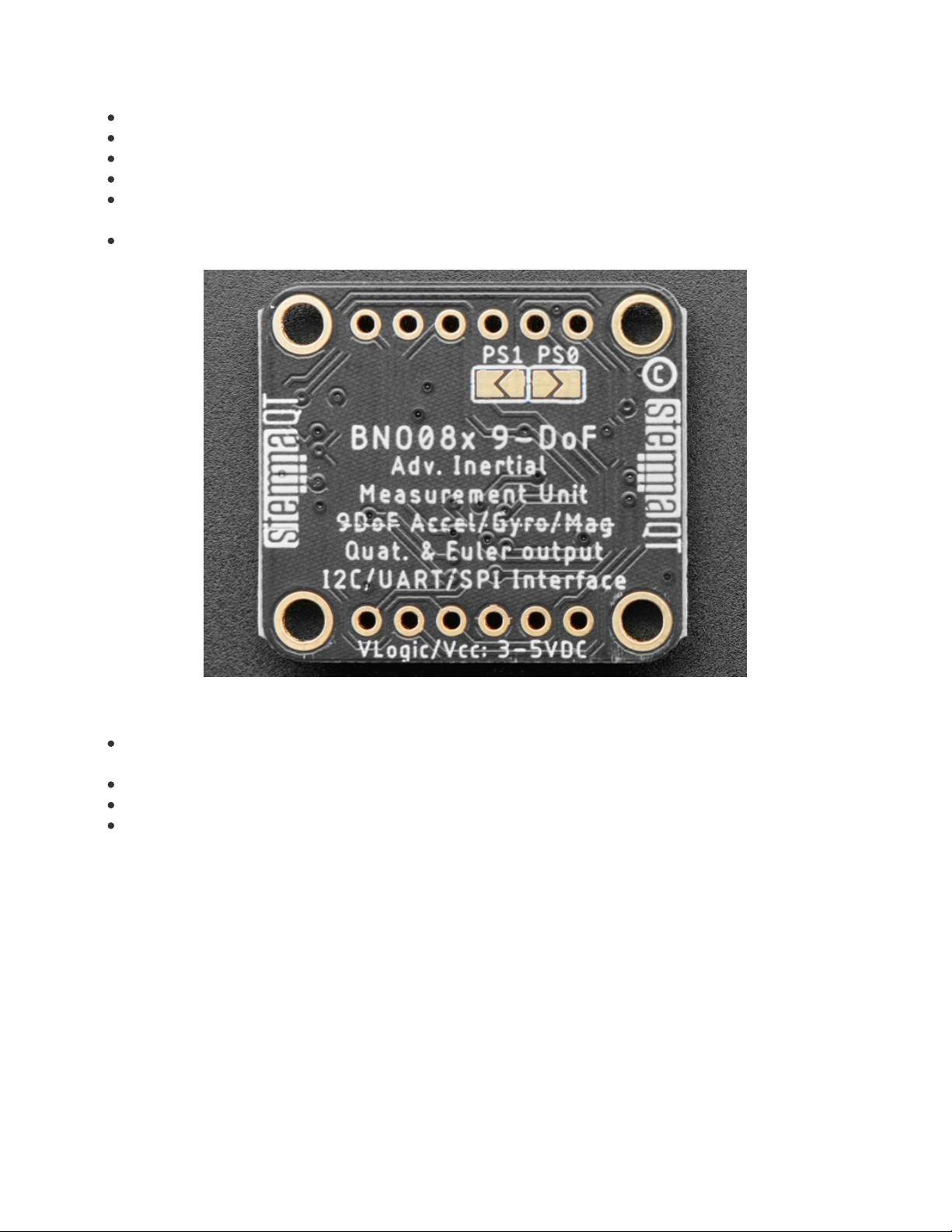
DI - I2C Address pin. Pulling this pin high or bridging the solder jumper on the back will change the I2C address
from 0x4A to 0x4B
UART Logic Pins
SCL - UART TX- Connect to your microcontroller RX pin
SDA - UART RX- Connect to your microcontroller TX pin
© Adafruit Industries
https://learn.adafruit.com/adafruit-9-dof-orientation-imu-fusion-breakout-
bno085
Page 8 of 41
Page 7
SPI Logic pins:
SCL - This is
also
the SPI Clock pin / SCK, it's an input to the chip
SDA - Doubles as the Data Out / Microcontroller In Sensor Out / MISO pin, for data sent from the BNO08x
DI - Datal In / Microcontroller Out Sensor In / MOSI pin, for data sent from your processor to the BNO08x
CS - this is the Chip Select pin, pull it low to start an SPI transaction. It's an input to the chip
INT - Interrupt- Active Low. Indicates that the BNO085 needs the host's attention. Required for stable SPI
operation
RST- Reset- Active Low - Pull low to GND to reset the sensor. Required for stable SPI operation
Other Pins
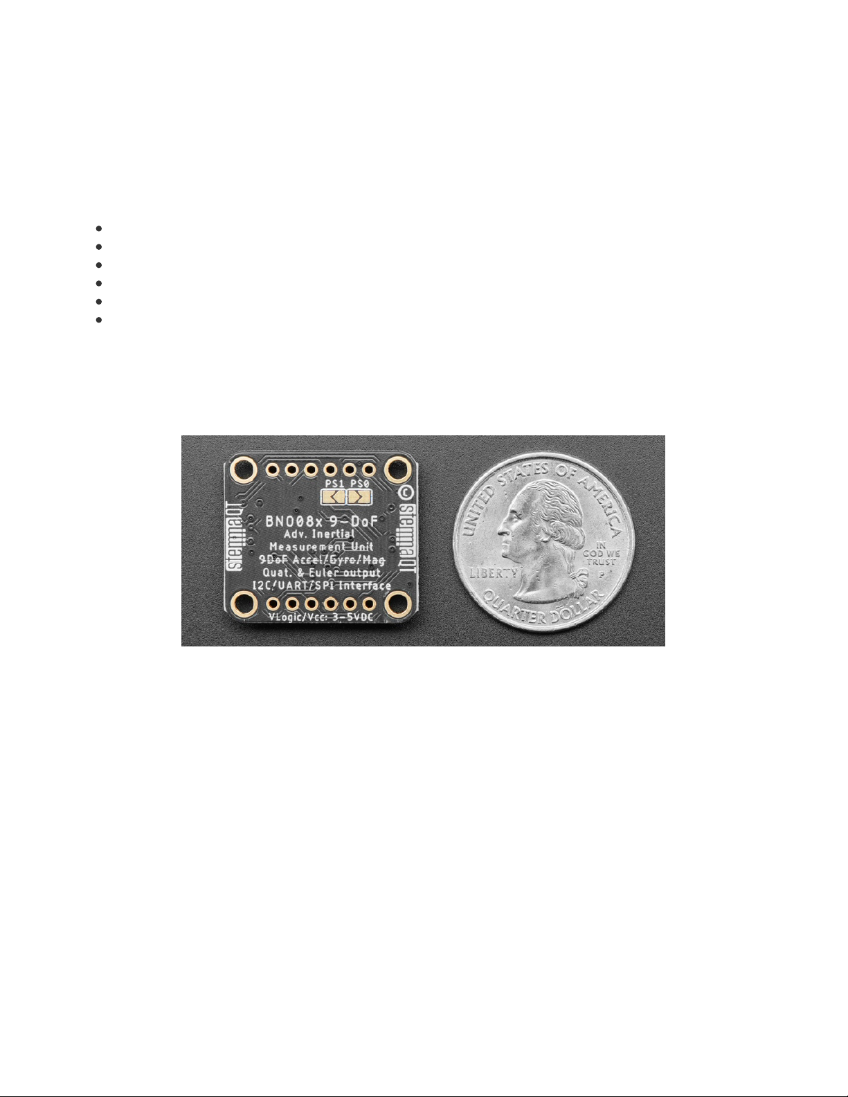
P0/P1 Pins and Solder Jumpers - Mode select. Use these pins to set the BNO085's operating mode according to
the table below. Both pins are pulled low by default, defaulting to I2C
RST- Reset, Active Low. Pull low to GND to reset the sensor
INT - Interrupt/Data Ready-Active Low pin. Indicates that the BNO085 needs the host's attention
BT- Bootloader pin used to put the sensor in bootloader. EXPERT USERS should consult the datasheet for more
information. If you don't know what this you probably want to just leave it be or risk damaging your sensor
© Adafruit Industries
https://learn.adafruit.com/adafruit-9-dof-orientation-imu-fusion-breakout-
bno085
Page 9 of 41
Page 8

PS1 PS0 Mode
Low Low I2C
Low High UART-RVC
High Low UART
High High SPI
© Adafruit Industries
https://learn.adafruit.com/adafruit-9-dof-orientation-imu-fusion-breakout-
bno085
Page 10 of 41
Page 9

Arduino
Using the BNO08x with Arduino is a simple matter of wiring up the sensor to your Arduino-compatible microcontroller,
installing the Adafruit BNO08x (https://adafru.it/N-E) library, and running the provided example code.
I2C Wiring
Use this wiring if you want to connect via I2C interface. The default I2C address for the BNO08x is 0x4A but it can be
switched to 0x4B by pulling the DI pin high to VCC.
Here is how to wire up the sensor using one of the STEMMA QT (https://adafru.it/Ft4) connectors. The examples show
a Metro but wiring will work the same for an Arduino or other compatible board.
Connect board VIN (red wire) to Board 3V
Connect board GND (black wire) to Board
GND
Connect board SCL (yellow wire) to Board SCL
Connect board SDA (blue wire) to Board SDA
Here is how to wire the sensor to a board using a solderless breadboard:
Because of the size and complexity of the BNO08x library, you will have to use an Arduino-compatible with a
larger amount of memory such as the SAMD21, SAMD51, nRF52, ESP, Mega, etc. Arduino Uno or Leonardo
will not work due to minimal RAM
The examples below show Metro and Feather M4s, and reference their 3.3V logic level for power
connections. If using a board with a 5V logic level, connect the BNO085 Vin to 5V instead
© Adafruit Industries
https://learn.adafruit.com/adafruit-9-dof-orientation-imu-fusion-breakout-
bno085
Page 11 of 41
Page 10
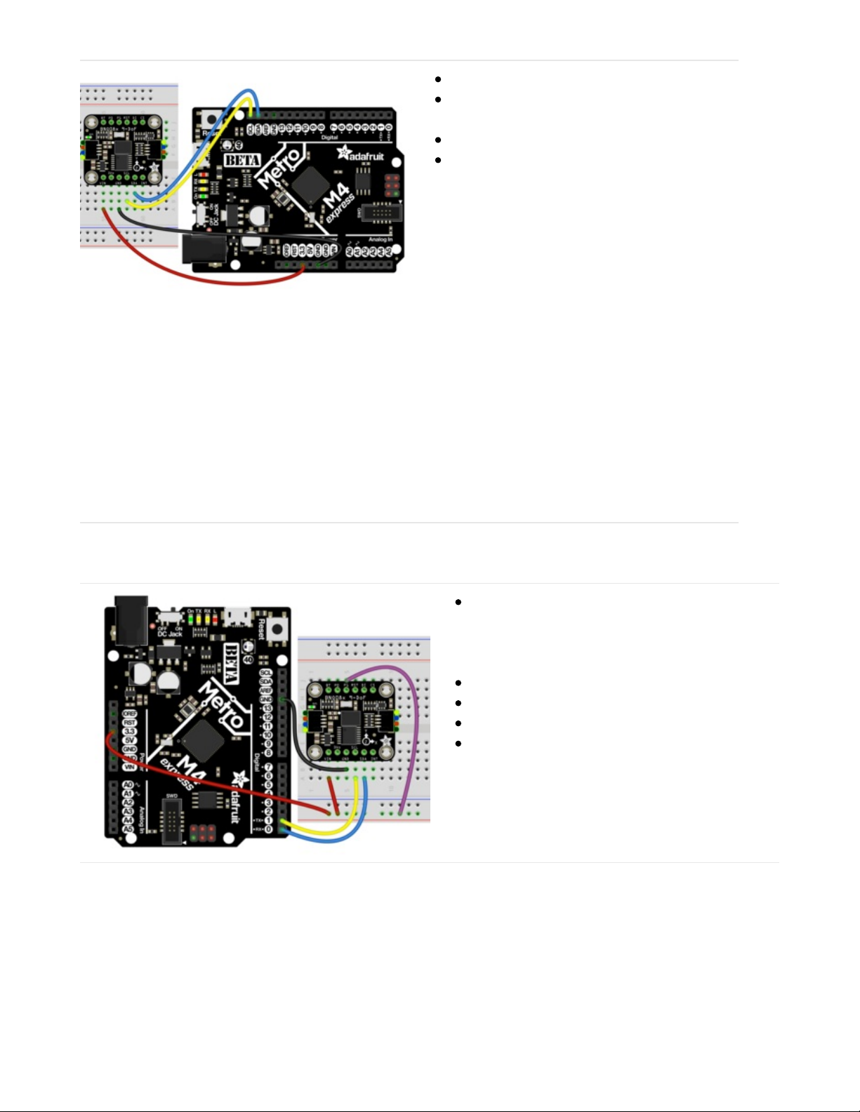
Connect board VIN (red wire) to Board 3V
Connect board GND (black wire) to Board
GND
Connect board SCL (yellow wire) to Board SCL
Connect board SDA (blue wire) to Board SDA
UART Wiring
BNO085 Vin to the power supply, using the same
logic level as your microcontroller. For the Metro
M4 shown that is 3.3V, however check your
board's documentation to be sure
BNO085 GND to board GND
BNO085 SCL to board TX
BNO085 SDA to board RX
BNO085 P1 to Board Power supply
SPI Wiring
Finally for SPI we are using a Feather M4 for the wiring diagram to make it easier to read. If using an Arduino
compatible or other different shaped board, you will still connect to the same pin names to ensure that you use
hardware SPI
© Adafruit Industries
https://learn.adafruit.com/adafruit-9-dof-orientation-imu-fusion-breakout-
bno085
Page 12 of 41
Page 11
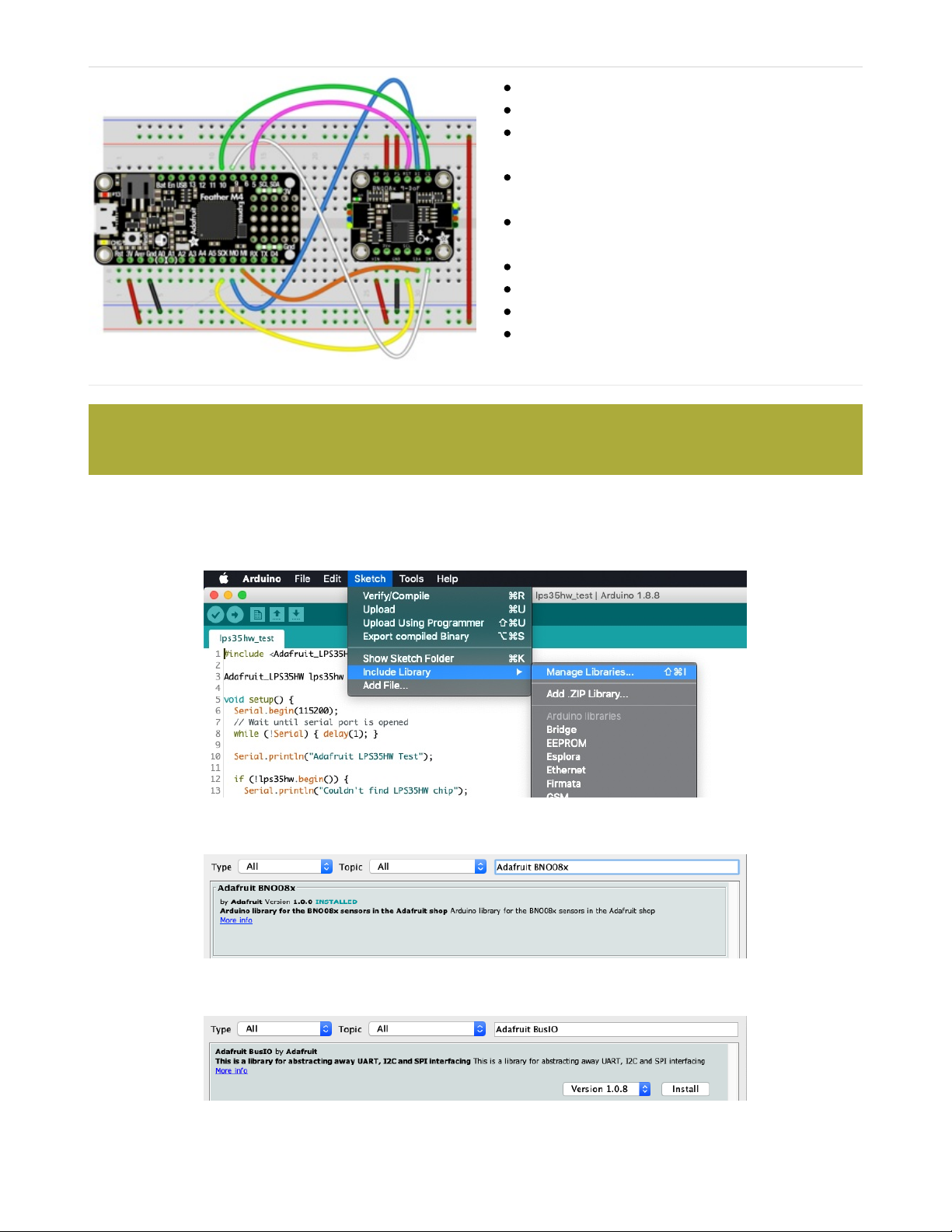
BNO085 Vin to 3V on the Feather M4
BNO085 GND to common power/data ground
BNO085 SCL to the SPI SCK pin on the Feather
M4
BNO085 SDA pin to the SPI MISO pin on the
Feather M4
BNO085 DI to the SPI MOSI pin on the Feather
M4
BNO085 CS to pin #10 on the Feather M4
BNO085 INT to pin #9 on the Feather M4
BNO085 RST to pin #5 on the Feather M4
BNO085 P0 and P1 to 3V on the Feather M4
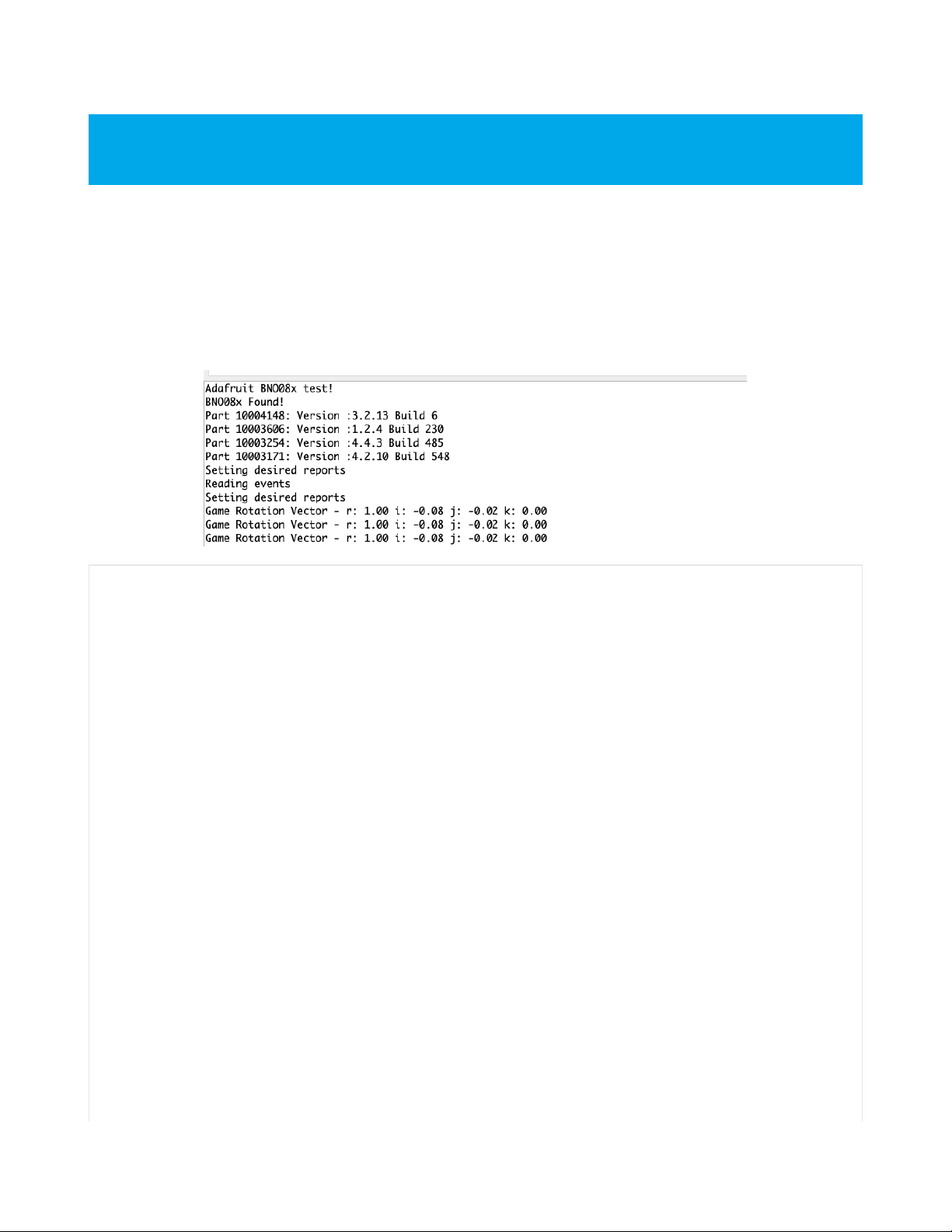
Library Installation
You can install the Adafruit BNO08x library for Arduino using the Library Manager in the Arduino IDE.
Click the Manage Libraries ... menu item, search for Adafruit BNO08x, and select the Adafruit BNO08x library:
Follow the same process for the Adafruit BusIO library.
This is a lot of wires! You may be tempted to omit the INT and RST pin connections but do not! They are
required for a good SPI connection
© Adafruit Industries
https://learn.adafruit.com/adafruit-9-dof-orientation-imu-fusion-breakout-
bno085
Page 13 of 41
Page 12
Load Example
Open up File -> Examples -> Adafruit BNO08x -> rotation_vector
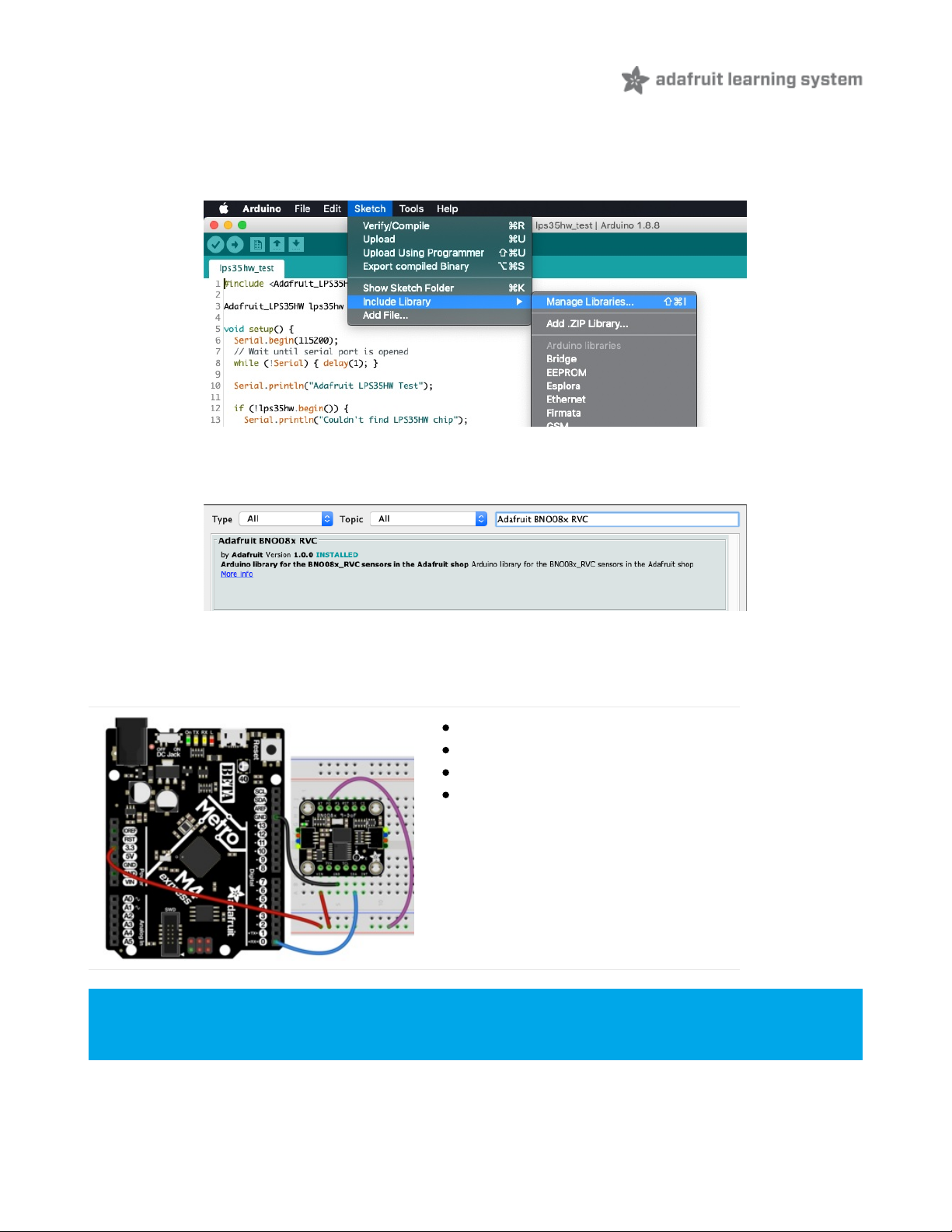
After opening the demo file, upload the compiled code to your Arduino wired up to the sensor. Once you upload the
code, you will see the rotation vector quaternion values being printed when you open the Serial Monitor (Tools-
>Serial Monitor) at 115200 baud, similar to this:
Example Code
// Basic demo for readings from Adafruit BNO08x
#include <Adafruit_BNO08x.h>
// For SPI mode, we need a CS pin
#define BNO08X_CS 10
#define BNO08X_INT 9
#define BNO08X_RESET 5
Adafruit_BNO08x bno08x(BNO08X_RESET);
sh2_SensorValue_t sensorValue;
void setup(void) {
Serial.begin(115200);
while (!Serial) delay(10); // will pause Zero, Leonardo, etc until serial console opens
Serial.println("Adafruit BNO08x test!");
// Try to initialize!
if (!bno08x.begin_I2C()) {
//if (!bno08x.begin_UART(&Serial1)) { // Requires a device with > 300 byte UART buffer!
//if (!bno08x.begin_SPI(BNO08X_CS, BNO08X_INT)) {
Serial.println("Failed to find BNO08x chip");
while (1) { delay(10); }
}
Serial.println("BNO08x Found!");
for (int n = 0; n < bno08x.prodIds.numEntries; n++) {
Serial.print("Part ");
Serial.print(bno08x.prodIds.entry[n].swPartNumber);
Serial.print(": Version :");
This example shows the Rotation Vector report however there are *many* more. See the Report Types page
for more information
© Adafruit Industries
https://learn.adafruit.com/adafruit-9-dof-orientation-imu-fusion-breakout-
bno085
Page 14 of 41
Page 13

Serial.print(": Version :");
Serial.print(bno08x.prodIds.entry[n].swVersionMajor);
Serial.print(".");
Serial.print(bno08x.prodIds.entry[n].swVersionMinor);
Serial.print(".");
Serial.print(bno08x.prodIds.entry[n].swVersionPatch);
Serial.print(" Build ");
Serial.println(bno08x.prodIds.entry[n].swBuildNumber);
}
setReports();
Serial.println("Reading events");
delay(100);
}
// Here is where you define the sensor outputs you want to receive
void setReports(void) {
Serial.println("Setting desired reports");
if (! bno08x.enableReport(SH2_GAME_ROTATION_VECTOR)) {
Serial.println("Could not enable game vector");
}
}
void loop() {
delay(10);
if (bno08x.wasReset()) {
Serial.print("sensor was reset ");
setReports();
}
if (! bno08x.getSensorEvent(&sensorValue)) {
return;
}
switch (sensorValue.sensorId) {
case SH2_GAME_ROTATION_VECTOR:
Serial.print("Game Rotation Vector - r: ");
Serial.print(sensorValue.un.gameRotationVector.real);
Serial.print(" i: ");
Serial.print(sensorValue.un.gameRotationVector.i);
Serial.print(" j: ");
Serial.print(sensorValue.un.gameRotationVector.j);
Serial.print(" k: ");
Serial.println(sensorValue.un.gameRotationVector.k);
break;
}
}
© Adafruit Industries
https://learn.adafruit.com/adafruit-9-dof-orientation-imu-fusion-breakout-
bno085
Page 15 of 41
Page 14
UART-RVC for Arduino
Library Installation
You can install the Adafruit BNO08x RVC library for Arduino using the Library Manager in the Arduino IDE.
Click the Manage Libraries ... menu item, search for Adafruit BNO08x RVC, and select the Adafruit BNO08x RVC
library:
UART RVC Wiring
Wiring up the BNO085 in UART RVC is similar to UART, but with one less wire!
Board 3V to BNO085 Vin (Red Wire).
Board GND to BNO085 GND (Black Wire)
Board RX to BNO085 SDA (Blue Wire)
Board 3V to BNO085 P0 (Purple Wire
Load Example - Serial Console
For an even simpler hardware setup, bridge the P0 solder jumper on the back of the board to keep it
configured in UART RVC. mode. You can always remove the solder to use other modes!
© Adafruit Industries
https://learn.adafruit.com/adafruit-9-dof-orientation-imu-fusion-breakout-
bno085
Page 16 of 41
Page 15
Open up File -> Examples -> Adafruit BNO08x RVC-> uart_rvc
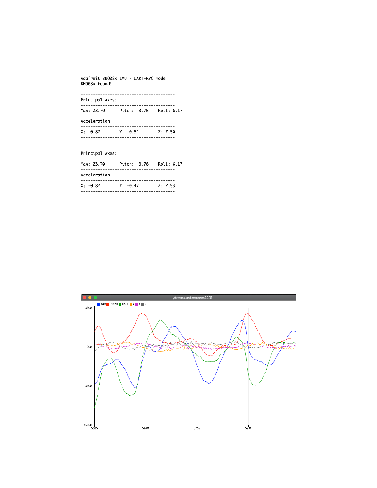
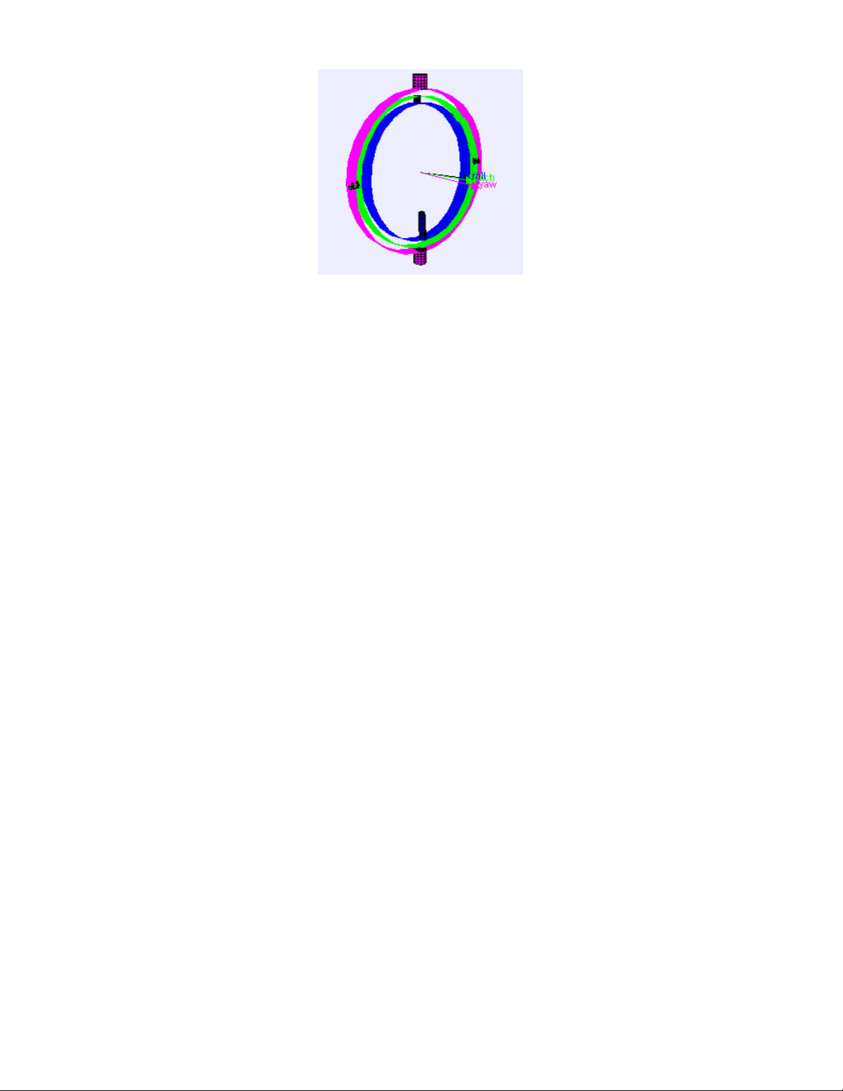
After opening the demo file, upload to your Arduino wired up to the sensor. Once you upload the code, you will see
the heading principal axes and acceleration values being printed when you open the Serial Monitor (Tools->Serial
Monitor) at 115200 baud, similar to this:
Load Example - Serial Plotter
In addition to the text based example code shown above, we have also included a version that is formatted to display
nicely in the Arduino Serial Plotter.
Open up File -> Examples -> Adafruit BNO08x RVC-> uart_rvc_plotter
After opening the demo file, upload to your Arduino wired up to the sensor. Once you upload the code, open the Serial
Plotter (Tools->Serial Plotter) at 115200 baud and you will see graphs of the heading and acceleration like these:
© Adafruit Industries
https://learn.adafruit.com/adafruit-9-dof-orientation-imu-fusion-breakout-
bno085
Page 17 of 41
Page 16

Play around with it! Move the sensor around and see how rolling back and forth, front to back, and twisting change the
graphs. I think you'll be pleasantly surprised!
© Adafruit Industries
https://learn.adafruit.com/adafruit-9-dof-orientation-imu-fusion-breakout-
bno085
Page 18 of 41
Page 17

/* Test sketch for Adafruit BNO08x sensor in UART-RVC mode */
#include "Adafruit_BNO08x_RVC.h"
Adafruit_BNO08x_RVC rvc = Adafruit_BNO08x_RVC();
void setup() {
// Wait for serial monitor to open
Serial.begin(115200);
while (!Serial)
delay(10);
Serial.println("Adafruit BNO08x IMU - UART-RVC mode");
Serial1.begin(115200); // This is the baud rate specified by the datasheet
while (!Serial1)
delay(10);
if (!rvc.begin(&Serial1)) { // connect to the sensor over hardware serial
Serial.println("Could not find BNO08x!");
while (1)
delay(10);
}
Serial.println("BNO08x found!");
}
void loop() {
BNO08x_RVC_Data heading;
if (!rvc.read(&heading)) {
return;
}
Serial.println();
Serial.println(F("---------------------------------------"));
Serial.println(F("Principal Axes:"));
Serial.println(F("---------------------------------------"));
Serial.print(F("Yaw: "));
Serial.print(heading.yaw);
Serial.print(F("\tPitch: "));
Serial.print(heading.pitch);
Serial.print(F("\tRoll: "));
Serial.println(heading.roll);
Serial.println(F("---------------------------------------"));
Serial.println(F("Acceleration"));
Serial.println(F("---------------------------------------"));
Serial.print(F("X: "));
Serial.print(heading.x_accel);
Serial.print(F("\tY: "));
Serial.print(heading.y_accel);
Serial.print(F("\tZ: "));
Serial.println(heading.z_accel);
Serial.println(F("---------------------------------------"));
// delay(200);
}
© Adafruit Industries
https://learn.adafruit.com/adafruit-9-dof-orientation-imu-fusion-breakout-
bno085
Page 19 of 41
Page 18
© Adafruit Industries
https://learn.adafruit.com/adafruit-9-dof-orientation-imu-fusion-breakout-
bno085
Page 20 of 41
Page 19

Arduino
Docs
Arduino Docs (https://adafru.it/Nxf)
© Adafruit Industries
https://learn.adafruit.com/adafruit-9-dof-orientation-imu-fusion-breakout-
bno085
Page 21 of 41
Page 20

Arduino UART RVC
Docs
Arduino UART RVC Docs (https://adafru.it/NxD)
© Adafruit Industries
https://learn.adafruit.com/adafruit-9-dof-orientation-imu-fusion-breakout-
bno085
Page 22 of 41
Page 21
Python & CircuitPython
It's easy to use the BNO08x with Python or CircuitPython, and the Adafruit CircuitPython BNO08x (https://adafru.it/N-F)
module. This module allows you to easily write Python code that reads humidity and temperature from the BNO08x
sensor.
You can use this sensor with any CircuitPython microcontroller board or with a computer that has GPIO and Python
thanks to Adafruit_Blinka, our CircuitPython-for-Python compatibility library (https://adafru.it/BSN).
CircuitPython I2C Wiring
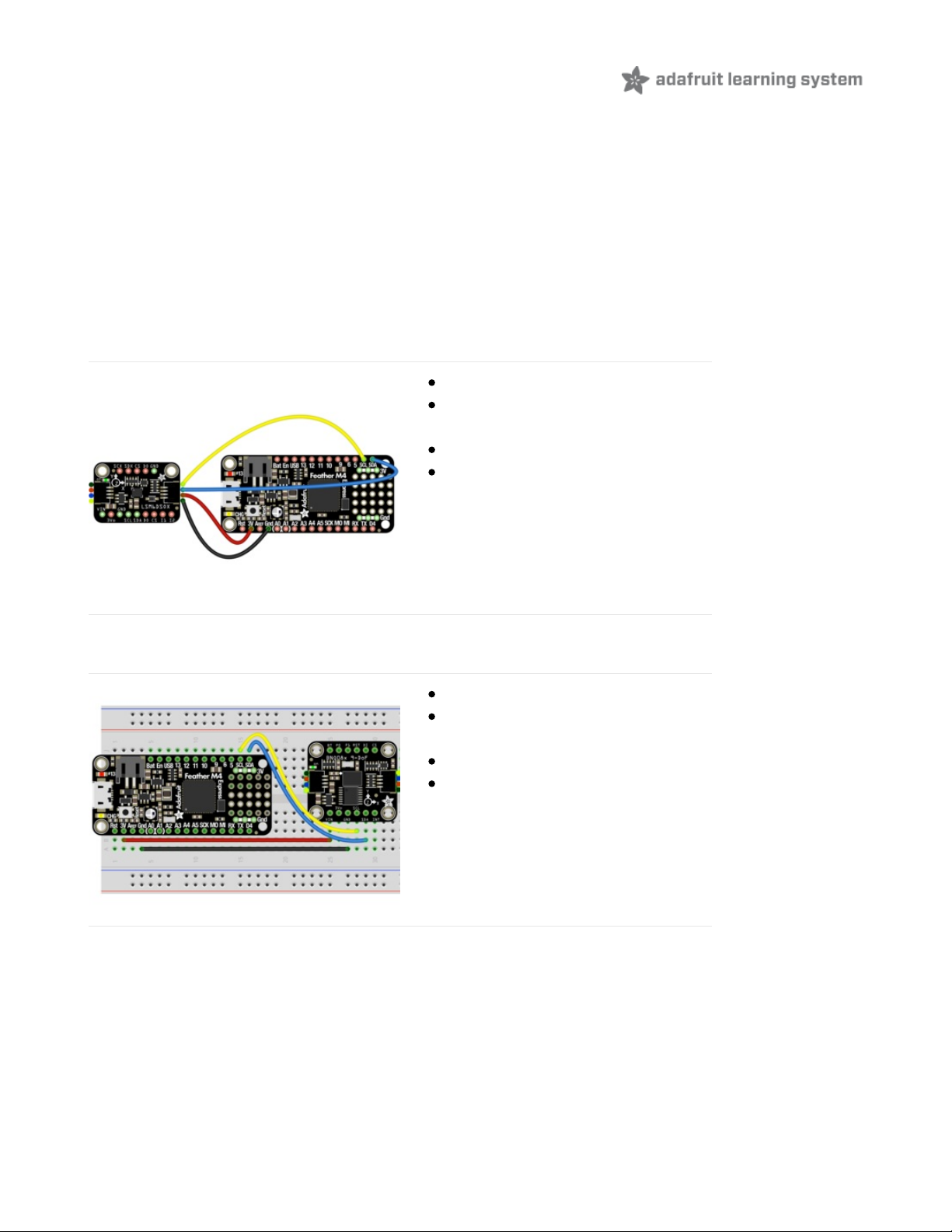
First wire up a BNO08x to your board exactly as shown below. Here's an example of wiring a Feather M4 to the sensor
with I2C using one of the handy STEMMA QT (https://adafru.it/Ft4) connectors:
Board 3V to sensor VIN (red wire)
Board GND to sensor GND (black
wire)
Board SCL to sensor SCL (yellow wire)
Board SDA to sensor SDA (blue wire)
You can also use the standard 0.100"/2.54mm pitch headers to wire it up on a breadboard:
Board 3V to sensor VIN (red wire)
Board GND to sensor GND (black
wire)
Board SCL to sensor SCL (yellow wire)
Board SDA to sensor SDA (blue wire)
CircuitPython UART Wiring
If you wish to use UART, you can enable the UART mode by pulling the P1 pin high and connecting the sensor to your
RX and TX pins:
© Adafruit Industries
https://learn.adafruit.com/adafruit-9-dof-orientation-imu-fusion-breakout-
bno085
Page 23 of 41
Page 22
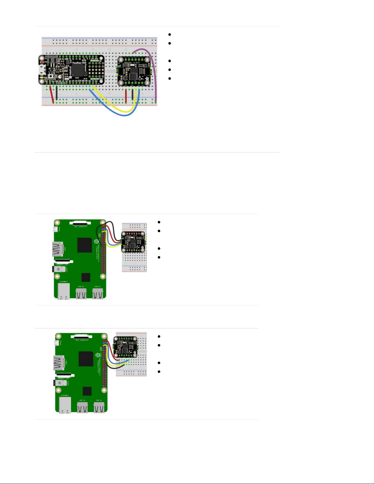
Board 3V to sensor VIN (red wire)
Board GND to sensor GND (black
wire)
Board TX to sensor SCL (yellow wire)
Board RX to sensor SDA (blue wire)
Board 3V to sensor P1 (purple wire)
Python Computer Wiring
Since there's
dozens
of Linux computers/boards you can use, we will show wiring for Raspberry Pi. For other platforms,
please visit the guide for CircuitPython on Linux to see whether your platform is supported (https://adafru.it/BSN).
Here's the Raspberry Pi wired to the sensor using I2C and a STEMMA QT (https://adafru.it/Ft4) connector:
Pi 3V to sensor VCC (red wire)
Pi GND to sensor GND (black
wire)
Pi SCL to sensor SCL (yellow wire)
Pi SDA to sensor SDA (blue wire)
Finally here is an example of how to wire up a Raspberry Pi to the sensor using a solderless breadboard
Pi 3V to sensor VCC (red wire)
Pi GND to sensor GND (black
wire)
Pi SCL to sensor SCL (yellow wire)
Pi SDA to sensor SDA (blue wire)
Python UART Wiring
© Adafruit Industries
https://learn.adafruit.com/adafruit-9-dof-orientation-imu-fusion-breakout-
bno085
Page 24 of 41
Page 23
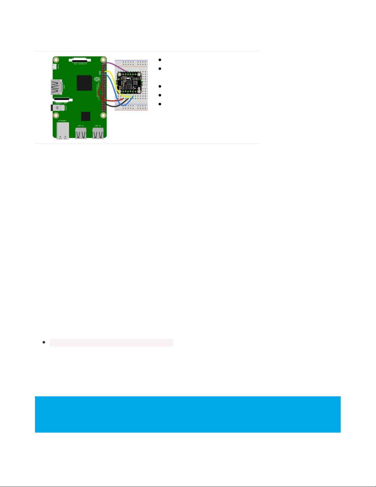
If you wish to use UART, you can enable the UART mode by pulling the P1 pin high and connecting the sensor to your
RX and TX pins:
Pi 3V3 to sensor VIN (red wire)
Pi GND to sensor GND (black
wire)
Pi TX to sensor SCL (yellow wire)
Pi RX to sensor SDA (blue wire)
Pi 3V3 to sensor P1 (purple wire)
CircuitPython Installation of BNO08x Library
You'll need to install the Adafruit CircuitPython BNO08x (https://adafru.it/N-F) library on your CircuitPython board.
First make sure you are running the latest version of Adafruit CircuitPython (https://adafru.it/Amd) for your board.
Next you'll need to install the necessary libraries to use the hardware--carefully follow the steps to find and install these
libraries from Adafruit's CircuitPython library bundle (https://adafru.it/ENC). Our CircuitPython starter guide has a great
page on how to install the library bundle (https://adafru.it/ABU).
Before continuing make sure your board's lib folder or root filesystem has the adafruit_BNO08x.mpy file and
adafruit_bus_device folder copied over.
Next connect to the board's serial REPL (https://adafru.it/Awz)so you are at the CircuitPython >>> prompt.
Python Installation of BNO08x Library
You'll need to install the Adafruit_Blinka library that provides the CircuitPython support in Python. This may also
require enabling I2C on your platform and verifying you are running Python 3. Since each platform is a little different,
and Linux changes often, please visit the CircuitPython on Linux guide to get your computer
ready (https://adafru.it/BSN)!
Once that's done, from your command line run the following command:
sudo pip3 install adafruit-circuitpython-bno08x
If your default Python is version 3 you may need to run 'pip' instead. Just make sure you aren't trying to use
CircuitPython on Python 2.x, it isn't supported!
CircuitPython & Python Usage
The examples below show an I2C connection displaying the Rotation Vector (Quaternion) report however
there are many more that can be enabled. See the Report Types page for more information on the available
reports
© Adafruit Industries
https://learn.adafruit.com/adafruit-9-dof-orientation-imu-fusion-breakout-
bno085
Page 25 of 41
Page 24
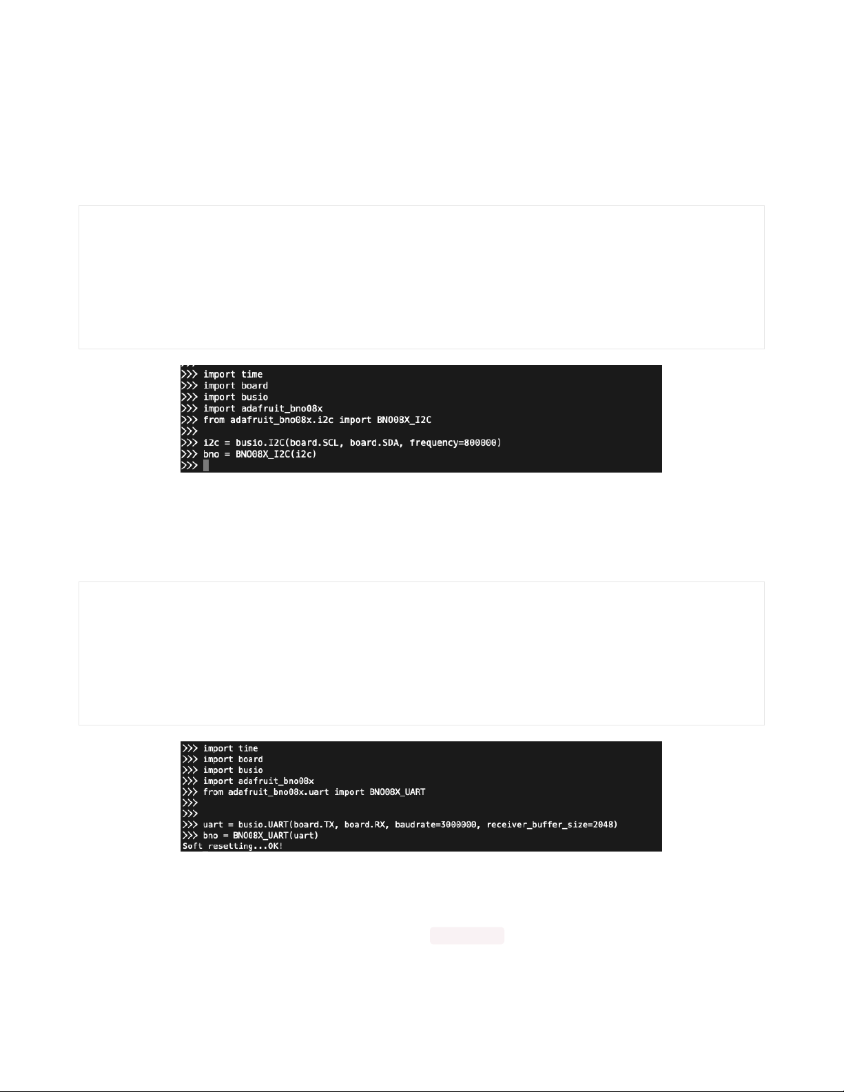
To demonstrate the usage of the sensor we'll initialize it and enable the Rotation Vector report type and display the
readings using properties in the CircuitPython REPL
I2C Initialization
If you are using the I2C connection, run the following code to import the necessary modules and initialize the I2C
connection with the sensor:
import time
import board
import busio
import adafruit_bno08x
from adafruit_bno08x.i2c import BNO08X_I2C
i2c = busio.I2C(board.SCL, board.SDA, frequency=800000)
bno = BNO08X_I2C(i2c)
UART Initialization - CircuitPython
If you are using the UART connection with a board (like a Feather) running CircuitPython, create your sensor object as
follows:
import adafruit_bno08x
from adafruit_bno08x.uart import BNO08X_UART
import board
import busio
uart = busio.UART(board.TX, board.RX, baudrate=3000000, receiver_buffer_size=2048)
bno = BNO08X_UART(uart)
UART Initialization - Python
Check how you specific board supports UART and where the port entry is created and named. For the Raspberry Pi,
this is done using the pyserial module and the UART used is /dev/serial0 . Then you create your sensor object as
follows:
© Adafruit Industries
https://learn.adafruit.com/adafruit-9-dof-orientation-imu-fusion-breakout-
bno085
Page 26 of 41
Page 25
import adafruit_bno08x
from adafruit_bno08x.uart import BNO08X_UART
import serial
uart = serial.Serial("/dev/serial0", 115200)
bno = BNO08X_UART(uart)
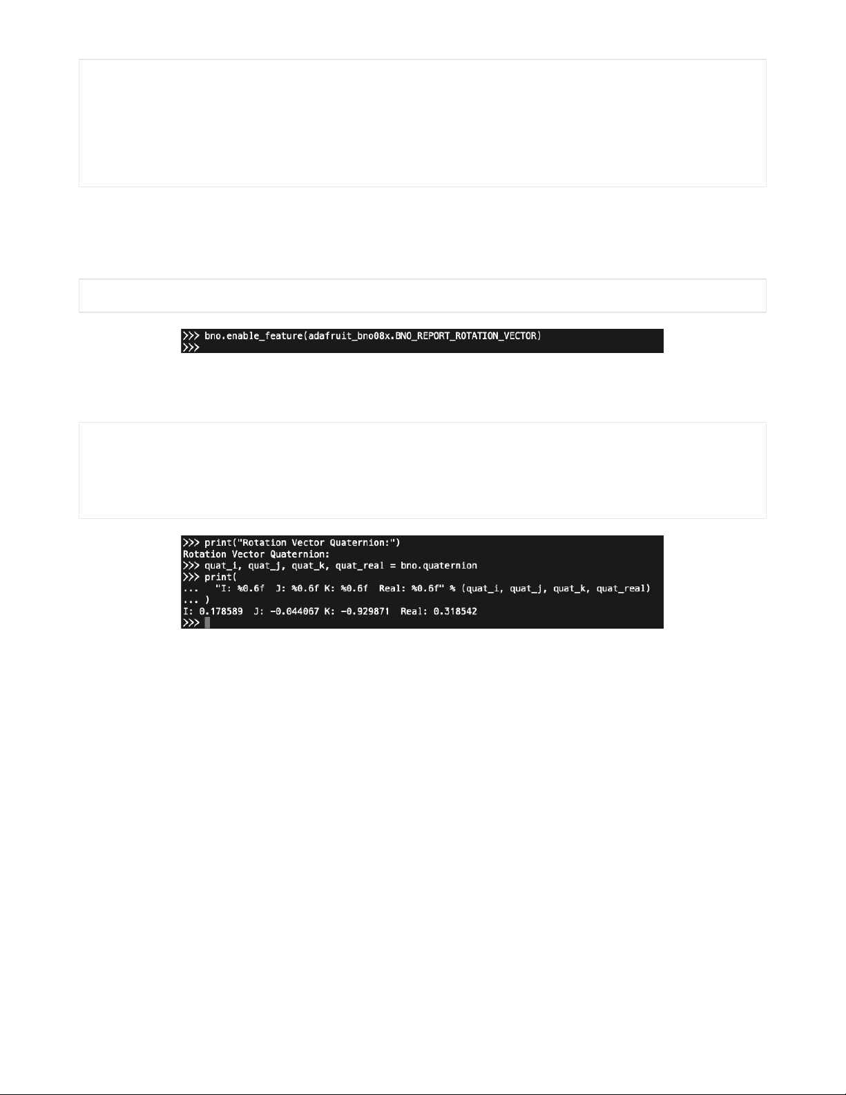
Enable the Rotation Vector/Quaternion Report
Once the connection to the sensor is established we can enable one or more report types and the associated property
bno.enable_feature(adafruit_bno08x.BNO_REPORT_ROTATION_VECTOR)
Now you're ready to read values from the sensor using the quaternion property. This is a 4-tuple of orientation
quaternion values.
print("Rotation Vector Quaternion:")
quat_i, quat_j, quat_k, quat_real = bno.quaternion
print(
"I: %0.6f J: %0.6f K: %0.6f Real: %0.6f" % (quat_i, quat_j, quat_k, quat_real)
)
Example Code
© Adafruit Industries
https://learn.adafruit.com/adafruit-9-dof-orientation-imu-fusion-breakout-
bno085
Page 27 of 41
Page 26

# SPDX-FileCopyrightText: 2020 Bryan Siepert, written for Adafruit Industries
#
# SPDX-License-Identifier: Unlicense
import time
import board
import busio
from adafruit_bno08x import (
BNO_REPORT_ACCELEROMETER,
BNO_REPORT_GYROSCOPE,
BNO_REPORT_MAGNETOMETER,
BNO_REPORT_ROTATION_VECTOR,
)
from adafruit_bno08x.i2c import BNO08X_I2C
i2c = busio.I2C(board.SCL, board.SDA, frequency=800000)
bno = BNO08X_I2C(i2c)
bno.enable_feature(BNO_REPORT_ACCELEROMETER)
bno.enable_feature(BNO_REPORT_GYROSCOPE)
bno.enable_feature(BNO_REPORT_MAGNETOMETER)
bno.enable_feature(BNO_REPORT_ROTATION_VECTOR)
while True:
time.sleep(0.5)
print("Acceleration:")
accel_x, accel_y, accel_z = bno.acceleration # pylint:disable=no-member
print("X: %0.6f Y: %0.6f Z: %0.6f m/s^2" % (accel_x, accel_y, accel_z))
print("")
print("Gyro:")
gyro_x, gyro_y, gyro_z = bno.gyro # pylint:disable=no-member
print("X: %0.6f Y: %0.6f Z: %0.6f rads/s" % (gyro_x, gyro_y, gyro_z))
print("")
print("Magnetometer:")
mag_x, mag_y, mag_z = bno.magnetic # pylint:disable=no-member
print("X: %0.6f Y: %0.6f Z: %0.6f uT" % (mag_x, mag_y, mag_z))
print("")
print("Rotation Vector Quaternion:")
quat_i, quat_j, quat_k, quat_real = bno.quaternion # pylint:disable=no-member
print(
"I: %0.6f J: %0.6f K: %0.6f Real: %0.6f" % (quat_i, quat_j, quat_k, quat_real)
)
print("")
© Adafruit Industries
https://learn.adafruit.com/adafruit-9-dof-orientation-imu-fusion-breakout-
bno085
Page 28 of 41
Page 27
UART-RVC for Python & CircuitPython
Hardware Setup
The hardware setup for the UART-RVC mode should probably be called easyware because of how simple it is. Three
wires and a solder jumper (or and additional jumper wire) and you're off to the autonomous vacuum cleaner races.
UART-RVC Wiring
To allow your device to listen to the heading and acceleration data being output by the BNO085 requires just a few
connections. It's similar to the connections for the UART mode, but because there is no software configuration of the
BNO085 required, you only need to connect your device's RX pin and pull the P0 pin high. The TX pin on your device
can be left unattached
Here we show the Wiring for a Feather M4 for CircuitPython, and a Raspberry Pi for Python:
Feather Wiring
© Adafruit Industries
https://learn.adafruit.com/adafruit-9-dof-orientation-imu-fusion-breakout-
bno085
Page 29 of 41
Page 28
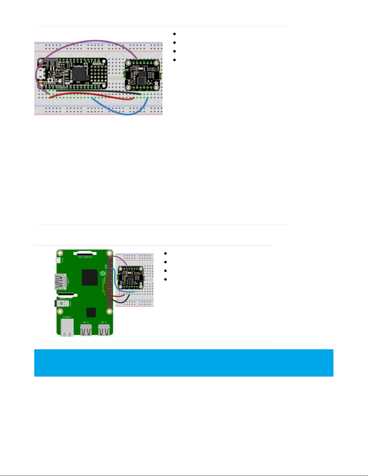
Feather 3V to BNO085 Vin (Red Wire).
Device GND to BNO085 GND (Black Wire)
Device RX to BNO085 SDA (Blue Wire)
Feather 3V to BNO085 P0 (Purple Wire).
Raspberry Pi Wiring
RPi 3V to BNO085 Vin (Red Wire).
RPi GND to BNO085 GND (Black Wire)
RPi RX to BNO085 SDA (Blue Wire)
RPi 3V to BNO085 P0 (Purple Wire)
CircuitPython Installation of BNO08x_RVC Library
You'll need to install the Adafruit CircuitPython BNO08x RVC (https://adafru.it/O0a) library on your CircuitPython board.
Follow the instructions on the Python & CircuitPython page (https://adafru.it/O0b) for installing CircuitPython and
downloading the library bundle
For an even simpler hardware setup, bridge the P0 solder jumper on the back of the board to keep it
configured in UART-RVC mode. You can always remove the solder to use other modes!
© Adafruit Industries
https://learn.adafruit.com/adafruit-9-dof-orientation-imu-fusion-breakout-
bno085
Page 30 of 41
Page 29
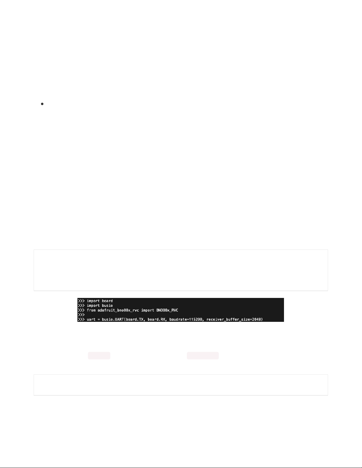
Before continuing make sure your board's lib folder or root filesystem has the adafruit_BNO08x_RVC.mpy file copied
over.
Python Installation of BNO08x RVC Library
Follow the instructions on the Python & CircuitPython page (https://adafru.it/O0b) to set up your Raspberry Pi or other
SBC and once that's done, from your command line run the following command:
sudo pip3 install adafruit-circuitpython-bno08x-rvc
If your default Python is version 3 you may need to run 'pip' instead. Just make sure you aren't trying to use
CircuitPython on Python 2.x, it isn't supported!
CircuitPython & Python Usage
he following code will walk you through a basic test of the UART RVC mode in the Python REPL
To demonstrate the usage of the sensor setup a UART connection and then we'll initialize the sensor and read the
heading and acceleration information from within the board's REPL.
For CircuitPython connect to the board's serial REPL (https://adafru.it/Awz)so you are at the CircuitPython >>> prompt.
For Python, just type `python` or `python3` to enter the REPL
UART Initialization - CircuitPython
If you are using the UART connection with a board (like a Feather) running CircuitPython, create your uart object as
follows:
import board
import busio
from adafruit_bno08x_rvc import BNO08x_RVC
uart = busio.UART(board.TX, board.RX, baudrate=115200, receiver_buffer_size=2048)
UART Initialization - Python
Check how you specific board supports UART and where the port entry is created and named. For the Raspberry Pi,
this is done using the pyserial module and the UART used is /dev/serial0 . Then you create your sensor object as
follows:
import serial
uart = serial.Serial("/dev/serial0", 115200)
© Adafruit Industries
https://learn.adafruit.com/adafruit-9-dof-orientation-imu-fusion-breakout-
bno085
Page 31 of 41
Page 30
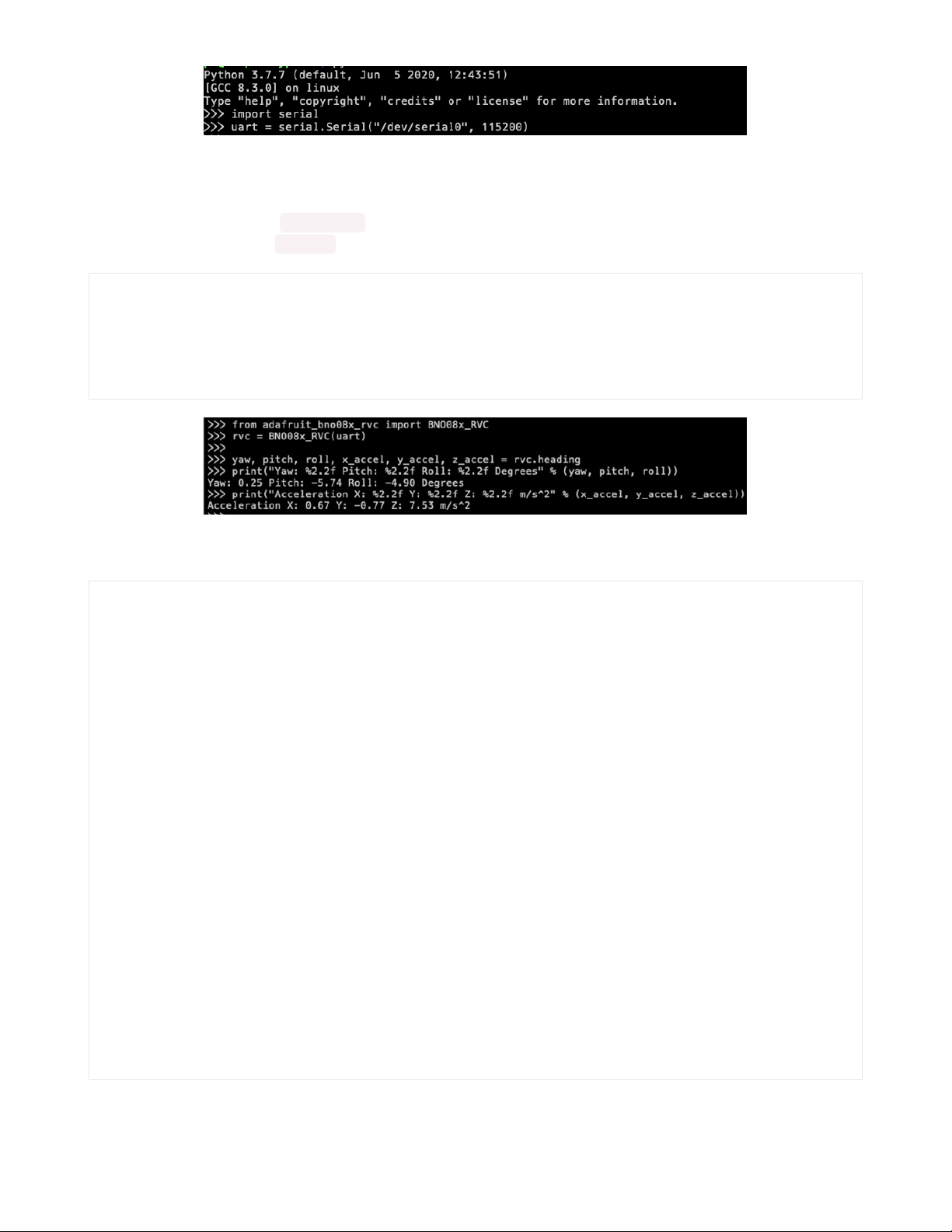
BNO08x_RVC creation and usage
Now you're ready to create a BNO8x_RVC instance with your UART object and use it to read the heading and
acceleration value using the heading property:
from adafruit_bno08x_rvc import BNO08x_RVC
rvc = BNO08x_RVC(uart)
yaw, pitch, roll, x_accel, y_accel, z_accel = rvc.heading
print("Yaw: %2.2f Pitch: %2.2f Roll: %2.2f Degrees" % (yaw, pitch, roll))
print("Acceleration X: %2.2f Y: %2.2f Z: %2.2f m/s^2" % (x_accel, y_accel, z_accel))
Example Code
# SPDX-FileCopyrightText: 2020 Bryan Siepert, written for Adafruit Industries
#
# SPDX-License-Identifier: Unlicense
import time
import board
import busio
uart = busio.UART(board.TX, board.RX, baudrate=115200, receiver_buffer_size=2048)
# uncomment and comment out the above for use with Raspberry Pi
# import serial
# uart = serial.Serial("/dev/serial0", 115200)
# for a USB Serial cable:
# import serial
# uart = serial.Serial("/dev/ttyUSB0", baudrate=115200)
from adafruit_bno08x_rvc import BNO08x_RVC # pylint:disable=wrong-import-position
rvc = BNO08x_RVC(uart)
while True:
yaw, pitch, roll, x_accel, y_accel, z_accel = rvc.heading
print("Yaw: %2.2f Pitch: %2.2f Roll: %2.2f Degrees" % (yaw, pitch, roll))
print("Acceleration X: %2.2f Y: %2.2f Z: %2.2f m/s^2" % (x_accel, y_accel, z_accel))
print("")
time.sleep(0.1)
© Adafruit Industries
https://learn.adafruit.com/adafruit-9-dof-orientation-imu-fusion-breakout-
bno085
Page 32 of 41
Page 31

Python
Docs
Python Docs (https://adafru.it/Nsb)
© Adafruit Industries
https://learn.adafruit.com/adafruit-9-dof-orientation-imu-fusion-breakout-
bno085
Page 33 of 41
Page 32

Python UART RVC
Docs
Python UART RVC Docs (https://adafru.it/NxE)
© Adafruit Industries
https://learn.adafruit.com/adafruit-9-dof-orientation-imu-fusion-breakout-
bno085
Page 34 of 41
Page 33
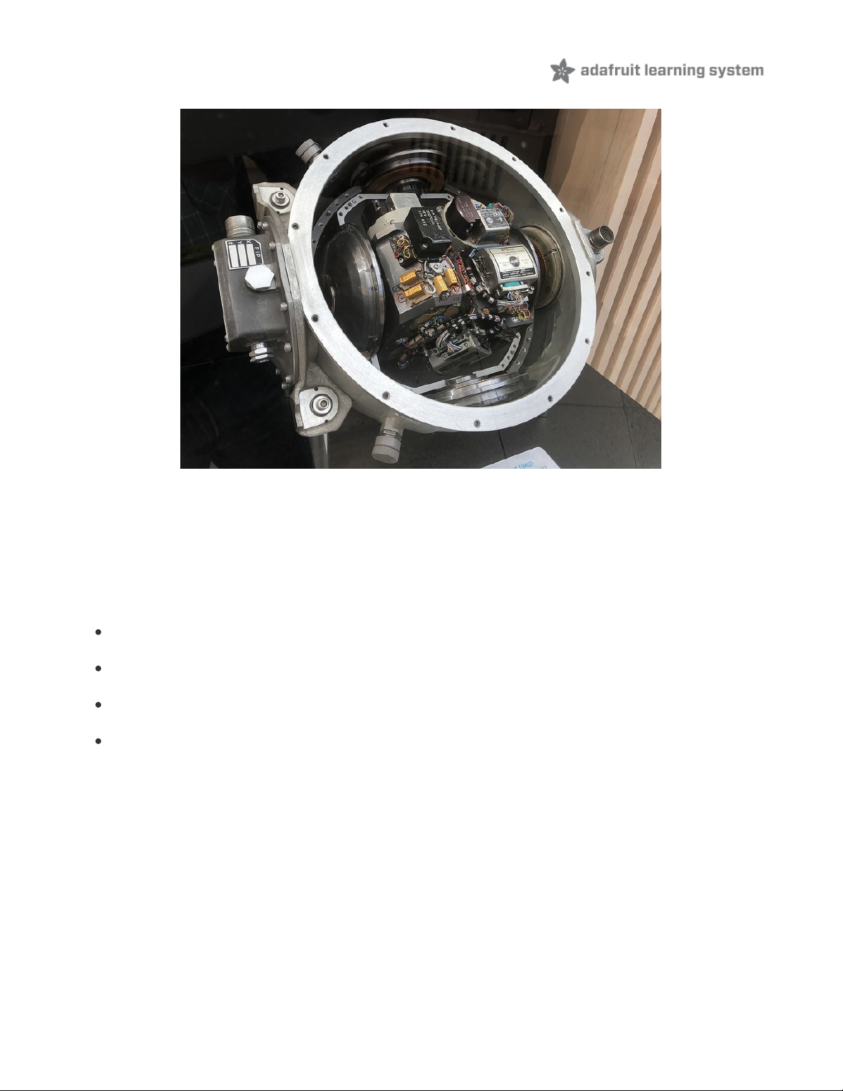
Report Types
The BNO085 offers many different reports of sensor and classification data as listed below. Multiple reports can be
enabled at the same time, allowing you to compare different results or to provide additional data for your application.
Motion Vectors
These reports return calibrated X, Y, and Z axis measurements for the given sensor measurement type.
Acceleration Vector / Accelerometer
Three axes of acceleration from gravity and linear motion, in m/s
Angular Velocity Vector / Gyro
Three axes of rotational speed in radians per second
Magnetic Field Strength Vector / Magnetometer
Three axes of magnetic field sensing in micro Teslas (uT)
Linear Acceleration Vector
Three axes of linear acceleration data with the acceleration from gravity, in m/s^2
2
© Adafruit Industries
https://learn.adafruit.com/adafruit-9-dof-orientation-imu-fusion-breakout-
bno085
Page 35 of 41
Page 34
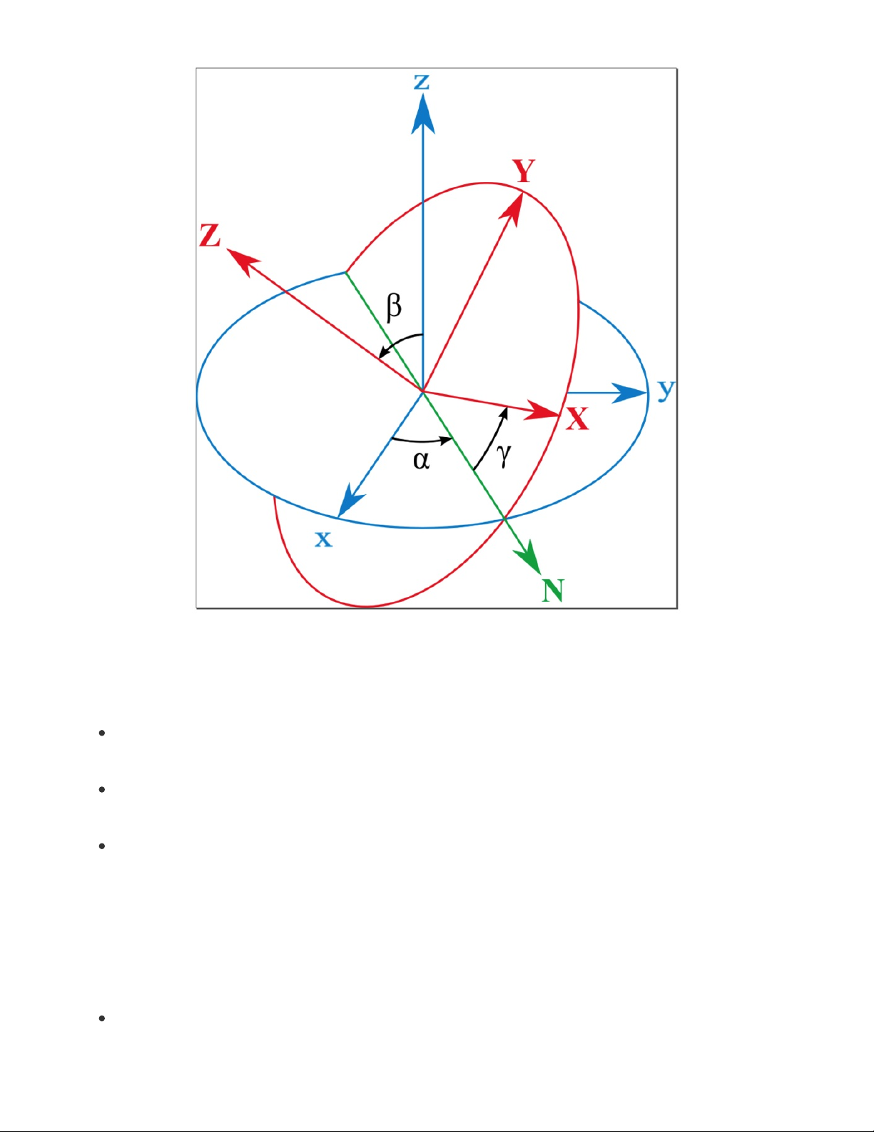
Rotation Vectors
These reports are generated by the BNO085's sensor fusion firmware based on the combination of multiple three-axis
motion vectors and are each optimized for different use cases
Absolute Orientation/ Rotation Vector - Quaternion
Optimized for accuracy and referenced to magnetic north and gravity from accelerometer, gyro, and
magnetometer data. The data is presented as a four point quaternion output for accurate data manipulation
Geomagnetic Rotation Vector - Quaternion
Optimized for low power by fusing the accelerometer and magnetometer only, at the cost of responsiveness and
accuracy
Game Rotation Vector - Quaternion
Optimized for a smoother gaming experience, fused from the accelerometer and gyro without the magnetometer
to avoid sudden jumps in the output from magnetometer based corrections
Classification Reports
Using its sensor fusion products, the BNO085 can attempt to classify and detect different types of motion it measures.
These are pretty neat and work very well when compared similar features found in other 3 or 6-axis motion sensors
Stability Classification
© Adafruit Industries
https://learn.adafruit.com/adafruit-9-dof-orientation-imu-fusion-breakout-
bno085
Page 36 of 41
Page 35
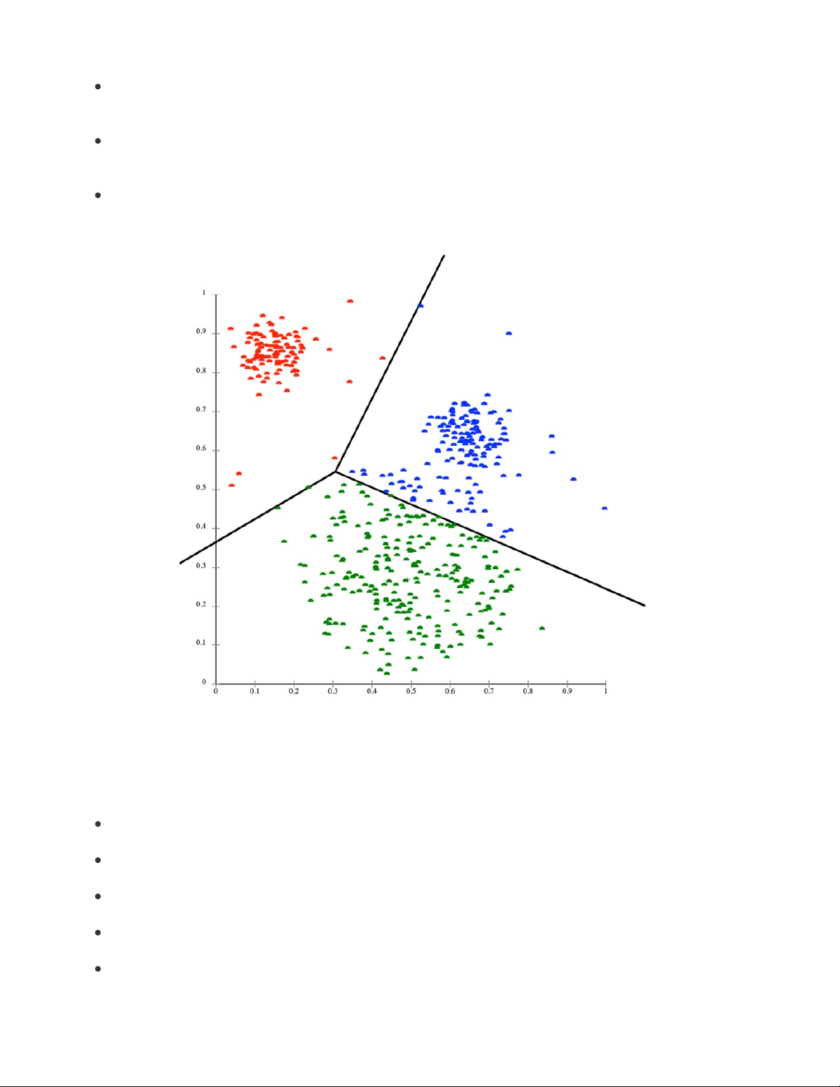
Uses the accelerometer and gyro to classify the detected motion as "On table", "Stable", or "Motion"
Step Counter
Based on the data from the step detector, the sensor tracks the number of steps taken, possibly reclassifying
previous events based on the patterns detected.
Activity Classification
Classifies the detected motion as one of several activity types, providing a most likely classification along with
confidence levels for the most likely and other motion types.
Shake Detector
Detects if the sensor has been shaken
Other Motion Reports
The BNO085 also provides raw ADC readings as well as uncorrected measurements for the accelerometer, gyro, and
magnetometer.
Raw Accelerometer
Unscaled direct ADC readings
Uncalibrated Gyroscope
Angular velocity without bias compensation, with bias separated
Raw Gyroscope
Unscaled direct ADC readings
Uncalibrated Magnetometer
Magnetic field measurements without hard iron offset, offset supplied separately
Raw Magnetometer
© Adafruit Industries
https://learn.adafruit.com/adafruit-9-dof-orientation-imu-fusion-breakout-
bno085
Page 37 of 41
Page 36
Unscaled direct ADC readings
Additional Reports
There are more (less popular) reports that we don't support at this time, a PR to the libraries is welcome for folks who
can implement and test them
Gravity Vector
AR/VR stabilized Rotation Vector
AR/VR stabilized Game rotation vector
Gyro rotation Vector
Gyro rotation Vector Prediction
Significant Motion Detector
Stability Detection
Tap Detector
Step Detector
© Adafruit Industries
https://learn.adafruit.com/adafruit-9-dof-orientation-imu-fusion-breakout-
bno085
Page 38 of 41
Page 37
Downloads
Files
BNO08x Datasheet (https://adafru.it/O0c)
EagleCAD files on GitHub (https://adafru.it/O0d)
Fritzing object in the Adafruit Fritzing Library (https://adafru.it/O0e)
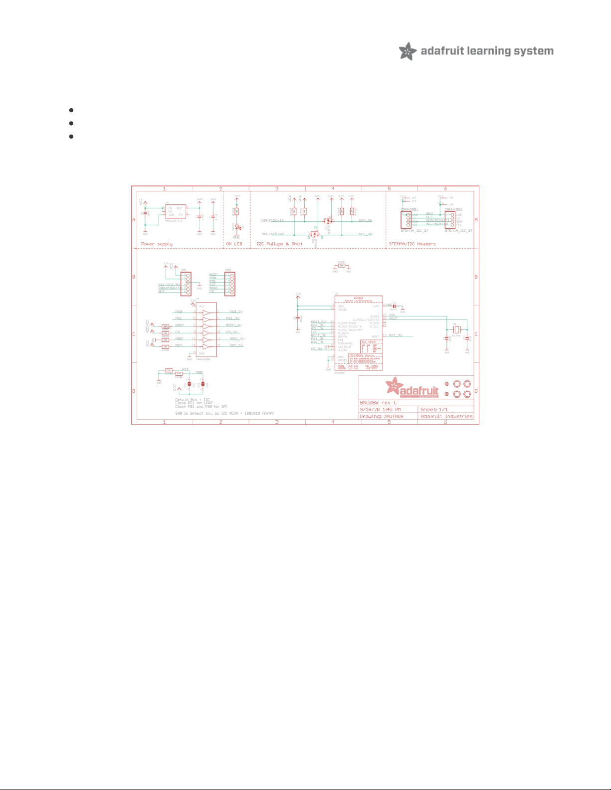
Schematic
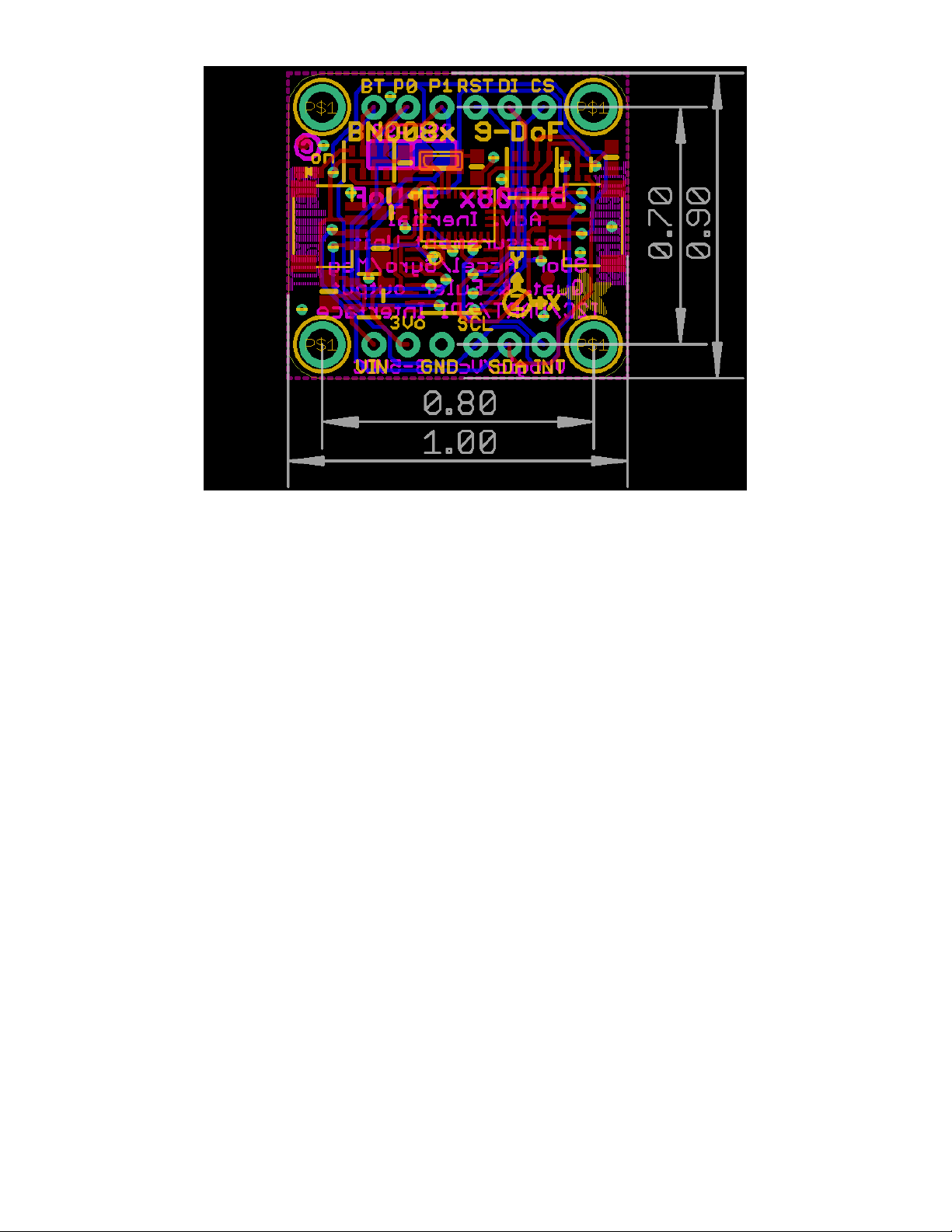
Fab Print
© Adafruit Industries
https://learn.adafruit.com/adafruit-9-dof-orientation-imu-fusion-breakout-
bno085
Page 39 of 41
Page 38
© Adafruit Industries
https://learn.adafruit.com/adafruit-9-dof-orientation-imu-fusion-breakout-
bno085
Page 40 of 41
Page 39

© Adafruit Industries Last Updated: 2020-10-14 11:43:07 AM EDT Page 41 of 41
 Loading...