

Page 1
Adafruit BMP280 Barometric Pressure +
Temperature Sensor Breakout
Created by lady ada
https://learn.adafruit.com/adafruit-bmp280-barometric-pressure-plus-temperature-sensor-
breakout
Last updated on 2021-11-15 06:31:11 PM EST
©Adafruit Industries Page 1 of 27
Page 2

Table of Contents
Overview
Pinouts
• SPI Logic pins:
• Power Pins:
• I2C Logic pins:
Assembly
• Prepare the header strip:
• Add the breakout board:
• And Solder!
Arduino Test
• I2C Wiring
• SPI Wiring
• Download Adafruit_BMP280 library
• Load Demo
• Library Reference
Python & CircuitPython Test
• CircuitPython Microcontroller Wiring
• Python Computer Wiring
• CircuitPython Installation of BMP280 Library
• Python Installation of BMP280 Library
• CircuitPython & Python Usage
3
6
7
6
7
8
8
9
9
10
10
11
12
13
16
17
17
19
21
22
22
Python Docs
F.A.Q.
Downloads
• Documents
• Schematic - STEMMA QT version
• Fab Print - STEMMA QT version
• Schematic - Original version
• Fab Print - Original version
24
24
25
25
25
26
26
27
©Adafruit Industries Page 2 of 27
Page 3

Overview
Bosch has stepped up their game with their new BMP280 sensor, an environmental
sensor with temperature, barometric pressure that is the next generation upgrade to
the BMP085/BMP180/BMP183. This sensor is great for all sorts of weather sensing
and can even be used in both I2C and SPI!
This precision sensor from Bosch is the best low-cost, precision sensing solution for
measuring barometric pressure with ±1 hPa absolute accuracy, and temperature with
±1.0°C accuracy. Because pressure changes with altitude, and the pressure
measurements are so good, you can also use it as an altimeter with ±1 meter
accuracy.
©Adafruit Industries Page 3 of 27
Page 4

The BMP280 is the next-generation of sensors from Bosch, and is the upgrade to the
BMP085/BMP180/BMP183 - with a low altitude noise of 0.25m and the same fast
conversion time. It has the same specifications, but can use either I2C or SPI. For
simple easy wiring, go with I2C. If you want to connect a bunch of sensors without
worrying about I2C address collisions, go with SPI.
Nice sensor right? So we made it easy for you to get right into your next project. The
surface-mount sensor is soldered onto a custom made PCB in theSTEMMA QTform
factor(https://adafru.it/LBQ), making them easy to interface with. TheSTEMMA QT
connectors(https://adafru.it/JqB)on either side are compatible with theSparkFun
Qwiic(https://adafru.it/Fpw)I2C connectors. This allows you to make solderless
©Adafruit Industries Page 4 of 27
Page 5

connections between your development board and the BMP280 or to chain it with a
wide range of other sensors and accessories using acompatible cable(https://
adafru.it/JnB). We’ve of course broken out all the pins to standard headers and added
a voltage regulator and level shifting so allow you to use it with either 3.3V or 5V
systems such as the Metro M4 or Arduino Uno respectively.
We even wrote up a nice tutorial with wiring diagrams, schematics, libraries and
examples to get you running in 10 minutes! Make sure to check the tutorial for
example code for Arduino and CircuitPython, pinouts, assembly, wiring, downloads,
and more!(https://adafru.it/MbA)
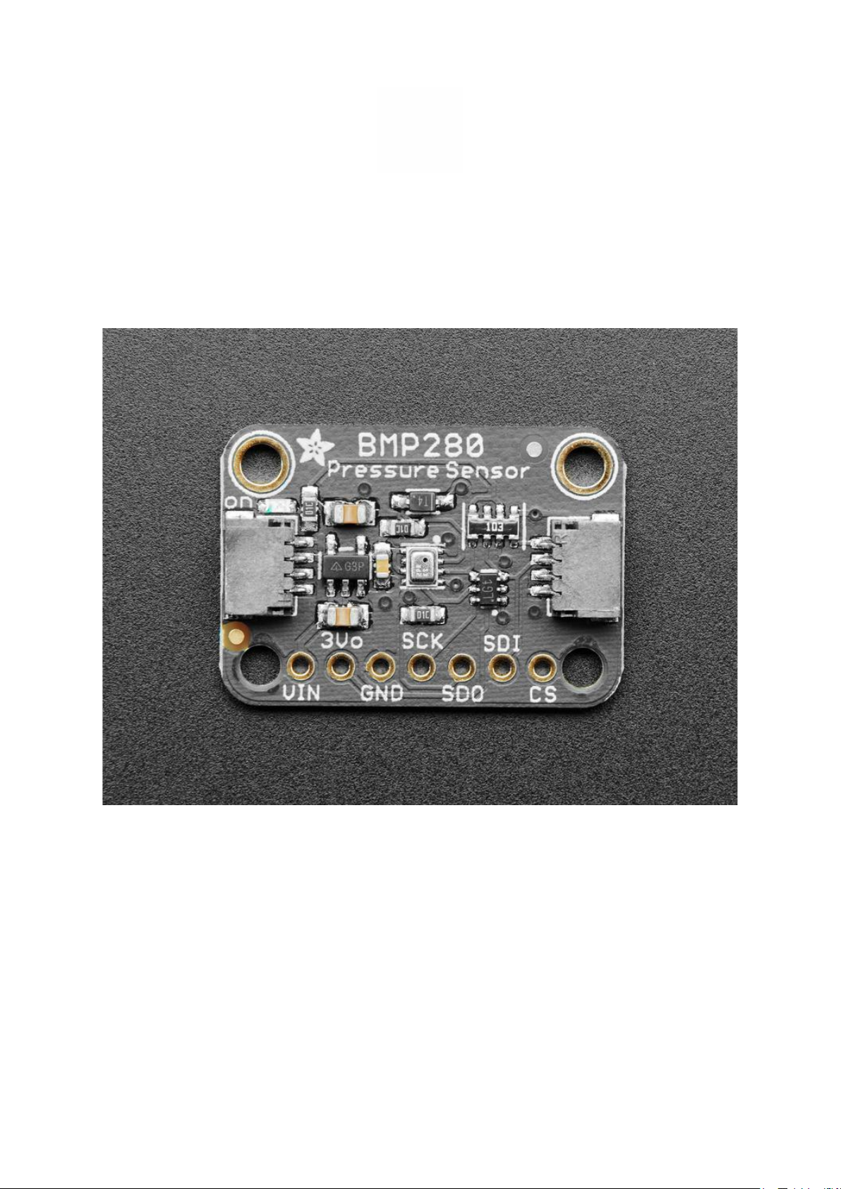
There are two versions of this board - the STEMMA QT version shown above, and
the original header-only version shown below. Code works the same on both!
©Adafruit Industries Page 5 of 27
Page 6

Pinouts
Power Pins:
Vin - this is the power pin. Since the sensor chip uses 3 VDC, we have included
•
a voltage regulator on board that will take 3-5VDC and safely convert it down.
To power the board, give it the same power as the logic level of your
microcontroller - e.g. for a 5V micro like Arduino, use 5V
3Vo - this is the 3.3V output from the voltage regulator, you can grab up to
•
100mA from this if you like
©Adafruit Industries Page 6 of 27
Page 7

GND - common ground for power and logic
•
SPI Logic pins:
All pins going into the breakout have level shifting circuitry to make them 3-5V logic
level safe. Use whatever logic level is on Vin!
SCK - This is the SPI Clock pin, its an input to the chip
•
SDO - this is the Serial Data Out / Microcontroller In Sensor Out pin, for data
•
sent from theBMP280 to your processor
SDI - this is the Serial Data In / Microcontroller Out Sensor Inpin, for data sent
•
from your processor to the BMP280
CS - this is the Chip Select pin, drop it low to start an SPI transaction. Its an input
•
to the chip
If you want to connect multiple BMP280's to one microcontroller, have them share the
SDI, SDO and SCK pins. Then assign each one a unique CS pin.
I2C Logic pins:
SCK - this is also the I2C clock pin (SCL), connect to your microcontroller's I2C
•
clock line.
SDI - this is also the I2C data pin (SDA), connect to your microcontroller's I2C
•
data line.
Leave the other pins disconnected
©Adafruit Industries Page 7 of 27
Page 8

Assembly
The assembly pix use the BME280 but it is identically shaped/sized as the
BMP280
Prepare the header strip:
Cut the strip to length if necessary. It will
be easier to solder if you insert it into a
breadboard - long pins down
©Adafruit Industries Page 8 of 27
Page 9

Add the breakout board:
Place the breakout board over the pins
so that the short pins poke through the
breakout pads
And Solder!
Be sure to solder all pins for reliable
electrical contact.
(For tips on soldering, be sure to check
out our Guide to Excellent
Soldering(https://adafru.it/aTk)).
©Adafruit Industries Page 9 of 27
Page 10

You're done! Check your solder joints
visually and continue onto the next steps
Arduino Test
You can easily wire this breakout to any microcontroller, we'll be using an Arduino. For
another kind of microcontroller, as long as you have 4 available pins it is possible to
'bit-bang SPI' or you can use two I2C pins, but usually those pins are fixed in
hardware. Just check out the library, then port the code.
I2C Wiring
Use this wiring if you want to connect via I2C interface
©Adafruit Industries Page 10 of 27
Page 11

Connect Vin (red wire on STEMMA
•
version) to the power supply, 3-5V
is fine. Use the same voltage that
the microcontroller logic is based
off of. For most Arduinos, that is 5V
Connect GND (black wire on
•
STEMMA version) to common
power/data ground
Connect the SCK (yellow wire on
•
STEMMA version) pin to the I2C
clock SCL pin on your Arduino. On
an UNO & '328 based Arduino, this
is also known as A5, on a Mega it is
also known as digital 21 and on a
Leonardo/Micro, digital 3
Connect the SDI (blue wire on
•
STEMMA version) pin to the I2C
data SDA pin on your Arduino. On
an UNO & '328 based Arduino, this
is also known as A4, on a Mega it is
also known as digital 20 and on a
Leonardo/Micro, digital 2
SPI Wiring
Since this is a SPI-capable sensor, we can use hardware or 'software' SPI. To make
wiring identical on all Arduinos, we'll begin with 'software' SPI. The following pins
should be used:
©Adafruit Industries Page 11 of 27
Page 12

Connect Vin to the power supply,
•
3V or 5V is fine. Use the same
voltage that the microcontroller
logic is based off of. For most
Arduinos, that is 5V
Connect GND to common power/
•
data ground
Connect the SCK pin to Digital #13
•
but any pin can be used later
Connect the SDO pin to Digital #12
•
but any pin can be used later
Connect the SDI pin to Digital #11
•
but any pin can be used later
Connect the CS pin Digital #10 but
•
any pin can be used later
Later on, once we get it working, we can adjust the library to use hardware SPI if you
desire, or change the pins to other
Download Adafruit_BMP280 library
To begin reading sensor data, you will need to install the Adafruit_BMP280 library
(code on our github repository)(https://adafru.it/fIK). It is available from the Arduino
library manager so we recommend using that.
From the IDE open up the library manager...
©Adafruit Industries Page 12 of 27
Page 13

And type in adafruit bmp280 to locate the library. Click Install
You'll also need to install the Adafruit Unified Sensor library
We also have a great tutorial on Arduino library installation at:
http://learn.adafruit.com/adafruit-all-about-arduino-libraries-install-use(https://
adafru.it/aYM)
Load Demo
Open up File->Examples->Adafruit_BMP280->bmp280test and upload to your Arduino
wired up to the sensor
©Adafruit Industries Page 13 of 27
Page 14

Depending on whether you are using I2C or SPI, change the pin names and comment
or uncomment the following lines.
#define BMP_SCK 13
#define BMP_MISO 12
#define BMP_MOSI 11
#define BMP_CS 10
Adafruit_BMP280 bmp; // I2C
//Adafruit_BMP280 bmp(BMP_CS); // hardware SPI
//Adafruit_BMP280 bmp(BMP_CS, BMP_MOSI, BMP_MISO, BMP_SCK);
Once uploaded to your Arduino, open up the serial console at 9600 baud speed to
see data being printed out
©Adafruit Industries Page 14 of 27
Page 15

Temperature is calculated in degrees C, you can convert this to F by using the classic
F = C * 9/5 + 32 equation.
Pressure is returned in the SI units of Pascals. 100 Pascals = 1 hPa = 1 millibar. Often
times barometric pressure is reported in millibar or inches-mercury. For future
reference 1 pascal =0.000295333727 inches of mercury, or 1 inch Hg = 3386.39
Pascal. So if you take the pascal value of say 100734 and divide by 3389.39 you'll get
29.72 inches-Hg.
You can also calculate Altitude. However, you can only really do a good accurate job
of calculating altitude if you know the hPa pressure at sea level for your location and
day! The sensor is quite precise but if you do not have the data updated for the
current day then it can be difficult to get more accurate than 10 meters.
©Adafruit Industries Page 15 of 27
Page 16

Library Reference
You can start out by creating a BMP280 object with either software SPI (where all four
pins can be any I/O) using
Adafruit_BMP280 bmp(BMP_CS, BMP_MOSI, BMP_MISO, BMP_SCK);
Or you can use hardware SPI. With hardware SPI you must use the hardware SPI pins
for your Arduino - and each arduino type has different pins! Check the SPI reference
to see what pins to use.(https://adafru.it/d5h)
In this case, you can use any CS pin, but the other three pins are fixed
Adafruit_BMP280 bmp(BMP_CS); // hardware SPI
or I2C using the default I2C bus, no pins are assigned
Adafruit_BMP280 bmp; // I2C
Once started, you can initialize the sensor with
if (!bmp.begin()) {
Serial.println("Could not find a valid BMP280 sensor, check wiring!");
while (1);
}
begin() will return True if the sensor was found, and False if not. If you get a False
value back, check your wiring!
Reading temperature and pressure is easy, just call:
bmp.readTemperature()
bmp.readPressure()
Temperature is always a floating point, in Centigrade. Pressure is a 32 bit integer with
the pressure in Pascals. You may need to convert to a different value to match it with
your weather report.
It's also possible to turn the BMP280 into an altimeter. If you know the pressure at sea
level, the library can calculate the current barometric pressure into altitude
©Adafruit Industries Page 16 of 27
Page 17

Python & CircuitPython Test
It's easy to use the BMP280 sensor with CircuitPython and theAdafruit CircuitPython
BMP280(https://adafru.it/C0x)module. This module allows you to easily write Python
code that reads the temperature and pressure from the sensor.
You can use this sensor with any CircuitPython microcontroller board or with a
computer that has GPIO and Pythonthanks to Adafruit_Blinka, our CircuitPython-for-
Python compatibility library(https://adafru.it/BSN).
CircuitPython Microcontroller Wiring
First wire up a BMP280 to your board exactly as shown on the previous pages for
Arduino. You can use either I2C or SPI wiring, although it's recommended to use I2C
for simplicity. Here's an example of wiring a Feather to the sensor with I2C:
©Adafruit Industries Page 17 of 27
Page 18

Board 3Vtosensor VIN (red wire on
•
STEMMA version)
Board GNDtosensor GND (black
•
wire on STEMMA version)
Board SCLtosensor SCK (yellow
•
wire on STEMMA version)
Board SDAtosensor SDI (blue wire
•
on STEMMA version)
And an example of a Feather M0 wired with hardware SPI:
©Adafruit Industries Page 18 of 27
Page 19

Board 3Vtosensor VIN
•
Board GNDtosensor GND
•
Board SCKtosensor SCK
•
BoardMOSItosensor SDI
•
Board MISOtosensor SDO
•
Board D5tosensor CS(or use any
•
other free digital I/O pin)
Python Computer Wiring
Since there'sdozensof Linux computers/boards you can use we will show wiring for
Raspberry Pi. For other platforms,please visit the guide for CircuitPython on Linux to
see whether your platform is supported(https://adafru.it/BSN).
Here's the Raspberry Pi wired with I2C:
©Adafruit Industries Page 19 of 27
Page 20

Pi 3V3tosensor VIN (red wire on
•
STEMMA version)
Pi GNDtosensor GND (black wire
•
on STEMMA version)
Pi SCLtosensor SCK (yellow wire
•
on STEMMA version)
Pi SDAtosensor SDI (blue wire on
•
STEMMA version)
And an example on the Raspberry Pi 3 Model B wired with SPI:
©Adafruit Industries Page 20 of 27
Page 21

Pi 3V3tosensor VIN
•
Pi GNDtosensor GND
•
Pi MOSItosensor SDI
•
Pi MISOtosensor SDO
•
Pi SCLKtosensor SCK
•
Pi #5tosensor CS(or use any other
•
free GPIO pin)
CircuitPython Installation of BMP280 Library
You'll need to install theAdafruit CircuitPython BMP280(https://adafru.it/C0x)library
on your CircuitPython board.
First make sure you are running thelatest version of Adafruit CircuitPython(https://
adafru.it/Amd)for your board.
Next you'll need to install the necessary librariesto use the hardware--carefully follow
the steps to find and install these libraries fromAdafruit's CircuitPython library bundle
(https://adafru.it/uap). Our CircuitPython starter guide has a great page on how to
install the library bundle(https://adafru.it/ABU).
For non-express boards like the Trinket M0 or Gemma M0, you'll need to manually
install the necessary libraries from the bundle:
adafruit_bmp280.mpy
•
©Adafruit Industries Page 21 of 27
Page 22

adafruit_bus_device
•
Before continuing make sure your board's lib folder or root filesystem has theadafrui
t_bmp280.mpy, and adafruit_bus_devicefiles and folderscopied over.
Nextconnect to the board's serial REPL(https://adafru.it/Awz)so you are at the
CircuitPython>>>prompt.
Python Installation of BMP280 Library
You'll need to install the Adafruit_Blinka library that provides the CircuitPython
support in Python. This may also require enabling I2C on your platform and verifying
you are running Python 3.Since each platform is a little different, and Linux changes
often, please visit the CircuitPython on Linux guide to get your computer ready(https
://adafru.it/BSN)!
Once that's done, from your command line run the following command:
sudo pip3 install adafruit-circuitpython-bmp280
•
If your default Python is version 3 you may need to run 'pip' instead. Just make sure
you aren't trying to use CircuitPython on Python 2.x, it isn't supported!
CircuitPython & Python Usage
To demonstrate the usage of the sensor we'll initialize it and read the temperature,
humidity, and more from the board's Python REPL.
If you're using an I2C connection run the following code to import the necessary
modules and initialize the I2C connection with the sensor:
import board
import adafruit_bmp280
i2c = board.I2C()
sensor = adafruit_bmp280.Adafruit_BMP280_I2C(i2c)
Or if you're using a SPI connection run this code instead to setup the SPI connection
and sensor:
©Adafruit Industries Page 22 of 27
Page 23

import board
import digitalio
import adafruit_bmp280
spi = board.SPI()
cs = digitalio.DigitalInOut(board.D5)
sensor = adafruit_bmp280.Adafruit_BMP280_SPI(spi, cs)
Now you're ready to read values from the sensor using any of these properties:
temperature- The sensor temperature in degrees Celsius.
•
pressure- The pressure in hPa.
•
altitude- The altitude in meters.
•
For example to print temperature and pressure:
print('Temperature: {} degrees C'.format(sensor.temperature))
print('Pressure: {}hPa'.format(sensor.pressure))
For altitude you'll want to set the pressure at sea level for your location to get the
most accurate measure (remember these sensors can only infer altitude based on
pressure and need a set calibration point). Look at your local weather report for a
pressure at sea level reading and set theseaLevelhPAproperty:
sensor.sea_level_pressure = 1013.25
Then read the altitude property for a more accurate altitude reading (but remember
this altitude will fluctuate based on atmospheric pressure changes!):
print('Altitude: {} meters'.format(sensor.altitude))
That's all there is to using the BMP280 sensor with CircuitPython!
Here's a starting example that will print out the temperature, pressure and altitude
every 2 seconds:
©Adafruit Industries Page 23 of 27
Page 24

# SPDX-FileCopyrightText: 2021 ladyada for Adafruit Industries
# SPDX-License-Identifier: MIT
"""Simpletest Example that shows how to get temperature,
pressure, and altitude readings from a BMP280"""
import time
import board
# import digitalio # For use with SPI
import adafruit_bmp280
# Create sensor object, communicating over the board's default I2C bus
i2c = board.I2C() # uses board.SCL and board.SDA
bmp280 = adafruit_bmp280.Adafruit_BMP280_I2C(i2c)
# OR Create sensor object, communicating over the board's default SPI bus
# spi = board.SPI()
# bmp_cs = digitalio.DigitalInOut(board.D10)
# bmp280 = adafruit_bmp280.Adafruit_BMP280_SPI(spi, bmp_cs)
# change this to match the location's pressure (hPa) at sea level
bmp280.sea_level_pressure = 1013.25
while True:
print("\nTemperature: %0.1f C" % bmp280.temperature)
print("Pressure: %0.1f hPa" % bmp280.pressure)
print("Altitude = %0.2f meters" % bmp280.altitude)
time.sleep(2)
Python Docs
Python Docs(https://adafru.it/C0B)
F.A.Q.
How come the altitude calculation is wrong? Is my sensor broken?
No, your sensor is likely just fine. The altitude calculation depends on knowing the
barometric pressure at sea level
If you do not set the correct sea level pressure for your location FOR THE
CURRENT DAY it will not be able to calculate the altitude accurately
Barometric pressure at sea level changes daily based on the weather!
If I have long delays between reads, the first data read seems wrong?
The BMx280 'saves' the last reading in memory for you to query. Just read twice in
a row and toss out the first reading!
©Adafruit Industries Page 24 of 27
Page 25

Downloads
Documents
Datasheet for the BMP280 sensor used in the breakout(https://adafru.it/fIO)
•
Arduino BMP280 Driver(https://adafru.it/fIK)
•
Fritzing object in the Adafruit Fritzing Library(https://adafru.it/Mbx)
•
EagleCAD PCB files on GitHub(https://adafru.it/rDq)
•
Schematic - STEMMA QT version
©Adafruit Industries Page 25 of 27
Page 26

Fab Print - STEMMA QT version
Schematic - Original version
Click to enlarge. BMP280 shares the same package & pinout as the BME280 so the
schematic is the same
©Adafruit Industries Page 26 of 27
Page 27

Fab Print - Original version
In inches. BMP280 shares the same package & pinout as the BME280 so the layout is
the same
©Adafruit Industries Page 27 of 27
 Loading...