

Page 1
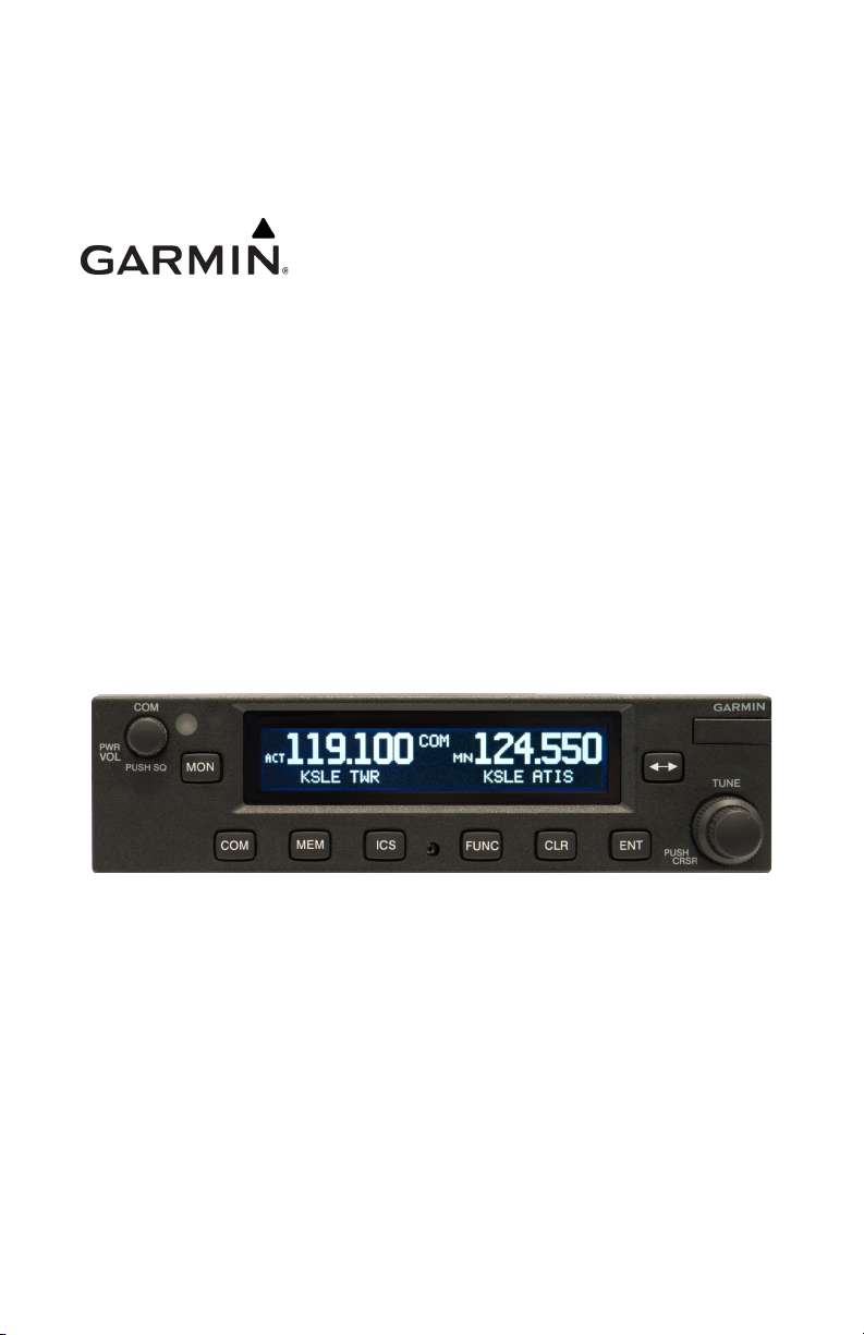
GTR 225/225A/225B
Pilot's Guide
Page 2

COPYRIGHT & TRADEMARKS
© 2012-2020 Garmin Ltd. or its subsidiaries. All rights reserved.
Except as expressly provided herein, no part of this manual may be reproduced,
copied, transmitted, disseminated, downloaded or stored in any storage medium,
for any purpose without the express written permission of Garmin. Garmin hereby
grants permission to download a single copy of this manual and of any revision to
this manual onto a hard drive or other electronic storage medium to be viewed for
personal use, provided that such electronic or printed copy of this manual or revision
must contain the complete text of this copyright notice and provided further that
any unauthorized commercial distribution of this manual or any revision hereto is
strictly prohibited.
Garmin® is a registered trademarks of Garmin Ltd. or its subsidiaries. These
trademarks may not be used without the express permission of Garmin.
SOFTWARE VERSION
This manual reflects the operation of System Software version 2.10, or later. Some
differences in operation may be observed when comparing the information in this
manual to later software versions.
INFORMATION & SUPPORT
For information regarding the Aviation Limited Warranty, refer to Garmin’s website.
For aviation product support, visit flyGarmin.com
.
October 2020 Printed in the U.S.A.
Page 3
Warnings, Cautions, and Notes
WARNING
CAUTION
CAUTION
NOTE
NOTE
NOTE
NOTE
FOR SAFETY REASONS, GTR 225 OPERATIONAL PROCEDURES MUST BE LEARNED ON
THE GROUND.
THE GARMIN GTR 225 DOES NOT CONTAIN ANY USER-SERVICEABLE PARTS.
REPAIRS SHOULD ONLY BE MADE BY AN AUTHORIZED GARMIN SERVICE
CENTER. UNAUTHORIZED REPAIRS OR MODIFICATIONS COULD VOID BOTH
THE WARRANTY AND THE PILOT’S AUTHORITY TO OPERATE THIS DEVICE
UNDER FAA/FCC REGULATIONS.
THE GTR 225 USES A DISPLAY COATED WITH A SPECIAL ANTI-REFLECTIVE
COATING THAT IS VERY SENSITIVE TO SKIN OILS, WAXES, AND ABRASIVE
CLEANERS. CLEANERS CONTAINING AMMONIA WILL HARM THE
ANTI-REFLECTIVE COATING. IT IS VERY IMPORTANT TO CLEAN THE DISPLAY
USING A CLEAN, LINT-FREE CLOTH AND AN EYEGLASS LENS CLEANER THAT
IS SPECIFIED AS SAFE FOR ANTI-REFLECTIVE COATINGS.
Do not use outdated database information. Databases used in the system
must be updated regularly in order to ensure that the information remains
current. Pilots using an outdated database do so entirely at their own risk.
Garmin recommends that if flying in a region with 8.33 kHz COM channel
spacing, the radio should remain in 8.33 kHz mode. This will prevent the loss
of stored user and recent frequencies.
All visual depictions contained within this document, including screen images
of the GTR 225 bezel and displays, are subject to change and may not reflect
the most current GTR 225 software. Depictions of equipment may differ
slightly from the actual equipment.
This device complies with part 15 of the FCC Rules. Operation is subject to
the following two conditions: (1) this device may not cause harmful
interference, and (2) this device must accept any interference received,
including interference that may cause undesired operation.
190-01182-00 Rev. D Garmin GTR 225/225A/225B Pilot’s Guide i
Page 4

Warnings, Cautions, and Notes
NOTE
NOTE
NOTE
NOTE: This device complies with Part
15 of the FCC limits for Class B
digital devices. This equipment
generates, uses, and can radiate
radio frequency energy and, if not
installed and used in accordance
with the instructions, may cause
harmful interference to radio
communications. Furthermore, there
is no guarantee that interference will
not occur in a particular installation.
If this equipment causes harmful
interference, the user is encouraged
to try to correct the interference by
relocating the equipment or
connecting the equipment to a
different circuit other than the
affected equipment. Consult an
authorized dealer or other qualified
avionics technician for additional
assistance if these remedies do not
correct the problem.
Operation of this device is subject to
the following conditions: (1) This
device may not cause harmful
interference. (2) This device must
accept any interference received,
including interference that may
cause undesired operation.
To obtain accessories for your unit,
please contact your Garmin dealer.
The display surface is coated with
a special anti-reflective material,
which is very sensitive to skin oils,
waxes, and abrasive cleaners. It is
very important to clean the display
using an eyeglass lens cleaner
which is specified as safe for
anti-reflective coatings and a
clean, lint-free cloth.
This product, its packaging, and its components contain chemicals known to
the State of California to cause cancer, birth defects, or reproductive harm.
This notice is being provided in accordance with California’s Proposition 65.
If you have any questions or would like additional information, please refer
to our website at www.garmin.com/prop65.
Canadian installations: In accordance with Canadian Radio Specifications
Standard 102 (RSS 102), RF field strength exposure to persons from an
antenna connected to this device should be limited to 60 V/m for controlled
environment and 28 V/m for uncontrolled environment.
The COM transceiver antenna(s) of the equipment mount along the fuselage
and are accessible only to aircraft maintenance personnel.
ii Garmin GTR 225/225A/225B Pilot’s Guide 190-01182-00 Rev. D
Page 5

Warnings, Cautions, and Notes
Product Registration and Support
Help us better support you by completing your online registration today! Have the
serial number of your product handy and connect to the Garmin website
(www.garmin.com
Registration link on the Home page. Also, be sure to record your serial number in the
space provided.
For aviation product support, visit flyGarmin.com.
or https://fly.garmin.com/fly-garmin). Look for the Product
Record of Revision
PART
NUMBER
190-01182-00
REVISION DATE CHANGE DESCRIPTION
A 11/19/12 Initial Release.
B 03/30/15 Added v2.10 functionality.
C 10/05/20
D 10/21/20
Added COM transceiver note and
removed support phone numbers.
Updated images on page 3-14.
190-01182-00 Rev. D Garmin GTR 225/225A/225B Pilot’s Guide iii
Page 6

INTENTIONALLY LEFT BLANK
iv Garmin GTR 225/225A/225B Pilot’s Guide 190-01182-00 Rev. D
Page 7

Table of Contents
1 GETTING STARTED ............................................................................................................ 1-1
1.1 Product Description ................................................................................... 1-1
1.2 Pilot Controls ............................................................................................ 1-2
1.3 USB Port ................................................................................................... 1-3
2 COM RADIO BASIC OPERATION ................................................................................ 2-1
2.1 Selecting a COM Frequency ...................................................................... 2-1
2.2 Monitoring the Standby COM Channel ..................................................... 2-2
2.3 Saving a COM Channel ............................................................................. 2-2
2.4 COM Database Look-Up ........................................................................... 2-4
2.5 Emergency Channel .................................................................................. 2-5
2.6 Stuck Mic .................................................................................................. 2-5
2.7 Frequency Database Reverse Look-Up ....................................................... 2-5
2.8 Remote Frequency Selection Control ......................................................... 2-6
3 FUNCTIONS ........................................................................................................................... 3-1
3.1 Functions .................................................................................................. 3-1
3.2 COM Frequencies ..................................................................................... 3-2
3.2.1 Recent COM Frequencies ................................................................... 3-2
3.2.2 COM User Frequencies ....................................................................... 3-2
3.2.3 COM Database Frequencies ................................................................ 3-4
3.2.4 COM Nearest Airports (APT) ............................................................... 3-5
3.2.5 COM Nearest Area Control Center (ACC) Frequencies ........................ 3-5
3.2.6 COM Nearest Flight Service Station (FSS) Frequencies ......................... 3-6
3.2.7 COM Nearest Weather (WX) Frequencies ........................................... 3-6
3.3 ICS Configuration ..................................................................................... 3-7
3.3.1 Adjust Intercom .................................................................................. 3-7
3.3.2 AUX Audio ......................................................................................... 3-8
3.3.3 Intercom On/Off ................................................................................. 3-8
3.3.4 Speaker On/Off .................................................................................. 3-9
3.4 System Configuration ............................................................................. 3-10
3.4.1 COM Spacing ................................................................................... 3-10
3.4.2 COM Sidetone (Software v2.10 or later) ........................................... 3-11
3.4.3 Display Brightness ............................................................................ 3-12
3.4.4 Display Contrast ............................................................................... 3-12
3.4.5 Database Info ................................................................................... 3-13
3.4.6 Load Database ................................................................................. 3-13
3.4.7 Software Version .............................................................................. 3-14
3.4.8 Serial Number .................................................................................. 3-14
3.5 Timers ..................................................................................................... 3-15
3.5.1 Setting Up the Count Down Timer ................................................... 3-15
3.5.2 Setting Up the Count Up Timer ........................................................ 3-15
3.5.3 Viewing Timers in the COM Display .................................................. 3-16
4 DATABASE INFORMATION ............................................................................................ 4-1
4.1 Downloading the Frequency Database ...................................................... 4-1
4.2 Updating the GTR 225 Frequency Database .............................................. 4-1
5 TROUBLESHOOTING ........................................................................................................ 5-1
5.1 Messages .................................................................................................. 5-3
190-01182-00 Rev. D Garmin GTR 225/225A/225B Pilot’s Guide v
Page 8

INTENTIONALLY LEFT BLANK
vi Garmin GTR 225/225A/225B Pilot’s Guide 190-01182-00 Rev. D
Page 9
Getting Started
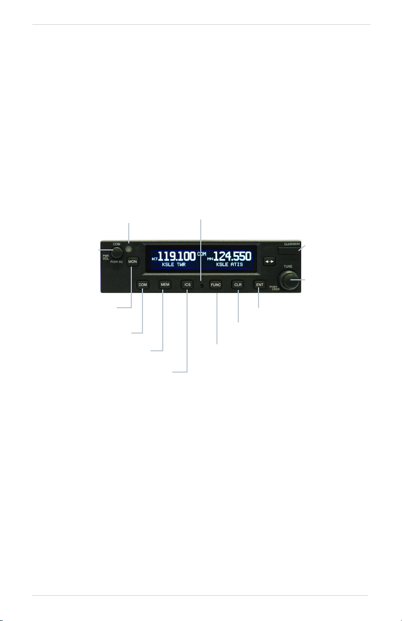
Photo Sensor
Locking
Screw
USB Port
Power On/Off,
COM Volume,
Squelch
On/Off
Frequency
Monitor Key
Press To Return To
COM Display
View Recent or User Freq
Intercom Function
Function Selection
Clear Data Key
Enter Key
Outer and
Inner Knobs
(Frequency
Adjust)
1 Getting Started
1.1 Product Description
The GTR 225 COM Radio series provides a powerful VHF communications
transceiver. In addition to the traditional COM features, the GTR 225 series
incorporates workload-reducing functions.
The GTR 225 series monitors the standby COM frequencies and stores the user’s
most-used frequencies. The GTR 225 (10 watt) COM radio operates in the aviation
voice band, from 118.000 to 136.975 MHz, in 25 kHz steps (default). For European
operations, configuration for 8.33 kHz steps is provided with the GTR 225A (10 watt)
and GTR 225B (16 watt).
GTR 225 Front Panel Description
190-01182-00 Rev. D Garmin GTR 225/225A/225B Pilot’s Guide 1-1
Page 10
Getting Started
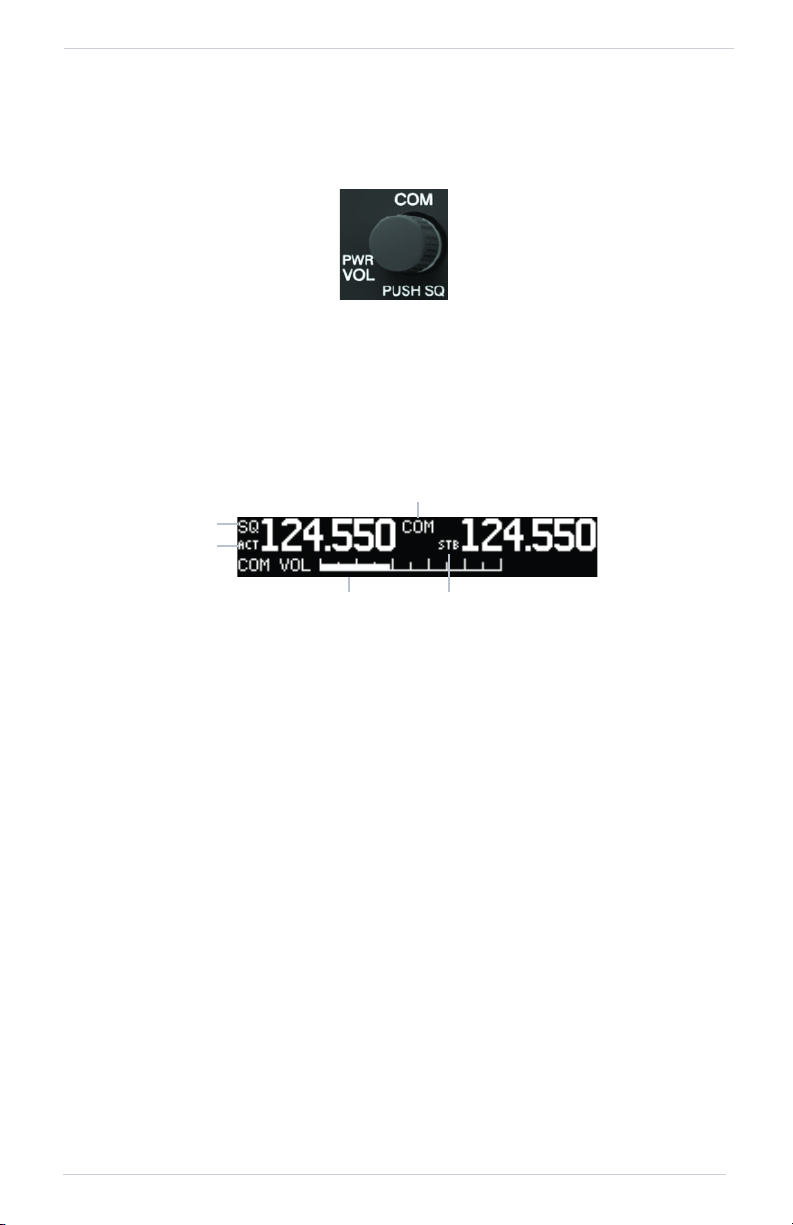
Squelch, TX, or RX
Annunciator
Active Frequency
Annunciator
COM Volume Bar Graph
Standby Frequency
Annunciator
COM Mode
Annunciator
1.2 Pilot Controls
The GTR 225 controls are designed to simplify systems operation, minimize
workload, and reduce time required to access functionality. Controls are comprised
of dual knobs for frequency tuning, COM volume/squelch knob, and bezel keys.
Power/COM Volume/Squelch Knob
The Power/COM Volume/Squelch knob located in the top left corner of the bezel
controls audio volume for the COM radio. To power on, turn the knob clockwise
past detent. Turn the knob counterclockwise to power off. When the COM radio is
active, press the Power/COM Volume/Squelch knob to toggle automatic squelch
control On/Off for the COM radio.
The COM radio has an automatic squelch to reject many localized noise sources. You
may override the squelch function by pressing the Power/COM Volume/Squelch
knob. This facilitates listening to a distant station or setting the desired volume level.
To override the automatic squelch, press the Power/COM Volume/Squelch knob
momentarily. Press the Power/COM Volume/Squelch knob again to return to
automatic squelch operation. When the automatic squelch is overridden, an “SQ”
indicator appears in the upper left corner of the display, left of the active COM
frequency window.
1-2 Garmin GTR 225/225A/225B Pilot’s Guide 190-01182-00 Rev. D
COM Volume and Squelch Display
Page 11
Getting Started
NOTE
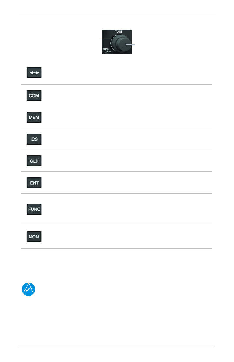
Outer Knob
Inner Knob
The outer right and inner right knobs are used for tuning frequencies and data entry.
To switch between the active (left-most) and standby (right-most)
frequency press and release the FLIP/FLOP key. Switching between
COM frequencies is disabled when transmitting.
To return to the COM radio mode press the COM key.
To recall and toggle between the COM Recent and User Frequency lists
press the MEM key.
To toggle display of the ICS settings for Intercom On/Off, AUX Audio,
or the Intercom settings press the ICS key.
To erase information, cancel entries, and reset timers press the CLR
key.
To save selected values, to confirm a prompt, or to save the standby
frequency press the ENT key.
The FUNC (Function) key accesses function categories for the COM
Radio, ICS Configuration, System Configuration, and Timer. Pressing
the FUNC key once displays the Function mode. Pressing the FUNC key
a second time exits the Function mode.
The MON (Monitor) key engages the monitor function. The standby
frequency can be monitored while still listening to the active
frequency.
1.3 USB Port
The USB port is used to update the frequency database in the GTR 225.
For updating the databases, Garmin recommends the use of a USB 2.0 compatible
flash drive. The flash drive must be formatted as FAT32.
190-01182-00 Rev. D Garmin GTR 225/225A/225B Pilot’s Guide 1-3
Page 12

INTENTIONALLY LEFT BLANK
1-4 Garmin GTR 225/225A/225B Pilot’s Guide 190-01182-00 Rev. D
Page 13

COM Radio Basic Operation
Identifier and Type Shown For
The Selected Frequency
Asterisk Indicates Multiple Types
Exist For The Selected Frequency
2COM Radio Basic
Operation
2.1 Selecting a COM Frequency
New frequencies are first selected as a standby frequency and then toggled to the
active side with the FLIP/FLOP key. While viewing the standby frequency display, use
the outer and inner knobs on the right side of the GTR 225 to select the desired
frequency.
COM Frequency Selection
1. Press COM, if necessary, to reach the COM radio function. The COM
annunciator on the top line of the display will show.
2. Turn the outer knob to change the values in one MHz increments. The MHz
selection range is between 118 and 136 in one MHz steps.
3. Turn the inner knob to change the values in 25 kHz or 8.33 kHz increments.
The kHz selection range is between 000 and 975 kHz in 25 kHz steps or 000
and 990 kHz in 8.33 kHz steps.
4. Turn the outer and inner knobs clockwise to increase and counterclockwise to
decrease the frequency values. Standby frequency selection is not inhibited
during transmit.
5. When connected to a position source, the nearest station identifier will be
shown for the selected frequency. Frequencies with multiple types will have
an asterisk next to the identifier.
6. Press and release the FLIP/FLOP key to toggle the standby frequency to the
active frequency.
190-01182-00 Rev. D Garmin GTR 225/225A/225B Pilot’s Guide 2-1
Page 14
COM Radio Basic Operation
NOTE
Monitor
Annunciation
Monitored
Standby
Frequency
Number of
Frequencies Saved
2.2 Monitoring the Standby COM Channel
COM Frequency Monitor Annunciation
The Frequency Monitoring function allows you to monitor the standby frequency for
activity, while listening to the active frequency.
Press the MON key in the COM function to listen to the standby frequency. A small
“MN” will replace the “STB” to the left of the standby frequency.
When the active frequency receives a signal, the unit will switch automatically to the
active frequency. The active frequency quality is not affected. The Frequency Monitor
function is turned off by pressing the MON key again.
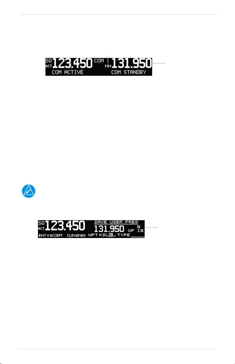
2.3 Saving a COM Channel
The current standby frequency may be saved into the COM User Frequency database
from the COM display or the COM User Function. The COM User Frequency
database can hold up to fifteen frequencies.
When switching from 8.33 kHz to 25 kHz mode, any 8.33 kHz-specific user
frequencies will be deleted from the user frequency list. This only affects the user
frequencies within the 8.33 kHz spectrum.
COM User Frequency Name Selection
1. Press ENT.
2. Turn the inner knob to select characters.
3. Turn the outer knob to move the cursor.
4. After selecting characters, press ENT.
5. Turn the outer knob to select the waypoint type.
6. Turn the inner knob to select the type from the list.
7. Press ENT to save displayed value.
Press CLR to cancel the changes.
2-2 Garmin GTR 225/225A/225B Pilot’s Guide 190-01182-00 Rev. D
Page 15

COM Radio Basic Operation
Waypoint Type
COM User Frequency Type Selection
COM Frequency Type List
FREQUENCY TYPE SYMBOL DESCRIPTION
TWR Tower
GND Ground
ATIS Automatic Terminal Information Service
AWS Automated Weather Observing System
ATF Aerodrome Traffic Frequency
ARR Arrival
APPR Approach
DEP Departure
CLR Clearance
CTAF Common Traffic Advisory Frequency
FSS Flight Service Station
RFS Remote Flight Service Station
MF Mandatory Frequency
UNI
Blank
190-01182-00 Rev. D Garmin GTR 225/225A/225B Pilot’s Guide 2-3
Unicom
None
Page 16
COM Radio Basic Operation
Identifier Field
Character
Selected Identifier
Turn Inner Knob to
Select Frequency Type
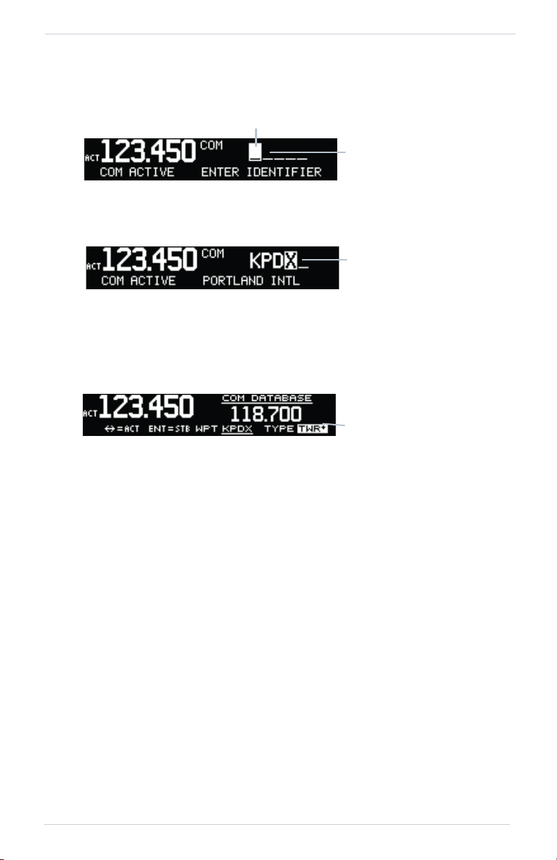
2.4 COM Database Look-Up
1. Press the inner knob from the COM display to activate the database look-up
function.
Database Identifier Active for Selection
2. Turn the inner knob to select characters and turn the outer knob to move the
cursor.
Database Identifier Selection
3. After selecting characters, press ENT.
4. Turn the inner knob to scroll through the list of waypoint types. Waypoint
types with a “+” sign will have more frequencies for the same type. After
selection, the selected waypoint and type will be stored for 30 minutes.
Database Frequency Type Selection
5. Press ENT to copy the frequency into the standby frequency location.
6. The nearest station identifier will show for the selected frequency if
connected to a GPS position source.
7. Press and release the FLIP/FLOP key to swap the active and standby
frequencies.
2-4 Garmin GTR 225/225A/225B Pilot’s Guide 190-01182-00 Rev. D
Page 17

COM Radio Basic Operation
NOTE
NOTE
Airport Identifier Shown for
Frequencies In Database
2.5 Emergency Channel
Press and hold the FLIP/FLOP key or the COM Remote Transfer (COM RMT XFR) key
for approximately two seconds. The Emergency Channel will be inserted into the
active frequency position and the previous active Frequency will become the standby
frequency.
Emergency Channel
Pressing and holding the COM Remote Transfer (COM RMT XFR) key for
approximately two seconds, on units so configured, will lock the COM board,
preventing further changes in COM frequency until the COM board is unlocked, by
pressing the COM Remote Transfer key again for two seconds. The following
message will notify the pilot that the COM board has been locked: “COM LOCKED
TO 121.5 MHZ. HOLD REMOTE COM TRANSFER KEY TO EXIT.”
Under some circumstances if the COM system loses communication with the main
system, the radio will automatically tune to 121.50 MHz for transmit and receive
regardless of the displayed frequency.
2.6 Stuck Mic
The GTR 225 helps protect you from a situation where the microphone may get
stuck in the ON or Transmit position. If the microphone is keyed for longer than 35
seconds, the GTR 225 will return to the receive mode on the selected frequency.
A “Stuck Mic” message will display until the transmit key is released. Alerts will
display until the error clears or the user acknowledges it.
2.7 Frequency Database Reverse Look-Up
When the unit is receiving a valid position input, the airport identifier and frequency
type will show for the nearest facilities. Waypoint types with a “+” sign will have
more frequencies for the same type.
Frequency Database Reverse Look-Up
190-01182-00 Rev. D Garmin GTR 225/225A/225B Pilot’s Guide 2-5
Page 18

COM Radio Basic Operation
2.8 Remote Frequency Selection Control
On units configured for remote COM frequency Recall, pressing the remote recall
switch will load the next preset COM frequency into the unit’s standby frequency
box. The remote recall switch can be pressed multiple times to scroll the entire preset
frequency list through the standby frequency box (the list will wrap from the bottom
of the list back up to the top, skipping any empty preset positions).
The standby frequency isn’t activated until either the bezel-mounted COM
FLIP/FLOP key or remote COM RMT XFR switch is pressed. Remote Frequency
Selection only functions on units configured for a remote COM Frequency recall
switch.
2-6 Garmin GTR 225/225A/225B Pilot’s Guide 190-01182-00 Rev. D
Page 19

Functions
Recent Freqs
User Freqs
Database
Nearest Apt
Nearest ACC
Nearest FSS
COM
Frequency List
Nearest WX
Adjust Intrcom
Aux Audio
Intrcom On/Off
Speaker On/Off
ICS
Configuration
COM Spacing
COM Sidetone
DSPL Brt
DSPL Contrast
SYS
Configuration
Database Info
Load Database
Software Ver
Serial Number
Count Up
ENT - Start/Stop
CLR - Reset
ENT - Start/Stop
TMR
Configuration
CLR - Reset
Push CRSR - Settings
ENT - Accept
Count Down
3 Functions
Information about COM Frequencies, ICS Configuration, SYS Configuration, and
Timer Configuration is provided in this section.
3.1 Functions
Functions Diagram
190-01182-00 Rev. D Garmin GTR 225/225A/225B Pilot’s Guide 3-1
Page 20

Functions
NOTE
NOTE
Selected Frequency
Entry
Frequency
Waypoint Type
Waypoint Name
3.2 COM Frequencies
The COM Frequency List contains recently used frequencies (Recent), user-defined
frequencies (User), a database of all frequencies provided in the standard default
memory (Database), and nearest airport, Area Control Center (ACC), Flight Service
Station (FSS), and weather frequencies (WX).
3.2.1 Recent COM Frequencies
The last twenty COM frequencies used are kept in the list of recent COM
frequencies.
When switching from 8.33 kHz to 25 kHz mode, any 8.33 kHz-specific user
frequencies will be deleted from the user frequency list. This only affects the user
frequencies within the 8.33 kHz spectrum.
Recent COM Frequencies
1. Press MEM.
2. Turn the inner knob to select an entry (1-20).
3. Press FLIP/FLOP to set the selected frequency as the active frequency.
Press ENT to set the selected frequency as the standby frequency.
3.2.2 COM User Frequencies
Fifteen COM user frequencies can be saved with an assigned waypoint (WPT)
identifier and type.
When switching from 8.33 kHz to 25 kHz mode, any 8.33 kHz-specific user
frequencies will be deleted from the user frequency list. This only affects the user
frequencies within the 8.33 kHz spectrum.
COM User Frequencies
3-2 Garmin GTR 225/225A/225B Pilot’s Guide 190-01182-00 Rev. D
Page 21

Viewing a COM User Frequency
Position in List
Active
Frequency
Frequency
1. Press FUNC.
2. Turn the inner knob to USER FREQS.
3. Press ENT.
4. Turn the inner knob to cycle through COM user frequencies.
5. Press FLIP/FLOP to set the selected frequency as the active frequency.
Press ENT to set the selected frequency as the standby frequency.
Deleting a COM User Frequency
Deleting User COM Frequencies
1. Press FUNC.
2. Turn the inner knob to USER FREQS.
3. Press ENT.
4. Turn the inner knob to cycle through COM user frequencies.
5. Press CLR to delete the selected user frequency.
6. Press ENT to confirm deleting the selection.
Editing a COM User Frequency
Functions
COM User Frequency Selection
1. Press FUNC.
2. Turn the inner knob to USER FREQS.
3. Press ENT.
4. Turn the inner knob to the COM user frequency to edit.
5. Press the inner knob to start editing the COM user frequency.
6. Turn the inner knob to select the MHz values.
7. Turn the outer knob to select the kHz field.
8. Turn the inner knob to select the kHz values.
9. Turn the outer knob to select the WPT field.
10. Turn the inner knob to select characters and turn the outer knob to move the
cursor.
190-01182-00 Rev. D Garmin GTR 225/225A/225B Pilot’s Guide 3-3
Page 22

Functions
NOTE
Waypoint Name
Waypoint Type
Character
COM User Frequency Name Selection
11. Press ENT.
12. Turn the outer knob to select the TYPE field.
13. Turn the inner knob to select the waypoint type.
COM User Frequency Type Selection
14. Press ENT to accept changes.
Press CLR to cancel changes.
3.2.3 COM Database Frequencies
The GTR 225 contains a database of COM frequencies that may be recalled by
identifier.
COM Database Frequencies
1. Press FUNC.
2. Turn the inner knob to DATABASE.
3. Press ENT.
4. Turn the inner knob to select the character.
5. Turn the outer knob to move the cursor to highlight a character.
6. Press ENT.
7. If the frequency type is available, turn the inner knob to select the frequency
type.
8. Press FLIP/FLOP to set the selected frequency as the active frequency.
Press ENT to set the selected frequency as the standby frequency.
The nearest station identifier for the selected frequency will be shown below the
active or standby frequency, when connected to a GPS position source.
3-4 Garmin GTR 225/225A/225B Pilot’s Guide 190-01182-00 Rev. D
Page 23

Functions
Frequency
Waypoint Identifier
Frequency Type
Available Airports
Available ACC
Frequencies
Selected COM Database Frequency
3.2.4 COM Nearest Airports (APT)
When interfaced with a GPS receiver, the GTR 225 will report the twenty-five nearest
airports (APT).
COM Nearest Airport Frequencies
1. Press FUNC.
2. Turn the inner knob to NEAREST APT.
3. Press ENT.
4. Turn the inner knob to scroll through the list of available APT frequencies.
5. Press FLIP/FLOP to set the selected frequency as the active frequency.
Press ENT to set the selected frequency as the standby frequency.
Press CLR to return to the functions display.
3.2.5 COM Nearest Area Control Center (ACC) Frequencies
When interfaced with a GPS receiver, the GTR 225 will report the twenty-five nearest
Area Control Center (ACC) frequencies. ACCs are also known as Air Route Traffic
Control Centers (ARTCC).
COM Nearest Area Control Center Frequencies
1. Press FUNC.
2. Turn the inner knob to NEAREST ACC.
3. Press ENT.
4. Turn the inner knob to scroll through the list of available ACC frequencies.
5. Press FLIP/FLOP to set the selected frequency as the active frequency.
Press ENT to set the selected frequency as the standby frequency.
Press CLR to return to the functions display.
190-01182-00 Rev. D Garmin GTR 225/225A/225B Pilot’s Guide 3-5
Page 24

Functions
Available FSS
Frequencies
Available WX
Frequencies
3.2.6 COM Nearest Flight Service Station (FSS) Frequencies
When interfaced with a GPS receiver, the GTR 225 will report the twenty-five nearest
Flight Service Station (FSS) frequencies.
COM Nearest Flight Service Station Frequencies
1. Press FUNC.
2. Turn the inner knob to NEAREST FSS.
3. Press ENT.
4. Turn the inner knob to scroll through the list of available FSS frequencies.
5. Press FLIP/FLOP to set the selected frequency as the active frequency.
Press ENT to set the selected frequency as the standby frequency.
Press CLR to return to the functions display.
3.2.7 COM Nearest Weather (WX) Frequencies
When interfaced with a GPS receiver, the GTR 225 will report the twenty-five nearest
weather (WX) frequencies.
COM Nearest Weather Frequencies
1. Press FUNC.
2. Turn the inner knob to NEAREST WX.
3. Press ENT.
4. Turn the inner knob to scroll through the available weather frequencies.
5. Press FLIP/FLOP to set the selected frequency as the active frequency.
Press ENT to set the selected frequency as the standby frequency.
Press CLR to return to the functions display.
3-6 Garmin GTR 225/225A/225B Pilot’s Guide 190-01182-00 Rev. D
Page 25
Functions
NOTE
Mute On RX
Intercom Squelch
Intercom Volume
3.3 ICS Configuration
ICS Configuration adjusts the intercom, sets the AUX audio, and turns the intercom
and speaker on or off.
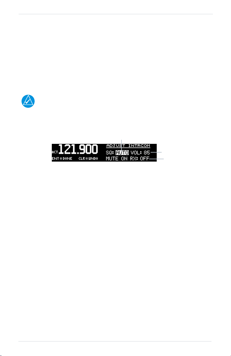
3.3.1 Adjust Intercom
The Adjust Intercom function sets the values for the intercom squelch, intercom
volume, and sets the intercom audio to mute when COM transmissions are received.
The Intercom On/Off function must be set to ON to make the Adjust Intercom
function available.
To enable ICS auto squelch, turn the knob one click counterclockwise past 0. When
squelch is set to auto, the squelch sensitivity adjusts automatically. When squelch is
set to 0, squelch is usually open. When squelch is set to 100, squelch is usually
closed. ICS auto squelch is available with software v2.10 or later.
Adjust Intercom Settings
1. Press ICS.
2. Turn the inner knob to set the ICS squelch (SQ) value.
3. Turn the outer knob to move to ICS volume (VOL) field.
4. Turn the inner knob to set the ICS volume level.
5. Turn outer knob to MUTE ON RX (software v2.10 or later).
6. Turn inner knob to ON or OFF. To mute when a radio transmission is received,
select ON.
7. Press ENT to save changes.
Press CLR to cancel the changes.
190-01182-00 Rev. D Garmin GTR 225/225A/225B Pilot’s Guide 3-7
Page 26

Functions
Mute On RX
AUX Audio Status
AUX Audio Volume
Intercom On or Off
3.3.2 AUX Audio
The AUX Audio function turns AUX Audio on or off, sets the AUX volume level, and
sets the AUX audio to mute when a COM radio transmission is received.
Adjust AUX Audio
1. Press FUNC.
2. Turn the outer knob to ICS CONFIGURATION.
3. Turn the inner knob to AUX AUDIO.
4. Press ENT.
5. Turn the inner knob to turn the AUX audio ON or OFF.
6. Turn the outer knob to VOL.
7. Turn the inner knob to set the AUX volume level.
8. Turn the outer knob to MUTE ON RX (available with software v2.10 or later).
9. Turn the inner knob to ON or OFF. To mute the AUX audio when a radio
transmission is received, select ON.
10. Press ENT to save new values.
Press CLR to cancel the changes.
3.3.3 Intercom On/Off
The Intercom On/Off function toggles the intercom on and off. If installed with a
remote switch, the intercom can also be remotely toggled on or off. The Intercom
On/Off function must be set to ON to make the Adjust Intercom function available.
Intercom On/Off
1. Press FUNC.
2. Turn the outer knob to ICS CONFIGURATION.
3. Turn the inner knob to INTRCOM ON/OFF.
4. Press ENT.
5. Turn the inner knob to set the Intercom ON or OFF.
6. Press ENT to save the selected value.
Press CLR to cancel the change.
3-8 Garmin GTR 225/225A/225B Pilot’s Guide 190-01182-00 Rev. D
Page 27

3.3.4 Speaker On/Off
Speaker On or Off
The Speaker On/Off function toggles the speaker output on and off.
Speaker On/Off
1. Press FUNC.
2. Turn the outer knob to ICS CONFIGURATION.
3. Turn the inner knob to SPEAKER ON/OFF.
4. Press ENT.
5. Turn the inner knob to set the speaker output ON or OFF.
6. Press ENT to save the selected value.
Press CLR to cancel the change.
Functions
190-01182-00 Rev. D Garmin GTR 225/225A/225B Pilot’s Guide 3-9
Page 28

Functions
NOTE
Channel Spacing
3.4 System Configuration
The System Configuration function displays the software version, database
information, and serial number. This information is helpful when contacting
customer support. It also allows setting the COM spacing, display brightness and
contrast, and to update databases.
3.4.1 COM Spacing
COM spacing may be selected between 8.33 kHz and 25 kHz to allow for regional
requirements.
When switching from 8.33 kHz to 25 kHz mode, any 8.33 kHz-specific user
frequencies will be deleted from the user frequency list. This only affects the user
frequencies within the 8.33 kHz spectrum.
COM Spacing
1. Press FUNC.
2. Turn the outer knob to SYS CONFIGURATION.
3. Turn the inner knob to COM SPACING.
4. Press ENT.
5. Turn the inner knob to set the COM spacing.
6. Press ENT to save the selected value.
Press CLR to cancel the change.
3-10 Garmin GTR 225/225A/225B Pilot’s Guide 190-01182-00 Rev. D
Page 29

Functions
NOTE
Offset Mode
Offset Value
3.4.2 COM Sidetone (Software v2.10 or later)
COM sidetone is the audio spoken into the COM microphone. This setting affects
the volume of the sidetone in the headsets for the COM during PTT. The COM
Sidetone Offset adjusts the amount that the COM sidetone volume level is offset
from the COM receiver volume level. The range can be adjusted from -10 (lowest) to
10 (highest), with 0 as the default.
COM Sidetone Pilot Control must be enabled by the installer.
COM Sidetone Page
1. Press FUNC.
2. Turn the outer knob to SYS CONFIGURATION.
3. Turn the inner knob to COM SIDETONE.
4. Press ENT.
5. Turn the inner knob to set mode of COM sidetone.
OFFSET: COM sidetone volume changes with adjustments of the COM volume
knob.
FIXED: COM sidetone volume is at level set at installation.
6. If offset mode is selected, turn the outer knob to OFFSET.
7. Turn the inner knob to set the offset value.
8. Press ENT to save selected values.
Press CLR to cancel the changes.
190-01182-00 Rev. D Garmin GTR 225/225A/225B Pilot’s Guide 3-11
Page 30

Functions
Current Display Brightness
Offset Value
Offset Value
3.4.3 Display Brightness
From the factory, the GTR 225 automatically adjusts its display brightness for the
current lighting conditions. A small sensor on the display is used for this function. A
manual adjustment is available for controlling the brightness level of the display as an
offset from the normal or zero position.
The limits of the adjustment range are: -10 (Low Display Intensity) and 100 (High
Display Intensity). A value above zero means brighter than normal and a value below
zero means darker than normal. The range can be adjusted by using the inner knob.
The GTR 225 will either control dimming based on the photocell or the lighting bus.
This is set in configuration mode during installation and is not selectable by the pilot.
Display Brightness Page
1. Press FUNC.
2. Turn the outer knob to SYS CONFIGURATION.
3. Turn the inner knob to DSPL BRT.
4. Press ENT.
5. Turn the inner knob to set the value.
6. Press ENT to save selected value.
Press CLR to cancel change.
3.4.4 Display Contrast
The display contrast has a range from -50 (low) and 50 (high) with 0 as the default.
The range can be adjusted by using the inner knob.
Display Contrast Page
1. Press FUNC.
2. Turn the outer knob to SYS CONFIGURATION.
3. Turn the inner knob to DSPL CONTRAST.
4. Press ENT.
5. Turn the inner knob to set the offset value.
6. Press ENT to save selected value.
Press CLR to cancel the change.
3-12 Garmin GTR 225/225A/225B Pilot’s Guide 190-01182-00 Rev. D
Page 31

Functions
NOTE
Database Cycle
Database Effectivity Date
USB Port
USB Cable
USB Flash Drive
3.4.5 Database Info
Database Info Page
1. Press FUNC.
2. Turn the outer knob to SYS CONFIGURATION.
3. Turn the inner knob to DATABASE INFO.
4. Press ENT.
5. Press the FUNC to exit page.
3.4.6 Load Database
The GTR 225 has a USB port to allow for easily updating the system databases.
Garmin recommends the use of a USB 2.0 compatible USB flash drive, formatted as
FAT32, for updating the database.
1. Insert the supplied cable into the USB port of the GTR 225.
2. Insert the USB flash drive into the other end of the cable.
3. Press FUNC.
4. Turn the outer knob to SYS CONFIGURATION.
5. Turn the inner knob to LOAD DATABASE.
6. Press ENT.
Database Update Page
190-01182-00 Rev. D Garmin GTR 225/225A/225B Pilot’s Guide 3-13
Page 32

Functions
NOTE
Version On Unit Version On Flash
Display Software Version
COM Software Version
Unit Serial Number
ID Is Used With The
flyGarmin Services
8 B
7. Verify the database version on flash drive.
Database Version Page
8. Press ENT to begin update.
9. Wait until the updating process is complete, then verify the correct database
is loaded onto the unit.
3.4.7 Software Version
Software Version Page
1. Press FUNC.
2. Turn the outer knob to SYS CONFIGURATION.
3. Turn the inner knob to SOFTWARE VER.
4. Press ENT.
5. Press FUNC to return to the main menu.
3.4.8 Serial Number
The ID consists of a combination of numbers 0-9 and letters A-F. The number 8 and
the letter B are distinguishable as depicted in the Serial Number screenshot.
Serial Number Page
1. Press FUNC.
2. Turn the outer knob to SYS CONFIGURATION.
3. Turn the inner knob to SERIAL NUMBER.
4. Press ENT.
5. Press FUNC to return to the main menu.
3-14 Garmin GTR 225/225A/225B Pilot’s Guide 190-01182-00 Rev. D
Page 33

Functions
Default Start Time
Hours
Minutes
Seconds
The Default (Starting) Value
3.5 Timers
The GTR 225 has both count up and count down timers, which may operate
simultaneously, and are shown in the lower right of the COM displays. The
countdown timer always takes precedence if it is running.
3.5.1 Setting Up the Count Down Timer
Count Down Timer Page
1. Press FUNC.
2. Turn the outer knob to TMR CONFIGURATION.
3. Turn the inner knob to COUNT DOWN.
4. Press ENT.
5. Press the inner knob to enter a starting timer value.
6. Turn the outer knob to move to set seconds, minutes, or hours.
7. Press ENT to confirm entry.
8. Press ENT to start or stop the timer.
9. Press the CLR key to reset the timer to the starting value.
10. Press the inner knob to change the starting timer value.
3.5.2 Setting Up the Count Up Timer
Count Up Timer Page
1. Press FUNC.
2. Turn the outer knob to TMR CONFIGURATION.
3. Turn the inner knob to COUNT UP.
4. Press ENT.
5. Press the ENT key to start the timer.
6. Press the ENT key again to stop the timer.
7. Press the CLR key to reset the timer to 0:00 and stop counting.
190-01182-00 Rev. D Garmin GTR 225/225A/225B Pilot’s Guide 3-15
Page 34

Functions
Timer Value
Count Down Timer Value
Highlighted When Counting Up
3.5.3 Viewing Timers in the COM Display
When a timer is active, the timer value will be shown in the lower right corner of the
COM display. While both timers may be actively counting at the same time, the
count down timer will have precedence in being shown. If the count down timer is
paused, the count up timer will then be shown until the count down timer is
restarted.
Timer Value Shown in the COM Display
Clearing and Stopping Displayed Timers
Clearing and Stopping Timers
1. To reset the timer, press CLR and then ENT.
2. To stop the displayed timer, press ENT twice.
When the count down timer reaches 0:00, it will continue counting as a count up
timer. The count down timer, which is counting up, will be highlighted. A count up
timer will continue counting separately.
COM Display with Count Down Timer Now Counting Up
3-16 Garmin GTR 225/225A/225B Pilot’s Guide 190-01182-00 Rev. D
Page 35

Database Information
NOTE
NOTE
4 Database Information
The data contained in the frequency database comes from government agencies.
Garmin accurately processes and cross-validates the data, but cannot guarantee the
accuracy and completeness of the data.
The GTR 225 uses a standard USB flash drive to load the frequency database into the
GTR 225. The flash drive is not provided by Garmin. The frequency database is stored
internally and the USB flash drive is only used to transfer the database into the unit.
The following equipment is required to perform the update:
• Windows-compatible PC computer (Windows 2000, XP, Vista, or Windows
7 recommended)
• USB 2.0 compatible USB flash drive formatted as FAT32
• External USB cable
• Updated database obtained from the Garmin website
4.1 Downloading the Frequency Database
The GTR 225’s system ID is required when downloading the frequency database. See
section 3.4.8 for details on the system ID.
The Garmin databases can be updated by following the instructions on
https://fly.garmin.com/fly-garmin. The frequency database is updated on a 28-day
cycle.
4.2 Updating the GTR 225 Frequency Database
See section 3.4.6 for details on loading the database into the GTR 225.
190-01182-00 Rev. D Garmin GTR 225/225A/225B Pilot’s Guide 4-1
Page 36

INTENTIONALLY LEFT BLANK
4-2 Garmin GTR 225/225A/225B Pilot’s Guide 190-01182-00 Rev. D
Page 37

Troubleshooting
5 Troubleshooting
If efforts to resolve the problem are not successful, contact your dealer or the factory
for technical assistance. Please have the following information ready:
• System configuration (products, antennas, mounting locations, etc.)
• Model number, part number, and serial number
• Software versions
• Description of the problem
• Efforts made to isolate/solve the problem
For aviation product support, visit flyGarmin.com.
190-01182-00 Rev. D Garmin GTR 225/225A/225B Pilot’s Guide 5-1
Page 38

Troubleshooting
PROBLEM POSSIBLE CAUSE ACTION
GTR 225 does not power
on
GTR 225 does not
transmit
Intercom doesn’t function
Unable to change active
frequency
Display shows
“COM Radio Needs
Service” at start-up
No power to the GTR
225.
Faulty electrical wiring or
connection.
No power to COM.
Mic key connection
It can be enabled or
disabled via a remote
mounted switch or via the
menu.
No voice activation, or if
must talk too loud.
COM Radio not
communicating. The
radio may also be in
lockout mode. In this case
the radio would be tuned
to 121.50 and the active
freq would not be able to
be changed.
Corrupted system
calibration parameters
Check power
connections, breakers,
and main avionics switch.
Contact your dealer to
perform electrical system
test.
Check power
connections.
Check Mic key input
connection.
Check connections.
Check ICS page, Intercom
On/Off, Adjust Intercom.
If in Lock Out mode, press
the external COM
FLIP/FLOP key for two
seconds to return to
normal operation or cycle
the avionics power. If the
condition persists, contact
dealer.
Contact factory.
5-2 Garmin GTR 225/225A/225B Pilot’s Guide 190-01182-00 Rev. D
Page 39

Troubleshooting
Message
5.1 Messages
When a message has been issued by the unit, the message will be shown on the
display. After viewing the messages, press the ENT key to acknowledge the message
and return to the previously viewed page. An acknowledged message will not be
redisplayed even if the condition persists. Messages provide an aid to
troubleshooting system operation.
Display of Message
Messages
MESSAGE DESCRIPTION ACTION
The COM radio is
COM RADIO -
COM radio needs service.
COM RADIO -
COM radio may be
inoperative.
COM RADIO -
COM overtemp or
undervoltage. Reducing
transmitter power.
COM RADIO -
COM locked to 121.5
MHz. Hold remote COM
transfer key to exit.
190-01182-00 Rev. D Garmin GTR 225/225A/225B Pilot’s Guide 5-3
reporting that it needs
service. The COM radio
may continue to function.
The COM radio is not
communicating properly
with the system.
COM radio is in overtemp
or undervoltage mode
and transmitting power
has been reduced to
prevent damage to the
COM radio. Radio range
will be reduced.
COM radio is locked to
121.5 MHz.
Cycle the power to the
COM radio. Contact
dealer for service.
Press and hold the volume
knob or the external
COM remote transfer
(COM RMT XFR) switch, if
installed – this will force
the COM radio to 121.5
MHz. Contact dealer for
service.
Decrease length of COM
transmissions, decrease
cabin temperature and
increase cabin airflow
(especially near the GTR).
Check aircraft voltage
and reduce electrical load
as necessary. Contact
dealer for service if this
message persists.
The external COM remote
transfer (COM RMT XFR)
switch has been held and
the COM radio is tuned
to 121.5. To exit this
mode, hold the COM
remote transfer (COM
RMT XFR) switch for two
seconds.
Page 40

Troubleshooting
NOTE
MESSAGE DESCRIPTION ACTION
COOLING FAN -
The cooling fan has failed.
DISPLAY -
Display board needs
service.
FEATURE UNLOCK
FAILURE -
NO UNLOCK FILE -
The GTR cooling fan is
powered, but it is not
turning at the desired
RPM.
The display board is
indicating that it needs
service.
The database on the USB
flash drive is corrupt or
the system ID in the
database does not match
the unit’s system ID.
The USB flash drive is
missing the feature
unlock file for the
frequency database.
Decrease cabin
temperature and increase
cabin airflow (especially
near the GTR) to prevent
damage to the unit.
Contact dealer for
service.
Contact dealer for service.
Verify that the correct
system ID is entered into
flyGarmin.com when
downloading the
database. Contact
Garmin Customer
Support if this message
persists.
Verify the correct system
ID is entered on
flyGarmin.com and the
frequency database is
downloaded onto the
USB flash drive. Contact
Garmin Customer
Support if this message
persists.
The GTR 225’s system ID is required when downloading the frequency database. See
section 3.4.8 for details on the system ID.
5-4 Garmin GTR 225/225A/225B Pilot’s Guide 190-01182-00 Rev. D
Page 41

MESSAGE DESCRIPTION ACTION
POWER ALERT -
Unit will shut down if
power switch is not
restored immediately.
REMOTE KEY STUCK -
COM push-to-talk key is
stuck.
REMOTE KEY STUCK -
COM remote transfer key
is stuck.
REMOTE KEY STUCK -
COM remote frequency
increment key is stuck.
REMOTE KEY STUCK -
COM remote frequency
decrement key is stuck.
Power has been removed
from the unit.
The Push To Talk
key/switch has been in
pressed position for at
least 30 seconds. This
input will now be ignored
and the COM radio will
no longer transmit.
The remote COM transfer
(COM RMT XFR)
key/switch has been in
pressed position for at
least 30 seconds. This
input will now be
ignored. This input is not
available in all
installations.
The remote COM
frequency increment
(COM CHAN UP)
key/switch has been in
pressed position for at
least 30 seconds. This
input will now be
ignored. This input is not
available in all
installations.
The remote COM
frequency decrement
(COM CHAN DN)
key/switch has been in
pressed position for at
least 30 seconds. This
input will now be
ignored. This input is not
available in all
installations.
Re-apply power to the
unit.
Verify the Push To Talk
key/switch is not stuck.
Contact dealer for service
if this message persists.
Verify the COM RMT XFR
key/switch is not stuck.
Contact dealer for service
if this message persists.
Verify the COM CHAN UP
key/switch is not stuck.
Contact dealer for service
if this message persists.
Verify the COM CHAN DN
key/switch is not stuck.
Contact dealer for service
if this message persists.
Troubleshooting
190-01182-00 Rev. D Garmin GTR 225/225A/225B Pilot’s Guide 5-5
Page 42

INTENTIONALLY LEFT BLANK
5-6 Garmin GTR 225/225A/225B Pilot’s Guide 190-01182-00 Rev. D
Page 43

Page 44

190-01182-00 Rev. D
 Loading...