

Page 1
Adafruit 1.44" Color TFT with Micro SD Socket
Created by lady ada
Last updated on 2020-10-19 10:58:59 AM EDT
Page 2
Overview
This lovely little display breakout is the best way to add a small, colorful and bright display to any project. Since the
display uses 4-wire SPI to communicate and has its own pixel-addressable frame buffer, it can be used with every kind
of microcontroller. Even a very small one with low memory and few pins available!
The 1.44" display has 128x128 color pixels. Unlike the low cost "Nokia 6110" and similar LCD displays, which are CSTN
type and thus have poor color and slow refresh, this display is a true TFT! The TFT driver (ST7735R) can display full 16-
bit color using our library code.
© Adafruit Industries https://learn.adafruit.com/adafruit-1-44-color-tft-with-micro-sd-socket Page 3 of 52
Page 3
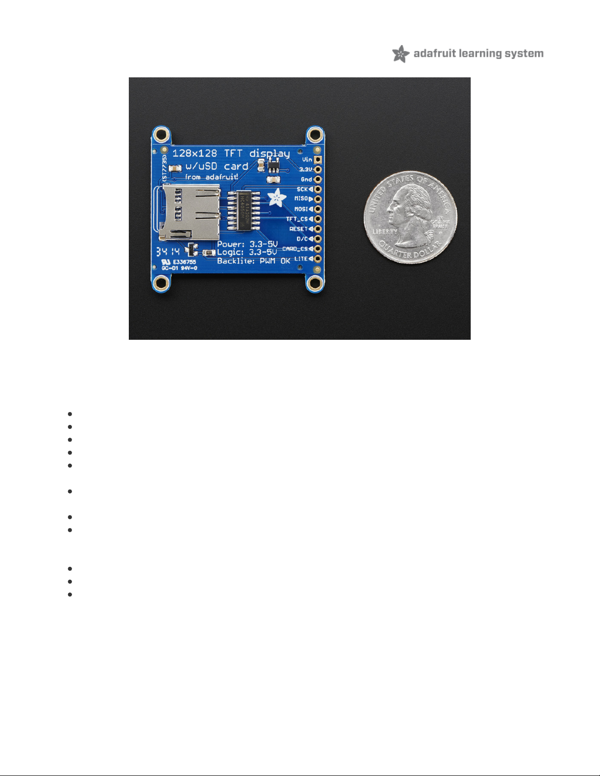
The breakout has the TFT display soldered on (it uses a delicate flex-circuit connector) as well as a ultra-low-dropout
3.3V regulator and a 3/5V level shifter so you can use it with 3.3V or 5V power and logic. We also had a little space so
we placed a microSD card holder so you can easily load full color bitmaps from a FAT16/FAT32 formatted microSD
card. The microSD card is not included, but you can pick one up here (http://adafru.it/102).
Of course, we wouldn't just leave you with a datasheet and a "good luck!" - we've written a full open source graphics
library that can draw pixels, lines, rectangles, circles, text and bitmaps as well as example code and a wiring
© Adafruit Industries https://learn.adafruit.com/adafruit-1-44-color-tft-with-micro-sd-socket Page 4 of 52
Page 4

tutorial (https://adafru.it/ckK). The code is written for Arduino but can be easily ported to your favorite microcontroller!
© Adafruit Industries https://learn.adafruit.com/adafruit-1-44-color-tft-with-micro-sd-socket Page 5 of 52
Page 5
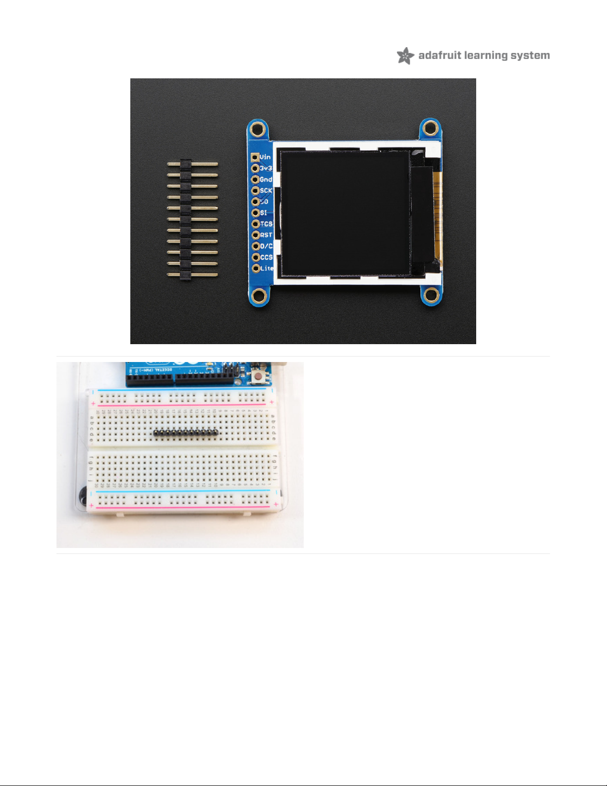
Pinouts
This color display uses SPI to receive image data. That means you need at least 4 pins - clock, data in, tft cs and d/c. If
you'd like to have SD card usage too, add another 2 pins - data out and card cs. However, there's a couple other pins
you may want to use, lets go thru them all!
3-5V / Vin - this is the power pin, connect to 3-5VDC - it has reverse polarity protection but try to wire it right!
3.3Vout - this is the 3.3V output from the onboard regulator
GND - this is the power and signal ground pin
CLK - this is the SPI clock input pin
MISO - this is the SPI Microcontroller In Serial Out pin, its used for the SD card. It isn't used for the TFT display
which is write-only
MOSI - this is the SPI Microcontroller Out Serial In pin, it is used to send data from the microcontroller to the SD
card and/or TFT
TFT_CS - this is the TFT SPI chip select pin
RST - this is the TFT reset pin. Connect to ground to reset the TFT! Its best to have this pin controlled by the
library so the display is reset cleanly, but you can also connect it to the Arduino Reset pin, which works for most
cases.
D/C - this is the TFT SPI data or command selector pin
Card CS / CCS - this is the SD card chip select, used if you want to read from the SD card.
Lite - this is the PWM input for the backlight control. It is by default pulled high (backlight on) you can PWM at any
frequency or pull down to turn the backlight off
© Adafruit Industries https://learn.adafruit.com/adafruit-1-44-color-tft-with-micro-sd-socket Page 6 of 52
Page 6
Assembly
Prepare the header strip:
Cut the strip to length if necessary. It will be easier to
solder if you insert it into a breadboard - long pins down
© Adafruit Industries https://learn.adafruit.com/adafruit-1-44-color-tft-with-micro-sd-socket Page 7 of 52
Page 7
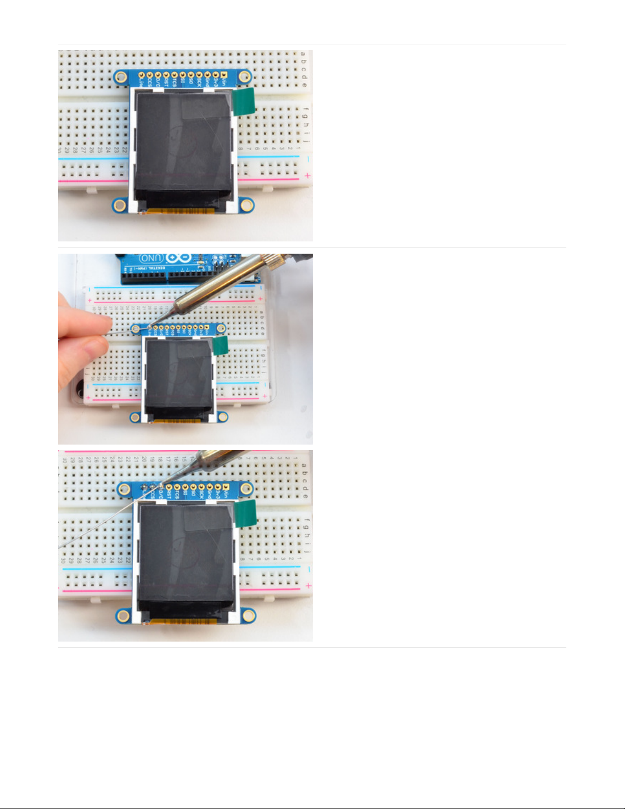
Add the breakout board:
Place the breakout board over the pins so that the short
pins poke through the breakout pads
And Solder!
Be sure to solder all pins for reliable electrical contact.
(For tips on soldering, be sure to check out our Guide to
Excellent Soldering
(https://adafru.it/aTk)
).
© Adafruit Industries https://learn.adafruit.com/adafruit-1-44-color-tft-with-micro-sd-socket Page 8 of 52
Page 8
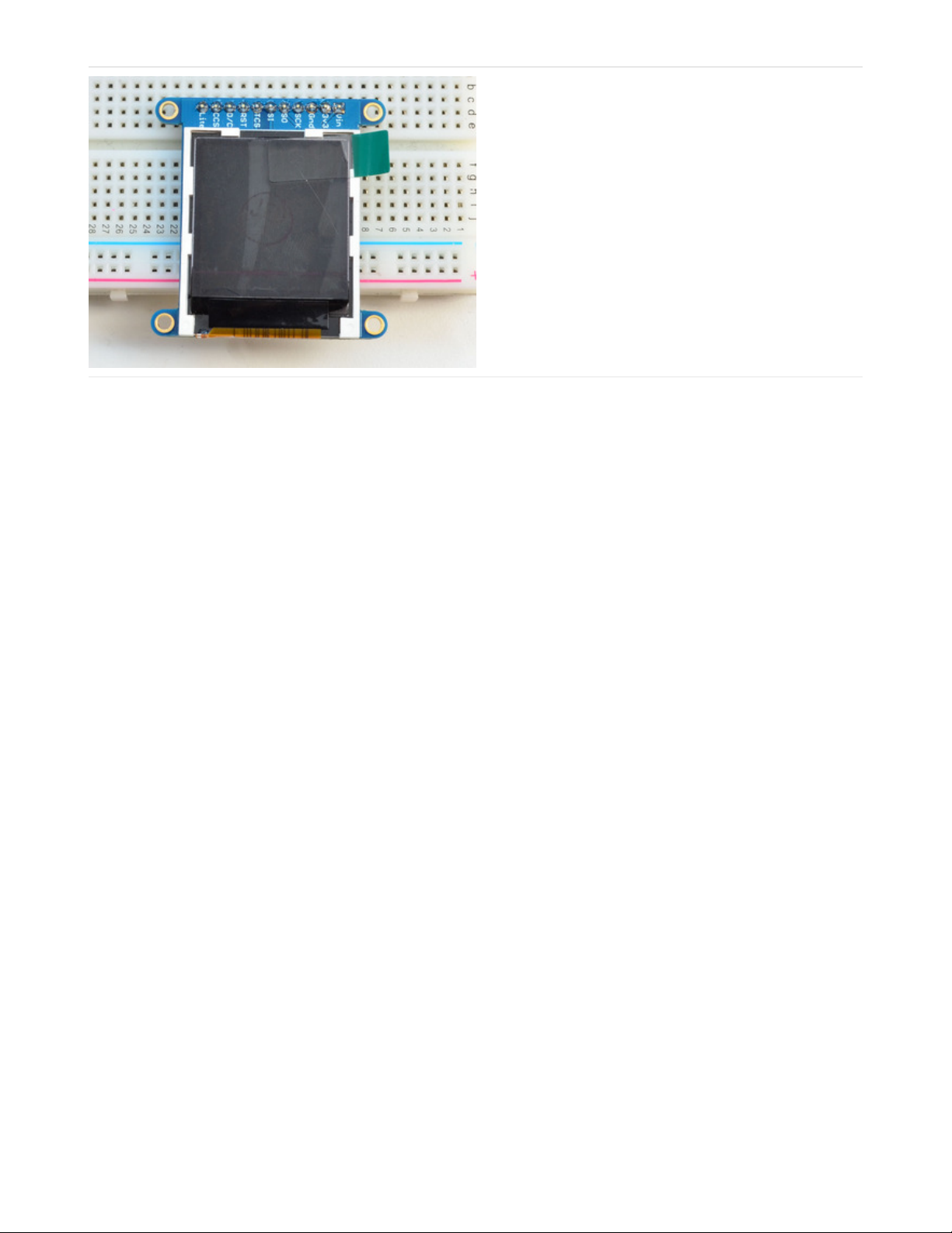
You're done! Check your solder joints visually and
continue onto the next steps
© Adafruit Industries https://learn.adafruit.com/adafruit-1-44-color-tft-with-micro-sd-socket Page 9 of 52
Page 9
Wiring & Test
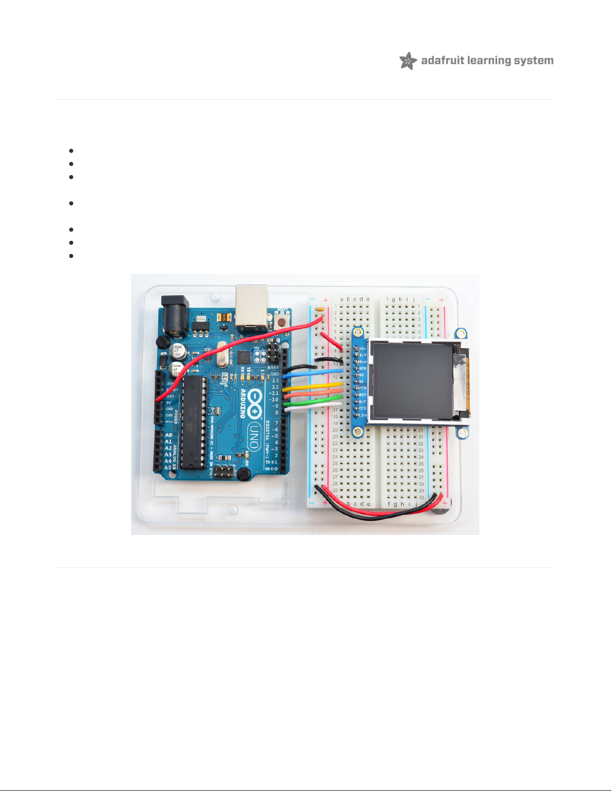
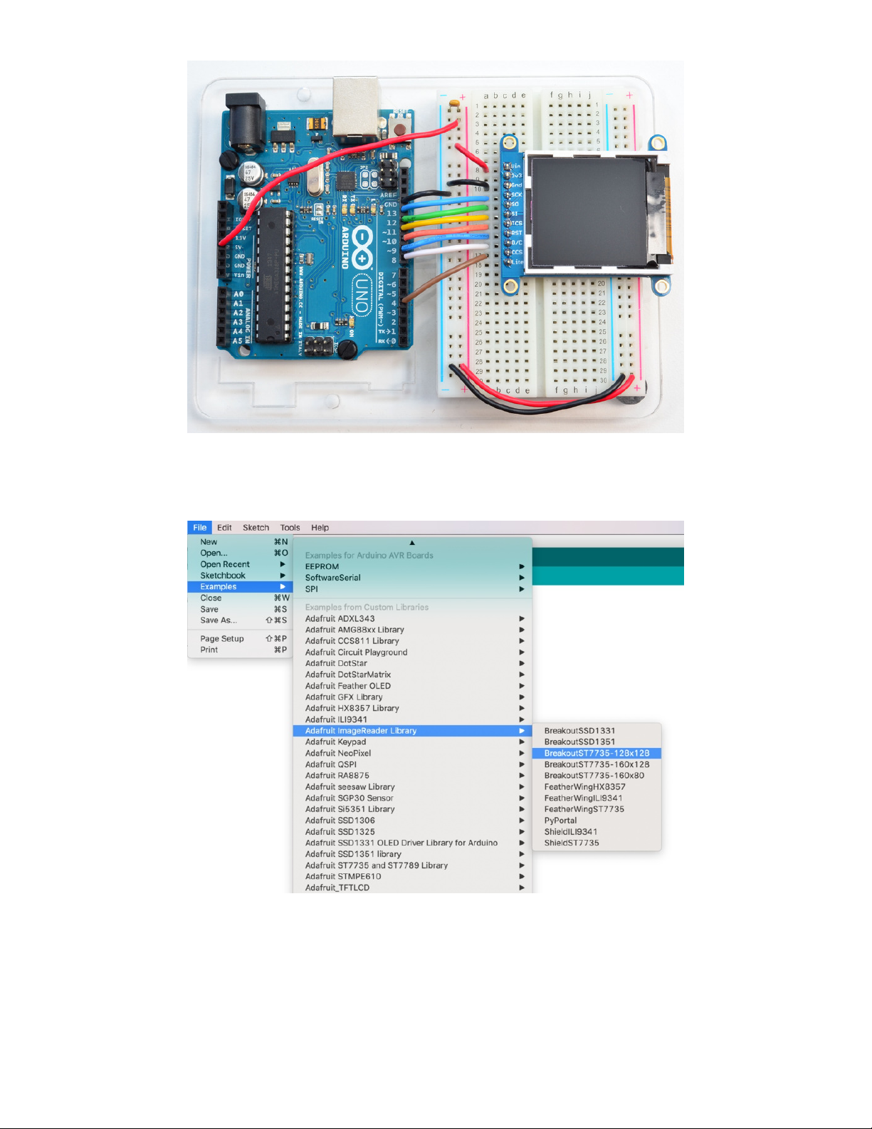
Wiring
Wiring up the display in SPI mode is pretty easy as there's not that many pins! We'll be using hardware SPI, but you can
also use software SPI (any pins) later. Start by connecting the power pins
3-5V Vin connects to the Arduino 5V pin
GND connects to Arduino ground
CLK connects to SPI clock. On Arduino Uno/Duemilanove/328-based, thats Digital 13. On Mega's, its Digital 52
and on Leonardo/Due its ICSP-3 (See SPI Connections for more details (https://adafru.it/d5h))
MOSI connects to SPI MOSI. On Arduino Uno/Duemilanove/328-based, thats Digital 11. On Mega's, its Digital 51
and on Leonardo/Due its ICSP-4 (See SPI Connections for more details (https://adafru.it/d5h))
CS connects to our SPI Chip Select pin. We'll be using Digital 10 but you can later change this to any pin
RST connects to our TFT reset pin. We'll be using Digital 9 but you can later change this pin too.
D/C connects to our SPI data/command select pin. We'll be using Digital 8 but you can later change this pin too.
Install Arduino Libraries
We have example code ready to go for use with these TFTs. It's written for Arduino, which should be portable to any
microcontroller by adapting the C++ source.
Three
libraries need to be installed using the Arduino Library Manager…this is the preferred and modern way. From the
Arduino “Sketch” menu, select “Include Library” then “Manage Libraries…”
© Adafruit Industries https://learn.adafruit.com/adafruit-1-44-color-tft-with-micro-sd-socket Page 10 of 52
Page 10
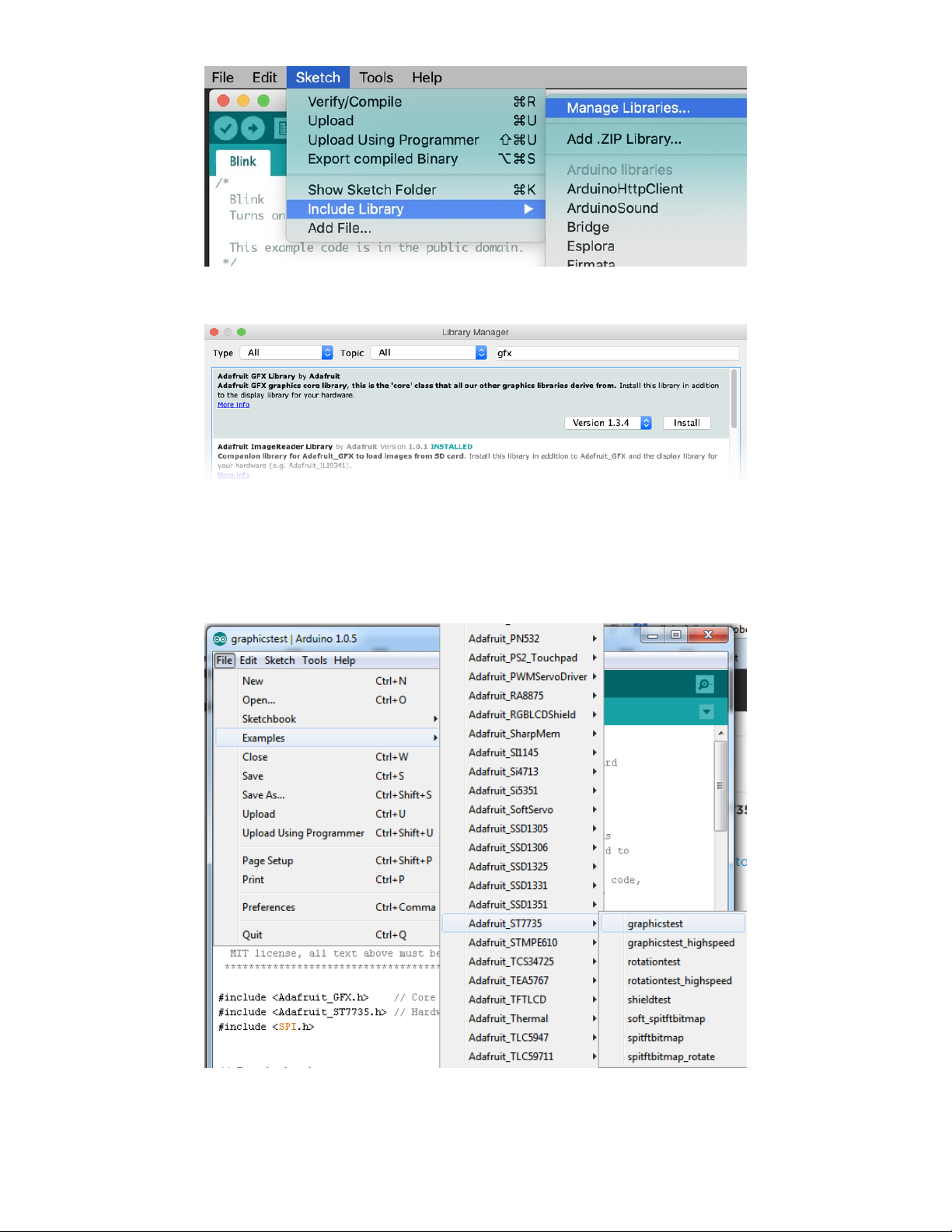
Type “gfx” in the search field to quickly find the first library — Adafruit_GFX:
Repeat the search and install steps, looking for the Adafruit_ST7735 library. If using an older Arduino IDE (pre-1.8.10),
also locate and install Adafruit_BusIO.
After restarting the Arduino software, you should see a new example folder called Adafruit_ST7735 and inside, an
example called graphicstest.
In the graphicstest source code, you need to changes some code for this to work. Start by looking for the lines as
© Adafruit Industries https://learn.adafruit.com/adafruit-1-44-color-tft-with-micro-sd-socket Page 11 of 52
Page 11
follows:
// Use this initializer if you're using a 1.8" TFT
tft.initR(INITR_BLACKTAB); // initialize a ST7735S chip, black tab
// Use this initializer (uncomment) if you're using a 1.44" TFT
//tft.initR(INITR_144GREENTAB); // initialize a ST7735S chip, black tab
Comment out the line that initializes the Black Tab, and uncomment the second so it initializes with Green Tab, so it
looks like:
// Use this initializer if you're using a 1.8" TFT
//tft.initR(INITR_BLACKTAB); // initialize a ST7735S chip, black tab
// Use this initializer (uncomment) if you're using a 1.44" TFT
tft.initR(INITR_144GREENTAB); // initialize a ST7735S chip, black tab
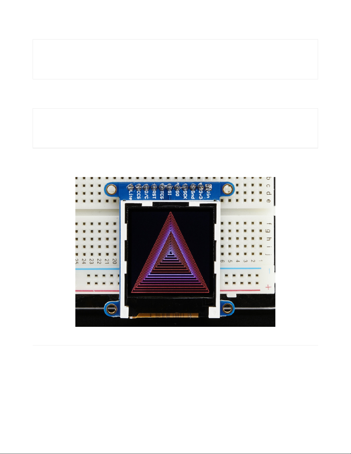
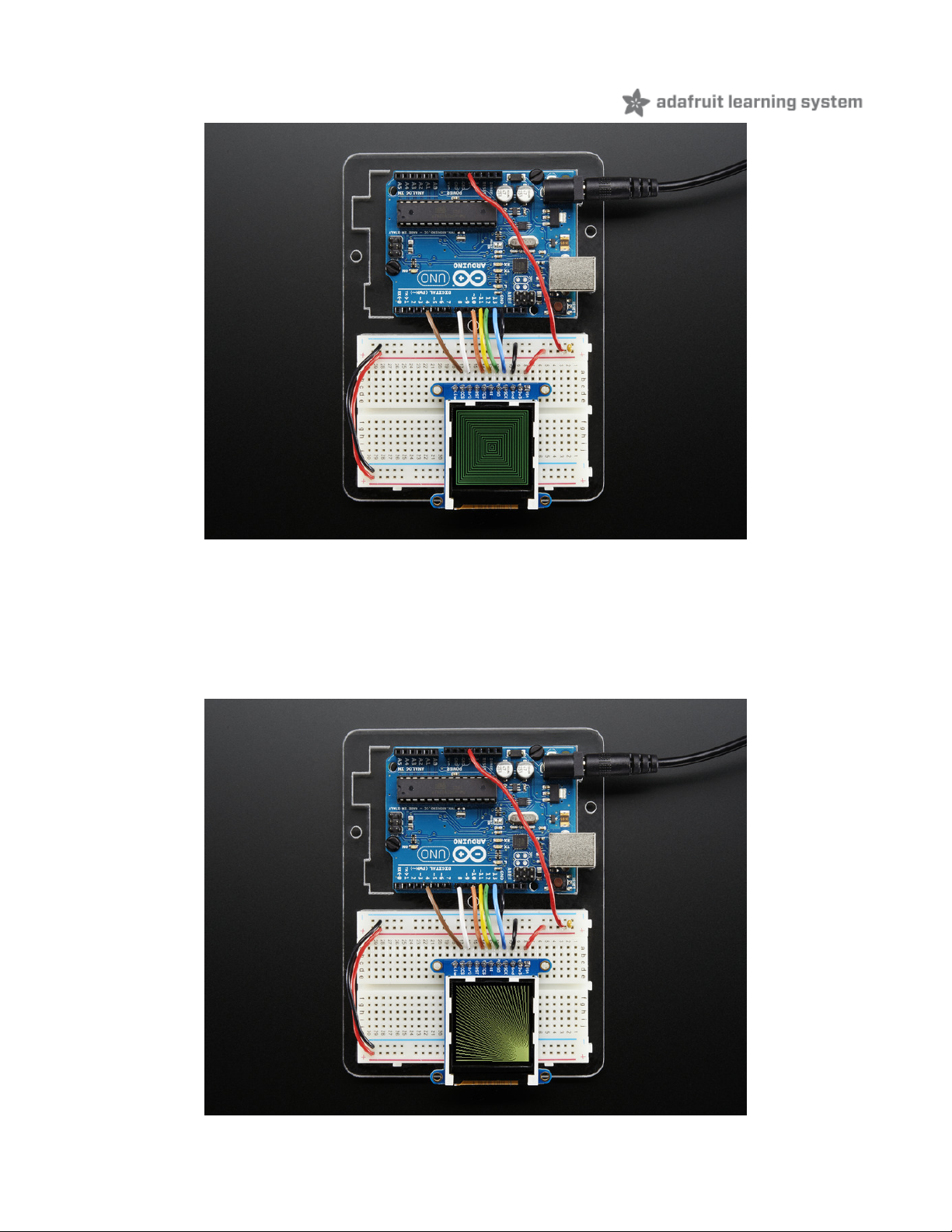
Now upload the sketch to your Arduino. You may need to press the Reset button to reset the arduino and TFT. You
should see a collection of graphical tests draw out on the TFT.
Changing Pins
Now that you have it working, there's a few things you can do to change around the pins.
If you're using Hardware SPI, the CLOCK and MOSI pins are 'fixed' and cant be changed. But you can change to
software SPI, which is a bit slower, and that lets you pick any pins you like. Find these lines:
© Adafruit Industries https://learn.adafruit.com/adafruit-1-44-color-tft-with-micro-sd-socket Page 12 of 52
Page 12

// Option 1 (recommended): must use the hardware SPI pins
// (for UNO thats sclk = 13 and sid = 11) and pin 10 must be
// an output. This is much faster - also required if you want
// to use the microSD card (see the image drawing example)
Adafruit_ST7735 tft = Adafruit_ST7735(TFT_CS, TFT_DC, TFT_RST);
// Option 2: use any pins but a little slower!
#define TFT_SCLK 13 // set these to be whatever pins you like!
#define TFT_MOSI 11 // set these to be whatever pins you like!
//Adafruit_ST7735 tft = Adafruit_ST7735(TFT_CS, TFT_DC, TFT_MOSI, TFT_SCLK, TFT_RST);
Comment out option 1, and uncomment option 2. Then you can change the TFT_ pins to whatever pins you'd like!
You can also save a pin by setting
#define TFT_RST 9
to
#define TFT_RST 0
and connecting the RST line to the Arduino Reset pin. That way the Arduino will auto-reset the TFT as well.
© Adafruit Industries https://learn.adafruit.com/adafruit-1-44-color-tft-with-micro-sd-socket Page 13 of 52
Page 13
Adafruit GFX library
The Adafruit_GFX library for Arduino provides a common syntax and set of graphics functions for all of our TFT, LCD
and OLED displays. This allows Arduino sketches to easily be adapted between display types with minimal fuss…and
any new features, performance improvements and bug fixes will immediately apply across our complete offering of
color displays.
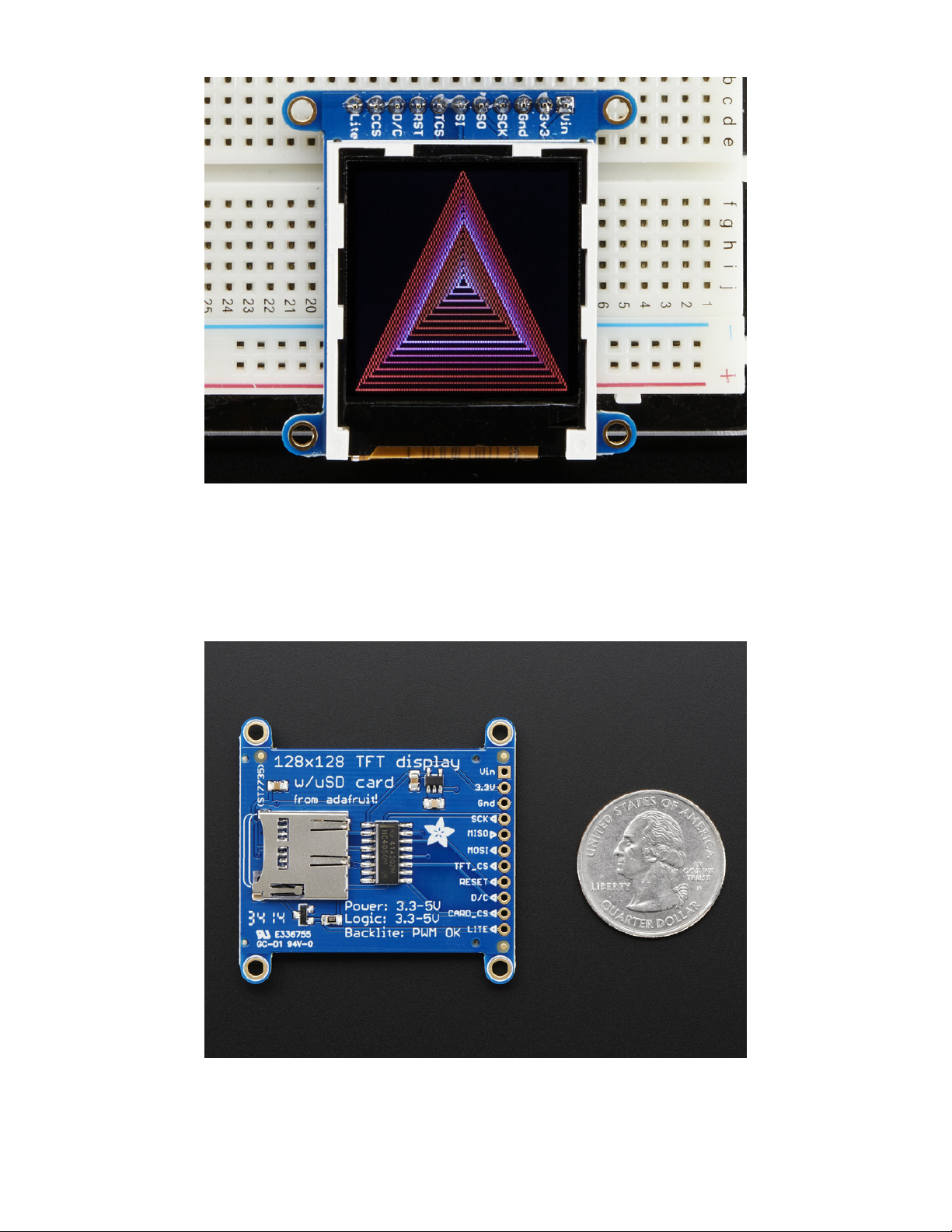
The GFX library is what lets you draw points, lines, rectangles, round-rects, triangles, text, etc.
© Adafruit Industries https://learn.adafruit.com/adafruit-1-44-color-tft-with-micro-sd-socket Page 14 of 52
Page 14

Check out our detailed tutorial here http://learn.adafruit.com/adafruit-gfx-graphics-library (https://adafru.it/aPx) It covers
the latest and greatest of the GFX library!
© Adafruit Industries https://learn.adafruit.com/adafruit-1-44-color-tft-with-micro-sd-socket Page 15 of 52
Page 15
Drawing Bitmaps
There is a built in microSD card slot into the breakout, and we can use that to load bitmap images! You will need a
microSD card formatted FAT16 or FAT32 (they almost always are by default).
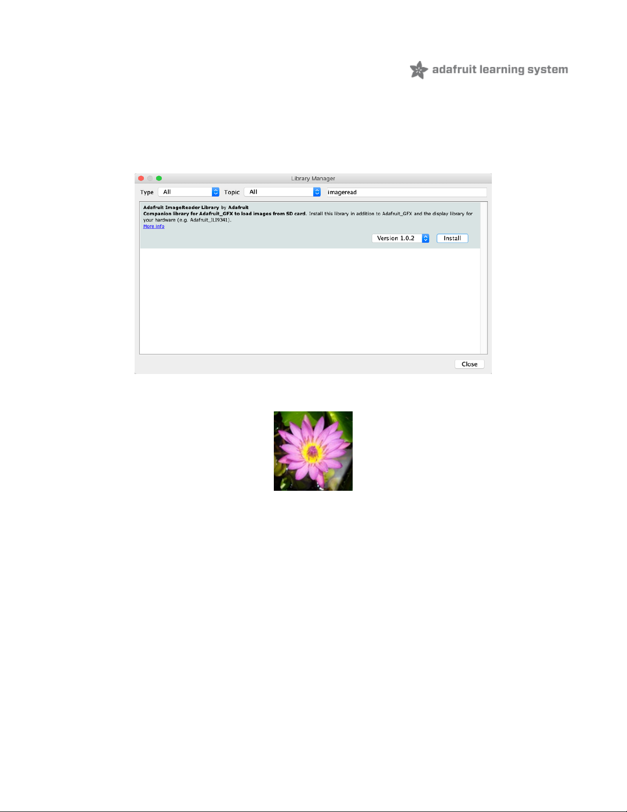
It's really easy to draw bitmaps. We have a library for it, Adafruit_ImageReader, which can be installed through the
Arduino Library Manager (Sketch→Include Library→Manage Libraries…). Enter “imageread” in the search field and the
library is easy to spot:
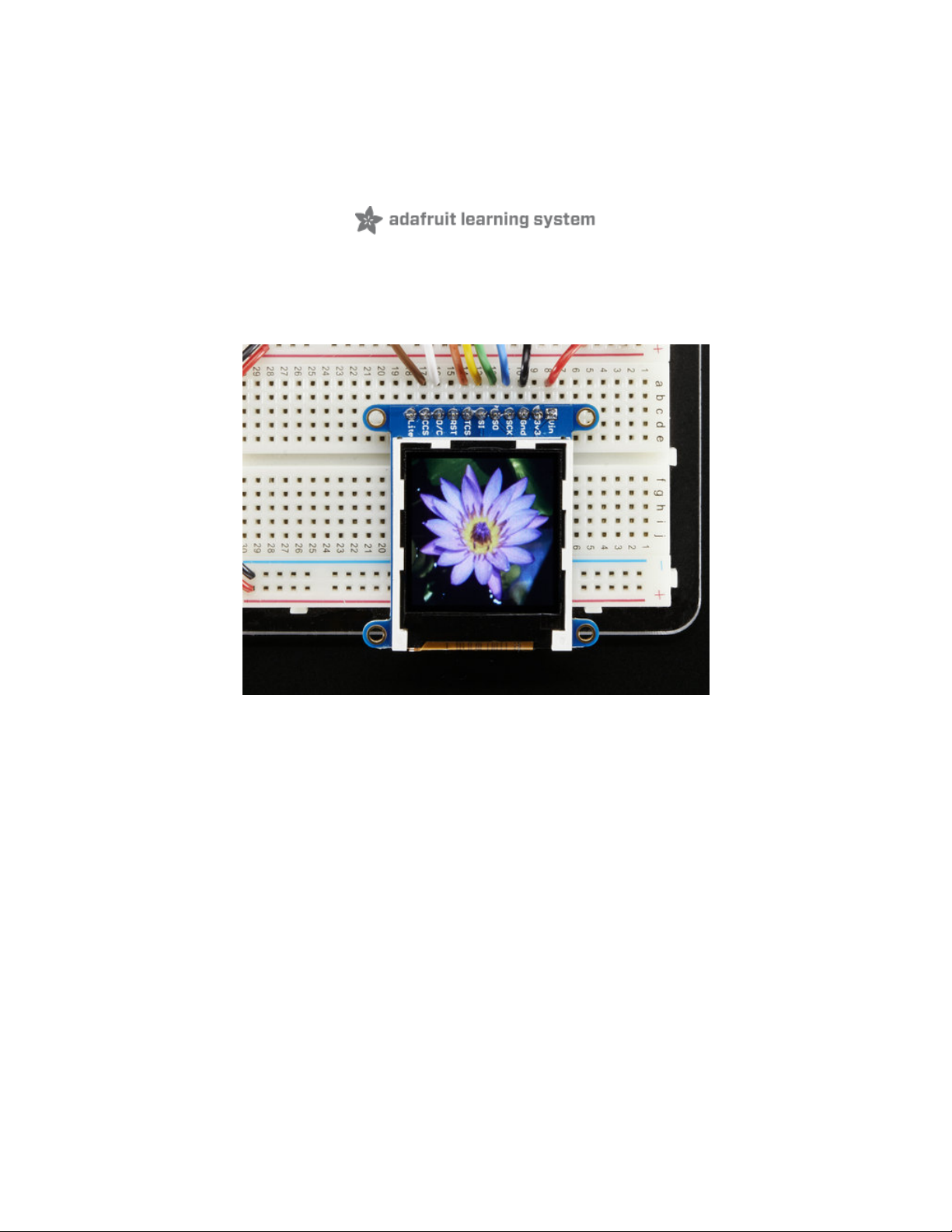
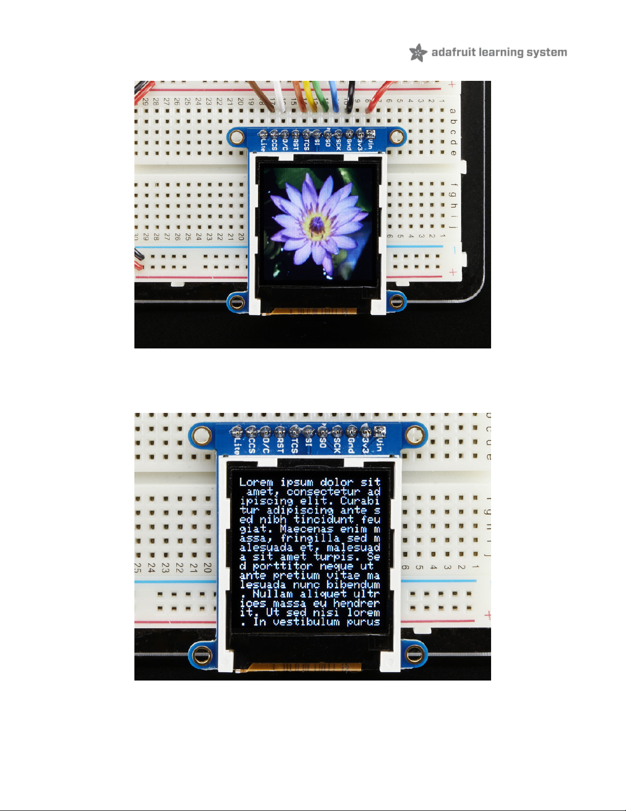
Let's start by downloading this image of a lily:
Copy lily128.bmp into the base directory of a microSD card and insert it into the microSD socket in the breakout.
Two more wires are required to interface with the onboard SD card.
You'll need to connect up the MISO pin to the SPI MISO line on your microcontroller. On Arduino
Uno/Duemilanove/328-based, thats Digital 12. On Mega's, its Digital 50 and on Leonardo/Due its ICSP-1 (See SPI
Connections for more details (https://adafru.it/d5h))
Also, CCS pin to Digital 4 on your Arduino as well. You can change this pin later, but stick with this for now.
© Adafruit Industries https://learn.adafruit.com/adafruit-1-44-color-tft-with-micro-sd-socket Page 16 of 52
Page 16
You may want to try the SD library examples before continuing, especially one that lists all the files on the SD card
Open the File→examples→Adafruit ImageReader Library→BreakoutST7735 - 128x128 example
In the example, find the following section of code:
© Adafruit Industries https://learn.adafruit.com/adafruit-1-44-color-tft-with-micro-sd-socket Page 17 of 52
Page 17

// Load full-screen BMP file 'rgbwheel.bmp' at position (0,0) (top left).
// Notice the 'reader' object performs this, with 'tft' as an argument.
Serial.print(F("Loading rgbwheel.bmp to screen..."));
stat = reader.drawBMP("/rgbwheel.bmp", tft, 0, 0);
reader.printStatus(stat); // How'd we do?
On the line with reader.drawBMP() change "/rgbwheel.bmp" to "/lily128.bmp" .
After that, upload it to your Arduino. When the Arduino restarts, you should see the flower as below!
To make new bitmaps, make sure they are less than 128 by 128 pixels and save them in 24-bit BMP format! They must
be in 24-bit format, even if they are not 24-bit color as that is the easiest format for the Arduino. You can rotate images
using the setRotation() procedure
You can draw as many images as you want - dont forget the names must be less than 8 characters long. Just copy the
BMP drawing routines below loop() and call
bmpDraw(bmpfilename, x, y);
For each bitmap. They can be smaller than 128x128 and placed in any location on the screen.
© Adafruit Industries https://learn.adafruit.com/adafruit-1-44-color-tft-with-micro-sd-socket Page 18 of 52
Page 18

CircuitPython Displayio
Quickstart
You will need a board capable of running CircuitPython such as the Metro M0 Express or the Metro M4 Express. You
can also use boards such as the Feather M0 Express or the Feather M4 Express. We recommend either the Metro M4
or the Feather M4 Express because it's much faster and works better for driving a display. For this guide, we will be
using a Feather M4 Express. The steps should be about the same for the Feather M0 Express or either of the Metros. If
you haven't already, be sure to check out our Feather M4 Express (https://adafru.it/EEm) guide.
Preparing the Breakout
Before using the TFT Breakout, you will need to solder the headers or some wires to it. Be sure to check out
the Adafruit Guide To Excellent Soldering (https://adafru.it/drI). After that the breakout should be ready to go.
Wiring the Breakout to the Feather
3-5V VIN connects to the Feather 3V pin
GND connects toFeather ground
SCK connects to SPI clock. On the Feather that's SCK.
SO connects to SPI MISO. On the Feather that's MI
SI connects to SPI MOSI. On the Feather that's MO
TCS connects to our SPI Chip Select pin. We'll be using Digital 9 but you can later change this to any pin
D/C connects to our SPI data/command select pin. We'll be using Digital 10 but you can later change this pin too.
RST connects to our reset pin. We'll be using Digital 6 but you can later change this pin too.
Adafruit Feather M4 Express - Featuring ATSAMD51
$22.95
IN STOCK
Add To Cart
© Adafruit Industries https://learn.adafruit.com/adafruit-1-44-color-tft-with-micro-sd-socket Page 19 of 52
Page 19

https://adafru.it/FyY
https://adafru.it/FyY
Required CircuitPython Libraries
To use this display with displayio , there is only one required library.
https://adafru.it/EGk
https://adafru.it/EGk
First, make sure you are running the latest version of Adafruit CircuitPython (https://adafru.it/Amd) for your board.
Next, you'll need to install the necessary libraries to use the hardware--carefully follow the steps to find and install
these libraries from Adafruit's CircuitPython library bundle (https://adafru.it/zdx). Our introduction guide has a great
page on how to install the library bundle (https://adafru.it/ABU) for both express and non-express boards.
Remember for non-express boards, you'll need to manually install the necessary libraries from the bundle:
adafruit_st7735r
Before continuing make sure your board's lib folder or root filesystem has the adafruit_st7735r file copied over.
Code Example Additional Libraries
For the Code Example, you will need an additional library. We decided to make use of a library so the code didn't get
overly complicated.
https://adafru.it/FiA
https://adafru.it/FiA
Go ahead and install this in the same manner as the driver library by copying the adafruit_display_text folder over to
the lib folder on your CircuitPython device.
CircuitPython Code Example
© Adafruit Industries https://learn.adafruit.com/adafruit-1-44-color-tft-with-micro-sd-socket Page 20 of 52
Page 20

"""
This test will initialize the display using displayio and draw a solid green
background, a smaller purple rectangle, and some yellow text.
"""
import board
import terminalio
import displayio
from adafruit_display_text import label
from adafruit_st7735r import ST7735R
# Release any resources currently in use for the displays
displayio.release_displays()
spi = board.SPI()
tft_cs = board.D5
tft_dc = board.D6
display_bus = displayio.FourWire(
spi, command=tft_dc, chip_select=tft_cs, reset=board.D9
)
display = ST7735R(display_bus, width=128, height=128, colstart=2, rowstart=1)
# Make the display context
splash = displayio.Group(max_size=10)
display.show(splash)
color_bitmap = displayio.Bitmap(128, 128, 1)
color_palette = displayio.Palette(1)
color_palette[0] = 0x00FF00 # Bright Green
bg_sprite = displayio.TileGrid(color_bitmap, pixel_shader=color_palette, x=0, y=0)
splash.append(bg_sprite)
# Draw a smaller inner rectangle
inner_bitmap = displayio.Bitmap(108, 108, 1)
inner_palette = displayio.Palette(1)
inner_palette[0] = 0xAA0088 # Purple
inner_sprite = displayio.TileGrid(inner_bitmap, pixel_shader=inner_palette, x=10, y=10)
splash.append(inner_sprite)
# Draw a label
text = "Hello World!"
text_area = label.Label(terminalio.FONT, text=text, color=0xFFFF00, x=30, y=64)
splash.append(text_area)
while True:
pass
Let's take a look at the sections of code one by one. We start by importing the board so that we can
initialize SPI , displayio , terminalio for the font, a label , and the adafruit_st7735r driver.
© Adafruit Industries https://learn.adafruit.com/adafruit-1-44-color-tft-with-micro-sd-socket Page 21 of 52
Page 21

import board
import displayio
import terminalio
from adafruit_display_text import label
from adafruit_st7735r import ST7735R
Next we release any previously used displays. This is important because if the Feather is reset, the display pins are not
automatically released and this makes them available for use again.
displayio.release_displays()
Next, we set the SPI object to the board's SPI with the easy shortcut function board.SPI() . By using this function, it
finds the SPI module and initializes using the default SPI parameters.
spi = board.SPI()
tft_cs = board.D5
tft_dc = board.D6
In the next line, we set the display bus to FourWire which makes use of the SPI bus.
display_bus = displayio.FourWire(spi, command=tft_dc, chip_select=tft_cs, reset=board.D9)
Finally, we initialize the driver with a width of 128 and a height of 128. If we stopped at this point and ran the code, we
would have a terminal that we could type at and have the screen update. This display has a couple of empty columns
and an unused row, so we pass it the colstart and rowstart parameters.
display = ST7735R(display_bus, width=128, height=128, colstart=2, rowstart=1)
© Adafruit Industries https://learn.adafruit.com/adafruit-1-44-color-tft-with-micro-sd-socket Page 22 of 52
Page 22

Next we create a background splash image. We do this by creating a group that we can add elements to and adding
that group to the display. In this example, we are limiting the maximum number of elements to 10, but this can be
increased if you would like. The display will automatically handle updating the group.
splash = displayio.Group(max_size=10)
display.show(splash)
Next we create a Bitmap which is like a canvas that we can draw on. In this case we are creating the Bitmap to be the
same size as the screen, but only have one color. The Bitmaps can currently handle up to 256 different colors. We
create a Palette with one color and set that color to 0x00FF00 which happens to be green. Colors are Hexadecimal
values in the format of RRGGBB. Even though the Bitmaps can only handle 256 colors at a time, you get to define what
those 256 different colors are.
color_bitmap = displayio.Bitmap(128, 128, 1)
color_palette = displayio.Palette(1)
color_palette[0] = 0x00FF00 # Bright Green
With all those pieces in place, we create a TileGrid by passing the bitmap and palette and draw it at (0, 0) which
represents the display's upper left.
bg_sprite = displayio.TileGrid(color_bitmap,
pixel_shader=color_palette,
x=0, y=0)
splash.append(bg_sprite)
© Adafruit Industries https://learn.adafruit.com/adafruit-1-44-color-tft-with-micro-sd-socket Page 23 of 52
Page 23

Next we will create a smaller purple square. The easiest way to do this is the create a new bitmap that is a little smaller
than the full screen with a single color and place it in a specific location. In this case, we will create a bitmap that is 10
pixels smaller on each side. The screen is 128x128, so we'll want to subtract 20 from each of those numbers.
We'll also want to place it at the position (10, 10) so that it ends up centered.
inner_bitmap = displayio.Bitmap(108, 108, 1)
inner_palette = displayio.Palette(1)
inner_palette[0] = 0xAA0088 # Purple
inner_sprite = displayio.TileGrid(inner_bitmap,
pixel_shader=inner_palette,
x=10, y=10)
splash.append(inner_sprite)
Since we are adding this after the first square, it's automatically drawn on top. Here's what it looks like now.
© Adafruit Industries https://learn.adafruit.com/adafruit-1-44-color-tft-with-micro-sd-socket Page 24 of 52
Page 24

Next let's add a label that says "Hello World!" on top of that. We're going to use the built-in Terminal Font. In this
example, we won't be doing any scaling because of the small resolution compared to some of the other displays, so
we'll add the label directly the main group. If we were scaling, we would have used a subgroup.
Labels are centered vertically, so we'll place it at 64 for the Y coordinate, and around 30 pixels make it appear to be
centered horizontally, but if you want to change the text, change this to whatever looks good to you. Let's go with
some yellow text, so we'll pass it a value of 0xFFFF00 .
text = "Hello World!"
text_area = label.Label(terminalio.FONT, text=text, color=0xFFFF00, x=30, y=64)
splash.append(text_area)
Finally, we place an infinite loop at the end so that the graphics screen remains in place and isn't replaced by a
terminal.
while True:
pass
© Adafruit Industries https://learn.adafruit.com/adafruit-1-44-color-tft-with-micro-sd-socket Page 25 of 52
Page 25

Where to go from here
Be sure to check out this excellent guide to CircuitPython Display Support Using displayio (https://adafru.it/EGh)
© Adafruit Industries https://learn.adafruit.com/adafruit-1-44-color-tft-with-micro-sd-socket Page 26 of 52
Page 26

Python Wiring and
Setup
Wiring
It's easy to use display breakouts with Python and the Adafruit CircuitPython RGB Display (https://adafru.it/u1C) module.
This module allows you to easily write Python code to control the display.
We'll cover how to wire the display to your Raspberry Pi. First assemble your display.
Since there's
dozens
of Linux computers/boards you can use we will show wiring for Raspberry Pi. For other
platforms, please visit the guide for CircuitPython on Linux to see whether your platform is
supported (https://adafru.it/BSN).
Connect the display as shown below to your Raspberry Pi.
ILI9341 and HX-8357-based Displays
2.2" Display
CLK connects to SPI clock. On the Raspberry Pi, thats SLCK
MOSI connects to SPI MOSI. On the Raspberry Pi, thats also MOSI
CS connects to our SPI Chip Select pin. We'll be using CE0
D/C connects to our SPI Chip Select pin. We'll be using GPIO 25, but this can be changed later.
RST connects to our Reset pin. We'll be using GPIO 24 but this can be changed later as well.
Vin connects to the Raspberry Pi's 3V pin
GND connects to the Raspberry Pi's ground
Note this is not a kernel driver that will let you have the console appear on the TFT. However, this is handy
when you can't install an fbtft driver, and want to use the TFT purely from 'user Python' code!
You can only use this technique with Linux/computer devices that have hardware SPI support, and not all
single board computers have an SPI device so check before continuing
© Adafruit Industries https://learn.adafruit.com/adafruit-1-44-color-tft-with-micro-sd-socket Page 27 of 52
Page 27

https://adafru.it/H6C
https://adafru.it/H6C
2.4", 2.8", 3.2", and 3.5" Displays
These displays are set up to use the 8-bit data lines by default. We want to use them for SPI. To do that, you'll need to
either solder bridge some pads on the back or connect the appropriate IM lines to 3.3V with jumper wires. Check the
back of your display for the correct solder pads or IM lines to put it in SPI mode.
Vin connects to the Raspberry Pi's 3V pin
GND connects to the Raspberry Pi's ground
CLK connects to SPI clock. On the Raspberry Pi, thats SLCK
MOSI connects to SPI MOSI. On the Raspberry Pi, thats also MOSI
CS connects to our SPI Chip Select pin. We'll be using CE0
D/C connects to our SPI Chip Select pin. We'll be using GPIO 25, but this can be changed later.
RST connects to our Reset pin. We'll be using GPIO 24 but this can be changed later as well.
These larger displays are set to use 8-bit data lines by default and may need to be modified to use SPI.
© Adafruit Industries https://learn.adafruit.com/adafruit-1-44-color-tft-with-micro-sd-socket Page 28 of 52
Page 28

https://adafru.it/H7a
https://adafru.it/H7a
ST7789 and ST7735-based Displays
1.3", 1.54", and 2.0" IPS TFT Display
Vin connects to the Raspberry Pi's 3V pin
GND connects to the Raspberry Pi's ground
CLK connects to SPI clock. On the Raspberry Pi, thats SLCK
MOSI connects to SPI MOSI. On the Raspberry Pi, thats also MOSI
CS connects to our SPI Chip Select pin. We'll be using CE0
RST connects to our Reset pin. We'll be using GPIO 24 but this can be changed later.
D/C connects to our SPI Chip Select pin. We'll be using GPIO 25, but this can be changed later as well.
© Adafruit Industries https://learn.adafruit.com/adafruit-1-44-color-tft-with-micro-sd-socket Page 29 of 52
Page 29

https://adafru.it/H7d
https://adafru.it/H7d
0.96", 1.14", and 1.44" Displays
Vin connects to the Raspberry Pi's 3V pin
GND connects to the Raspberry Pi's ground
CLK connects to SPI clock. On the Raspberry Pi, thats SLCK
MOSI connects to SPI MOSI. On the Raspberry Pi, thats also MOSI
CS connects to our SPI Chip Select pin. We'll be using CE0
RST connects to our Reset pin. We'll be using GPIO 24 but this can be changed later.
D/C connects to our SPI Chip Select pin. We'll be using GPIO 25, but this can be changed later as well.
https://adafru.it/H7B
https://adafru.it/H7B
1.8" Display
GND connects to the Raspberry Pi's ground
Vin connects to the Raspberry Pi's 3V pin
RST connects to our Reset pin. We'll be using GPIO 24 but this can be changed later.
D/C connects to our SPI Chip Select pin. We'll be using GPIO 25, but this can be changed later as well.
CS connects to our SPI Chip Select pin. We'll be using CE0
MOSI connects to SPI MOSI. On the Raspberry Pi, thats also MOSI
CLK connects to SPI clock. On the Raspberry Pi, thats SLCK
LITE connects to the Raspberry Pi's 3V pin. This can be used to separately control the backlight.
© Adafruit Industries https://learn.adafruit.com/adafruit-1-44-color-tft-with-micro-sd-socket Page 30 of 52
Page 30

https://adafru.it/H8a
https://adafru.it/H8a
SSD1351-based Displays
1.27" and 1.5" OLED Displays
GND connects to the Raspberry Pi's ground
Vin connects to the Raspberry Pi's 3V pin
CLK connects to SPI clock. On the Raspberry Pi, thats SLCK
MOSI connects to SPI MOSI. On the Raspberry Pi, thats also MOSI
CS connects to our SPI Chip Select pin. We'll be using CE0
RST connects to our Reset pin. We'll be using GPIO 24 but this can be changed later.
D/C connects to our SPI Chip Select pin. We'll be using GPIO 25, but this can be changed later as well.
© Adafruit Industries https://learn.adafruit.com/adafruit-1-44-color-tft-with-micro-sd-socket Page 31 of 52
Page 31

https://adafru.it/H8e
https://adafru.it/H8e
SSD1331-based Display
0.96" OLED Display
MOSI connects to SPI MOSI. On the Raspberry Pi, thats also MOSI
CLK connects to SPI clock. On the Raspberry Pi, thats SLCK
D/C connects to our SPI Chip Select pin. We'll be using GPIO 25, but this can be changed later.
RST connects to our Reset pin. We'll be using GPIO 24 but this can be changed later as well.
CS connects to our SPI Chip Select pin. We'll be using CE0
Vin connects to the Raspberry Pi's 3V pin
GND connects to the Raspberry Pi's ground
© Adafruit Industries https://learn.adafruit.com/adafruit-1-44-color-tft-with-micro-sd-socket Page 32 of 52
Page 32

https://adafru.it/OaF
https://adafru.it/OaF
Setup
You'll need to install the Adafruit_Blinka library that provides the CircuitPython support in Python. This may also require
enabling SPI on your platform and verifying you are running Python 3. Since each platform is a little different, and Linux
changes often, please visit the CircuitPython on Linux guide to get your computer ready (https://adafru.it/BSN)!
Python Installation of RGB Display Library
Once that's done, from your command line run the following command:
sudo pip3 install adafruit-circuitpython-rgb-display
If your default Python is version 3 you may need to run 'pip' instead. Just make sure you aren't trying to use
CircuitPython on Python 2.x, it isn't supported!
If that complains about pip3 not being installed, then run this first to install it:
sudo apt-get install python3-pip
DejaVu TTF Font
If you have previously installed the Kernel Driver with the PiTFT Easy Setup, you will need to remove it first in
order to run this example.
© Adafruit Industries https://learn.adafruit.com/adafruit-1-44-color-tft-with-micro-sd-socket Page 33 of 52
Page 33

Raspberry Pi usually comes with the DejaVu font already installed, but in case it didn't, you can run the following to
install it:
sudo apt-get install ttf-dejavu
Pillow Library
We also need PIL, the Python Imaging Library, to allow graphics and using text with custom fonts. There are several
system libraries that PIL relies on, so installing via a package manager is the easiest way to bring in everything:
sudo apt-get install python3-pil
That's it. You should be ready to go.
© Adafruit Industries https://learn.adafruit.com/adafruit-1-44-color-tft-with-micro-sd-socket Page 34 of 52
Page 34

Python Usage
Now that you have everything setup, we're going to look over three different examples. For the first, we'll take a look at
automatically scaling and cropping an image and then centering it on the display.
Turning on the Backlight
On some displays, the backlight is controlled by a separate pin such as the 1.3" TFT Bonnet with Joystick. On such
displays, running the below code will likely result in the display remaining black. To turn on the backlight, you will need
to add a small snippet of code. If your backlight pin number differs, be sure to change it in the code:
# Turn on the Backlight
backlight = DigitalInOut(board.D26)
backlight.switch_to_output()
backlight.value = True
Displaying an Image
Here's the full code to the example. We will go through it section by section to help you better understand what is
going on. Let's start by downloading an image of Blinka. This image has enough border to allow resizing and cropping
with a variety of display sizes and rations to still look good.
Make sure you save it as blinka.jpg and place it in the same folder as your script. Here's the code we'll be loading onto
the Raspberry Pi. We'll go over the interesting parts.
"""
Be sure to check the learn guides for more usage information.
This example is for use on (Linux) computers that are using CPython with
Adafruit Blinka to support CircuitPython libraries. CircuitPython does
If you have previously installed the Kernel Driver with the PiTFT Easy Setup, you will need to remove it first in
order to run this example.
© Adafruit Industries https://learn.adafruit.com/adafruit-1-44-color-tft-with-micro-sd-socket Page 35 of 52
Page 35

not support PIL/pillow (python imaging library)!
Author(s): Melissa LeBlanc-Williams for Adafruit Industries
"""
import digitalio
import board
from PIL import Image, ImageDraw
import adafruit_rgb_display.ili9341 as ili9341
import adafruit_rgb_display.st7789 as st7789 # pylint: disable=unused-import
import adafruit_rgb_display.hx8357 as hx8357 # pylint: disable=unused-import
import adafruit_rgb_display.st7735 as st7735 # pylint: disable=unused-import
import adafruit_rgb_display.ssd1351 as ssd1351 # pylint: disable=unused-import
import adafruit_rgb_display.ssd1331 as ssd1331 # pylint: disable=unused-import
# Configuration for CS and DC pins (these are PiTFT defaults):
cs_pin = digitalio.DigitalInOut(board.CE0)
dc_pin = digitalio.DigitalInOut(board.D25)
reset_pin = digitalio.DigitalInOut(board.D24)
# Config for display baudrate (default max is 24mhz):
BAUDRATE = 24000000
# Setup SPI bus using hardware SPI:
spi = board.SPI()
# pylint: disable=line-too-long
# Create the display:
# disp = st7789.ST7789(spi, rotation=90, # 2.0" ST7789
# disp = st7789.ST7789(spi, height=240, y_offset=80, rotation=180, # 1.3", 1.54" ST7789
# disp = st7789.ST7789(spi, rotation=90, width=135, height=240, x_offset=53, y_offset=40, # 1.14"
ST7789
# disp = hx8357.HX8357(spi, rotation=180, # 3.5" HX8357
# disp = st7735.ST7735R(spi, rotation=90, # 1.8" ST7735R
# disp = st7735.ST7735R(spi, rotation=270, height=128, x_offset=2, y_offset=3, # 1.44" ST7735R
# disp = st7735.ST7735R(spi, rotation=90, bgr=True, # 0.96" MiniTFT ST7735R
# disp = ssd1351.SSD1351(spi, rotation=180, # 1.5" SSD1351
# disp = ssd1351.SSD1351(spi, height=96, y_offset=32, rotation=180, # 1.27" SSD1351
# disp = ssd1331.SSD1331(spi, rotation=180, # 0.96" SSD1331
disp = ili9341.ILI9341(
spi,
rotation=90, # 2.2", 2.4", 2.8", 3.2" ILI9341
cs=cs_pin,
dc=dc_pin,
rst=reset_pin,
baudrate=BAUDRATE,
)
# pylint: enable=line-too-long
# Create blank image for drawing.
# Make sure to create image with mode 'RGB' for full color.
if disp.rotation % 180 == 90:
height = disp.width # we swap height/width to rotate it to landscape!
width = disp.height
else:
width = disp.width # we swap height/width to rotate it to landscape!
height = disp.height
image = Image.new("RGB", (width, height))
© Adafruit Industries https://learn.adafruit.com/adafruit-1-44-color-tft-with-micro-sd-socket Page 36 of 52
Page 36

# Get drawing object to draw on image.
draw = ImageDraw.Draw(image)
# Draw a black filled box to clear the image.
draw.rectangle((0, 0, width, height), outline=0, fill=(0, 0, 0))
disp.image(image)
image = Image.open("blinka.jpg")
# Scale the image to the smaller screen dimension
image_ratio = image.width / image.height
screen_ratio = width / height
if screen_ratio < image_ratio:
scaled_width = image.width * height // image.height
scaled_height = height
else:
scaled_width = width
scaled_height = image.height * width // image.width
image = image.resize((scaled_width, scaled_height), Image.BICUBIC)
# Crop and center the image
x = scaled_width // 2 - width // 2
y = scaled_height // 2 - height // 2
image = image.crop((x, y, x + width, y + height))
# Display image.
disp.image(image)
So we start with our usual imports including a couple of Pillow modules and the display drivers. That is followed by
defining a few pins here. The reason we chose these is because they allow you to use the same code with the PiTFT if
you chose to do so.
import digitalio
import board
from PIL import Image, ImageDraw
import adafruit_rgb_display.ili9341 as ili9341
import adafruit_rgb_display.st7789 as st7789
import adafruit_rgb_display.hx8357 as hx8357
import adafruit_rgb_display.st7735 as st7735
import adafruit_rgb_display.ssd1351 as ssd1351
import adafruit_rgb_display.ssd1331 as ssd1331
# Configuration for CS and DC pins
cs_pin = digitalio.DigitalInOut(board.CE0)
dc_pin = digitalio.DigitalInOut(board.D25)
reset_pin = digitalio.DigitalInOut(board.D24)
Next we'll set the baud rate from the default 24 MHz so that it works on a variety of displays. The exception to this is
the SSD1351 driver, which will automatically limit it to 16MHz even if you pass 24MHz. We'll set up out SPI bus and then
initialize the display.
We wanted to make these examples work on as many displays as possible with very few changes. The ILI9341 display
is selected by default. For other displays, go ahead and comment out the line that starts with:
disp = ili9341.ILI9341(spi,
© Adafruit Industries https://learn.adafruit.com/adafruit-1-44-color-tft-with-micro-sd-socket Page 37 of 52
Page 37

and uncomment the line appropriate for your display. The displays have a rotation property so that it can be set in just
one place.
# Config for display baudrate (default max is 24mhz):
BAUDRATE = 24000000
# Setup SPI bus using hardware SPI:
spi = board.SPI()
#disp = st7789.ST7789(spi, rotation=90, # 2.0" ST7789
#disp = st7789.ST7789(spi, height=240, y_offset=80, rotation=180, # 1.3", 1.54" ST7789
#disp = st7789.ST7789(spi, rotation=90, width=135, height=240, x_offset=53, y_offset=40, # 1.14" ST7789
#disp = hx8357.HX8357(spi, rotation=180, # 3.5" HX8357
#disp = st7735.ST7735R(spi, rotation=90, # 1.8" ST7735R
#disp = st7735.ST7735R(spi, rotation=270, height=128, x_offset=2, y_offset=3, # 1.44" ST7735R
#disp = st7735.ST7735R(spi, rotation=90, bgr=True, # 0.96" MiniTFT ST7735R
#disp = ssd1351.SSD1351(spi, rotation=180, # 1.5" SSD1351
#disp = ssd1351.SSD1351(spi, height=96, y_offset=32, rotation=180, # 1.27" SSD1351
#disp = ssd1331.SSD1331(spi, rotation=180, # 0.96" SSD1331
disp = ili9341.ILI9341(spi, rotation=90, # 2.2", 2.4", 2.8", 3.2" ILI9341
cs=cs_pin, dc=dc_pin, rst=reset_pin, baudrate=BAUDRATE)
Next we read the current rotation setting of the display and if it is 90 or 270 degrees, we need to swap the width and
height for our calculations, otherwise we just grab the width and height. We will create an image with our dimensions
and use that to create a draw object. The draw object will have all of our drawing functions.
# Create blank image for drawing.
# Make sure to create image with mode 'RGB' for full color.
if disp.rotation % 180 == 90:
height = disp.width # we swap height/width to rotate it to landscape!
width = disp.height
else:
width = disp.width # we swap height/width to rotate it to landscape!
height = disp.height
image = Image.new('RGB', (width, height))
# Get drawing object to draw on image.
draw = ImageDraw.Draw(image)
Next we clear whatever is on the screen by drawing a black rectangle. This isn't strictly necessary since it will be
overwritten by the image, but it kind of sets the stage.
# Draw a black filled box to clear the image.
draw.rectangle((0, 0, width, height), outline=0, fill=(0, 0, 0))
disp.image(image)
Next we open the Blinka image, which we've named blinka.jpg, which assumes it is in the same directory that you are
running the script from. Feel free to change it if it doesn't match your configuration.
image = Image.open("blinka.jpg")
Here's where it starts to get interesting. We want to scale the image so that it matches either the width or height of the
© Adafruit Industries https://learn.adafruit.com/adafruit-1-44-color-tft-with-micro-sd-socket Page 38 of 52
Page 38

display, depending on which is smaller, so that we have some of the image to chop off when we crop it. So we start by
calculating the width to height ration of both the display and the image. If the height is the closer of the dimensions, we
want to match the image height to the display height and let it be a bit wider than the display. Otherwise, we want to
do the opposite.
Once we've figured out how we're going to scale it, we pass in the new dimensions and using a Bicubic rescaling
method, we reassign the newly rescaled image back to image . Pillow has quite a few different methods to choose
from, but Bicubic does a great job and is reasonably fast.
# Scale the image to the smaller screen dimension
image_ratio = image.width / image.height
screen_ratio = width / height
if screen_ratio < image_ratio:
scaled_width = image.width * height // image.height
scaled_height = height
else:
scaled_width = width
scaled_height = image.height * width // image.width
image = image.resize((scaled_width, scaled_height), Image.BICUBIC)
Next we want to figure the starting x and y points of the image where we want to begin cropping it so that it ends up
centered. We do that by using a standard centering function, which is basically requesting the difference of the center
of the display and the center of the image. Just like with scaling, we replace the image variable with the newly
cropped image.
# Crop and center the image
x = scaled_width // 2 - width // 2
y = scaled_height // 2 - height // 2
image = image.crop((x, y, x + width, y + height))
Finally, we take our image and display it. At this point, the image should have the exact same dimensions at the display
and fill it completely.
disp.image(image)
© Adafruit Industries https://learn.adafruit.com/adafruit-1-44-color-tft-with-micro-sd-socket Page 39 of 52
Page 39

Drawing Shapes and Text
In the next example, we'll take a look at drawing shapes and text. This is very similar to the displayio example, but it
uses Pillow instead. Here's the code for that.
"""
This demo will draw a few rectangles onto the screen along with some text
on top of that.
This example is for use on (Linux) computers that are using CPython with
Adafruit Blinka to support CircuitPython libraries. CircuitPython does
not support PIL/pillow (python imaging library)!
Author(s): Melissa LeBlanc-Williams for Adafruit Industries
"""
import digitalio
import board
from PIL import Image, ImageDraw, ImageFont
import adafruit_rgb_display.ili9341 as ili9341
import adafruit_rgb_display.st7789 as st7789 # pylint: disable=unused-import
import adafruit_rgb_display.hx8357 as hx8357 # pylint: disable=unused-import
import adafruit_rgb_display.st7735 as st7735 # pylint: disable=unused-import
import adafruit_rgb_display.ssd1351 as ssd1351 # pylint: disable=unused-import
import adafruit_rgb_display.ssd1331 as ssd1331 # pylint: disable=unused-import
# First define some constants to allow easy resizing of shapes.
BORDER = 20
FONTSIZE = 24
# Configuration for CS and DC pins (these are PiTFT defaults):
cs_pin = digitalio.DigitalInOut(board.CE0)
dc_pin = digitalio.DigitalInOut(board.D25)
reset_pin = digitalio.DigitalInOut(board.D24)
© Adafruit Industries https://learn.adafruit.com/adafruit-1-44-color-tft-with-micro-sd-socket Page 40 of 52
Page 40

# Config for display baudrate (default max is 24mhz):
BAUDRATE = 24000000
# Setup SPI bus using hardware SPI:
spi = board.SPI()
# pylint: disable=line-too-long
# Create the display:
# disp = st7789.ST7789(spi, rotation=90, # 2.0" ST7789
# disp = st7789.ST7789(spi, height=240, y_offset=80, rotation=180, # 1.3", 1.54" ST7789
# disp = st7789.ST7789(spi, rotation=90, width=135, height=240, x_offset=53, y_offset=40, # 1.14"
ST7789
# disp = hx8357.HX8357(spi, rotation=180, # 3.5" HX8357
# disp = st7735.ST7735R(spi, rotation=90, # 1.8" ST7735R
# disp = st7735.ST7735R(spi, rotation=270, height=128, x_offset=2, y_offset=3, # 1.44" ST7735R
# disp = st7735.ST7735R(spi, rotation=90, bgr=True, # 0.96" MiniTFT ST7735R
# disp = ssd1351.SSD1351(spi, rotation=180, # 1.5" SSD1351
# disp = ssd1351.SSD1351(spi, height=96, y_offset=32, rotation=180, # 1.27" SSD1351
# disp = ssd1331.SSD1331(spi, rotation=180, # 0.96" SSD1331
disp = ili9341.ILI9341(
spi,
rotation=90, # 2.2", 2.4", 2.8", 3.2" ILI9341
cs=cs_pin,
dc=dc_pin,
rst=reset_pin,
baudrate=BAUDRATE,
)
# pylint: enable=line-too-long
# Create blank image for drawing.
# Make sure to create image with mode 'RGB' for full color.
if disp.rotation % 180 == 90:
height = disp.width # we swap height/width to rotate it to landscape!
width = disp.height
else:
width = disp.width # we swap height/width to rotate it to landscape!
height = disp.height
image = Image.new("RGB", (width, height))
# Get drawing object to draw on image.
draw = ImageDraw.Draw(image)
# Draw a green filled box as the background
draw.rectangle((0, 0, width, height), fill=(0, 255, 0))
disp.image(image)
# Draw a smaller inner purple rectangle
draw.rectangle(
(BORDER, BORDER, width - BORDER - 1, height - BORDER - 1), fill=(170, 0, 136)
)
# Load a TTF Font
font = ImageFont.truetype("/usr/share/fonts/truetype/dejavu/DejaVuSans.ttf", FONTSIZE)
# Draw Some Text
text = "Hello World!"
(font_width, font_height) = font.getsize(text)
draw.text(
© Adafruit Industries https://learn.adafruit.com/adafruit-1-44-color-tft-with-micro-sd-socket Page 41 of 52
Page 41

(width // 2 - font_width // 2, height // 2 - font_height // 2),
text,
font=font,
fill=(255, 255, 0),
)
# Display image.
disp.image(image)
Just like in the last example, we'll do our imports, but this time we're including the ImageFont Pillow module because
we'll be drawing some text this time.
import digitalio
import board
from PIL import Image, ImageDraw, ImageFont
import adafruit_rgb_display.ili9341 as ili9341
Next we'll define some parameters that we can tweak for various displays. The BORDER will be the size in pixels of
the green border between the edge of the display and the inner purple rectangle. The FONTSIZE will be the size of
the font in points so that we can adjust it easily for different displays.
BORDER = 20
FONTSIZE = 24
Next, just like in the previous example, we will set up the display, setup the rotation, and create a draw object. If you
have are using a different display than the ILI9341, go ahead and adjust your initializer as explained in the previous
example. After that, we will setup the background with a green rectangle that takes up the full screen. To get green,
we pass in a tuple that has our Red, Green, and Blue color values in it in that order which can be any integer from 0 to
255 .
draw.rectangle((0, 0, width, height), fill=(0, 255, 0))
disp.image(image)
Next we will draw an inner purple rectangle. This is the same color value as our example in displayio quickstart, except
the hexadecimal values have been converted to decimal. We use the BORDER parameter to calculate the size and
position that we want to draw the rectangle.
draw.rectangle((BORDER, BORDER, width - BORDER - 1, height - BORDER - 1),
fill=(170, 0, 136))
Next we'll load a TTF font. The DejaVuSans.ttf font should come preloaded on your Pi in the location in the code. We
also make use of the FONTSIZE parameter that we discussed earlier.
# Load a TTF Font
font = ImageFont.truetype('/usr/share/fonts/truetype/dejavu/DejaVuSans.ttf', FONTSIZE)
Now we draw the text Hello World onto the center of the display. You may recognize the centering calculation was the
same one we used to center crop the image in the previous example. In this example though, we get the font size
values using the getsize() function of the font object.
© Adafruit Industries https://learn.adafruit.com/adafruit-1-44-color-tft-with-micro-sd-socket Page 42 of 52
Page 42

# Draw Some Text
text = "Hello World!"
(font_width, font_height) = font.getsize(text)
draw.text((width//2 - font_width//2, height//2 - font_height//2),
text, font=font, fill=(255, 255, 0))
Finally, just like before, we display the image.
disp.image(image)
Displaying System Information
In this last example we'll take a look at getting the system information and displaying it. This can be very handy for
system monitoring. Here's the code for that example:
"""
This will show some Linux Statistics on the attached display. Be sure to adjust
to the display you have connected. Be sure to check the learn guides for more
usage information.
This example is for use on (Linux) computers that are using CPython with
Adafruit Blinka to support CircuitPython libraries. CircuitPython does
not support PIL/pillow (python imaging library)!
"""
import time
import subprocess
import digitalio
import board
from PIL import Image, ImageDraw, ImageFont
import adafruit_rgb_display.ili9341 as ili9341
© Adafruit Industries https://learn.adafruit.com/adafruit-1-44-color-tft-with-micro-sd-socket Page 43 of 52
Page 43

import adafruit_rgb_display.st7789 as st7789 # pylint: disable=unused-import
import adafruit_rgb_display.hx8357 as hx8357 # pylint: disable=unused-import
import adafruit_rgb_display.st7735 as st7735 # pylint: disable=unused-import
import adafruit_rgb_display.ssd1351 as ssd1351 # pylint: disable=unused-import
import adafruit_rgb_display.ssd1331 as ssd1331 # pylint: disable=unused-import
# Configuration for CS and DC pins (these are PiTFT defaults):
cs_pin = digitalio.DigitalInOut(board.CE0)
dc_pin = digitalio.DigitalInOut(board.D25)
reset_pin = digitalio.DigitalInOut(board.D24)
# Config for display baudrate (default max is 24mhz):
BAUDRATE = 24000000
# Setup SPI bus using hardware SPI:
spi = board.SPI()
# pylint: disable=line-too-long
# Create the display:
# disp = st7789.ST7789(spi, rotation=90, # 2.0" ST7789
# disp = st7789.ST7789(spi, height=240, y_offset=80, rotation=180, # 1.3", 1.54" ST7789
# disp = st7789.ST7789(spi, rotation=90, width=135, height=240, x_offset=53, y_offset=40, # 1.14"
ST7789
# disp = hx8357.HX8357(spi, rotation=180, # 3.5" HX8357
# disp = st7735.ST7735R(spi, rotation=90, # 1.8" ST7735R
# disp = st7735.ST7735R(spi, rotation=270, height=128, x_offset=2, y_offset=3, # 1.44" ST7735R
# disp = st7735.ST7735R(spi, rotation=90, bgr=True, # 0.96" MiniTFT ST7735R
# disp = ssd1351.SSD1351(spi, rotation=180, # 1.5" SSD1351
# disp = ssd1351.SSD1351(spi, height=96, y_offset=32, rotation=180, # 1.27" SSD1351
# disp = ssd1331.SSD1331(spi, rotation=180, # 0.96" SSD1331
disp = ili9341.ILI9341(
spi,
rotation=90, # 2.2", 2.4", 2.8", 3.2" ILI9341
cs=cs_pin,
dc=dc_pin,
rst=reset_pin,
baudrate=BAUDRATE,
)
# pylint: enable=line-too-long
# Create blank image for drawing.
# Make sure to create image with mode 'RGB' for full color.
if disp.rotation % 180 == 90:
height = disp.width # we swap height/width to rotate it to landscape!
width = disp.height
else:
width = disp.width # we swap height/width to rotate it to landscape!
height = disp.height
image = Image.new("RGB", (width, height))
# Get drawing object to draw on image.
draw = ImageDraw.Draw(image)
# Draw a black filled box to clear the image.
draw.rectangle((0, 0, width, height), outline=0, fill=(0, 0, 0))
disp.image(image)
# First define some constants to allow easy positioning of text.
padding = -2
© Adafruit Industries https://learn.adafruit.com/adafruit-1-44-color-tft-with-micro-sd-socket Page 44 of 52
Page 44

x = 0
# Load a TTF font. Make sure the .ttf font file is in the
# same directory as the python script!
# Some other nice fonts to try: http://www.dafont.com/bitmap.php
font = ImageFont.truetype("/usr/share/fonts/truetype/dejavu/DejaVuSans.ttf", 24)
while True:
# Draw a black filled box to clear the image.
draw.rectangle((0, 0, width, height), outline=0, fill=0)
# Shell scripts for system monitoring from here:
# https://unix.stackexchange.com/questions/119126/command-to-display-memory-usage-disk-usage-andcpu-load
cmd = "hostname -I | cut -d' ' -f1"
IP = "IP: " + subprocess.check_output(cmd, shell=True).decode("utf-8")
cmd = "top -bn1 | grep load | awk '{printf \"CPU Load: %.2f\", $(NF-2)}'"
CPU = subprocess.check_output(cmd, shell=True).decode("utf-8")
cmd = "free -m | awk 'NR==2{printf \"Mem: %s/%s MB %.2f%%\", $3,$2,$3*100/$2 }'"
MemUsage = subprocess.check_output(cmd, shell=True).decode("utf-8")
cmd = 'df -h | awk \'$NF=="/"{printf "Disk: %d/%d GB %s", $3,$2,$5}\''
Disk = subprocess.check_output(cmd, shell=True).decode("utf-8")
cmd = "cat /sys/class/thermal/thermal_zone0/temp | awk '{printf \"CPU Temp: %.1f C\", $(NF-0) /
1000}'" # pylint: disable=line-too-long
Temp = subprocess.check_output(cmd, shell=True).decode("utf-8")
# Write four lines of text.
y = padding
draw.text((x, y), IP, font=font, fill="#FFFFFF")
y += font.getsize(IP)[1]
draw.text((x, y), CPU, font=font, fill="#FFFF00")
y += font.getsize(CPU)[1]
draw.text((x, y), MemUsage, font=font, fill="#00FF00")
y += font.getsize(MemUsage)[1]
draw.text((x, y), Disk, font=font, fill="#0000FF")
y += font.getsize(Disk)[1]
draw.text((x, y), Temp, font=font, fill="#FF00FF")
# Display image.
disp.image(image)
time.sleep(0.1)
Just like the last example, we'll start by importing everything we imported, but we're adding two more imports. The first
one is time so that we can add a small delay and the other is subprocess so we can gather some system information.
import time
import subprocess
import digitalio
import board
from PIL import Image, ImageDraw, ImageFont
import adafruit_rgb_display.ili9341 as ili9341
Next, just like in the first two examples, we will set up the display, setup the rotation, and create a draw object. If you
have are using a different display than the ILI9341, go ahead and adjust your initializer as explained in the previous
example.
© Adafruit Industries https://learn.adafruit.com/adafruit-1-44-color-tft-with-micro-sd-socket Page 45 of 52
Page 45

Just like in the first example, we're going to draw a black rectangle to fill up the screen. After that, we're going to set up
a couple of constants to help with positioning text. The first is the padding and that will be the Y-position of the top-
most text and the other is x which is the X-Position and represents the left side of the text.
# First define some constants to allow easy positioning of text.
padding = -2
x = 0
Next, we load a font just like in the second example.
font = ImageFont.truetype('/usr/share/fonts/truetype/dejavu/DejaVuSans.ttf', 24)
Now we get to the main loop and by using while True: , it will loop until Control+C is pressed on the keyboard. The
first item inside here, we clear the screen, but notice that instead of giving it a tuple like before, we can just pass 0
and it will draw black.
draw.rectangle((0, 0, width, height), outline=0, fill=0)
Next, we run a few scripts using the subprocess function that get called to the Operating System to get information.
The in each command is passed through awk in order to be formatted better for the display. By having the OS do the
work, we don't have to. These little scripts came from https://unix.stackexchange.com/questions/119126/command-to-
display-memory-usage-disk-usage-and-cpu-load
cmd = "hostname -I | cut -d\' \' -f1"
IP = "IP: "+subprocess.check_output(cmd, shell=True).decode("utf-8")
cmd = "top -bn1 | grep load | awk '{printf \"CPU Load: %.2f\", $(NF-2)}'"
CPU = subprocess.check_output(cmd, shell=True).decode("utf-8")
cmd = "free -m | awk 'NR==2{printf \"Mem: %s/%s MB %.2f%%\", $3,$2,$3*100/$2 }'"
MemUsage = subprocess.check_output(cmd, shell=True).decode("utf-8")
cmd = "df -h | awk '$NF==\"/\"{printf \"Disk: %d/%d GB %s\", $3,$2,$5}'"
Disk = subprocess.check_output(cmd, shell=True).decode("utf-8")
cmd = "cat /sys/class/thermal/thermal_zone0/temp | awk \'{printf \"CPU Temp: %.1f C\", $(NF-0) /
1000}\'" # pylint: disable=line-too-long
Temp = subprocess.check_output(cmd, shell=True).decode("utf-8")
Now we display the information for the user. Here we use yet another way to pass color information. We can pass it as
a color string using the pound symbol, just like we would with HTML. With each line, we take the height of the line
using getsize() and move the pointer down by that much.
y = padding
draw.text((x, y), IP, font=font, fill="#FFFFFF")
y += font.getsize(IP)[1]
draw.text((x, y), CPU, font=font, fill="#FFFF00")
y += font.getsize(CPU)[1]
draw.text((x, y), MemUsage, font=font, fill="#00FF00")
y += font.getsize(MemUsage)[1]
draw.text((x, y), Disk, font=font, fill="#0000FF")
y += font.getsize(Disk)[1]
draw.text((x, y), Temp, font=font, fill="#FF00FF")
© Adafruit Industries https://learn.adafruit.com/adafruit-1-44-color-tft-with-micro-sd-socket Page 46 of 52
Page 46

Finally, we write all the information out to the display using disp.image() . Since we are looping, we tell Python to sleep
for 0.1 seconds so that the CPU never gets too busy.
disp.image(image)
time.sleep(.1)
© Adafruit Industries https://learn.adafruit.com/adafruit-1-44-color-tft-with-micro-sd-socket Page 47 of 52
Page 47

Troubleshooting
Display does not work on initial power but does work after a reset.
The display driver circuit needs a small amount of time to be ready after initial power. If your code tries to write to the
display too soon, it may not be ready. It will work on reset since that typically does not cycle power. If you are having
this issue, try adding a small amount of delay before trying to write to the display.
In Arduino, use delay() to add a few milliseconds before calling tft.begin(). Adjust the amount of delay as needed to
see how little you can get away with for your specific setup.
© Adafruit Industries https://learn.adafruit.com/adafruit-1-44-color-tft-with-micro-sd-socket Page 48 of 52
Page 48

© Adafruit Industries https://learn.adafruit.com/adafruit-1-44-color-tft-with-micro-sd-socket Page 49 of 52
Page 49

Downloads
Files & Datasheets
ST7735R display driver datasheet (https://adafru.it/aP9)
Raw 1.44" TFT Datasheet (https://adafru.it/dYA)
Fritzing object in Adafruit Fritzing library (https://adafru.it/aP3)
EagleCAD PCB files in GitHub (https://adafru.it/pAu)
Schematics & PCB Print
© Adafruit Industries https://learn.adafruit.com/adafruit-1-44-color-tft-with-micro-sd-socket Page 50 of 52
Page 50

© Adafruit Industries https://learn.adafruit.com/adafruit-1-44-color-tft-with-micro-sd-socket Page 51 of 52
Page 51

© Adafruit Industries Last Updated: 2020-10-19 10:58:59 AM EDT Page 52 of 52
 Loading...