

Page 1
•
•
•
•
•
•
•
•
•
•
•
•
•
•
Quick-Start Guide
Push-Side Operator Quick-Start Guide
ADA EZ Pro
700402
Rev. B, 10/30/12
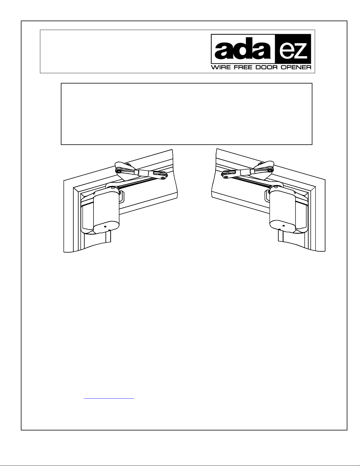
PUSH-SIDE APPLICATION
(LEFT HAND DOOR SHOWN)
This manual provides quick-reference instructions for installing and operating the push-side ADA EZ swing
door operator. Prior to performing these instructions thoroughly review the following information in
document number 70002, “ADA EZ Pro Installation and Operating Instructions:”
System Description
Prerequisites
Precautions
Controls and indicators
Installing the optional plug-in transformer
Installing the pushbutton switches
Linking the RF pushbuttons
• Troubleshooting recommendations
To obtain the latest manual and template revisions or to view installation and programming videos
go to www.ADAEZ.com. For technical support call (877) 232-3987.
700402
Rev. B, 10/30/12
© 2012 ADA EZ. ALL RIGHTS RESERVED.
Detailed operator programming instructions
Replacing the battery pack fuse
Customizing the operator settings
Installing door decals
Detailed closeout instructions
Wiring
Replacement parts
• Adjusting door spring tension
PUSH-SIDE APPLICATION
(RIGHT HAND DOOR SHOWN)
1 of 15
Page 2
Quick-Start Guide
TABLE OF CONTENTS
1.1 Installing the Operator Mounting Template ................................................................................................. 2
1.2 Mounting the Door Arm Pivot Bracket ........................................................................................................ 3
1.3 Installing the Door Arm Pivot ...................................................................................................................... 5
1.4 Installing the Operator Mounting Bracket and Cover .................................................................................. 6
1.5 Installing the Door Arm ............................................................................................................................... 9
1.6 Installing the Optional Plug-In Transformer .............................................................................................. 10
1.7 Programming the Operator......................................................................................................................... 14
1.8 Initializing the Remote Control .................................................................................................................. 15
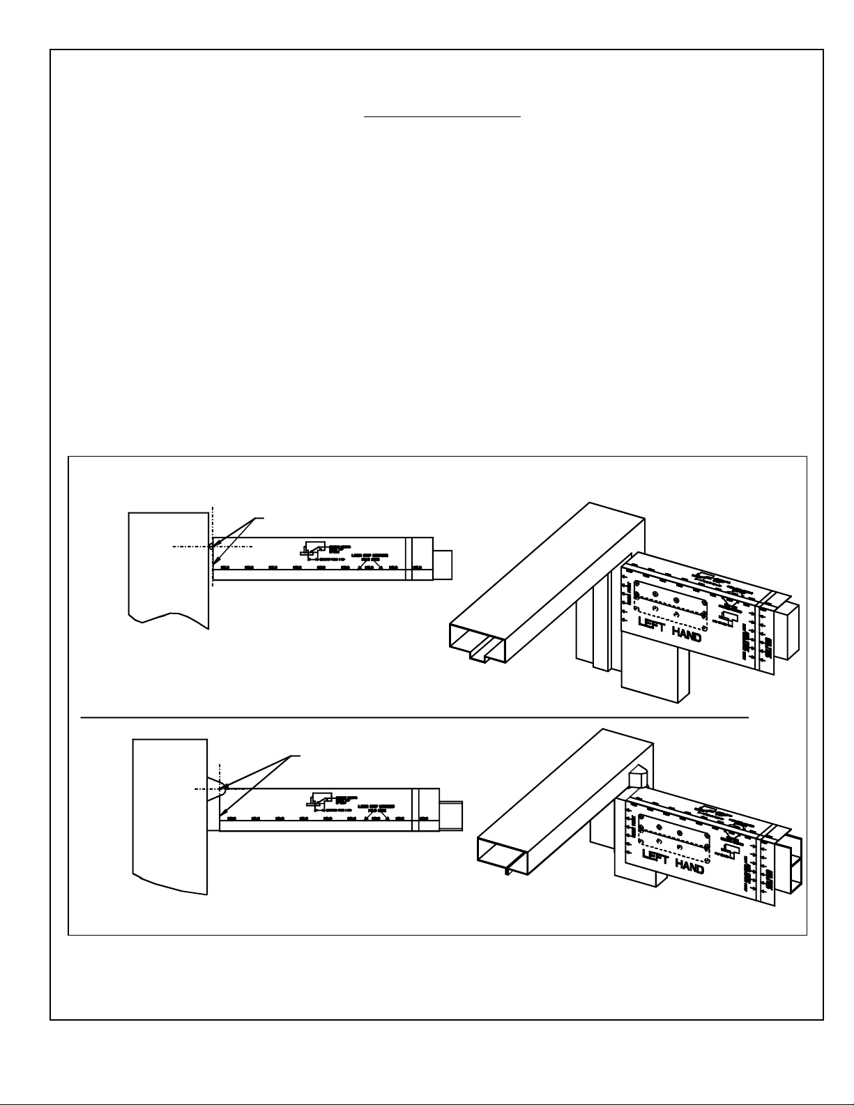
1.1 Installing the Operator Mounting Template
1.1.1 If the door is an aluminum storefront door, EXAMINE the top rail and, when drilling the mounting
holes, ENSURE the following:
• Do not drill into the top rail web
• Do not drill into the rail-to-stile tie rod(s)
• Do not drill into the rail-to-stile junction
1.1.2 Refer to Figure 1, and ALIGN the operator mounting template to the centerline of the butt hinge,
center pivot, or offset pivot as applicable.
Figure 1. Installing the Operator Mounting Template
ALIGN TEMPLATE WITH
HINGE CENTERLINE
TOP VIEW -
BUTT HINGE HUNG DOOR
ALIGN TEMPLATE
WITH PIVOT CENTERLINE
TOP VIEW - OFFSET PIVOT
EZ045
700402
Rev. B, 10/30/12
© 2012 ADA EZ. ALL RIGHTS RESERVED.
2 of 15
Page 3
1.2 Mounting the Door Arm Pivot Bracket
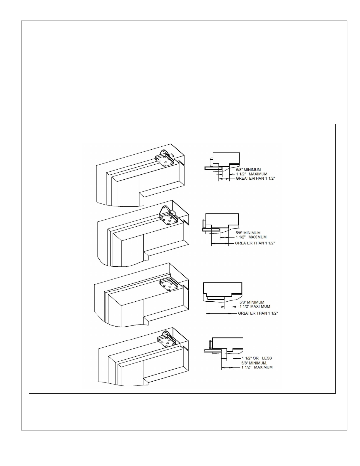
1.2.1 Refer to Figure 2, and DETERMINE the orientation of the door arm pivot bracket as necessary to
ensure the following (as applicable):
• If the door is a typical installation, the vertical support will set flush against the face of the
frame header.
• If the door is a large reveal installation, the bracket will mount to the underside of the frame
header.
• The edge of the bracket will be between 5/8″ (15.87 mm) and 1 1/2″ (38.1 mm) from the face of
door.
Figure 2. Mounting the Door Arm Pivot Bracket
700402
Rev. B, 10/30/12
© 2012 ADA EZ. ALL RIGHTS RESERVED.
3 of 15
Page 4
CAUTION
To ensure proper installation, the door arm pivot bracket must be fastened to the underside of the header
frame and to the face of the header frame with at least three fasteners.
NOTE
When attempting to install the rivnuts to the underside of the door frame it may be necessary to remove the
door stop.
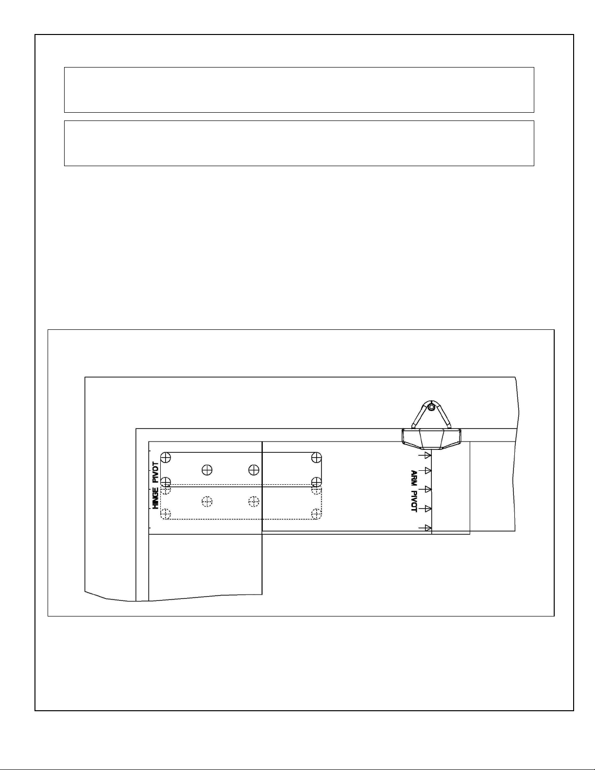
1.2.2 Refer to Figure 3 and, using a center punch, MARK the door arm pivot bracket hole locations.
1.2.3 If the door frame is aluminum and rivnuts must be installed, PERFORM the following:
a. Using a 25/64″ drill, DRILL the door arm pivot bracket holes.
b. Using a rivnut tool, INSTALL the ¼-20 steel rivnuts.
c. INSTALL and TIGHTEN the three (minimum) ¾″ (19.05 mm) socket head capscrews
securing the door arm pivot bracket to the underside and face of the frame header.
1.2.4 If the door frame is wood, PERFORM the following:
a. Using a 5/32″ (3.97 mm) drill, DRILL the door arm pivot bracket pilot holes.
b. INSTALL and TIGHTEN the three #14 x 1 ¼″ wood screws (minimum) securing the door
arm pivot bracket to the underside and face of the frame header.
Figure 3. Mounting the Door Arm Pivot Bracket
700402
Rev. B, 10/30/12
© 2012 ADA EZ. ALL RIGHTS RESERVED.
4 of 15
Page 5
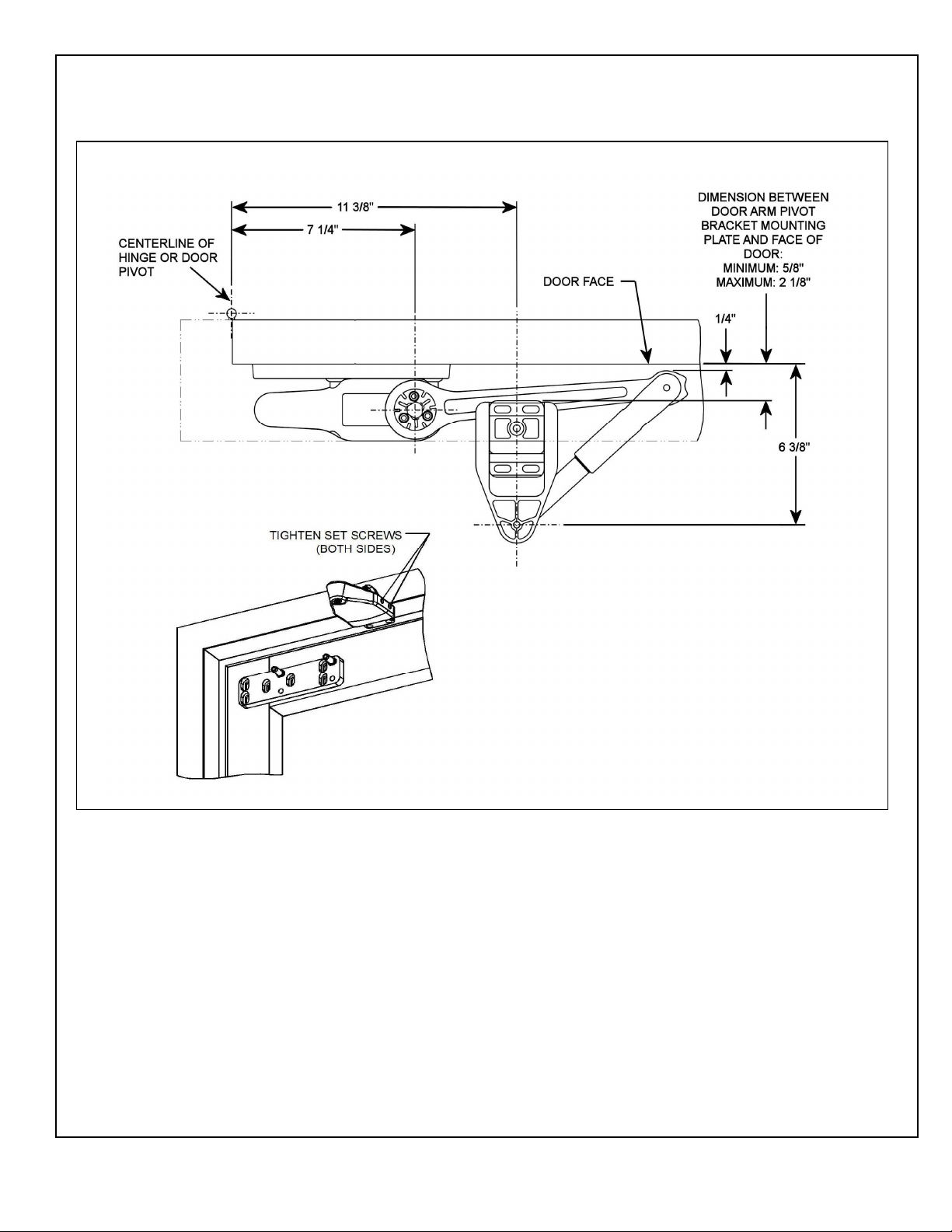
1.3 Installing the Door Arm Pivot
1.3.1 Refer to Figure 4, and SLIDE the door arm pivot over the door arm pivot bracket.
Figure 4. Installing the Door Arm Pivot
1.3.2 ENSURE that the dimension from the face of the door to the centerline of the door arm mounting
hole is 6 3/8″ (161.92 mm).
1.3.3 TIGHTEN the four set screws securing the door arm pivot to the door arm pivot bracket.
700402
Rev. B, 10/30/12
© 2012 ADA EZ. ALL RIGHTS RESERVED.
5 of 15
Page 6
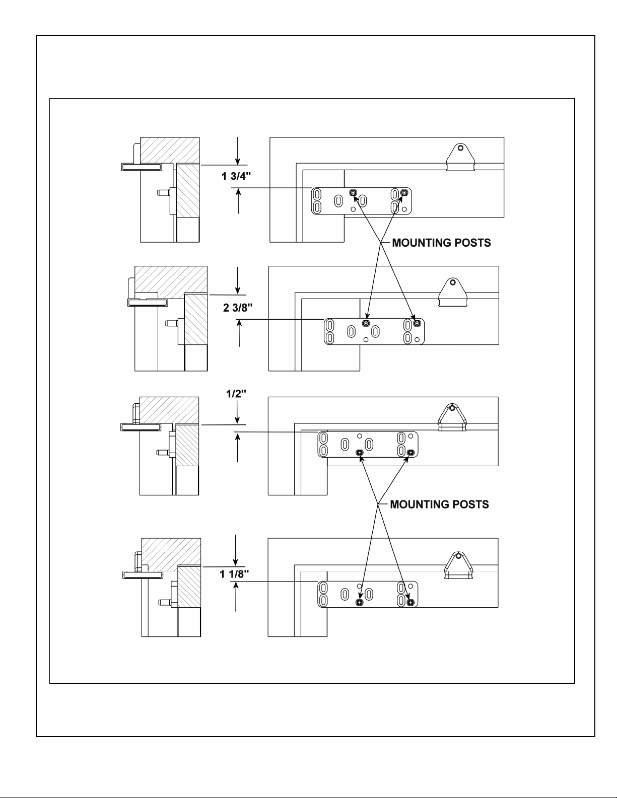
1.4 Installing the Operator Mounting Bracket and Cover
1.4.1 Refer to Figure 5, and DETERMINE the proper operator mounting bracket location.
Figure 5. Determining the Operator Mounting Bracket Location
700402
Rev. B, 10/30/12
© 2012 ADA EZ. ALL RIGHTS RESERVED.
6 of 15
Page 7
1.4.2 If the door frame is aluminum and rivnuts must be installed, PERFORM the following:
• Using a 25/64″ (9.92 mm) drill, DRILL the operator mounting bracket holes.
1.4.3 Using a rivnut tool, INSTALL the ¼-20 steel rivnuts.
NOTE
Some door installations may require sex nut and bolt fasteners.
1.4.4 If the door frame is wood, PERFORM the following:
• Using a 5/32″ (3.97 mm) drill, DRILL the operator mounting bracket holes.
1.4.5 INSTALL a washer onto each of the four (minimum) ¾″ (19.05 mm) socket head operator
mounting bracket capscrews.
1.4.6 INSTALL, but do not TIGHTEN the socket head capscrews securing the operator mounting
bracket to the door.
1.4.7 ADJUST the operator mounting bracket as follows:
• If the upper fold on the operator mounting template was used (large stop mounting), ADJUST
the bracket so that there is 2 3/8″ (60.32 mm) space between the top of the bracket and the top of
the door.
• If the lower fold on the operator mounting template was used (standard mounting), ADJUST
the bracket so that there is 1¾″ (44.45mm) space between the top of the bracket and the top of
the door.
• If the narrow stile door mounting location was used (solid line on operator mounting template),
ADJUST the bracket so that there is 1/2″ (12.7 mm) space between the top of the bracket and
the top of the door.
1.4.8 TIGHTEN the socket head capscrews securing the operator mounting bracket to the door.
NOTE
The operator mounting bracket includes four threaded holes that accept the operator mounting pins. The
lower set of two threaded holes is used when the operator is installed on a narrow-rail door. The upper set
of two threaded holes is used when the operator is installed on a medium- or wide-rail door.
1.4.9 Refer to Figure 5 and PERFORM one of the following as applicable:
• If the operator is being mounted to a narrow rail door, TIGHTEN the operator mounting pins
into the lower threaded holes in the mounting bracket using a 7/16″ (11.112 mm) box wrench or
large adjustable wrench.
• If the operator is being mounted to a wide or medium rail door, TIGHTEN the operator
mounting pins into the upper threaded holes in the mounting bracket using a 7/16″ (11.112 mm)
box wrench or large adjustable wrench.
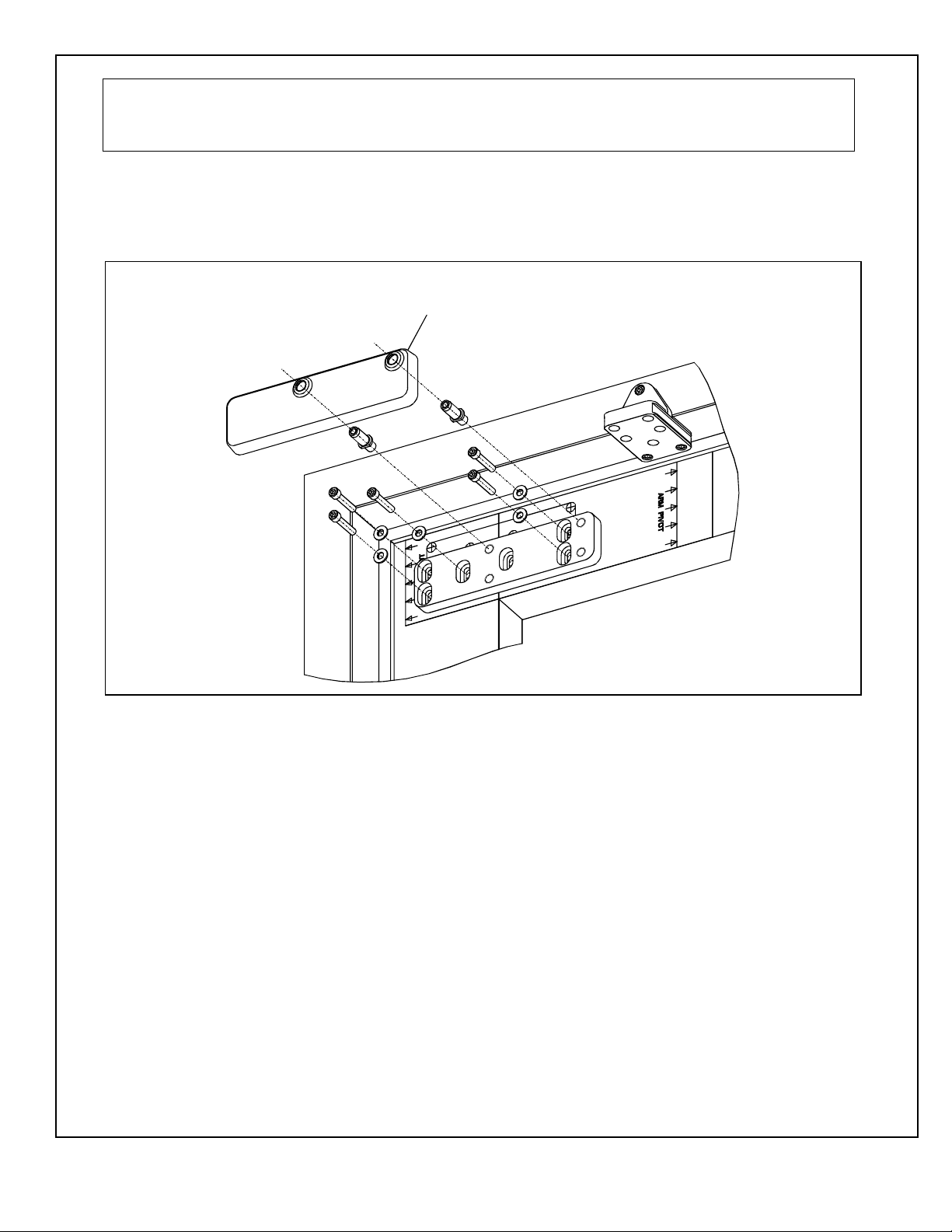
1.4.10 Refer to Figure 6, and INSTALL the operator mounting bracket cover over the operator mounting
bracket.
1.4.11 REMOVE the two capscrews securing the operator bottom cover to the operator.
1.4.12 REMOVE the bottom cover from the operator.
1.4.13 SLIDE the battery pack from the operator and REMOVE the battery pack.
1.4.14 REMOVE the dress cover from the operator.
700402
Rev. B, 10/30/12
© 2012 ADA EZ. ALL RIGHTS RESERVED.
7 of 15
Page 8
WARNING
To avoid inadvertent activation of the operator during connection of the door arm, the battery pack should
not be installed until after the door arm is connected.
1.4.15 With the battery pack facing the jamb, POSITION the operator onto the operator mounting pins.
ENSURE the operator does not slide off the mounting pins.
1.4.16 INSTALL and TIGHTEN the two ¼-20 X 1½″ socket head capscrews securing the operator to the
operator mounting pins.
Figure 6. Installing Operator Mounting Bracket Cover
OPERATOR MOUNTING
BRACKET COVER
EZ021
700402
Rev. B, 10/30/12
© 2012 ADA EZ. ALL RIGHTS RESERVED.
8 of 15
Page 9
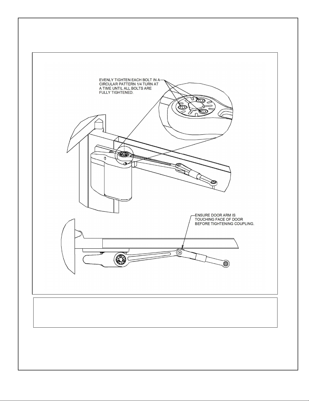
1.5 Installing the Door Arm
1.5.1 Refer to Figure 7, and, with the door arm coupling screws facing up and the door arm against the
door rail, POSITION the larger end of the door arm onto the operator output shaft.
Figure 7. Installing the Door Arm
CAUTION
The door arm coupling is a two-piece tapered coupling. In order to draw the coupling halves together
evenly the three door arm coupling screws must be tightened evenly (one quarter turn at a time) until fully
tight.
1.5.2 With the door arm touching the face of the door, TIGHTEN the door arm coupling screws evenly
(one quarter turn at a time) until fully tight.
700402
Rev. B, 10/30/12
© 2012 ADA EZ. ALL RIGHTS RESERVED.
9 of 15
Page 10
1.5.3 HOLD the elbow of the door arm against the face of the door, and THREAD the adjustable door
arm end link into the door arm as necessary to align the end link mounting hole with the door arm
pivot mounting hole.
1.5.4 If the door arm end link does not align with the door arm pivot mounting hole and there is no
available travel on the threaded end link, PERFORM the following:
• LOOSEN the socket head capscrews securing the door arm pivot to the door arm pivot bracket.
• SLIDE the door arm pivot as necessary to align the door arm end link with the door arm pivot
mounting hole.
• TIGHTEN the socket head capscrews securing the door arm pivot to the door arm pivot
bracket.
NOTE
In order to apply a preload to the door, the door arm must be threaded into the door arm three revolutions.
1.5.5 THREAD the adjustable door arm end link into the door arm three revolutions.
1.5.6 INSTALL the washer provided onto the top of the door arm end link, and TIGHTEN the 5/16 -18 X
7
/8″ button-head capscrew securing the door arm end link to the door arm pivot bracket.
1.5.7 CYCLE the door several times, and ENSURE that the door opens and closes smoothly.
1.5.8 SLIDE the dress cover onto the operator.
1.5.9 CONNECT the battery pack connector plug to the operator.
1.5.10 SLIDE the battery pack onto the operator, and ENSURE that the battery pack wires will not
interfere with the operator cover.
1.6 Installing the Optional Plug-In Transformer
NOTE
If possible, the transformer wiring should be routed against the door trim molding.
1.6.1 ROUTE transformer wiring to a 110-VAC outlet, but do not plug transformer into the outlet.
NOTE
An optional plug-in transformer is recommended in installations where the automatic door-opening feature
will be used frequently. The optional plug-in transformer is REQUIRED for installations where Power
Close and/or Push and Go features are enabled.
1.6.2 Refer To Figure 8, and ROUTE wires through armored cable end links. MOUNT the door cord end
links as follows:
• MOUNT one end link in the area behind or next to the battery pack.
• MOUNT the other end link on or next to the door frame.
700402
Rev. B, 10/30/12
© 2012 ADA EZ. ALL RIGHTS RESERVED.
10 of 15
Page 11
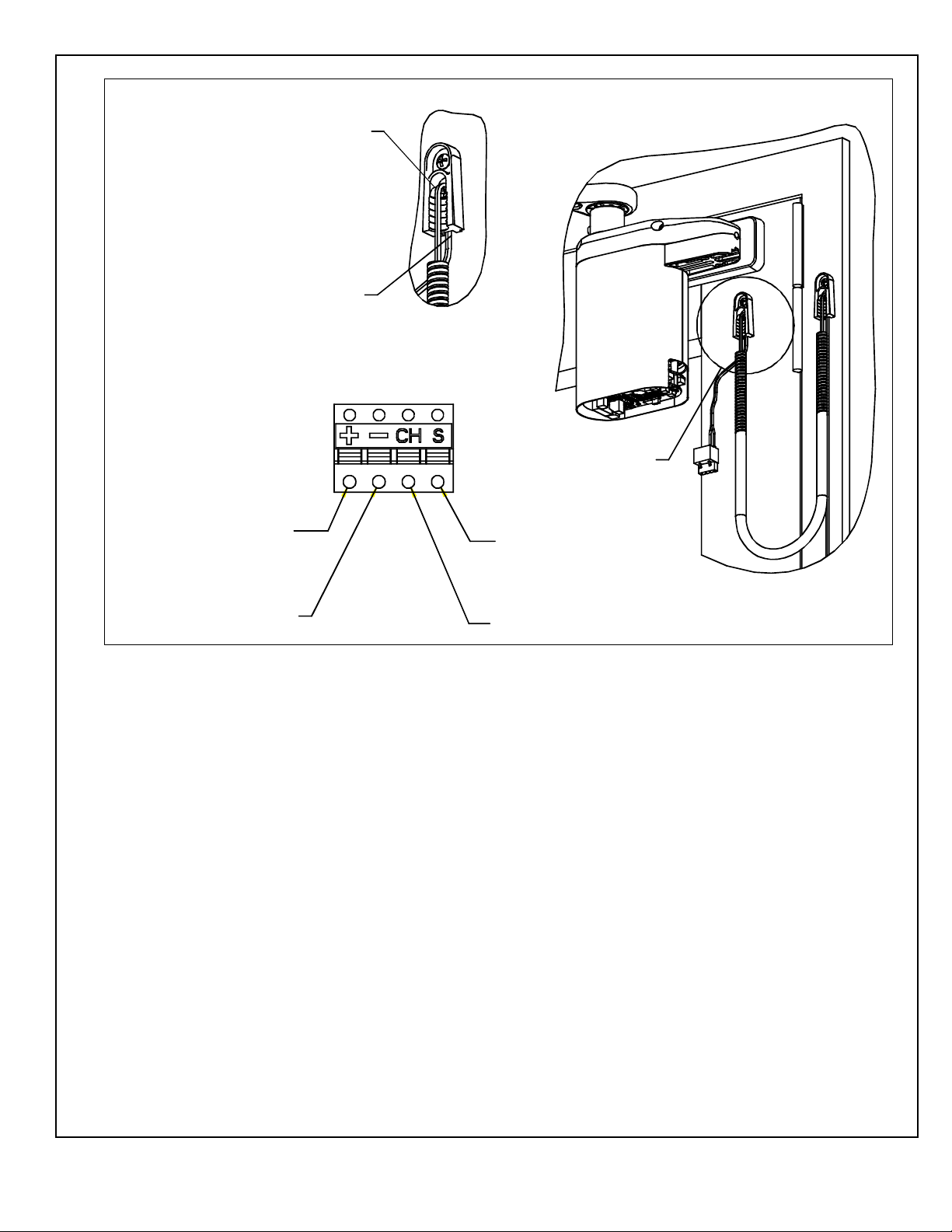
Figure 8. Routing Wires through Cable End Links
ROUTE WIRE INTO
END LINK FROM
FRONT
ROUTE WIRE THROUGH
EXIT AT BOTTOM
DETAIL A
SEE DETAIL A
24VDC (POSITIVE) INPUT
GROUND (COMMON) INPUT
SIGNAL INPUT
CHARGER INPUT
EZ061
700402
Rev. B, 10/30/12
© 2012 ADA EZ. ALL RIGHTS RESERVED.
11 of 15
Page 12
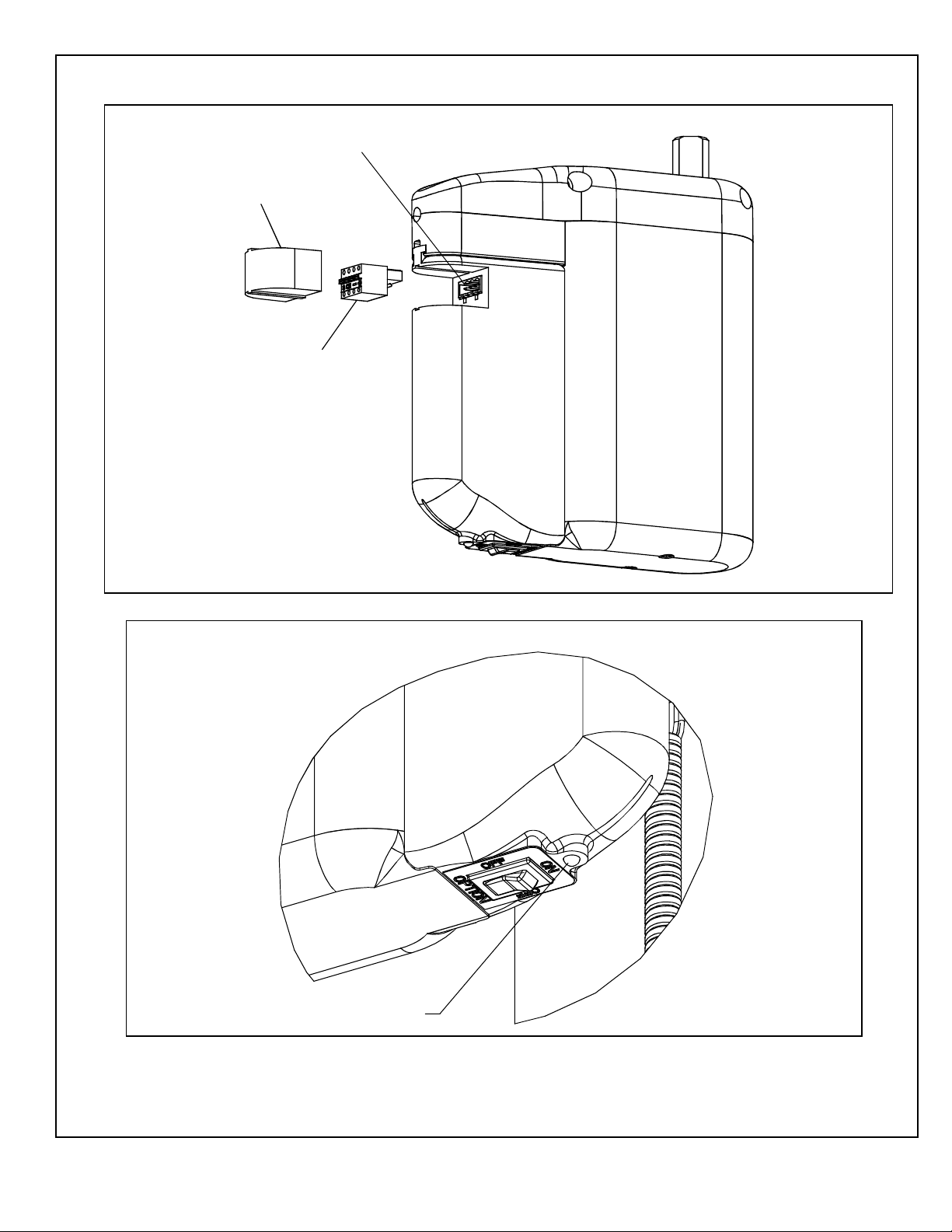
1.6.3 Refer to Figure 9, and PLUG connector into receptacle on battery pack.
Figure 9. Plugging the Connector into the Receptacle
CONNECTOR RECEPTACLE
CONNECTOR COVER
CONNECTOR PLUG
1.6.4 Refer to Figure 10, and VERIFY that the LED indicator lights GREEN.
Figure 10. Verifying that the LED Illuminates
LED INDICATOR
ADAEZ60
EZ060
700402
Rev. B, 10/30/12
© 2012 ADA EZ. ALL RIGHTS RESERVED.
12 of 15
Page 13
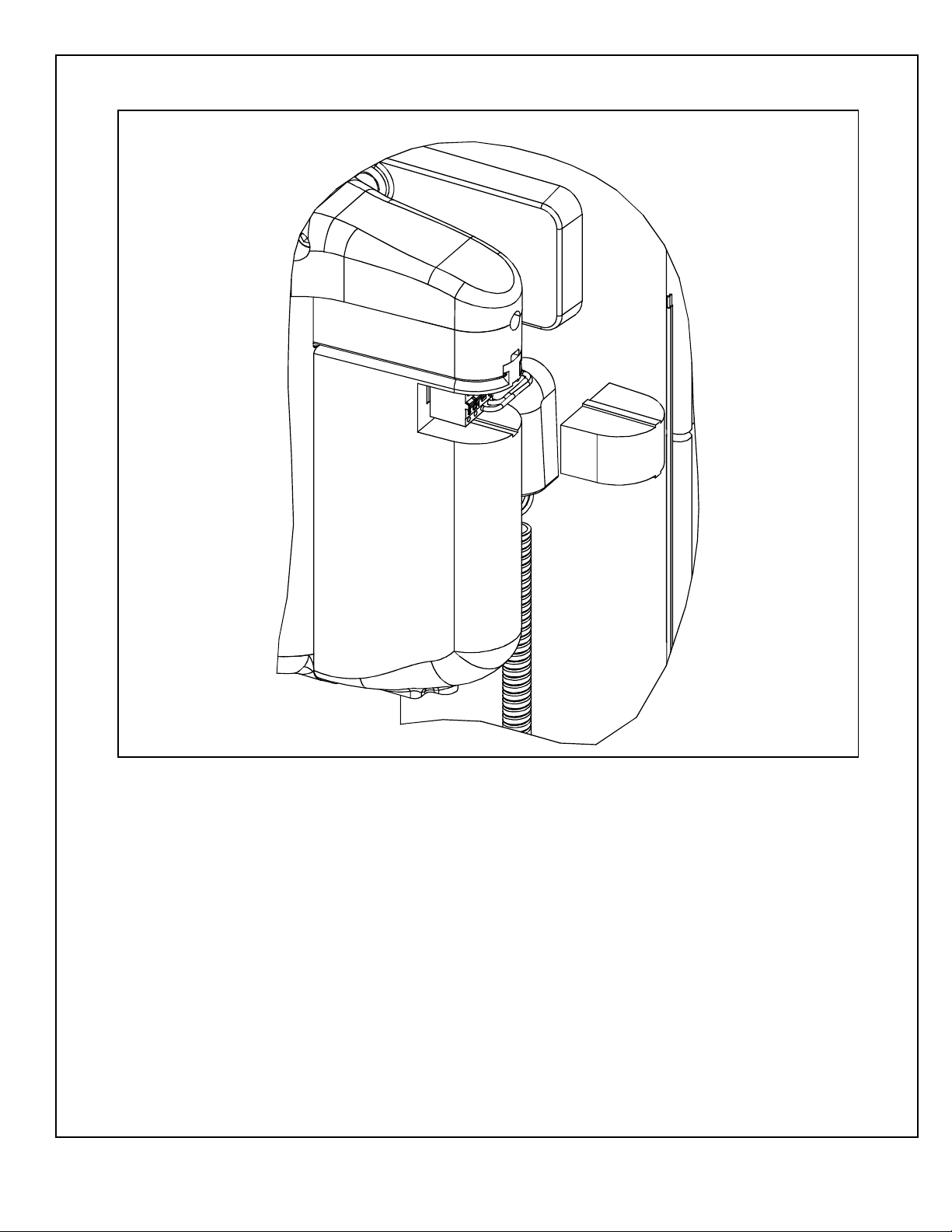
1.6.5 Refer To Figure 11, and INSTALL receptacle cover onto battery pack.
Figure 11. Plugging the Receptacle Cover onto the Battery Pack
EZ062
700402
Rev. B, 10/30/12
© 2012 ADA EZ. ALL RIGHTS RESERVED.
13 of 15
Page 14
1.7 Programming the Operator
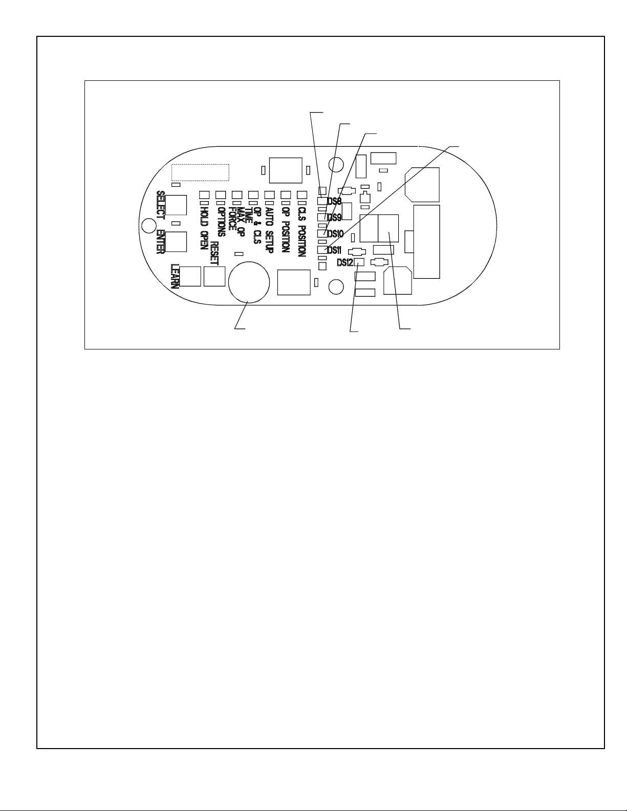
Figure 12. Door Controller Circuit Board Controls and Indicators
ADJUSTMENT INDICATOR LEDs
DS8 POWER CLOSE LED
DS9 PUSH AND GO LED
DS10 DYNAMIC BRAKING LED
DS11
TUNING POTENTIOMETER
DS12
TERMINAL BLOCK FOR
OPTIONAL TRANSFORMER
ADAQS07A
1.7.1 Refer to Figure 12, and, at the base of the controller, PRESS and HOLD the “SELECT” and
“ENTER” pushbuttons for three seconds. The following shall occur:
• The operator shall enter program mode.
• The four LEDs on the circuit board shall repeatedly flash green.
• The “CLS” position LED shall illuminate red and remain lit.
1.7.2 With the door in the closed position, PRESS the “ENTER” pushbutton. The following shall occur:
• The “CLS” position LED shall flash green.
• The “OP” (open) position LED shall illuminate red indicating that the operator is ready for
input.
• The LED shall illuminate green once data has been stored for this parameter.
1.7.3 With the door in the closed position, PRESS the “ENTER” pushbutton.
1.7.4 OPEN the door to its fully open position.
1.7.5 With the door in the fully open position, PRESS the “ENTER” pushbutton. The following shall
occur:
• The “OP” position LED shall flash green.
• The “AUTO SETUP” position LED shall illuminate red indicating that the operator is ready for
input.
• The LED shall illuminate green once data has been stored for this parameter.
1.7.6 With the door in the fully closed position, PRESS the “ENTER” pushbutton. The following shall
occur:
700402
Rev. B, 10/30/12
© 2012 ADA EZ. ALL RIGHTS RESERVED.
14 of 15
Page 15

• The door shall open quickly and then close.
• The “AUTO SETUP” led shall illuminate green.
1.7.7 PRESS and HOLD the “ENTER” pushbutton for three seconds. The following shall occur:
• The “AUTO SETUP” led shall go out.
• The second LED (not labeled) shall flash green.
• The door shall be tuned.
1.7.8 To reset the controller, PERFORM the following:
a. PRESS and HOLD the “RESET” pushbutton.
b. PRESS and HOLD the “ENTER” pushbutton.
c. RELEASE the “RESET” pushbutton.
1.7.9 If further door adjustments are necessary, refer to document number 70001, “ADA EZ Installation
and Operating Instructions,” and ADJUST as needed.
1.8 Initializing the Remote Control
1.8.1 To link an RF switch with a door controller, PERFORM the following:
a. PRESS and HOLD the “LEARN” pushbutton on the controller until LEDs DS8 through DS11
flash green. The controller shall remain in the learn mode for 20 seconds or until the RF signal
is received.
b. PUSH the RF pushbutton. LED DS7 shall flash green indicating that the operator accepted this
RF pushbutton.
c. REPEAT steps 1.8.1.a. and 1.8.1.b. as necessary for up to eight ADA EZ transmitters.
1.8.2 To remove all RF pushbuttons from memory, PERFORM the following:
a. While pressing and holding the “LEARN” pushbutton on the controller, PRESS and
RELEASE the “RESET” pushbutton.
700402
Rev. B, 10/30/12
© 2012 ADA EZ. ALL RIGHTS RESERVED.
15 of 15
 Loading...