

Page 1
DIGITAL BLUETOOTH THEROMETER
PBT
Page 2

Index
1.
Introduction
2.
Important Information Before Use
3.
Product Identification
4.
Description of LCD Display
5.
Battery Installation
6.
Changing Modes (°C/°F Switchable)
7.
Tips for Measuring HumanTemperature
8.
Measuring Body Temperature in the Ear
9.
Memory Function
10.
Operating The Bluetooth Function
11.
Care and Maintenance
12.
Applied Standards
13.
Error Codes
14.
Technical Specifications
15.
FCC Statement
16.
EMC Tables
1
2
3
3
4
5
6
7
10
11
14
14
15
15
16
18
Page 3

Introduction
Utilizing infrared technology, this thermometer takes
temperatures in seconds by measuring heat
generated by the ear canal or other objects .This
directive MDD(93/42/EEC).Its advantages include:
1. Wireless communication : Bluetooth (class 2)
2. Intended use: For home, clinic, and hospital use to
determine human body temperature.
3. Illuminated back-light display
4. 10 user memory
5. °C/°F switchable f unction
6. Probe cover free
7. Waterproof probe design
8. One-second reading
9. Auto power off for power saving
10. Low-battery i ndicator
11. War ning indication for battery condition and
measuring range.
12. Large LCD display
product conforms to the provisions of the EC
1
Page 4

Important Information Before Use
When using this product, please be sure to follow all the
notes listed below.Any action against these notices may
cause injury or affect the accuracy.
1. Do not disassemble, repair, or remodel the
thermometer.
2. Be sure to clean the thermometer l ens each time after
usage.
3. Avoid direct finger contact with the lens.
4. No modification of this equipment is allowed.
5. It is recommended that user take 3 temperatures. If
they are different,use the average reading.
6. Do not expose the thermometer to extreme
temperature, very high humidity, or direct sunlight.
7. Avoid extreme shock or dropping the device.
8. Before the measurement, patients and t hermometer
should stay in steady state room condition for at least
30 minutes.
9. Avoid measuring temperature in 30 minutes after
exercise, bathing, or returning from outdoor.
10. To protect the environment, dispose of empty batteries
at a ppropriate collection sites according to national or
local r egulations.
11. Please use the thermometer solely forits intended
purpose.
Carefully hold the device when in use to avoid dropping
12.
the device.
13.
Allow one minute between successive measurements
as s light variations may occur if measurements are
taken over a short period of time. Use average
temperatures instead.
There are no absolute body temperature standards.
14.
Keep reliable records of your personal temperature to
serve as a reference for judging a fever.
Under any circumstances, the temperature taking
15.
result is ONLY for reference. Before taking any medical
action, p lease consult your physician.
2
Page 5
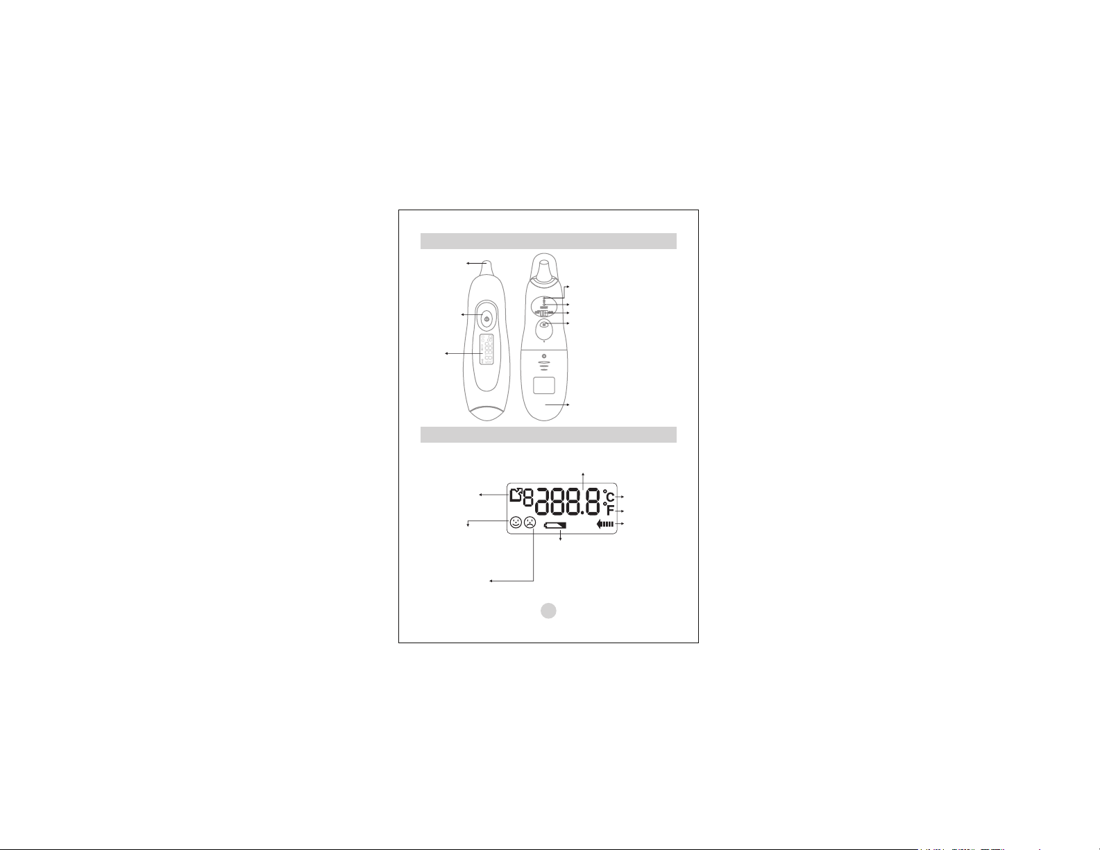
Product Identification
Probe Tip
Power &
Measure
Button
LCD
Display
Description of LCD Display
Memory Symbol
and Sets of
Records
Smiling face
Indicating temperature
is lower than
38°C (100.4°F)
Frowning face
Indicating temperature
is equal or higher than
38°C (100.4°F)
LED (Wireless
connecting indicator)
Wireless Reset Key
Wireless Power Button
MEMORY
Recall
Button
Battery
compartment
lid
Degrees of
Temperature
Low battery
Warning
3
Celsius
Scale
Fahrenheit
Scale
Scan in
Progress
Page 6
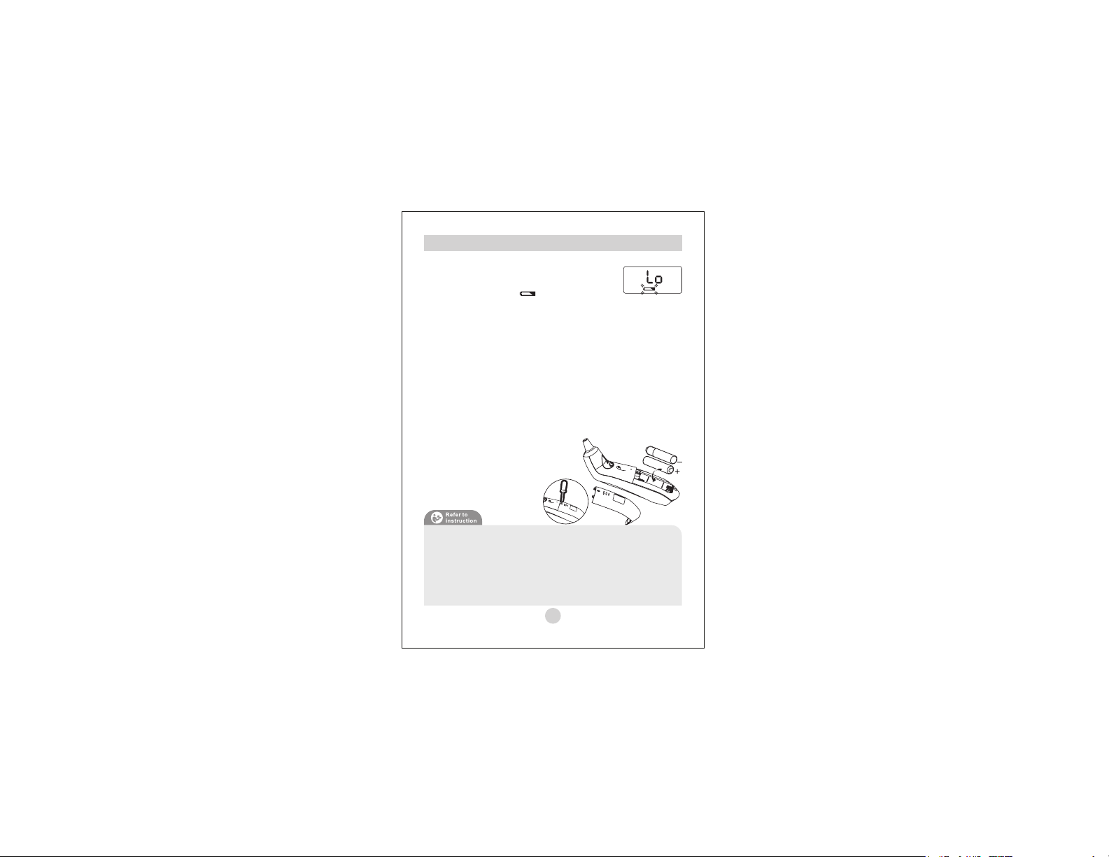
Battery Installation
Low battery warning:
When the battery power becomes low, the
low battery symbol “”will appear on
the display.The thermometer can still be used during
this time, but the batteries should be replaced as soon
as possible. If the batteries run out completely,“Lo”
will be displayed along with the low battery symbol. In
this case, the batteries will need to be replaced before
using the thermometer again.
Replacing the Battery:
1. Use a Phillips head screwdriver to loosen battery
cover screw. Remove the battery cover.
2. Insert or replace 2 x 1.5 V AAAalkaline batteries into
the battery compartment, ensuring to match the
indicated polarity symbols.Always use new
batteries.
3. Place the battery cover on the
thermometer and tighten the
screw to secure it in place.
Battery-operated
1. Please properly dispose of the batteries away from
small children and heat.
2. It is recommended to remove the batteries if the
unit will not be used for an extended period of time.
3. Batteries must be disposed of in accordance with
local environmental and institutional policies.
4
Page 7

Changing Modes (°C/°F Switchable )
This thermometer can display result in either degrees
Fahrenheit(°F) or degrees Celsius(°C).
Changing °C/ °F, p lease make sure the device is in
power on condition. Press the Power/Scan button,
hold it, and then press the Memory button to toggle
between °C and °F.
5
Page 8

Tips for Measuring Human Temperature
Bear in mind that the thermometer needs to have been
in the room in which the measurement is taken for at
least 30 minutes before use.
•Some people produce different readings in their left
and right ear. In order to record temperature
changes, always measure a person’s temperature in
the same ear.
•The ear thermometer may be used by children only
under adult supervision. Measurement is usually
possible over the age of 6 months. In infants under 6
months, the ear canal is still very narrow so the
temperature of the eardrum often cannot be recorded
and the result displayed is often too low.
•The measurement must not be taken in an ear
affected by inflammatory diseases (e.g. discharging
pus or secretion), after possible ear injuries (e.g.
eardrum damage) or in the healing period after
operative procedures. In all of these cases, please
consult your doctor.
•Use of the thermometer on different persons can be
inappropriate in the event of certain acute infectious
diseases because of the possible spread of germs
despite cleaning and disinfection. If you have any
doubts, please consult your doctor.
•This thermometer may only be used without a
disposable protective cover.
•If
you have been lying on one ear for some time, the
temperature is slightly raised. Wait a little while or
measure in the other ear.
•As ear wax can affect the measurement, you should
clean the ear before measuring if necessary.
6
Page 9

Measuring Body Temperature in the Ear
1. Remove the front cover: Remove the cover cap:
Remove the cap by gently pushing it up (1) and then
pulling it off forwards (2).
2. Press the Power button to switch the thermometer
on. Following a successful self test, the device
emits two short beeps.
3. Make sure that the sensor tip and also the ear canal
are clean. As the ear canal is slightly curved, you
have to pull the ear slightly up and backwards
before inserting the sensor tip. This is important so
that the sensor tip can be pointed directly at the
eardrum.
4. Insert the probe into the ear canal (the probe must
insert well to ensure an accurate temperature
measurement), then press the “Power & Measure”
button for about 1 second, release the button and
you will hear 1 short beep sound means complete
the measurement.
7
Page 10

Measuring Body Temperature in the Ear
• Under 1 year:
Have child lay flat with the head
sideways, so that the ear is facing
upwards. Gently pull the ear straight
back.
•1 year +:
Stand behind and slightly to the side of
the child/adult. Gently pull the ear up
and back to straighten the ear canal.
5. You may take out the device to read the
measurement result.
6. The backlight display will remain light for
approximately 5 seconds each time the “Power &
Measure” button is pressed, after each reading is
completed, and each time the “Memory” button is
pressed to recall a previous reading.
7. The thermometer will automatically shut off after
one minute without use.
1. To ensure accuracy, please w ait at least 20
seconds between successive readings.
2. Clean the thermometer lens again after use.
Wait at least10 minutes between consecutive
readings, to ensure accuracy.
8
Page 11

Measuring Body Temperature in the Ear
The Readings:
If the temperature measurement is
below 38°C, a “Smiling Face ”
will be appear next to the reading.
If the reading is 38°C or above, a
“Frowning Face ” will be
displayed.
9
Page 12

Memory Function
Memory Recall:
You can recall up to 10 measurements of all currently
stored measurements in memory to share with your
physician or trained healthcare professional.
1. While in power on mode, press once briefly on the
“Memory” button, then pass it a gain to show the last
measurement accompanied by “”symbol.
2. Continue to press the “Memory” button to view the
next previously stored measurement, so “”
then all the way to “”.
3. Automatically on the 11th measurement: when the
10 memories have been used up, any new
measurement will be recorded and the oldest
memory deleted.
10
Page 13

Operating The Bluetooth Function
1. Turn the ear thermometer to the back side.
2. Turn on the wireless power (From "off" to "on"),
while the thermometer searches for other Bluetooth
compatible devices, the LED (connection indicator)
will flash. When the device connects successfully to
health monitoring devices and Bluetooth-capable
devices, such as a computer, PDA, or mobile phone,
the LED will remain lit.At conclusion of temperature
measurement, the reading will be sent to the health
monitoring device and the reading will automatically
stored in memory.
3. To disconnect from health monitoring devices, turn
off the wireless power (From "on" to "off"), and the
LED will no longer be lit.
11
Page 14

Operating The Bluetooth Function
WhatYou Need:
The host computer or terminal system to run Serial
Port Profile (SPP)
-Apersonal computer with Operating system:
Windows 95 or later
-ASmart Phone withAndroid system
- Others: PDA, etc.
Please refer to the instruction manual of your
personal computer for how to install Serial Port
Profile (SPP).
Bluetooth LED:
FAST BLINKING: indicate this UT-302 PBT is at linking
state waiting be linked by other Bluetooth terminal
system like Smart Phone.
SLOW B LINKING: indicate is waiting for
connection from other m aster B luetooth device.
ACTIVE: indicate Bluetooth c onnection h ave b een
established successfully
to
UT-302 PBT
12
Page 15

Operating The Bluetooth Function
Communications Interface:
Using Bluetooth communications terms, the
UT-302PBT is a slave device. To connect the UT-302PBT
to a master device you must initiate the connection by
first pairing with the UT-302PBT. To complete the pairing
process the “0000” number must be provided to the
master as the Bluetooth Pass Key (Bluetooth PIN Code).
Once the pairing is complete the UT-302PBT will
automatically reconnect to the master device when
possible. The four digit Bluetooth Pass Key must be
entered only during the pairing to a new master
To connect to a new device (new master) the
UT-302PBT
master or unpaired from that master
must be out of range from the previous
13
.
Page 16

Care and Maintenance
Probe and Tip:
•
Clean the probe and tip with an
alcohol swab before and after
each measurement.
Thermometer:
•
Use a soft, dry cloth to clean
thermometer body. Never use
abrasive cleaning agents, thinners or
benzene for cleaning. Do not scratch
the surface of the probe lens or the
display. Do not expose the
thermometer to extreme
temperatures, humidity, direct
sunlight, or shock.
Applied Standards
This product conforms to the provisions of the EC
directive MDD (93/42/EEC).The following standards
apply to design and/or manufacture of the products:
. E N12470- 5
Clinical thermometers-Part 5: Performance of infrared earThermometers (with maximum device)
.AST M E 1965-98
Standard Specification for Infrared Thermometers for Intermittent Determination of Patient
Temperature.
.
IEC/EN 60601-1
Medical electrical equipment-Part1: General requirements for safety.
. IEC/EN 60601-1-2
Medical electrical equipment-Part2: Collateral standard: Electromagnetic compatibilityRequirements and tests.
14
Page 17

Error Codes
When a malfunction or incorrect temperature measurement occurs,
an error message will appear as described below.
LCD Display Cause Solution
Operate the thermometer
The temperature measured is
lower than 34°C (93.2°F)
The temperature measured is
higher than 43°C (109.4°F)
The operating temperature is
not in the range from
16°C~35°C (60.8°F~95.0°F)
only between the
specified temperature
ranges. If necessary,
clean the sensor tip. In
the event of a repeated
error message, contact
your retailer or Customer
Services.
Operate the thermometer
only between the
specified temperature
ranges.
Technical Specifications
• 34°C~43°C (93.2°F~109.4°F)
Measuring range:
•
Measuring accuracy
35.5°C~42°C (95.9°F~107.6°F):
outside the range:
•
Operating environment:
oo oo
16 C~35 C (60.8F~95F)
with relative humidity up to 85% (non condensing)
•
Storage/ Transportation environment:
oooo
-25C~+55C (-13F~+131 F)
with relative humidity up to 85% (non condensing)
• 0.1 C or F
Display resolution:
• 2 x 1.5 V AAAalkaline batteries
Power supply:
• approx. 70g (without batteries)
We ight :
• approx. x x (L x W x H)
Dimensions :
:
6.2in 1.7in 2.1in
oo
±0.2°C(0.4°F)
±0.3°C(0.5°F)
15
Page 18

FCC Statement
This equipment has been tested and found to comply
with the limits for a Class B digital device, pursuant to
Part 15 of the FCC Rules.
These limits are designed to provide reasonable
protection against harmful interference in a residential
installation.
This equipment generates, uses, and can radiate radio
frequency energy and, if not installed and used in
accordance with the instructions, may cause harmful
interference to radio communications. However, there
is no guarantee that interference will not occur in a
particular installation. If this equipment does cause
harmful interference to radio or television reception,
which can be determined by turning the equipment off
and on, the user is encouraged to try to correct the
interference by one of the following measures:
1. Reorient or relocate the receiving antenna.
2. Increase the separation between the equipment and
receiver.
3. Connect the equipment into an outlet on a circuit
different from that to which the receiver is
connected.
4. Consult the dealer or an experienced a udio/TV
technician for help.
5. FCC Caution: To assure continued compliance,
(example–use only shielded interface cables when
connecting to computer or peripheral devices). Any
changes or modifications not expressly approved by
the party responsible for compliance could void the
user’s authority to operate this
equipment.
16
Page 19

FCC Statement
6. This device complies with Part 15 of the FCC Rules.
Operation is subject to the following two conditions:
(1) this device may not cause harmful interference,
and (2) this device must accept any interference
received, including interference that may cause
undesired operation.
7. This device complies with FCC radiation exposure
limits set forth for an uncontrolled environment. End
users must follow the specific operating instructions
for satisfying RF exposure compliance. This
transmitter must not be co-located or operating in
conjunction with any other antenna or transmitter.
17
Page 20

EMC Tables
Guidance and manufacturer's declaration-electromagnetic emission
UT-302PBT is
The intended for use in the electromagnetic environment specified
Thermometer
below.The customer or the user of the should assure that it is used
in such an environment.
Emissions test Compliance Electromagnetic environment guidance
RF emissions CISPR 11 Group 1The uses RF energy only
RF emissions
CISPR 11
Harmonic
emissions
IEC 61000-3-2
Voltage
fluctuations/
flicker emissions
IEC 61000-3-3
The is intended for use in the electromagnetic environment specified
below.The customer or the user of the should assure that it is used
in such an environment.
Immunity test
Electrostatic
discharge (ESD)
IEC 61000-4-2
Power frequency
(50/60 Hz)
magnetic field IEC
61000-4-8
Class B
Not
applicable
Not
applicable
Guidance and manufacturer's declaration-electromagnetic immunity
Thermometer
UT-302PBT
IEC 60601
test level
± 6 kV
contact
± 8 kV air
3A/m 3A/m Power frequency magnetic fields should be at
UT-302PBT
Thermometer
Thermometer
UT-302PBT
for its internal function. Therefore, its RF emissions are very
low and are not likely to cause any interference in nearby
electronic equipment.
Thermometer
The is suitable for use in all
UT-302PBT
establishments, including domestic establishments and
those directly connected to the public low-voltage power
supply network that supplies buildings used for domestic
purposes.
Thermometer
UT-302PBT
Compliance
± 6 kV
contact
± 8 kV air
Electromagnetic environment-guidance
level
Floors should be wood, concrete or ceramic
tile. If floors are covered with synthetic
material, the relative humidity should be at
least 30 %.
levels characteristic of a typical location in a
typical.
18
Page 21

EMC Tables
Guidance and manufacturer's declaration-electromagnetic immunity
UT-302PBT
The is intended for use in the electromagnetic environment
Thermometer
specifiedbelow. The customer or the user of the should assure that
it is used in such an environment.
Immunity
IEC 60601 test
test
Radiated
3 V/m
RF IEC
80 MHz to 2,5
61000-4-3
GHz
NOTE 1.
At 80 MHz and 800 MHz, the higher frequency range applies.
NOTE 2.
These guidelines may not apply in all situations. Electromagnetic propagation is
affected by absorption and reflection
a. Field strengths from fixed transmitters, such as base stations for radio (cellular/cordless)
telephones and land mobile radios, amateur radio,AM and FM radio broadcast andTV
broadcast cannot be predicted theoretically with accuracy.To a ssess the electromagnetic
environment due to fixed RF transmitters, an electromagnetic site survey should be
considered. If the measured field strength in the location in which the
Thermometer
Thermometer
observed, additional measures may be necessary, such as reorienting or relocating the
Thermometer.
UT-302PBT
b. Over the frequency range 150 kHz to 80 MHz, field strengths should be less than 3 V/m.
Compliance
level
l
3 V/mPortable and mobile RF communications equipment
is used exceeds the applicable RF compliance level above, the
should be observed to verify normal operation. If abnormal performance is
UT-302PBT
Thermometer
Electromagnetic environment-guidance
evel
should be used no closer to any part of the
Thermometer
, including cables, than the
recommended separation distance calculated from
the equation applicable to the frequency of the
transmitter.
Recommended separation distance
√
d=1.2P
√
d=1.2P80 MHz to 800 MHZ
√
d=2.3P800 MHz to 2,5 Ghz
where Pis the maximum output power rating of the
transmitter in watts (W) according to the transmitter
manufacturer and d is the recommended separation
distance in metres (m).
Field strengths from fixed RF transmitters, as
determined by an electromagnetic site survey-a,
should be less than the compliance level in each
frequency range-b.
Interference may occur in the vicinity of equipment
marked with the following symbol:
from structures, objects and people.
19
UT-302PBT
UT-302PBT
UT-302PBT
Page 22

EMC Tables
Recommended separation distances between portable and mobile RF communications
The monitor is intended for use inan e lectromagnetic environment
UT-302PBT
in which radiated RF disturbances are controlled.The customer or the user of the
Thermometer
distance between portable and mobile RF communications equipment (transmitters) and the
Thermometer
UT-302PBT
the communications equipment.
Rated maximum
output power of
transmitter
W
0.01
0.1
1
10
100
For transmitters rated at a maximum output power not listed above, the recommended
separation distance d in metres (m) can be estimated using the equation applicable to the
frequency of the transmitter, where Pis the maximum output power rating of the transmitter in
watts (W) according to the transmitter manufacturer.
NOTE 1.
At 80 MHz and 800 MHz, the separation distance for the higher frequency range
applies.
NOTE 2.
These guidelines may not apply in all situations. Electromagnetic propagation is
affected by absorption and reflection from structures, objects and people.
equipment and the Thermometer
Thermometer
can help prevent electromagnetic interference by maintaining a minimum
as recommended below, according to the maximum output power of
Separation distance according to frequency of transmitter
150 kHz to 80 MHZ
d=1.2P√
0.12
0.38
1.2
3.8
12
UT-302PBT
m
80 MHz to 800 MHZ
d=1.2P√
0.12
0.38
1.2
3.8
12
800 MHz to 2.5 GHz
d=1.2P√
0.23
0.73
2.3
7.3
23
UT-302PBT
20
Page 23

This device includes
RF transmitter
(with wireless
communication)
21
Page 24

A&D Company, Limited
1-243 Asahi, Kitamoto-shi, Saitama 364-8585 JAPAN
Telephone: [81](48)593-1111 Fax: [81](48)593-1119
A&D INSTRUMENTS LTD.
Unit 24/26 Blacklands Way, Abingdon Business Park, Abingdon,
Oxfordshire OX14 1DY United Kingdom
Telephone: [44](1235)550420 Fax: [44](1235)550485
A&D ENGINEERING, INC.
1756 Automation Parkway, San Jose, California 95131 USA
Telephone: [1](408)263-5333 Fax: [1](408)263-0119
A&D AUSTRALASIA PTY.LTD.
32 Dew Street, Thebarton, South Australia 5031 AUSTRALIA
Telephone: [61](8)352-3033 Fax: [61](8)352-7409
© 2014 A&D Medical. All rights reserved.
 Loading...