

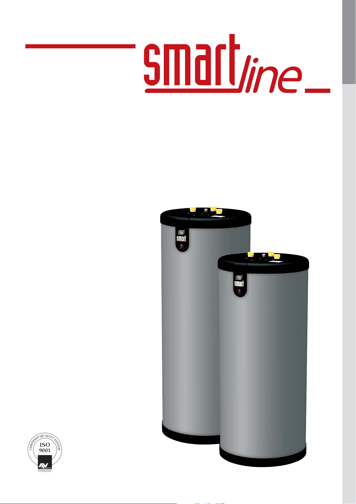
320 / 420 / 600 / 800
Installation, Operating and
Servicing Instructions
ENGLISHFRANCAISNEDERLANDSESPAÑOLITALIANODEUTSCH
661Y0700.B
EN • 1

INDEX
WARNINGS 3
Who should read these instructions 3
ENGLISHFRANCAISNEDERLANDSESPAÑOLITALIANODEUTSCH
Symbols 3
Recommendations 3
Applicable standards 3
Warnings 3
Packing 3
INTRODUCTION 4
Description of the specifications 4
Description of operation 4
TECHNICAL CHARACTERISTICS 5
Operating condition 5
Wiring diagram 5
INSTALLATION INSTRUCTIONS 6
Dimensions 6
Domestic hot water connections 6
Installation 6
Central heating connections 7
COMMISSIONING 8
Filling the tank 8
Check to be carried out before start-up 8
Setting the thermostat 8
MAINTENANCE 9
Periodic checks by the user 9
Annual service 9
Emptying 9
SPARE PARTS 10
661Y0700.B
EN • 2
WARNINGS
WHO SHOULD READ THESE INSTRUCTIONS
These instructions should be read by:
- the specifying engineer
- the installer
- the user
- the service engineer
SYMBOLS
The following symbols are used in this manual:
Essential instruction for
the correct operation of
the installation.
Essential instruction for
the safety of persons
and the environment.
Danger of electrocution.
• It is important to switch the tank OFF before carrying out
any work.
• There are no user accessible parts inside the tank casing.
APPLICABLE STANDARDS
The appliances carry the CE mark in accordance with the
standards in force in the various countries.
WARNINGS
This documentation is part of the information delivered with the
appliance and must be given to the user and stored in a safe
place!
An approved installer must carry out the assembly, commissioning,
maintenance and repair of the system, in accordance with current
standards in force.
ENGLISHFRANCAISNEDERLANDSESPAÑOLITALIANODEUTSCH
Danger of burns
RECOMMENDATIONS
• Please, read carefully this manual before installing and
commissioning the tank.
• It is prohibited to carry out any modifications to the inside of
the appliance without the manufacturer’s prior and written
agreement.
• The product must be installed and serviced by trained
engineers, in compliance with current standards.
• The installation must comply with the instructions in this
manual and with the codes and standards governing systems
for the production of hot water.
• Any failure to follow instructions relating to tests and test
procedures may result in personal injury or risks of pollution.
• To guarantee safe and correct operation of the appliance, it
is important to have it serviced and maintained every year by
an approved installer or maintenance company.
ACV shall not accept any responsibility for damage caused by noncompliant location of the system or by use of the parts or
connections not approved by ACV for this application.
The manufacturer reserves the right to change the
technical characteristics and specification of its
products without notice.
The availability of some versions and their accessories is
market dependant.
PACKING
Units are shipped ready to install, tested and packaged in a carboard box.
Contents of the package
• One hot water tank.
• One multilingual technical instruction manual.
• In case of anomaly, please call your service engineer.
• The parts may only be replaced by genuine factory parts. You
will find a list of the spare parts and their reference number
ACV to the end of this document.
661Y0700.B
EN • 3

INTRODUCTION
DESCRIPTION OF THE SPECIFICATIONS
“Tank-in-Tank” system
ENGLISHFRANCAISNEDERLANDSESPAÑOLITALIANODEUTSCH
“Tank-in-Tank” is a heat exchanger with a built-in accumulator, made
up of two concentric tanks: the inner tank contains domestic water
to be reheated (secondary) and the outer tank contains the heating
fluid (primary) which circulates between the two tanks and transfers
its heat to the domestic water.
Hot water exchanger accumulator
The inner tank is the heart of the tank: it is subject to the
aggressiveness of the supply water, to high pressures and to
variations in temperature. This tank is made of solid chromenickel stainless steel (stainless steel 304 or duplex), fully welded
under argon protection using the Tungsten Inert Gas (T.I.G.)
technique.
Before assembly, the convex bottoms are pickled and passivated in
order to improve the tank’s lifespan and in particular its resistance to
corrosion. The shell is corrugated all the way up using an exclusive
manufacturing process. This design gives considerable resistance to
pressure and limits the adherence of lime scale by allowing the tank
to expand and contract.
Outer tank
The outer tank containing water from the primary circuit arriving
from the boiler, is made of carbon steel STW 22.
Thermal Insulation
This is carried out using high densit y injected polyurethane
foam, 50 mm containing no CFCs.
Lining
The tank is covered using polypropylene, a plastic material which
offers a high resistance to shocks and which is also very pleasing
to the eye.
DESCRIPTION OF OPERATION
Operating cycle
The thermostat is triggered and starts up the pump which loads the
heating fluid. This fluid circulates around the inside tank and heats
up the domestic water. When the required temperature is reached,
the thermostat stops the loading pump.
OFF Reheating Running Tepping
Cold Water
Domestic hot water
Heating fluid
Losses when shut down in Watt
Models
SL 320 ΔT = 50 K 94,4
SL 420 ΔT = 50 K 102,8
SL 600 ΔT = 50 K 110,5
Losses in
[Watt]
1 8
2
3
4
5
6
SL 800 ΔT = 50 K 121,7
Temperature losses with ambient T° of 20°C
9
1. A uxil i a r y c on n e c t io n DH W
2. Domestic cold water inlet
3. Poly ur ethane foam insulation 50 mm
4. Flow connection [primary circuit]
5. Stainless steel (304 or Duplex) inner tank
6. Return connection [primary circuit]
7. Out er steel tank [primar y circuit]
10
8. Manual air val ve
9. Domestic ho t water outle t
10. Polypropylene top lid
11. Polypropylene shell
12. Polypropylene bottom lid
11
7
661Y0700.B
12
EN • 4

TECHNICAL CHARACTERISTICS
OPERATING CONDITION
Maximum service pressure [tank filled with water]
- Heating circuit: Smart 320 / 420 / 600 / 800 4 bar
Smart 320 / 420 Duplex 6 bar
Smart 600 / 800 Duplex 5 bar
- DHW circuit: 10 bar
Operating temperature
- Maximum temperature: 90°C
Water quality
• Chlorides: < 150 mg/L [304 Stainless steel]
< 2000 mg/L [Duplex]
• 6 ≤ ph ≤ 8
ENGLISHFRANCAISNEDERLANDSESPAÑOLITALIANODEUTSCH
SL
Tank characteristics
Total capacity L 318 413 606 755
Primary capacity L 55 55 161 184
Primary fl uid fl ow rate L/h 6200 6400 7200 7500
Primary pressure drop mbar 90 95 92 175
Heating surface m
2
Tank performances
Peak fl ow at 40°C L/10’ 922 1195 1345 1820
Peak fl ow at 45°C L/10’ 790 1012 1153 1474
Peak fl ow at 60°C L/10’ 504 620 706 948
Peak fl ow at 40°C L/60’ 2666 3151 3437 4039
Peak fl ow at 45°C L/60’ 2285 2608 2946 3263
Peak fl ow at 60°C L/60’ 1368 1513 1733 1811
Constant fl ow at 40°C L/h 2093 2536 2511 2888
Constant fl ow at 45°C L/h 1794 2058 2152 2347
Constant fl ow at 60°C L/h 1037 1153 1232 1306
Pre-heating time minutes 23 24 35 66
Puissance puisée kW 73 88 88 96
Running conditions: 85°C Water intake T°: 10°C
320
2,65 3,24 3,58 4,36
SL
320
SL
420
SL
420
SL
600
SL
600
SL
800
SL
800
WIRING DIAGRAM
1. Co n t r o l t h e r mos t a t [6 0/9 0 °C]
2. Lo ad pump [in option]
3. Manual reset high limit thermostat [103°C max.]
Bk
2
1
c
t
1
c
3
t
1
c
t
1
1
2
OrOr
Y/Gr
Bk
Y/Gr
L1 N
Br
W
Bk
T2 S3T1NL1
R
Or
Br
Y/Gr
B
NL1
Y/Gr
T2S3 T1 NL1
2
PH
NO
NC
SL 320 - 420
SL 320 - 420
SL 600 - 800
B. Blue
Bk. Black
Br. Brown
R. Red
Or. Orange
W. W h ite
Y/ Gr . Ye l l o w/ G r ee n
(UK version)
661Y0700.B
EN • 5

INSTALLATION INSTRUCTIONS
DIMENSIONS
ENGLISHFRANCAISNEDERLANDSESPAÑOLITALIANODEUTSCH
A mm 1593 2018 1892 2292
B mm 1280 1705 1583 1983
C mm 250 250 255 255
D mm 660 660 817 817
Weight empty [kg] 141 167 238 280
A
SL
320
B
C
SL
420
SL
600
135
DOMESTIC HOT WATER CONNECTIONS
The installation of a domestic safety unit is compulsory.
In order to avoid water dropping on the tank, the
domestic safety unit should not be placed directely
above the tank.
The third domestic water outlet can be used as a
return from the domestic hot water circulation loop.
SL
800
INSTALLATION
This hot water tank should not be installed where it will be exposed
to outside weather conditions.
Choose the most appropriate location according to the position of
the boiler and the proximity of the domestic hot water distribution
system, in order t o reduce hea t losses and minimise the pressure
drops.
Only for floor-standing installation.
135
D
HYDRAULIC CONNECTIONS
Models Heating connections
SL 320 / 420 Ø 1”1/2 [F]
135
SL 600 / 800 Ø 2" [F]
Models DHW connectons
SL 320 / 420 / 600 / 800 Ø 1”1/2 [M]
8
2
1
33
4
1
5
1
7
9
3
1 1
1
10
Mains water kits could be in some countries due to
approval regulations.
Recommendations
• The pipe feeding the tank with cold water must be fitted
with a safety unit comprising at least the following:
- An isolating valve [1]
- a non-return valve [3]
- a safety valve [4]:
- a sanitary expansion vessel of appropriate dimensions.
• When the operating pressure exceeds 6 bar a pressure
reducer [2] must be installed before the safety unit.
• Union fittings are recommended for easy removal of the
connections. Ideally the “dielectric” version is preferable
in order to protect the connections against corrosion in
the presence of dissimilar metals such as copper and
galvanised steel.
• The installation of an expansion vessel avoids safety valve
runoff (loss of water).
• Domestic hot water expansion vessel capacit y:
18 Litres: for the following models: 320
24 Litres: for the following models: 420
35 Litres: for the following models: 600 / 800
(set to < 10 bar)
6
1. Is o l a t i n g v a l v e
2. Pressure reducer
3. Non-r et urn valve
4. Expansion tank
5. Saf et y valve
6. Drain cock
7. A i r v e n t
8. Thermo st at ic mi xing v alve
9. Circulation pump
10. Drawoff point
Please see the technical instruction manual of the
expansion vessel’s manufacturer for further details.
661Y0700.B
EN • 6

INSTALLATION INSTRUCTIONS
CENTRAL HEATING CONNECTIONS
1. System filling valve
2. Safety valve calibrated to 3 bar
3. Expan sion v essel
4. Drain cock
5. Isolation valve, heating system
6. Room thermos tat
ENGLISHFRANCAISNEDERLANDSESPAÑOLITALIANODEUTSCH
7. Optional boiler control [BC 01 or BC 03]
8. Boiler pump
9. Heating pump
10. 3-ways motorized mixing valve
Tank wit h lo a d pu mp
5
8
5
9
1
2
3
Tank wit h th r ee w ays
motorized mixing valve.
6
6
7
10
5
8
5 5
1
2
3
5
4
4
7
5 5
425 850
235
2"
425 850 850
235
2"
1700
2550
2" 1
1/2
"
2" 1
Battery formation of 3 indirect water heaters
10800128 Kit battery 2x SL 320 - 420 - 600 - 800
1/2
"
10800129 Kit battery 3x SL 320 - 420 - 600 - 800
6
5
8
9
1
2
3
5
4
7
5 5
661Y0700.B
EN • 7

COMMISSIONING
ENGLISHFRANCAISNEDERLANDSESPAÑOLITALIANODEUTSCH
Before pressurising the central heating tank (primary)
you should first pressurise the domestic hot water
tank (secondary).
Both the domestic hot water tank and the central
heating tank must be filled before using the tank.
FILLING THE TANK
Domestic hot water tank
1. Close the drain cock [6] of the DHW circuit.
2. Open the isolating valve [1] of the DHW circuit for the filling.
3. Bleed the air in the circuit by turning on a nearby hot water
tap [10] Fill the tank until the flow rate stabilises.
4. Turn off the hot water tap [10].
8
2
1
33
4
1
5
6
1
7
9
3
1 1
1
CHECKS TO BE CARRIED OUT BEFORE START-UP
• Safety valves (domestic hot water) and (central heating)
correctly installed and discharge connected to the drains.
• Domestic hot water tank and primary circuit filled with
water.
• Air bleed correctly carried out on both circuits.
• Air valve sealed.
• Both hot and cold water pipes correctly connected to the
tank’s hot water circuit.
• Heating feed and return correctly connect ed to the tank.
• The electrical cabling is correct.
• The tank’s thermostat is set according to the instructions
shown in § “Setting the thermostat”.
• Connections checked and free of leaks.
SETTING THE THERMOSTAT
Factory settings
10
The thermostat of the tank is factory preset to the minimum
recommended by the standards, over a range of settings from
60 to 90°C.
To increase the temperature: turn the button clockwise.
To reduce the temperature: turn the button anticlockwise.
When adjusting the tank’s thermostat, make sure that the
boiler temperature is set to a value at last 10°C higher than
tank’s thermostat.
Central heating tank
1. Close the drain cock [4] on the tank’s primary circuit.
2. Open the isolation valves [5] on the central heating circuit
connected to the boiler.
3. Bleed the air in the circuit by opening the air vent located on
the upper part of the tank.
4. Follow the instructions supplied with the boiler for filling.
5. When the tank is full and the air has been removed, the
bleed valve should be closed.
6
5
8
9
1
2
5
3
Ensure that the bleed valve is properly sealed.
6. If any antifreeze is needed in the primary circuit it must be
compatible with Public hygiene rules and not be toxic.
A food-type Propylene Glycol is recommended.
Consult the manufacturer to ensure that the antifreeze is
compatible with the tank’s construction materials.
7
5 5
4
Recommendations
There is a risk that bacteria including “Legionella
pneumophila” may develop if a minimum temperature
of 60°C is not maintained both in storage and in the
hot water distribution network.
There is a risk of scalding from hot water!
ACV recommends the use of a thermostatic mixing
valve set to provide water at 60 °C or less.
• The water heated to wash clothes, dishes and for other
purposes can burn and cause serious injury.
• Children, the elderly, the sick or the disabled are the most at
risk from burns due to very hot water. Never leave them on
their own in a bath or under the shower. Never allow young
children to turn on hot water taps or fill their own baths.
• Set the water temperature appropriately according to the
intended use and plumbing codes.
When repeatedly drawing small amounts of hot water,
a “stratification” effect may develop in the tank.
The upper layer of hot water may then reach very high
temperatures. A thermostatic mixing valve will stop
water at excessivly high temperatures reaching the
outlets.
Never use car antifreeze or undiluted antifreeze.
This can cause serious injury, death or damage to the
premises.
661Y0700.B
EN • 8

MAINTENANCE
PERIODIC CHECKS BY THE USER
• Check the pressure of the boiler’s pressure gauge: it should
be between 0.5 and 1.5 bar.
• Carry out a monthly visual inspection of the valves,
connections and accessories in order to detect any leaks
or malfunctions.
• Periodically check the air valve located on the upper part of
the tank to make sure that it is not leaking.
• If you notice anything unusual, contact a technician or your
heating engineer.
ANNUAL SERVICE
The annual service, carried out by a technician, must include
the following:
• Checking the air valve:
The air bleed can lead t o water being added to the system.
Check the pressure on the boiler’s pressure gauge.
• Manually activate the domestic hot water safety valve once
a year. This operation will lead to a discharge of hot water.
Before drawing any hot water through the safety unit,
make sure that the discharge goes directly to the drain
in order to avoid any risk of burning or damage.
• The discharge pipe should be open to the atmosphere.
• If the safety unit occasionally “drips” this may be due to an
expansion problem or to clogging of the valve.
• Follow the circulator’s maintenance instructions.
• Check that the valves, cocks, controllers and any electrical
accessories installed are working properly (see the
manufacturer’s instructions if necessary)
.
Domestic hot water tank
To empty the domestic hot water tank:
1. Switch off the electrical power supply to the tank.
2. Close the isolation valve [1].
3. Open the drain cock [6] and the air vent [7].
4. Allow the water to flow out into the drain.
5. After emptying, return the valves to their initial positions.
In order to allow emptying, the drain valve [6] must be
located at the lowest point on the tank.
8
2
1
33
4
1
5
6
1
7
9
3
1 1
1
10
Central heating tank
To empty of f the primary circuit:
ENGLISHFRANCAISNEDERLANDSESPAÑOLITALIANODEUTSCH
EMPTYING
Recommendations
Empty the tank if it is to be switched off during
the winter and there is a risk of frost conditions
exposure.
If the central heating water (primary circuit) contains
any antifreeze, only the domestic hot water should
be drained.
Before draining off the domestic hot water, insulate
the tank to reduce the central heating pressure
(primary circuit) to 1 bar, in order to protect the
tank against a risk of collapsing.
If the central heating circuit does not contain any
antifreeze, both the central heating and hot water
circuits should be drained.
1. Switch off the electrical power supply to the tank.
2. Close the shut-off valves [5] on the primary circuit.
3. Connect a hose to the drain valve [4].
4. Open the drain valve [4] and drain the hot wat er off.
5. To speed up the process, open the air vent located on the
upper part of the tank.
6. When the emptying is finished, close the drain cock again
then screw the air valve up again.
6
5
8
9
1
2
3
5
7
5 5
4
661Y0700.B
EN • 9

ENGLISHFRANCAISNEDERLANDSESPAÑOLITALIANODEUTSCH
A01
N°
SL
320
SL
420
SL
600
SL
800
A02
A03
A04
SL 320 - 420
A01
A02
A03
A04
497B5001 497B5001 497B5007 497B5007
39438047 39438049 39438030 39438049
49410089 497B0029 49410044 497B0029
497B5000 497B5000 497B5006 497B5006
SL 320 - 420 (UK)
SL 600 - 800
55445006 55445006
54442045 54442045
54764021 54764021
24614154
54764020
661Y0700.B
24614152
EN • 10
 Loading...