

Page 1

INSTALLATION, OPERATION AND
MAINTENANCE INSTRUCTIONS
SMART Line
SL & SLEW
100 - 130 - 160 - 210 - 240
EN
FR
NL
ES
IT
DE
661Y1700 • C
PL
RU
Page 2

EN
TABLE OF CONTENTS
FR
NL
ES
IT
DE
PL
RU
GENERAL RECOMMENDATIONS ...............................................................4
USER'S GUIDE ..............................................................................................5
Control Panel (SLEW models only)
........................................................................................................... 5
APPLIANCE DESCRIPTION .........................................................................6
Models -
SL / SLEW 100 - 130 - 160 - 210 - 240 ................................................................................................. 6
TECHNICAL CHARACTERISTICS ...............................................................8
Dimensions and Main Characteristics
................................................................................................... 8
Electrical Characteristics ................................................................................................................................. 10
Performance .............................................................................................................................................................12
Maximum Operating Conditions .............................................................................................................12
INSTALLATION ......................................................................................... 13
Safety Instructions
...............................................................................................................................................13
Packing Contents ..................................................................................................................................................15
Tools.................................................................................................................................................................................15
Tank Installation : SL 100 / 130 / 160 / 210 / 240 .........................................................................16
Tank Installation : SLEW 100 / 130 / 160 / 210 / 240.................................................................17
Connection ................................................................................................................................................................18
SLEW tank used as electric DHW tank only ..................................................................................... 21
Available Kits and Accessories ...................................................................................................................21
STARTING UP ............................................................................................22
Safety Instructions to Fill the Tank
..........................................................................................................22
Filling ..............................................................................................................................................................................23
Checks before Starting up .............................................................................................................................25
en
2
Smart Li ne SL - SLE W : 661Y1700 • C
Page 3

TABLE OF CONTENTS
EN
MAINTENANCE ........................................................................................26
Periodic Checks by the User
........................................................................................................................26
Annual Maintenance .........................................................................................................................................26
Draining ........................................................................................................................................................................27
Bringing back into Service after Maintenance .............................................................................28
Replacement of the Electric Heating Element (SLEW tank) ..............................................29
Fault Finding .............................................................................................................................................................30
FR
NL
ES
IT
DE
Smart Li ne SL - SLE W : 661Y1700 • C
PL
RU
en
3
Page 4

EN
GENERAL RECOMMENDATIONS
NOTES
FR
NL
ES
IT
DE
PL
RU
• This manual contains important information with respect to the installation, the starting up
and the maintenance of the hot water tank.
• This manual must be provided to the user, who will read it carefully and keep it in a safe
place.
• The availability of certain models as well as their accessories may vary according to the markets.
• The manufacturer reserves the right to change the technical characteristics and features of
its products without prior notice.
We accept no liability should any damage result from the failure to comply with theinstructions contained in this technical manual.
Essential instructions forthe safety of persons and the environment
• It is strictly prohibited to bring any modification to the appliance, without
themanufacturer’s prior written approval.
• The appliance must be installed by a qualified installer, in accordance with
applicable regulations.
• The installation must comply with the instructions contained in this manual and
with the regulations applicable to installations.
• Failure to follow the instructions in this manual could result in personal injury or a
risk of environmental pollution.
• The manufacturer declines all liability for any damage caused as a result of
incorrect installation or in the event of the use of appliances or accessories that are
not approved by the manufacturer.
Essential instructions forthecorrect operation oftheinstallation
• In order to ensure that the appliance operates correctly, it is essential to have it
serviced by a certified installer or maintenance contractor every year.
• In case of problem, please contact your installer for advice.
• Faulty parts must only be replaced with genuine parts.
• Our domestic hot water tanks are designed and manufactured exclusively for the
heating and storage of domestic hotwater.
• The domestic hot water heaters must only be heated using hot water in a closed
circuit.
• The part number (N° Art.) and serial number (N° Ser.) of the tank are indicated on
its rating plate and must be provided to ACV in case of warranty claim. Failure to
do so will make the claim void.
en
4
Smart Li ne SL - SLE W : 661Y1700 • C
Page 5

USER'S GUIDE
CONTROL PANEL SLEW models only
1
3
2
4
Heating
element ON
Heating
element OFF
EN
FR
NL
ES
IT
DE
Key :
1. Control thermostat [60/90°C] - To set the domestic hot water (DHW) temperature.
2. Fuse FF 12,5 Amp - To provide an electric protection to the appliance.
3. Summer / Winter switch - To activate the heating pump of the installation/deactivate the elec-
trical heating element (
the installation pump (
4. Heating-element-on indicator - The built-in indicator lights when the heating element is acti position of the summer / winter switch).
vated (
- winter position) or activate the electrical heating element/deactivate
- summer position).
Smart Li ne SL - SLE W : 661Y1700 • C
PL
RU
en
5
Page 6

EN
APPLIANCE DESCRIPTION
FR
NL
ES
IT
DE
MODELS
SL : Storage water tanks, to be installed on the oor or either vertically or horizontally on the
SLEW : Storage water tanks, to be installed vertically on the wall, that can work within a heating
SL / SLEW 100 - 130 - 160 - 210 - 240
wall, that work within a heating installation.
installation, or independently as an electric domestic hot water heater. The SLEW tank
is equipped with one 2200 W heating element controlled by the thermostat and by the
Summer/Winter switch on the appliance control panel.
1
2
3
8
9
10
4
14
PL
RU
5
15
11
6
12
7
13
8
SL 100 - 130 - 160 - 210 - 240
en
6
Smart Li ne SL - SLE W : 661Y1700 • C
Page 7

APPLIANCE DESCRIPTION
EN
1. Auxiliary connection DHW
2. Cold water inlet connection
3. Control thermostat
4. Flow connection (primary circuit)
5. Polyurethane foam insulation
6. Return connection (primary circuit)
7. Outer steel tank (primary circuit)
8. Manual air bleed valve (x 2 - SL Mo dels)
9. Hot water outlet connection
8
4
5
9
15
14
10. Polypropylene top lid
11. Stainless steel tank (DHW)
12. Polypropylene shell
13. Polypropylene bottom lid
14. DHW thermometer
15. Dry well
16. Control panel
17. Electric heating element 2200 W
10
7
11
12
6
FR
NL
ES
IT
DE
PL
17
16
RU
1
13
3
2
SLEW 100 - 130 - 160 - 210 - 240
en
Smart Li ne SL - SLE W : 661Y1700 • C
7
Page 8

EN
TECHNICAL CHARACTERISTICS
DIMENSIONS AND MAIN CHARACTERISTICS
FR
NL
ES
IT
DE
PL
RU
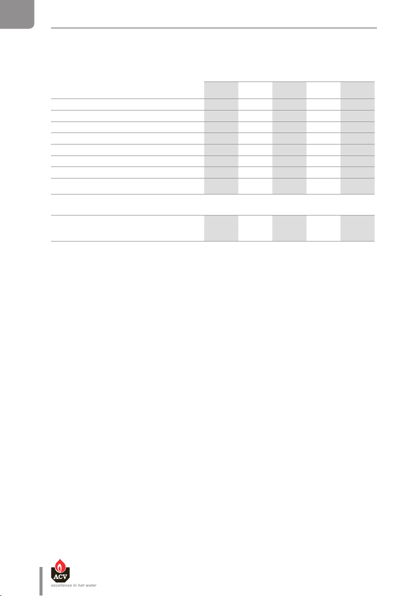
Tank dimensions
100 130 160 210 240
A mm 865 1,025 1,225 1,497 1,744
B mm 629 789 989 1,261 1,508
C mm 365 525 725 997 1,244
Empty weight Kg 49 55 65 75 87
Main characteristics
100 130 160 210 240
Total capacity L 105 130 161 203 242
Primary circuit capacity L 30 31 35 39 42
Primary circuit connection [F] " 1 1 1 1 1/4 1 1/4
DHW connection [M] " 3/4 3/4 3/4 3/4 3/4
Auxiliary DHW loop connection [F] " 3/4 3/4 3/4 3/4 3/4
Primary uid ow rate L/h 2100 2600 3500 4200 5500
Primary pressure drop mbar 17 22 37 45 51
Heating surface area m² 1.03 1.26 1.54 1.94 2.29
Main characteristics
100 130 160 210 240
Total capacity L 105 130 161 203 242
Primary circuit capacity L 30 31 35 39 42
Primary circuit connection [F] " 1 1/4 1 1/4 1 1/4 1 1/4 1 1/4
DHW connection [M] " 3/4 3/4 3/4 3/4 3/4
Auxiliary DHW loop connection [F] " 3/4 3/4 3/4 3/4 3/4
Primary uid ow rate L/h 2100 2600 3500 4200 5500
Primary pressure drop mbar 17 22 37 45 51
Heating surface area m² 1.03 1.26 1.54 1.94 2.29
SL / SLEW
SL
SLEW
en
8
Smart Li ne SL - SLE W : 661Y1700 • C
Page 9

TECHNICAL CHARACTERISTICS
A
C
360
325
295
145
565
325
A
360
325
295
145
SL
264
EN
FR
B
NL
ES
SLEW
B
264
5
295
IT
360
565
DE
PL
C
RU
325
5
295
Smart Li ne SL - SLE W : 661Y1700 • C
360
565
en
9
Page 10

EN
SL
FR
NL
TECHNICAL CHARACTERISTICS
ELECTRICAL CHARACTERISTICS
Main characteristics
Rated voltage V~ 230 230 230 230 230
Rated frequency Hz 50 50 50 50 50
Max. Amp rating A 6 6 6 6 6
100 130 160 210 240
SL
ES
IT
DE
PL
RU
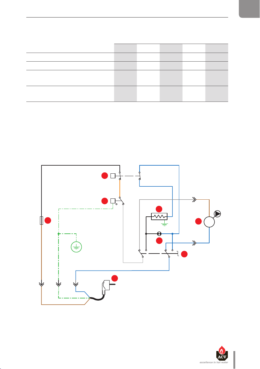
Wiring diagram
1. 230 Volt supply cord
2. Control thermostat [60/90°C]
3. Manual reset high limit thermostat [96°C max.]
4. Summer / Winter switch
5. Fuse FF 12,5 A
6. Electric heating element
7. Charging pump [option]
8. Heating-element-on indicator
SL
Bk
2
1
c
t
2
Y/Gr
L1 N
OrOr
Bk
Br
Y/Gr
B
N L1
7
10
B. Blue
Bk. Black
Br. Brown
G. Grey
Or. Orange
W. White
Y/Gr. Yellow/Green
en
Smart Li ne SL - SLE W : 661Y1700 • C
Page 11
TECHNICAL CHARACTERISTICS
B
EN
Main characteristics
100 130 160 210 240
SLEW
Rated voltage V~ 230 230 230 230 230
Rated frequency Hz 50 50 50 50 50
Electrical consumption with
electrical heating element
Rated current with electrical
heating element
W 2,200 2,200 2,200 2,200 2,200
A 10 10 10 10 10
SLEW
3
t
Or
c
2
t
Y/Gr
5
2 1
B
Gr Br
6
Bk
Bk B
8
T1
7
M
T2
BB
FR
NL
ES
IT
DE
PL
Br Bk
Y/Gr
L1 PE N
W
B
1
B
4
RU
230 V ~50Hz
B
Y/Gr
Br
en
Smart Li ne SL - SLE W : 661Y1700 • C
11
Page 12
EN
TECHNICAL CHARACTERISTICS
PERFORMANCE
FR
NL
ES
IT
DE
PL
DHW performance*
100 130 160 210 240
Peak ow at 40 °C L/10' 236 321 406 547 700
Peak ow at 60 °C L/10' 117 161 209 272 337
Peak ow at 40 °C L/60' 784 1,063 1,349 1,820 2,319
Peak ow at 60 °C L/60' 384 549 689 913 1,165
Constant ow at 40 °C L/h 658 890 1,132 1,527 1,943
Constant ow at 60 °C L/h 320 465 576 769 994
Power drawn kW
Initial heating time Minutes
Heating time with the 2.2 kW
heating element from 10 to 60°C
Conditions: Primary circuit temp.: 85°C, water supply temp.: 10°C
23 31 39 53 68
24 22 22 20 20
2 h 43' 3 h 27' 4 h 20' 5 h 37' 6 h 37'
SL / SLEW
SL EW O NLY
MAXIMUM OPERATING CONDITIONS
Maximum Service Pressure [tank full of water]
- Primary circuit : ..................................................3 bar
- DHW water circuit : ...................................... 8.6 bar
RU
Maximum Temperature
- Maximum DHW temperature : ....................90°C
Supply Pressure (DHW circuit)
- Max. 6 bar without requiring a pressure reducing valve
Water Q uality
- Chlorides < 150 mg/L (304 Stainless steel)
< 2000 mg/L (Duplex)
- 6 ≤ pH ≤ 8
- If the water hardness is > 20°fH, the installation of a water softener is recommended.
en
12
Smart Li ne SL - SLE W : 661Y1700 • C
Page 13

INSTALLATION
SAFETY INSTRUCTIONS
EN
General remark
• Connections (electrical, hydraulic) must be carried out in accordance with
applicable standards and regulations.
• If the water drawing off point is far from the tank, installing an auxiliary DHW loop
can allow to get hot water more quickly at all times.
Essential instructions forthecorrect operation oftheinstallation
• The tank must be installed in a dry and protected area.
• Install the appliance to ensure easy access at all times.
• To avoid any risk of corrosion, connect the stainless steel tank directly to the earth.
• Make sure to inst all a pressure reducing valve set at 4.5 bar in the DHW circuit if the
supply pressure is higher than 6 bar.
• On the DHW circuit, install an approved safety group, comprised of a safety valve
set at 7 bar, a check valve and a stop valve.
• Make sure that the outlet of the safety unit goes directly to the sewer to avoid any
potential damage.
• Do not install the safety group above the tank to avoid water discharge on to the
tank.
FR
NL
ES
IT
DE
PL
Smart Li ne SL - SLE W : 661Y1700 • C
en
en
13
13
RU
Page 14
The risk of developing bacteria exists, including “Legionella pneumophila”,
EN
INSTALLATION
Essential instructions forthe safety of persons and the environment
FR
NL
ES
IT
DE
PL
• Hot water can burn!
In the event of small amounts of hot water repeatedly being drawn off, a
stratification effect can develop in the tank. The upper hot water layer may then
reach very high temperatures.
• ACV recommends using a pre-set thermostatic mixing valve in order to provide
hot water at a maximum of 60°C.
• Water heated to wash clothes, dishes and for other uses can cause serious burns.
• In order to avoid exposure to extremely hot water that can cause serious burns,
never leave children, old people, disabled or handicapped people in the bath
orshower alone.
• Never allow young children to turn on the hot water or fill their own bath.
• Adjust the wate r temperature in accordanc e with usage and plumbin g regulations.
•
ifaminimum temperature of 60°C is not maintained in both the DHW tank andthe
hot water distribution network.
Essential instructions for the electrical safety
• Only an approved installer is authorized to carry out the electrical connections.
• Install a 2-way switch and a fuse or circuit breaker of the recommended rating
outside the appliance, so as to be able to shut power down when servicing the
appliance or before performing any operation on it.
• Shut down external electrical supply of the appliance before performing any
operation on the electrical circuit.
RU
14
• This appliance is not intended for use by persons (including children) with reduced
physical, sensory or mental capabilities, or lack of experience and knowledge,
unless supervised or unless they have been given instruction concerning the use
of the appliance by a person responsible for their safety.
en
Smart Li ne SL - SLE W : 661Y1700 • C
Page 15

INSTALLATION
PACKING CONTENTS
All appliances are delivered, tested and packaged separately.
Package
• One SL/SLEW hot water tank.
• One multilingual Installation, Operation and Maintenance Instructions.
• One wall-mounting kit with support and ow diverter
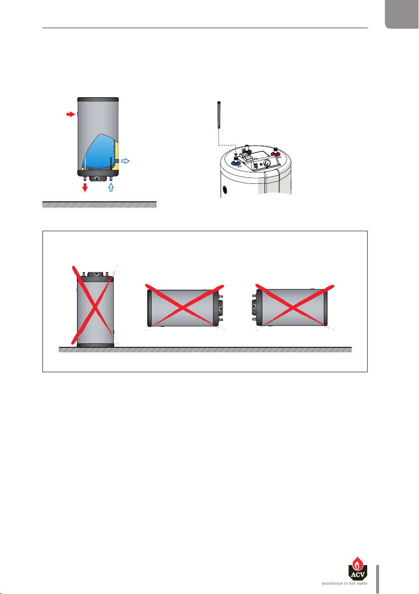
General Remark
• The hot water tank may be installed either on the floor or on a wall using the
provided wall-mounting kit (depending on the model).
Essential instructions for the correct operation of the installation
• When hung on a wall, the SLEW models must be assembled with the heating
element to the bottom (DHW pipes to the bottom).
• In horizontal configuration, the peak output and the first hour continuous output
will be reduced. In this case, we recommend to oversize the tank.
EN
FR
NL
ES
IT
TOOLS
Smart Li ne SL - SLE W : 661Y1700 • C
DE
PL
RU
en
15
Page 16
EN
INSTALLATION
TANK INSTALLATION : SL 100 / 130 / 160 / 210 / 240
FR
NL
ES
IT
DE
PL
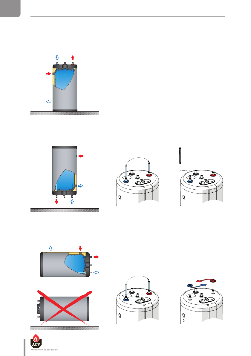
Floor mounting
Vertical wall hung position : domestic water connections at the bottom side
1
2
RU
Horizontal wall hung position : domestic water connections on the right side
1
en
16
Smart Li ne SL - SLE W : 661Y1700 • C
2
Page 17
INSTALLATION
TANK INSTALLATION : SLEW 100 / 130 / 160 / 210 / 240
EN
Vertical wall hung position : domestic water connections at the bottom side
SLEW
SLEW
FR
NL
ES
IT
DE
PL
Smart Li ne SL - SLE W : 661Y1700 • C
RU
en
17
Page 18

EN
INSTALLATION
CONNECTION
FR
NL
ES
IT
DE
PL
RU
Essential instructions forthe safety of persons and the environment
• Refer to the safety instructions for the installation. Failure to comply with these
instructions can result in damages to the installation, severe injuries or death.
• Hot water can burn! ACV recommends using a pre- set thermostatic mixing valve
in order to provide hot water at a maximum of 60°C.
Essential instructions forthecorrect operation oftheinstallation
• The filling circuit of the DHW tank must be equipped with a safety group,
comprised at least of a stop valve, a check valve, a safety valve set at 7 bar, and
possibly, an expansion vessel of the appropriate size. Make sure that the circuit
between the tank and the safety valve is always open.
• The third DHW tank connection, if any, can be used for the auxiliary DHW loop.
If the connection is not used, replace the protective plug by a brass plug of the
appropriate size.
General remarks
• In certain countries the domestic kits must be approved.
• The circuit illustrations are basic principle diagrams only.
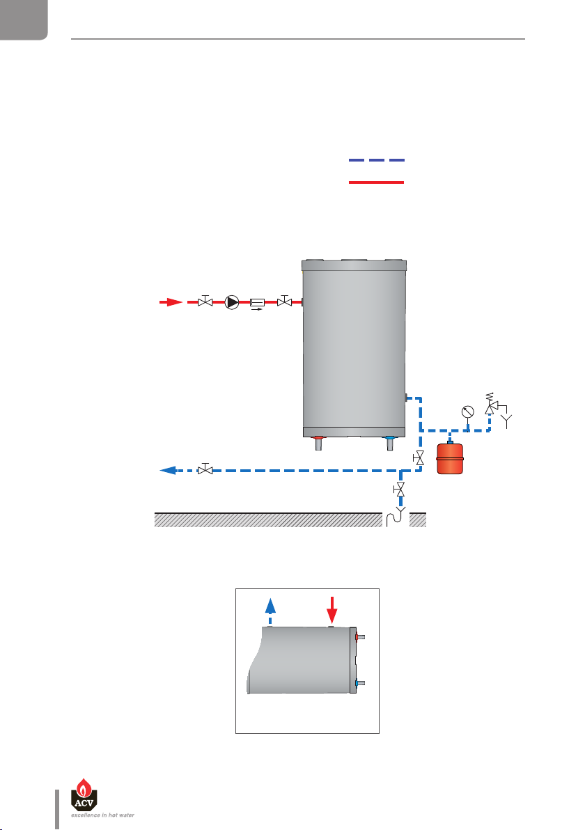
CONNECTION TO THE DHW CIRCUIT (Typical wall installation)
Key
1. Filling valve
2. Pressure reducing valve (set at 4.5 bar)
3. Check valve
4. Stop valve
5. DHW expansion vessel
6. Pressure gauge
7. Safety valve (set at 7 bar)
8. Drain valve
9. Grounding
10. Stop valve
11. Thermostatic mixing valve
12. Hot water outlet
12
11
Cold water
Hot water
5
10
9
1 2 3
4
7
6
8
18
Horizontal installation Vertical installation
en
Smart Li ne SL - SLE W : 661Y1700 • C
Page 19

INSTALLATION
CONNECTION TO THE DHW CIRCUIT (Typical floor installation)
2 3
1
Key
1. Filling valve
2. Pressure reducing valve (set at 4.5 bar)
3. Check valve
4. Expansion vessel
5. Safety valve (set at 7 bar)
6. Drain valve
7. Hot water outlet
8. Pressure gauge
9. Grounding
10. Stop valve
11. Thermostatic mixing valve
Cold water
Hot water
5
4
8
9
6
10
11
10
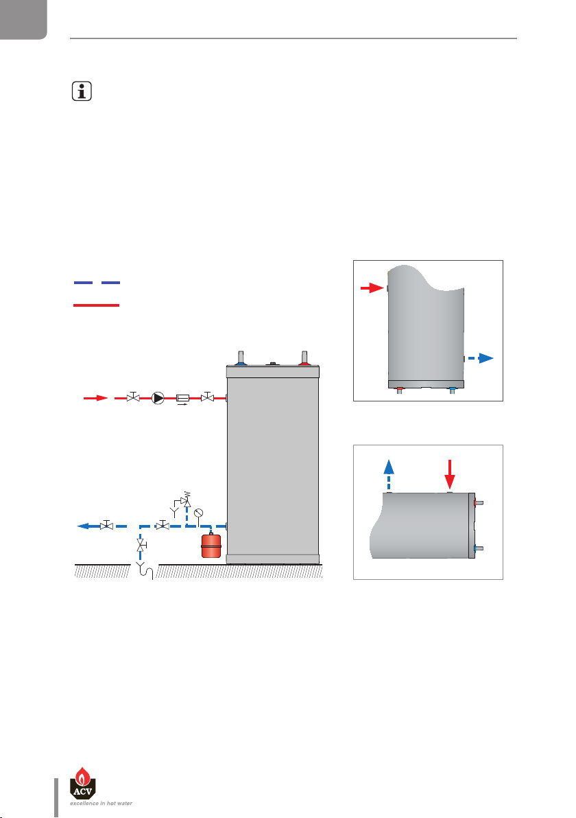
CONNECTION TO THE PRIMARY CIRCUIT Typical floor installation
EN
7
FR
NL
ES
IT
DE
Key
1. Primary circuit filling valve
2. Charging pump
3. Check valve
4. Primary circuit stop valve
5. Expansion vessel
6. Pressure gauge
7. Safety valve (set at 3 bar)
8. Drain valve
9. Stop valve
1 2 3
9
4
8
Smart Li ne SL - SLE W : 661Y1700 • C
PL
4
RU
6
5
en
19
Page 20
EN
INSTALLATION
CONNECTION TO THE PRIMARY CIRCUIT Typical wall installation
FR
NL
ES
IT
DE
PL
Key
1. Primary circuit filling valve
2. Charging pump
3. Check valve
4. Primary circuit stop valve
5. Expansion vessel
6. Pressure gauge
7. Safety valve (set at 3 bar)
8. Drain valve
9. Stop valve
9
Cold water
Hot water
2 3 41
7
6
4
5
8
RU
20
Vertical installation
Horizontal installation
en
Smart Li ne SL - SLE W : 661Y1700 • C
Page 21
INSTALLATION
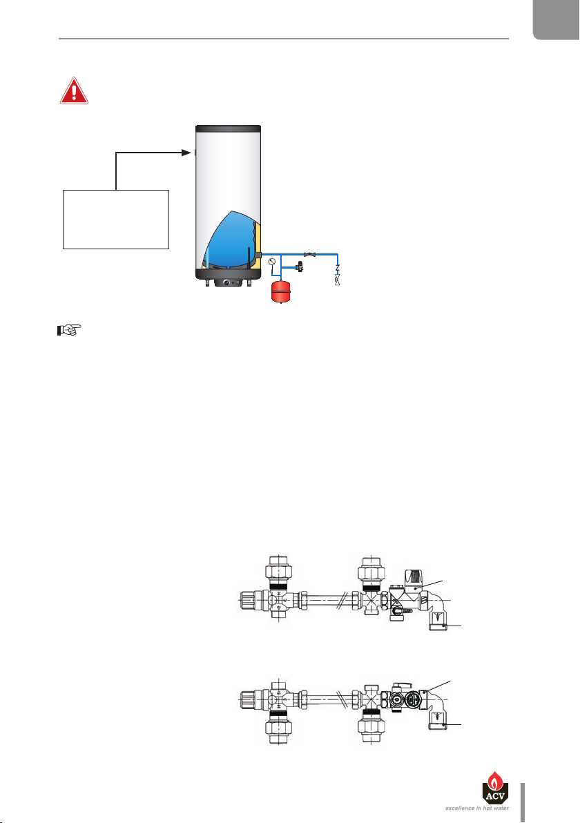
SLEW TANK USED AS ELECTRIC DHW TANK ONLY
EN
Do not power the heating element if the oustide tank is not filled and bled.
1. System lling valve
2. Safety valve calibrated to 3 bar
3. Expansion vessel
4. Isolation valve, heating system
5. Pressure gauge
This connection
to be plugged.
4
5
Essential instruction forthecorrect operation oftheinstallation
• Connections must be carrie d out in accordance with applicable standards and regulations.
2
1
3
AVAILABLE KITS AND ACCESSORIES
Domestic hot water kit
A. Thermostatic mixing valve
B. Mixed water outlet
C. Cold water inlet
D. Drainage connection
E. Expansion vessel connection
S. Safety unit
TH. Outlet hot water tank
TC. Inlet cold water tank
VERTICAL WALL MOUNTING
TCTH
FR
NL
ES
IT
DE
PL
A
B
E
VERTICAL FLOOR MOUNTING
B
A
Smart Li ne SL - SLE W : 661Y1700 • C
E
TCTH
S
C
C
D
S
D
RU
en
21
Page 22

EN
FR
NL
ES
IT
DE
STARTIN G UPS TART ING UP
SAFETY INSTRUCTIONS TO FILL THE TANK
SAFETY INSTRUCTIONS TO FILL THE TANK
Essential instructions forthe safety of persons and the environment
Essential instructions forthe safety of persons and the environment
• The DHW tank must always be filled and pressurise d before filling and p ressurising
• The DHW tank must always be filled and pressurise d before filling and p ressurising
the primary circuit.
the primary circuit.
• Do not use vehicle antifreeze. This can cause serious injury or death, or damage
• Do not use vehicle antifreeze. This can cause serious injury or death, or damage
facilities.
facilities.
• If antifreeze is needed in the primary circuit, it must comply with Public
• If antifreeze is needed in the primary circuit, it must comply with Public
Hygiene Regulations and must be non-toxic. A food-grade Propylene Glycol is
Hygiene Regulations and must be non-toxic. A food-grade Propylene Glycol is
recommended. It must be diluted according to the ratio recommended in the local
recommended. It must be diluted according to the ratio recommended in the local
regulations.
regulations.
• Consult the manu facturer to determi ne the compatibility o f the antifreeze with the
• Consult the manu facturer to determi ne the compatibility o f the antifreeze with the
tank's construction materials.
tank's construction materials.
Essential instructions forthecorrect operation oftheinstallation
Essential instructions forthecorrect operation oftheinstallation
• Before bringing the tank into service, check the connections to avoid any risk
• Before bringing the tank into service, check the connections to avoid any risk
ofleaks during filling.
ofleaks during filling.
• Only use drinking water to check that the DHW tank is watertight. The on-site
• Only use drinking water to check that the DHW tank is watertight. The on-site
testpressure must not exceed a pressure surge of 8,6 bar.
testpressure must not exceed a pressure surge of 8,6 bar.
• Using antifreeze in the primary circuit will lead to a reduction in the heating
• Using antifreeze in the primary circuit will lead to a reduction in the heating
performance. The higher the concentration of antifreeze in the circuit, the lower
performance. The higher the concentration of antifreeze in the circuit, the lower
the performance.
the performance.
PL
RU
22
en
Smart Li ne SL - SLE W : 661Y1700 • C
Page 23

1
Vertical installation
on a wall
Horizontal installation
on a wall
Figure 1
1
3
3
2
STARTIN G UP
FILLING
Essential instructions forthecorrect operation oftheinstallation
• The DHW ta nk must always be fill ed and pressurise d before filli ng and pressurising
the primary circuit.
EN
FR
FILLING THE DHW TANK Figure 1
General remark
• Connect the safety valve outlet to the sewer.
1. To fill the tank, open a hot water tap (2) located at the highest point of the installation. It
enables to bleed the air from the installation.
2. Open the filling valve (1) and the stop valves (3) to fill the DHW tank.
3. Close the hot water tap (2), after the water flow has stabilised and the air has been
completely evacuated.
4. Check all the connections of the installation for leaks.
2
3
3
Vertical installation
on a wall
NL
ES
IT
DE
PL
RU
Figure 1
Smart Li ne SL - SLE W : 661Y1700 • C
Horizontal installation
on a wall
Cold water
Hot water
en
23
Page 24
Cold water
Hot water
Vertical installation
on a wall
Horizontal installation
on a wall
Vertical installation
on a wall
Horizontal installation
on a wall
2
4
2
3
1
1
Figure 1
Figure 2
1
3
3
2
FILLING THE DHW TANK Figure 1
General remark
• Connect the safety valve outlet to the sewer.
1. To fill the tank, open a hot water tap (2) located at the highest point of the installation. It
enables to bleed the air from the installation.
2. Open the filling valve (1) and the stop valves (3) to fill the DHW tank.
3. Close the hot water tap (2), after the water flow has stabilised and the air has been
completely evacuated.
4. Check all the connections of the installation for leaks.
FILLING
Essential instructions forthecorrect operation oftheinstallation
• The DHW ta nk must always be fill ed and pressurise d before filli ng and pressurising
the primary circuit.
EN
STARTIN G UP
FILLING THE PRIMARY CIRCUIT Figure 2
FR
NL
ES
General remark
• If the tank is used within a heating installation, refer to the heating boiler manual.
1. Check that the drain valve (3) of your primary circuit is tightly closed.
2. Open the stop valves (1) and (2) of the primary circuit connected to the heating boiler.
3. Open the air bleed valve (4) located on the top of the hot water tank.
4. When the air is eliminated, cl ose the airbleed valve (4). Make sure the air bleed v alve is tight.
IT
DE
PL
RU
24
en
Smart Li ne SL - SLE W : 661Y1700 • C
Page 25

STARTIN G UP
CHECKS BEFORE STARTING UP
EN
• Check that the safety valves (DHW and primary) are correctly installed and that the outlets are
connected to the sewer.
• Check that the DHW tank and the primary circuit are filled with water.
• Check that the air has been correctly bled from both circuits.
• Check that the tank’s upper air bleed valve is tight.
• Check that the water side and heat source side pipes are correctly connected and not leaking.
STARTING UP PROCEDURE
If the SLEW tank is used as an electric DHW tank only :
1. Put the electric plug into the mains socket
2. Set the Summer / Winter switch on the summer (R) position and check that the indicator
is on.
3. Adjust the required temperature using the control thermostat.
FR
NL
ES
IT
DE
If the SMART tank is used within a heating installation:
To put the installation into service, refer to the heating boiler manual.
1. Put the Summer / Winter switch on the winter (T) position and check that the indicator is o.
2. Adjust the required temperature using the control thermostat.
Smart Li ne SL - SLE W : 661Y1700 • C
PL
RU
en
25
Page 26

EN
MAINTENANCEMAINTENANCE
PERIODIC CHECKS BY THE USER
FR
NL
ES
IT
DE
PL
• Check the pressure of the primary circuit pressure gauge: it should be between 0.5 and 1.5 bar.
• Visually inspect, on a regular basis, the valves, connections and accessories in order to detect
any leaks or malfunction.
• Periodically check the air bleed valve located on the tank top to ensure that itisnot leaking.
• Check that the DHW water circuit safety valves are in good operating condition.
• In the event of a problem, please contact an engineer or your installer.
ANNUAL MAINTENANCE
Essential instructions forthecorrect operation oftheappliance
• The discharge pipe of the safety unit must be open to the outside. If the safety
unit drips periodically, it may be due to an expansion problem or clogging ofthe
valve.
• For internal inspections , the hand hole can be used. If there is none, use one of the
water connections to insert the appropriate inspection equipment. If necessary,
drain the tank before inspection.
The annual maintenance service, performed by an engineer, must include:
• A check of the air bleed valve: the bleeding of air can lead to the need for adding water to
the system.
• A check of the primary and DHW circuit pressure gauges.
• The manual activation of the storage water circuit safety valve once a year. This operation
will lead to a discharge of hot water.
• A check of the correct operation of valves, taps, control units and accessories that are
possibly installed [refer to the manufacturer's instructions if necessary].
RU
26
en
Smart Li ne SL - SLE W : 661Y1700 • C
Page 27
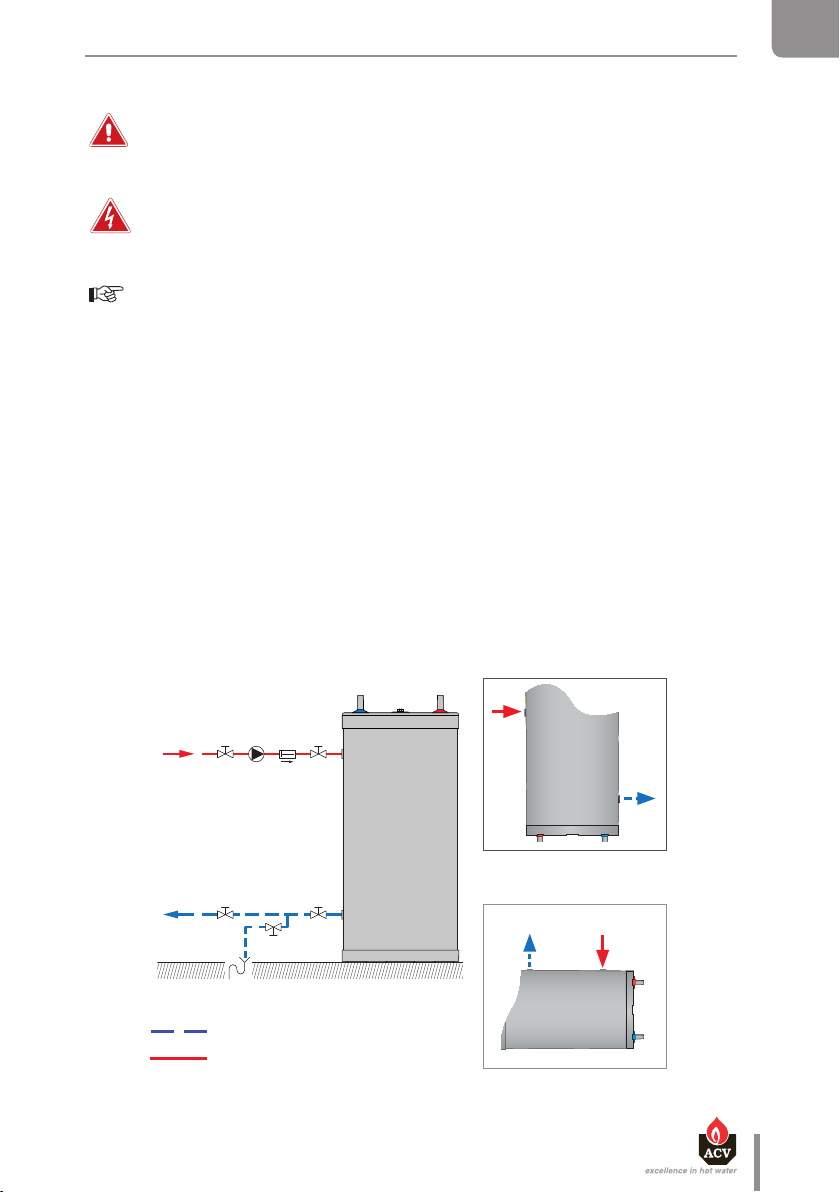
Figure 3
Cold water
Hot water
1
Vertical installation
on a wall
Horizontal installation
on a wall
1
1
2
3
MAINTENANCE
DRAINING
EN
Essential instructions forthe safety of persons and the environment
• The water coming out of the drain valve is very hot and can cause very severe
burns. Make sure the area around the hot water flow is clear of people.
Essential instructions for the electrical safety
• Shut down the external electrical supply of the installation before draining.
Essential instructions forthecorrect operation oftheinstallation
• Drain the tank if it is not used in winter and is at risk from exposure to ice. If the
primary circuit water contains antifreeze, only the DHW tank must be drained. If
the heating circuit does not contain antifreeze, the heating circuit and domestic
water must be drained.
• Before draining the DHW, isolate the tank and lower the pressure of the heating
circuit to 1 bar, in order to prevent the DHW tank from being crushed.
DRAINING THE PRIMARY CIRCUIT Figure 3
To drain the primary circuit of the hot water heater:
1. Stop the charging pump.
2. Isolate the hot water primary circuit byclosing the stop valves (1).
3. Connect the drain valve (2) to the sewer using a flexible hose.
4. Open the drain valve (2) and drain thewater from the primary circuit tothedrain.
5. Open the tank’s air bleed valve (3) toaccelerate drainage.
6. Close the drain valve (2) and air bleed valve (3) after draining the tank.
FR
NL
ES
IT
DE
PL
RU
en
Smart Li ne SL - SLE W : 661Y1700 • C
27
Page 28
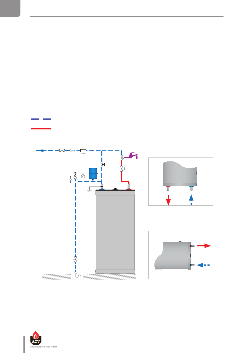
Figure 3
Figure 4
Cold water
Hot water
4
1
2
3
Vertical installation
on a wall
Horizontal installation
on a wall
Vertical installation
on a wall
Horizontal installation
on a wall
1
1
2
3
DRAINING
Essential instructions forthe safety of persons and the environment
• The water coming out of the drain valve is very hot and can cause very severe
burns. Make sure the area around the hot water flow is clear of people.
Essential instructions for the electrical safety
• Shut down the external electrical supply of the installation before draining.
Essential instructions forthecorrect operation oftheinstallation
• Drain the tank if it is not used in winter and is at risk from exposure to ice. If the
primary circuit water contains antifreeze, only the DHW tank must be drained. If
the heating circuit does not contain antifreeze, the heating circuit and domestic
water must be drained.
• Before draining the DHW, isolate the tank and lower the pressure of the heating
circuit to 1 bar, in order to prevent the DHW tank from being crushed.
DRAINING THE PRIMARY CIRCUIT Figure 3
To drain the primary circuit of the hot water heater:
1. Stop the charging pump.
2. Isolate the hot water primary circuit byclosing the stop valves (1).
3. Connect the drain valve (2) to the sewer using a flexible hose.
4. Open the drain valve (2) and drain thewater from the primary circuit tothedrain.
5. Open the tank’s air bleed valve (3) toaccelerate drainage.
6. Close the drain valve (2) and air bleed valve (3) after draining the tank.
EN
MAINTENANCE
DRAINING THE DHW TANK Figure 4
FR
NL
ES
IT
DE
PL
RU
To drain the hot water heater’s DHW tank:
1. Open fully the hot water tap (3) for at least 60 minutes to make sure the DHW tank has
cooled down sufficiently.
2. Close the filling valve (1) and the stop valve (4).
3. Connect the drain valve (2) to the sewer using a flexible hose.
4. Open the drain valve (2) and drain the water from the DHW tank to the sewer.
5. To accelerate the tank’s drainage, open a hot water tap located higher than the tank
connection in the DHW circuit.
6. Close the drain valve (2) and the hot water tap (3) after having drained the DHW tank.
BRINGING BACK INTO SERVICE AFTER MAINTENANCE
Refer to chapter "Starting Up", page 22
28
en
Smart Li ne SL - SLE W : 661Y1700 • C
Page 29

MAINTENANCE
REPLACEMENT OF THE ELECTRIC HEATING ELEMENT SLEW TANK
EN
• Switch o and disconnect the mains power supply to the appliance.
• Be careful with the high temperature of the cylinder.
• Drain the primary tank.
FR
NL
ES
IT
DE
4
PL
Max = 5,5 Nm
Min = 4,8 Nm
Smart Li ne SL - SLE W : 661Y1700 • C
3
RU
2
1
en
29
Page 30

EN
FR
NL
ES
IT
DE
MAINTENANCE
FAULT FINDING
What to do if the DHW-water is not heated anymore?
1
Check the power supply.
Check the proper operation of the boiler and the
2
control thermostat of the tank.
Check if the charging pump works properly and
3
replace if necessary.
4
Check the fuse and replace if necessary.
Check the safety thermostat on the tank and reset if
5
necess ary.
6
Check the heating element and replace if necessary.
1. Control thermostat [60/90°C]
2. Heating-element-on indicator
3. Summer/Winter switch
4. Fuse FF 12,5 Amp
5. Manual reset high limit thermostat [96°C max.]
6. Electric heating element
SL SLEW
PL
RU
30
2
1
en
3
5
4
Smart Li ne SL - SLE W : 661Y1700 • C
6
Page 31

RATING PLATE
SPECIMEN
KERKPLEIN N° 39
1601 RUISBROEK
BELGIUM
- - - - - - - - - - - - - - - - - - - - - - - - - - - - - - - - - - - - - -
06602601
N° Art. :
N° Ser. :
2014
Year :
99999
Type :
T. max.
:
:
Max. :
Max. :
(21) 99999 (91) 06602601 (92) 2014
www.acv.com
SMART 160L
90°C
230 V 50Hz
3 bar
10 bar
EN
FR
NL
ES
IT
DE
Smart Li ne SL - SLE W : 661Y1700 • C
PL
RU
en
31
Page 32
EN
FR
NL
ES
IT
DE
PL
RU
32
en
Smart Li ne SL - SLE W : 661Y1700 • C
 Loading...