

Page 1
P R E S T I G E
TECHNICAL
excellence in hot waterexcellence in hot water
Page 2

A place for the cd containing all the diagrams
presented in this book. Diagrams are in
AutoCad format.
Page 3

TABLE OF
CONTENTS
Description
INTRODUCTION
Page
04
HEAT EXCHANGER
CONSTRUCTION
WORKING PRINCIPLE
Technical characteristics
TECHNICAL DATA
DIMENSIONS
Connections
HEATING CONNECTIONS
PRESSURE DROP DIAGRAM - HEATING
HOT WATER CONNECTIONS
PRESSURE DROP DIAGRAM - HOT WATER
ELECTRICAL CONNECTIONS
CHIMNEY CONNECTIONS
Burner, regulator, cascade
BURNER
05
06
07
TABLE OF CONTENTS
08
09
10
10
11
11
12
15
16
REGULATOR ACV / MCBA
CASCADE OF BOILERS
Samples of installation
LEGEND
SCHEME 1
SCHEME 2
SCHEME 3
SCHEME 4
SCHEME 5
SCHEME 6
SCHEME 7
SCHEME 8
Prestige 50 - 75 Solo for 1 heating circuit and hot water production, weather dependent
regulation by the boiler MCBA and the room thermostat
Prestige Solo for 1 heating circuit and hot water production, weather dependent
regulation by the boiler MCBA and the Room Unit
Prestige Solo for 2 heating circuits and hot water production, regulated by the
boiler MCBA and the AM 3-11 module
Prestige Solo for 2 heating circuits and hot water production, regulated by the
boiler MCBA and the ZMC-1 module
Prestige Solo for 2 heating circuits and hot water production, regulated by the
Control Unit
Prestige Solo with solar system and SLME cylinder for 2 heating circuits
and hot water production, regulated by the Control Unit
Prestige Solo with solid fuel boiler for 2 heating circuits and hot water
production, regulated by the Control Unit
Cascade of 2 Prestige
regulated by the Control Unit
50 - 75
50 - 75
50 - 75
50 - 75
50 - 75 - 120
50 - 75 - 120
50 - 75 - 120 Solo for 2 heating circuits and hot water production,
16
16
17
20
21
22
24
26
28
30
32
SCHEME 9
SCHEME 10
SCHEME 11
SCHEME 12
SCHEME 13
Cascade of 3 Prestige Solo with solar system for 2 heating circuits and hot
water production, regulated by the Control Unit
Cascade of 2 Prestige Solo for 4 heating circuits and hot water production,
regulated by the 2 Control Unit
Cascade of 2 Prestige Solo with HeatMaster 201 (hot water production) for
3 heating circuits, regulated by the Control Unit
Cascade of 2 Prestige Solo with cascade of 2 HeatMasters’ 201 (hot water
production) for 3 heating circuits, regulated by the 2 Control Unit
Cascade of 8 Prestige 50 - 75 - 120 Solo, regulated by the Control Unit
50 - 75 - 120
50 - 75 - 120
50 - 75 - 120
50 - 75 - 120
34
36
38
40
42
Page 4
04
DESCRIPTION
INTRODUCTION
PRESTIGETECHNICAL
excellenceinhotwaterexcellenceinhotwater
Excellent
resistance to
corrosion and
very economic,
quite operation.
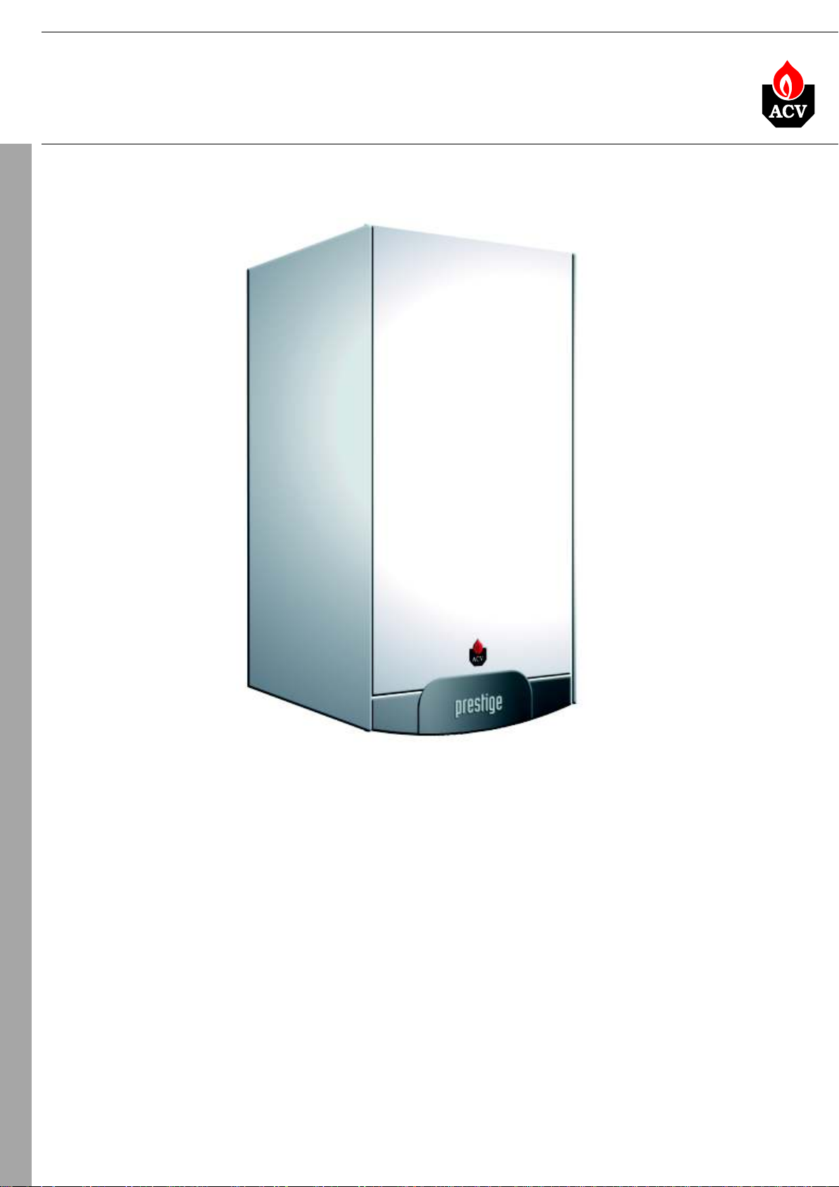
Prestige is a wall-mounted gas condensing boiler with very high efficiency. At
the heart of the Prestige is a new, specially designed stainless steel heat
exchanger, developed after intensive research and laboratory testing. Designed
using ACV’s 80 years experience in the manufacture of heating and hot water
products. Stainless steel offers very high resistance to corrosion eighter from
water or condensed combustion gases. In this unique construction combustion
gases pass downwards through the heat exchanger tubes, making maximum
use of the energy available from the combustion process. Moreover, as the
condensate runs down the heat exchanger tubes, it cleans any traces of
combustion residue, this ensures that the boiler continues to function at
maximum efficiency throughout its life.
The Prestige burner can operate for both natural gas and propane, they are
very quite with low NOx emission. An integrated weather dependent regulator
controls the burner power which increases boiler efficiency and reduces gas
consumption. The boilers are very compact and lightweight. Can be connected
in cascade to increase output or installed together with HeatMaster or ACV
tank-in-tank for hot water production. Prestige can fulfill the needs of both the
individual and highly specialised user.
®
Page 5
05
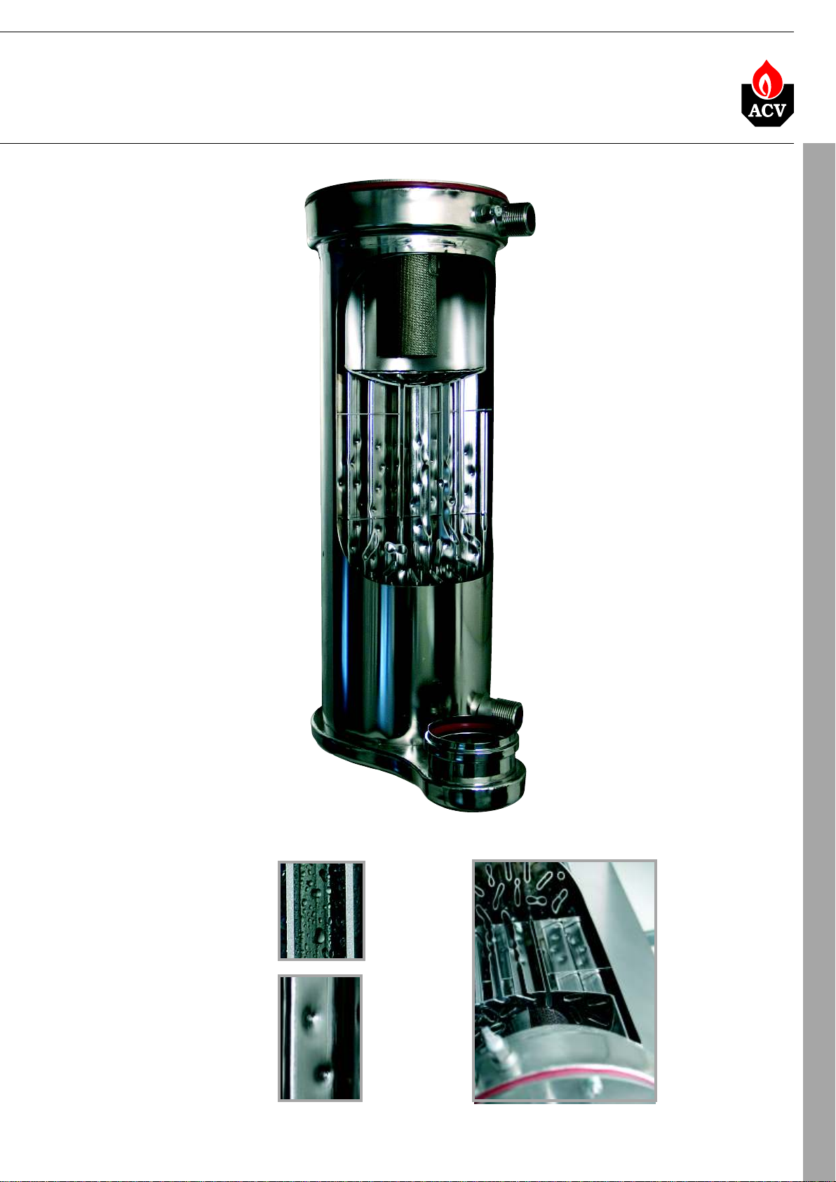
HEAT EXCHANGER
EXCELLENT RESISTANCE TO
CORROSION
Stainless steel offers a high
resistance to corrosion from the
internal primary water which could
contain system additives and
impurities. It is also resistant to the
acidity of condensate which forms in
the flue ways, and even to the
presence of sulfpher traces in natural
gas or propane.
HIGH EFFICIENCY
The stainless steel heat exchanger
flue tubes are designed to reach an
optimal heat exchange over their
entire length. The Prestige maintain
an exceptional continuous output
throuhout the life of the boiler, since
no oxidation occurs in the heat
exchanger. Furthermore the fuel
consumption of the boiler is
improved thanks to the reduced
pressure loss in the flue tubes.
LIGHTWEIGHT
Due to the exceptional corrosion
resistant properties of stainless steel,
an equivalent aluminium heat
exchanger would be much thicker
and therefore much heavier than the
stainless steel heat exchanger of the
Prestige.
excellenceinhotwaterexcellenceinhotwater
LOW MAINTENANCE
The stainless steel heat
exchanger of the Prestige is self -
cleaning, as the condensate runs
down the exchanger tubes it
cleans any possible traces of
combustion residue. This ensures
that the boiler continues to
function at maximum efficiency
throughout its life, and therefore
maintenance requirements for the
heat exchanger are reduced.
STABLE BOILER
TEMPERATURE CONTROL
Most boilers use a water tube for
the combustion process, however
the stainless steel heat
exchanger of the Prestige has
flue tubes running through the
sealed water jacket. This
increases the volume of water in
the system, the benefit is that it
allows stable temperature control
of the boiler and minimizes the
risk of overheating due to varying
water flow rates.
DESCRIPTION
Special construction of the
heat exchanger allows better
heat exchange from
combustion gases to the
water
Page 6
06
DESCRIPTION
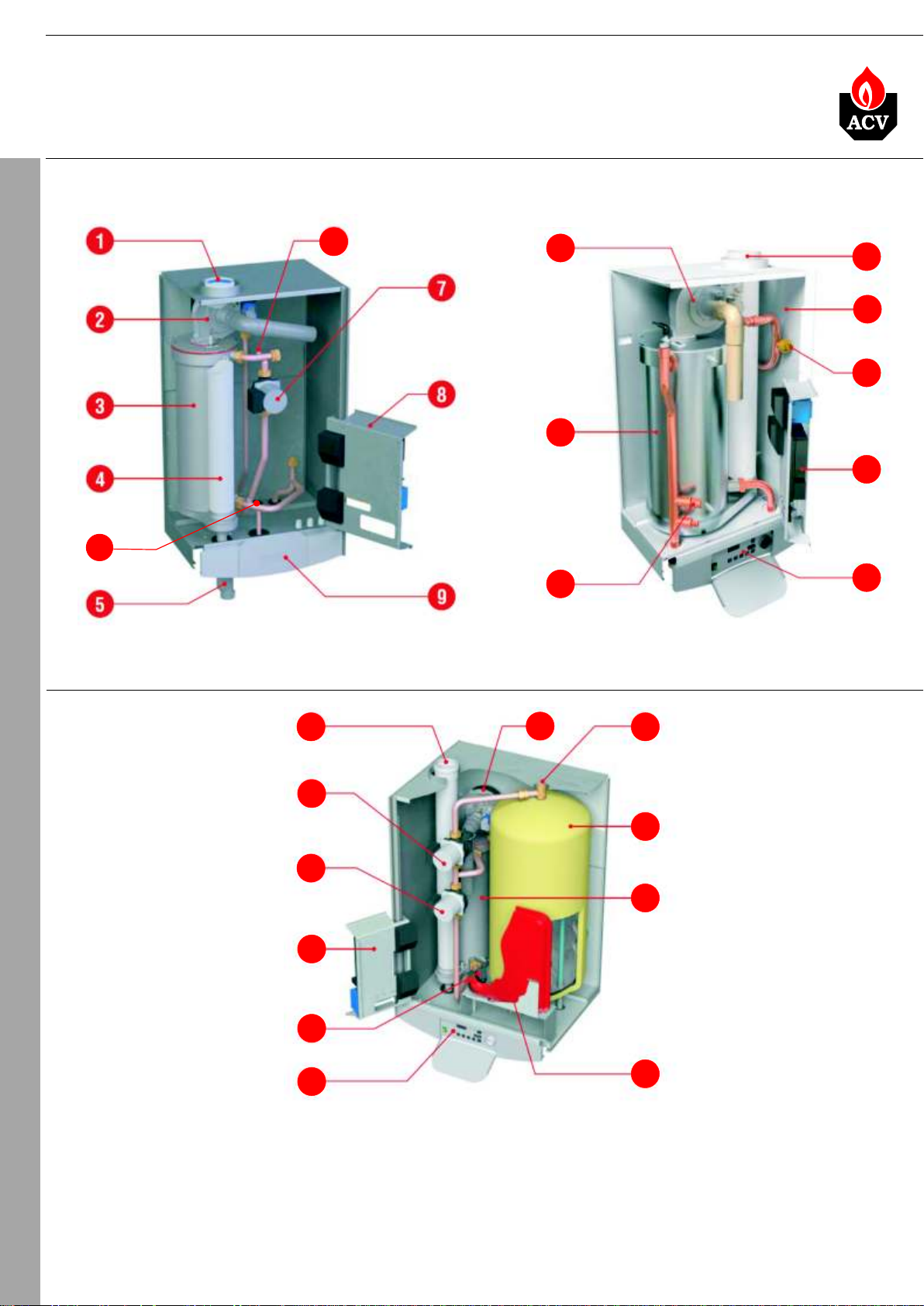
CONSTRUCTION
PRESTIGE SOLO
PRESTIGETECHNICAL
14
24 - 32 50 - 75 - 120
11
2
3
14
excellenceinhotwaterexcellenceinhotwater
1
15
6
8
9
PRESTIGE EXCELLENCE
1
10
7
8
14
9
2
11
12
3
13
LEGEND:
1. Chimney connection
2. Burner
3. Stainless steel heat exchanger
4. Flue tubes
5. Condensate trap
6. Low gas pressure switch
7. CH primary pump
8. Electrical plate
9. Control panel
10. Hot water primary pump
11. Air vent
12. Stainless steel hot water tank
13. Expansion vessel
14. Low pressure water switch
15. Casing
Page 7

07
WORKING PRINCIPLE
CONDENSATION
During natural gas or propane combustion, CO2 and water vapour is created. The temperature of
combustion gases that leave a non-condensing boiler can be more than 150 C, which means that
during stable boiler operation, water vapour will not condese. These combustion gases are hot,
and this heat is lost to the atmosphere.
The Prestige is a condensing boiler, which means that the water vapour from combustion gases
will condense and this heat will be recovered. Condensing boilers convert latent vapour energy
contained in flue gases back to water, exploiting its thermal energy and therefore reducing fuel
consumption.
This is how the standard output of a condensing boiler reaches 109% measured on the
combustion gas LHV (Low Heating Value), which immiediately translates into an energy saving of
25-30% compared to a traditional system.
Contrary to traditional boilers, a condensing boiler not only uses the heat produced in combustion
but also converts the latent heat of the vapour.
The Prestige features incredibly low emissions of nitrogen oxygen (NOx) and carbon monoxide
(CO): emissions are 30% lower than the most stringent environment protection standards.
excellenceinhot waterexcellencein hotwater
0
DESCRIPTION
OPERATION
Working principle
Pre-mixed gas and air is blown by the fan to the burner head, where it ignites on the burner tube.
The number of fan revolutions are regulated to allow for fluent power modulation of the burner.
The flue gases pass downwards through the flue tubes of the heat exchanger and in the lower part
the water vapour from flue gases is condensed, the condensate flows down to the trap below the
boiler.
Special construction of the flue tubes allows for efficient heat exchange to the water, when the
condensate flows down through the heat exchanger, it cleans it automatically. The primary water
is pumped across the heat exchanger, in the Prestige 24-32 these pumps are located under the
front casing.
The Prestige Excellence is also equipped with a 54 litre cylinder for hot water production. The
cylinder is made using ACV tank-in-tank system. You know all the advantages of ACV tank-intank system ...
Boiler management
Boiler operation is managed by the MCBA. The control manages all the gas burner and boiler
functions, including its safety parameters and flame modulation, as well as monitoring and
controlling the water temperature (outlet/inlet) and the combustion gases. It can also work as a
weather dependent regulator when the outside temperature sensor is connected.
With the MCBA you can also regulate a DHW tank or with further enhacements control multiple
heating circuits and communicate with other boilers and controls.
Page 8
08
TECHNICAL CHARACTERISTICS
TECHNICAL DATA
Fuel
Input min/max
Output min/max
Efficiency 30% (EN677)
Flue - max. pressure drop
CO in combustion gases
2
Max NOx emission
Max CO emission
G20 gas flow rate
G31 gas flow rate
Weight
Heating circuits
Heating connections
Hot water connections
Max. operating temperature
PRESTIGETECHNICAL
Total capacity
Boiler water capacity
Hot water tank capacity
Capacity of the expansion vessel
Max. operating pressure heating/hot water
Hot water peak flow Dt=30 C
Hot water peak flow Dt=25 C
Electrical connection
Supply voltage
Maximum absorbed electrical power
Class
0
0
Type
kW
kW
%
max Pa
%
mg/kWh
mg/kWh
3
m /h
3
m /h
kg
0
litr
litr
litr
bar
l/min
l/min
V/Hz
IP
Prestige Solo
24
G20, G31
5,9/24*
5,8/23,4*
109
130
max 9,3*
66*
45/20*
2,5
0,98**
48
1”
-
C
A
90
8
8
-
-
3/-
-
-
230/50
0,8
30
Prestige Excellence
24
G20, G31
5,9/24*
5,8/23,4*
109
130
max 9,3*
66*
52/20*
2,5
0,98**
92
1”
3/4”
90
70
16
54
1x12 litr
3/10
17,5
21,0
230/50
0,8
30
Prestige Solo
32
G20, G31
5,9/32*
5,8/31,0*
109
130
max 9,3*
66*
45/20*
3,4
1,3**
48
1”
-
90
8
8
-
-
3/-
-
-
230/50
0,8
30
[*] gaz G20 values
**] Prestige with propane has P in the name
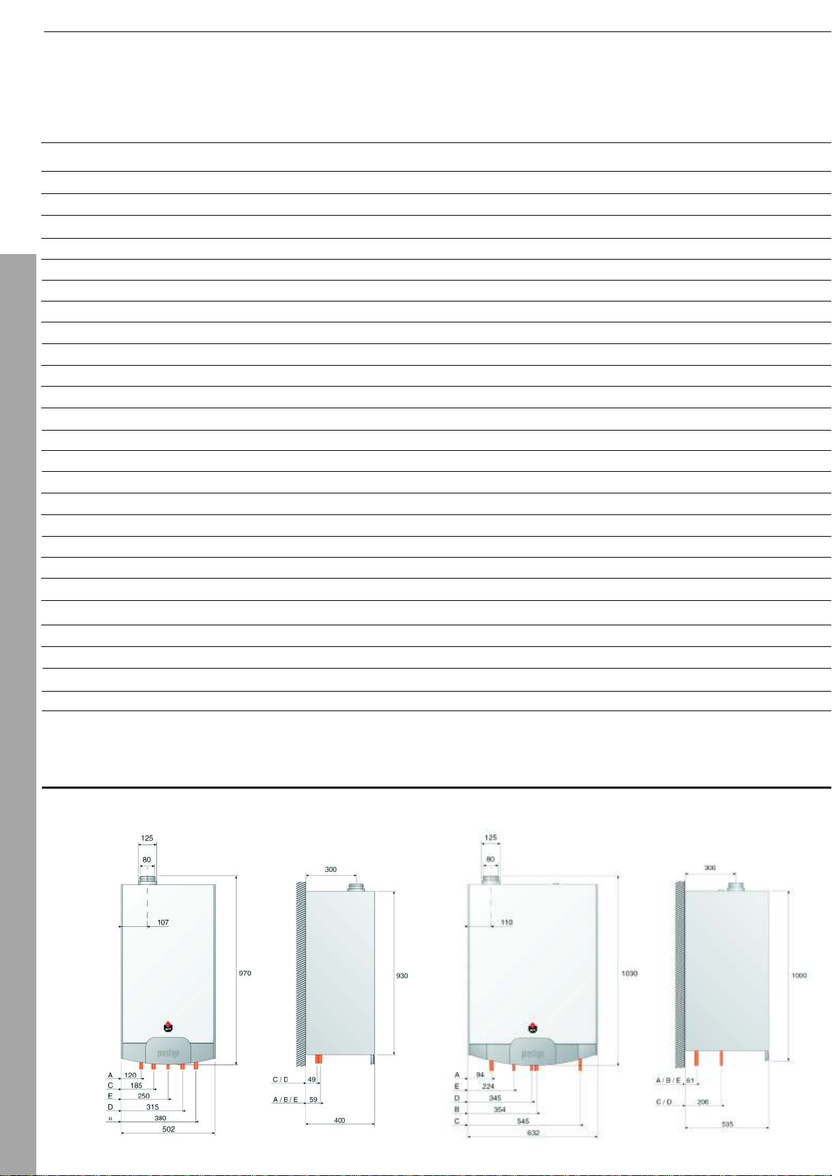
DIMENSIONS
PRESTIGE SOLO 24 - 32
PRESTIGE EXCELLENCE 24 - 32
Page 9
09
Prestige Excellence
32
G20, G31
5,9/32*
5,8/31,0*
109
130
max 9,3*
66*
52/20*
3,4
1,3**
92
1”
3/4”
90
70
16
54
1x12 litr
3/10
22,4
27,0
230/50
0,8
30
Prestige Solo
50
G20, G31
15/49,9*
14,7/48,4*
107,8
150
max 9,4*
66*
45/20*
5,3
2,0**
58
1 1/4”
90
20
20
-
4/-
-
-
230/50
1,1
30
Prestige Solo
75
G20, G31
18,3/72*
17,9/69,9*
107,8
150
max 9,4*
62*
52/20*
7,6
2,8**
58
1 1/4”
90
17
17
-
-
4/-
-
-
230/50
1,1
30
Prestige Solo
120
G20, G31
45/80-126*
36,3/78,1-116,6*
150
max 9,5*
47*
106/*
12,7
5,1**
83
1 1/2”
90
28
28
-
-
4/-
-
-
230/50
1,1
30
TECHNICAL DATA
Type
kW
kW
%
max Pa
%
Efficiency 30% (EN677)
Flue - max. pressure drop
CO in combustion gases
2
mg/kWh
mg/kWh
3
m /h
3
m /h
kg
Hot water connections
0
C
Max. operating temperature
litr
litr
litr
Hot water tank capacity
Capacity of the expansion vessel
Max. operating pressure heating/hot water
bar
l/min
l/min
Hot water peak flow Dt=30 C
Hot water peak flow Dt=25 C
Electrical connection
V/Hz
A
Maximum absorbed electrical power
IP
Input min/max
Output min/max
Max NOx emission
Max CO emission
G20 gas flow rate
G31 gas flow rate
Heating circuits
Heating connections
Total capacity
Boiler water capacity
Supply voltage
Fuel
Weight
0
0
Class
TECHNICAL CHARACTERISTICS
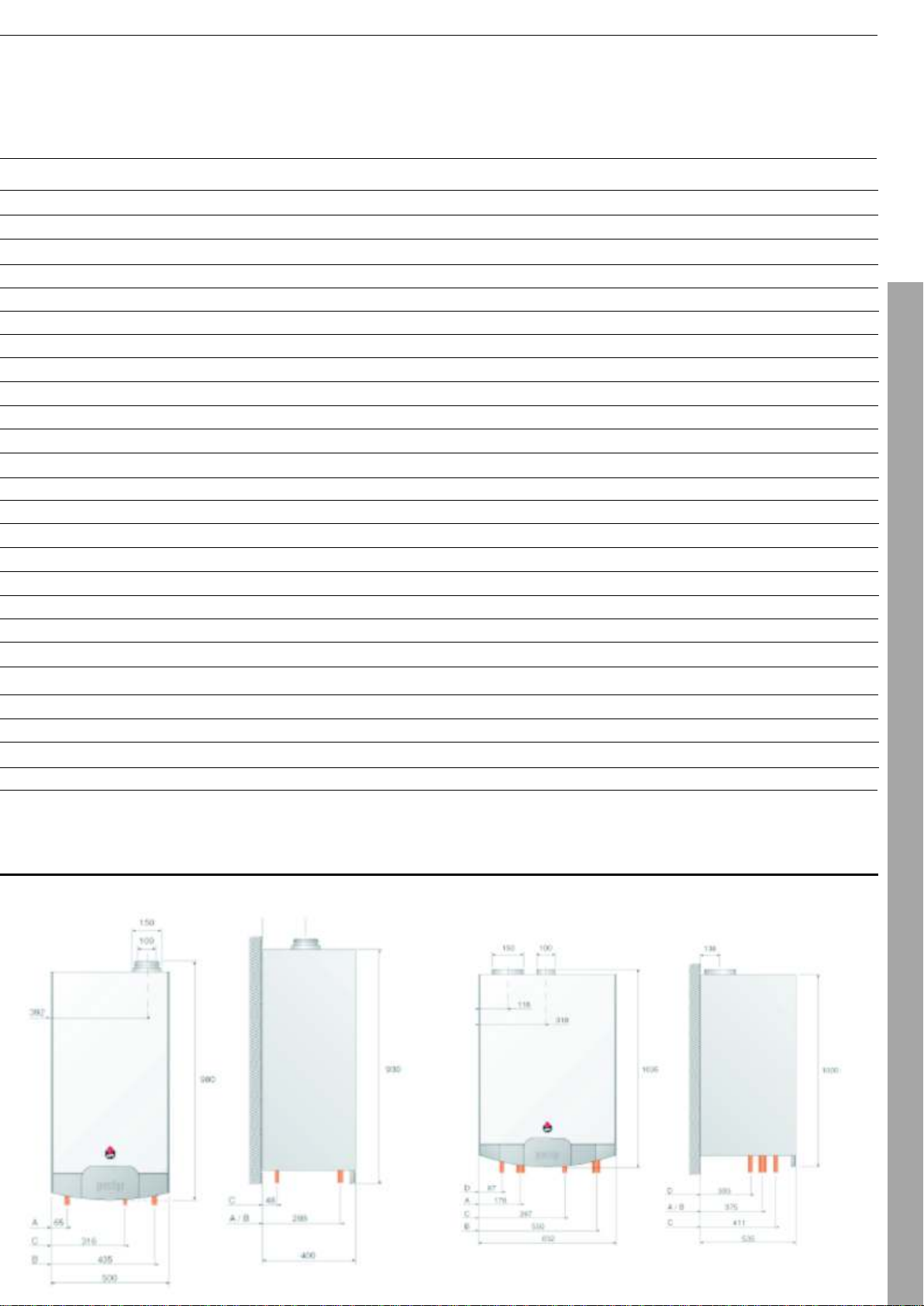
PRESTIGE SOLO 50 - 75
DIMENSIONS
PRESTIGE SOLO 120
Page 10
10
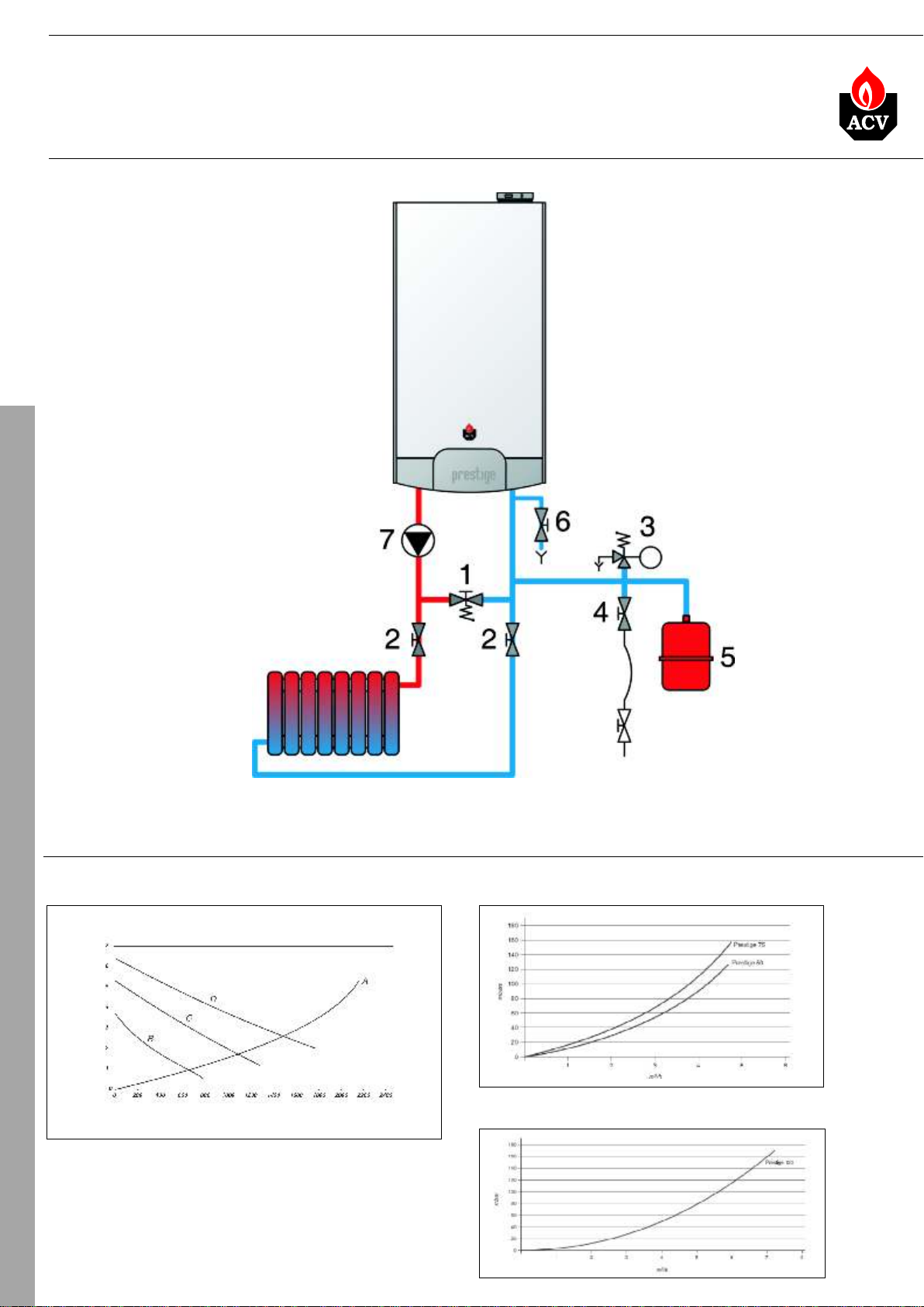
CONNECTIONS
HEATING CONNECTIONS
1. By-pass with differential pressure valve
2. Isolating valve, heating system
3. Safety valve calibrated to 3 bar, with
pressure gauge
4. System filling valve
5. Expansion vessel
6. Drain cock
7. Loading pump, heating system
excellenceinhot waterexcellencein hotwater
PRESTIGETECHNICAL
DIAGRAMS OF PRESSURE DROP - HEATING SIDE
PRESTIGE 24 - 32 SOLO PRESTIGE 50 - 75 SOLO
Pressure (mH2O)
Flow (litres/hour)
A = pressure drop of the boiler
B = pressure available circulator on 1
C = pressure available circulator on 2
D = pressure available circulator on 3
PRESTIGE 120 SOLO
Page 11
11
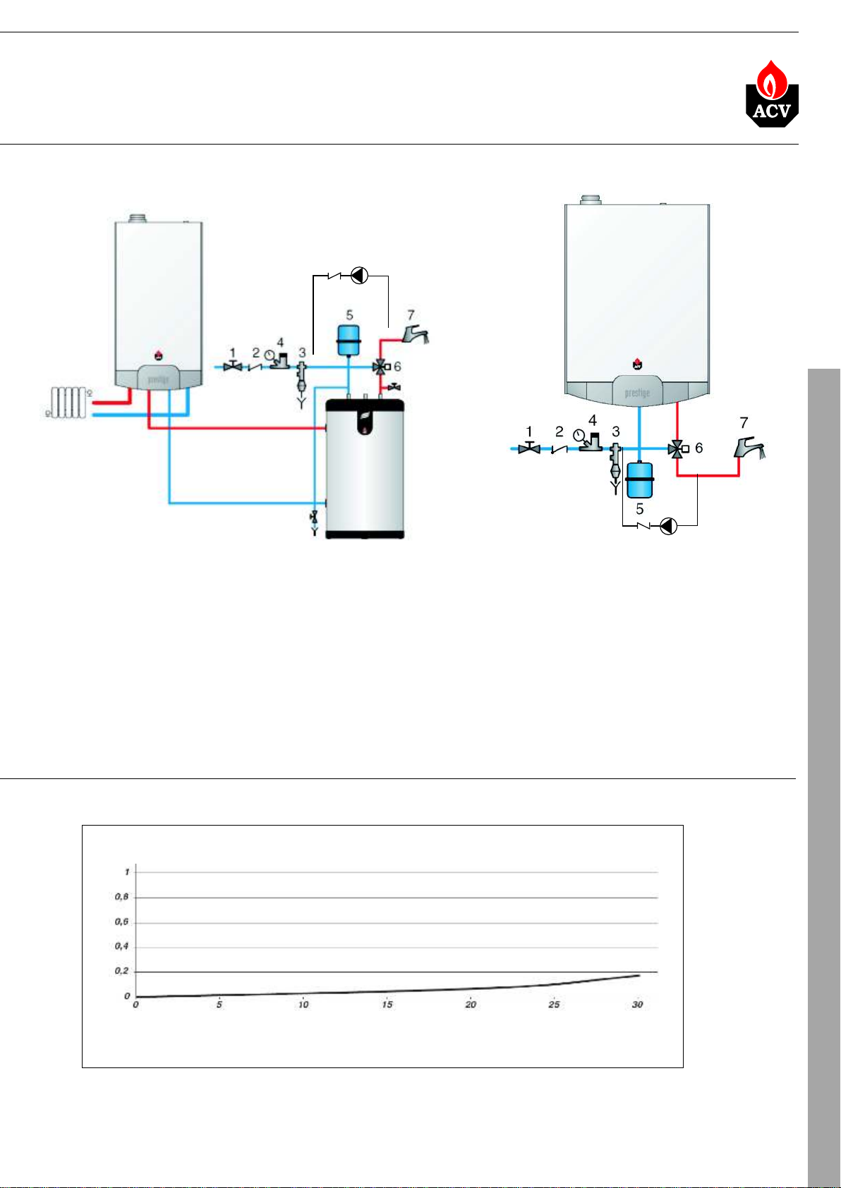
DOMESTIC HOT WATER CONNECTIONS
PRESTIGE SOLO
2
excellenceinhot waterexcellencein hotwater
PRESTIGE EXCELLENCE
8
CONNECTIONS
8
2
1. Isolating valve
2. Non-return valve
3. Safety valve
4. Pressure reducing valve (4 bar)
5. Expansion vessel
6. Thermostating mixing valve
7. Hot outlet
8. Circulating pump
DIAGRAMS OF PRESSURE DROP - DOMESTIC HOT WATER SIDE
Pressure drop (bar)
A
Volume of domestic hot water (litres/min)
A = pressure drop on the domestic hot water side - Prestige Excellence
Page 12
12
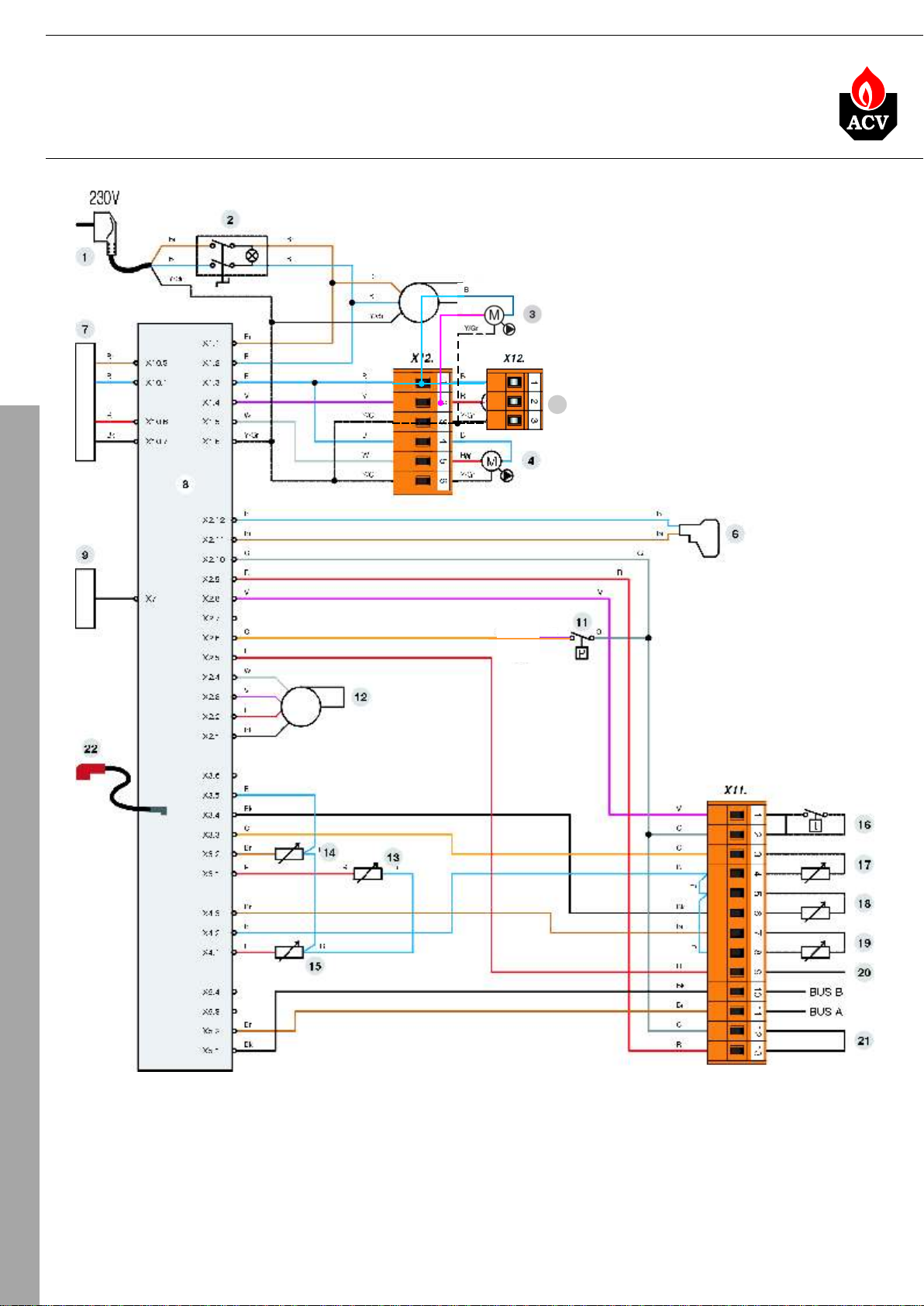
CONNECTIONS
WIRING DIAGRAM - PRESTIGE 24 - 32
excellenceinhot waterexcellencein hotwater
V
23
W
PRESTIGETECHNICAL
1. 230V connection cord
2. On/off switch
3. Heating pump
4. Hot water pump - Excellence
(Solo - option)
5. Burner
6. Gas valve
7. Transformer 230V-24V
8. MCBA
9. Screen
11. Water pressure switch
12. Burner connection
13. NTC1 flow sensor
14. NTC2 return sensor
15. NTC5 flue gas temperature sensor
16. Room thermostat (option)
17. NTC3 hot water sensor - Excellence
(Solo - option)
18. NTC4 outdoor temperature sensor
(option)
19. NTC6 second circuit sensor
(option)
20. Zero volt of 24V circuit
21. External safety thermostat
(RAM-option)
22. HT lead for ignition electrode
23. Heating pump connection of the
direct circuit (2 heating circuits)
Page 13
13
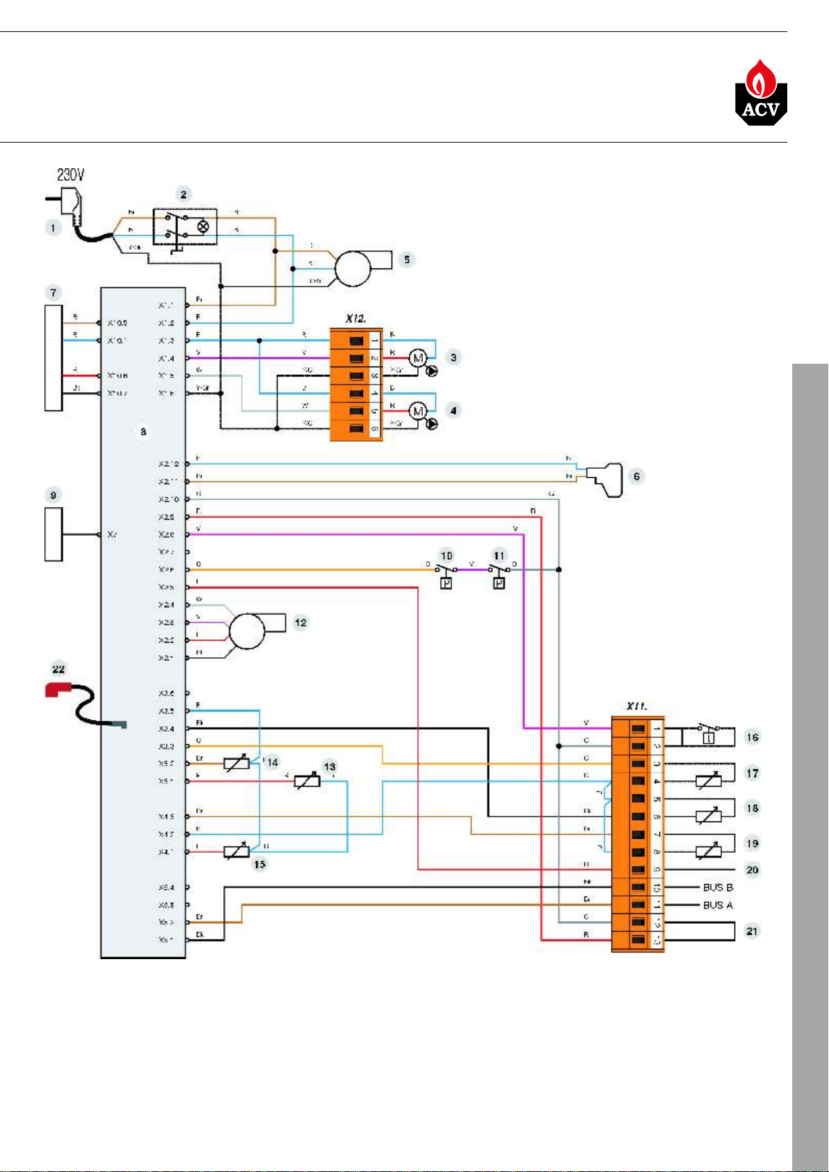
WIRING DIAGRAM - PRESTIGE 50 - 75
excellenceinhot waterexcellencein hotwater
PODŁĄCZENIA
CONNECTIONS
1. 230V connection cord
2. On/off switch
3. Heating pump
4. Hot water pump (option)
5. Burner
6. Gas valve
7. Transformer 230V-24V
8. MCBA
9. Screen
10. Gas pressure switch
11. Water pressure switch
12. Burner modulation
13. NTC1 flow sensor
14. NTC2 return sensor
15. NTC5 flue gas temperature sensor
16. Room thermostat (option)
17. NTC3 hot water sensor (option)
18. NTC4 outdoor temperature sensor
(option)
19. NTC6 second circuit sensor
(option)
20. Zero volt of 24V circiut
21. External safety thermostat
(RAM-option)
22. HT lead for ignition electrode
Page 14
14
14
CONNECTIONS
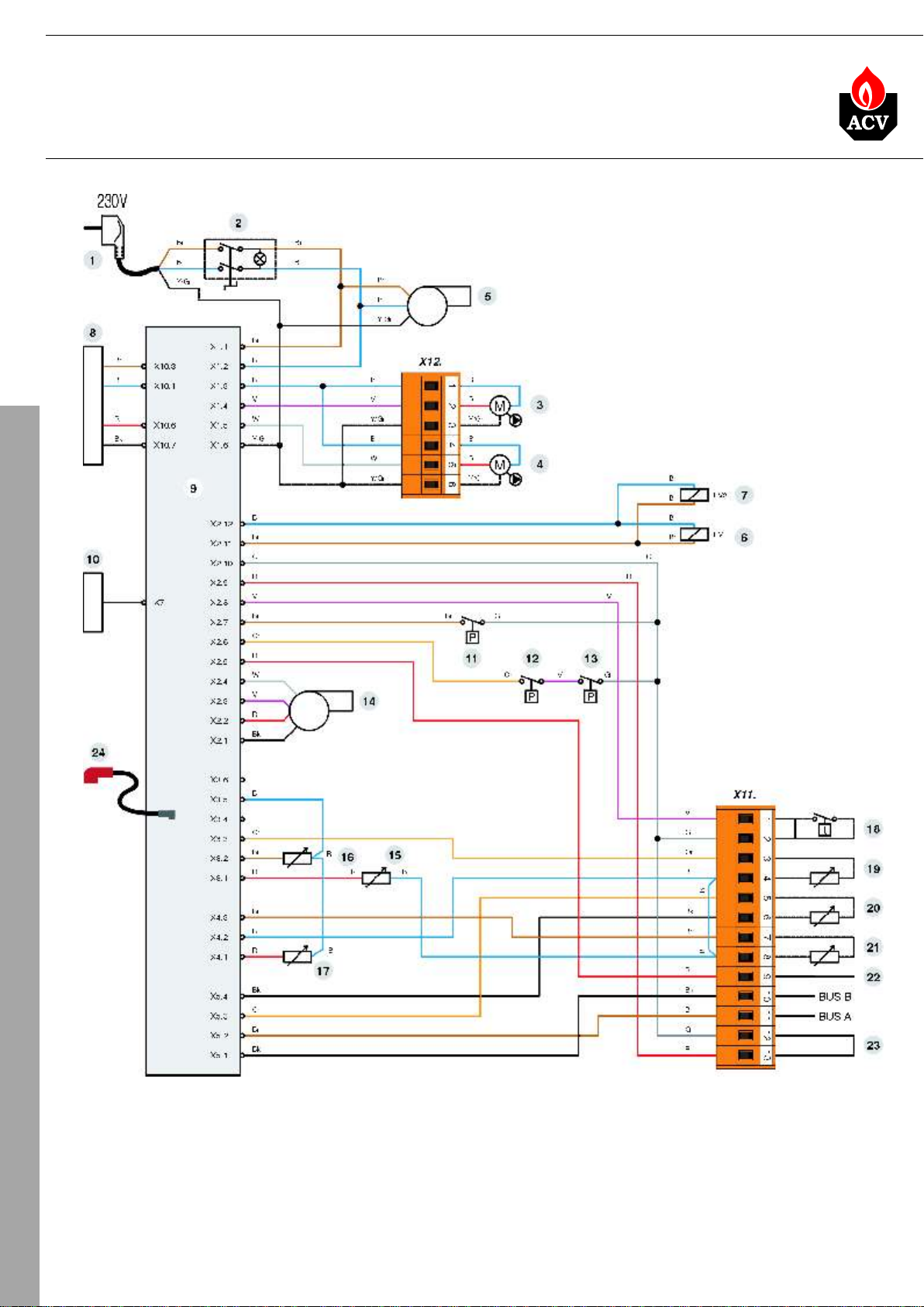
WIRING DIAGRAM - PRESTIGE 120
excellenceinhot waterexcellencein hotwater
excellenceinhot waterexcellencein hotwater
PRESTIGETECHNICAL
1. 230V connection cord
2. On/off switch
3. Heating pump
4. Hot water pump
5. Burner
6. Gas valve 1
7. Gas valve 2
8. Transformer 230V-24V
9. MCBA
10. Screen
11. Air pressure switch
12. Gas pressure switch
13. Water pressure switch
14. Burner modulation
15. NTC1 flow sensor
16. NTC2 return sensor
17. NTC5 flue gas temperature sensor
18. Room thermostat (option)
19. NTC3 hot water sensor (option)
20. NTC4 outdoor temperature sensor
(option)
21. NTC6 second circuit sensor
(option)
22. Zero volt of 24V circuit
23. External safety thermostat
(RAM-option)
24. HT lead for ignition electrode
Page 15
15
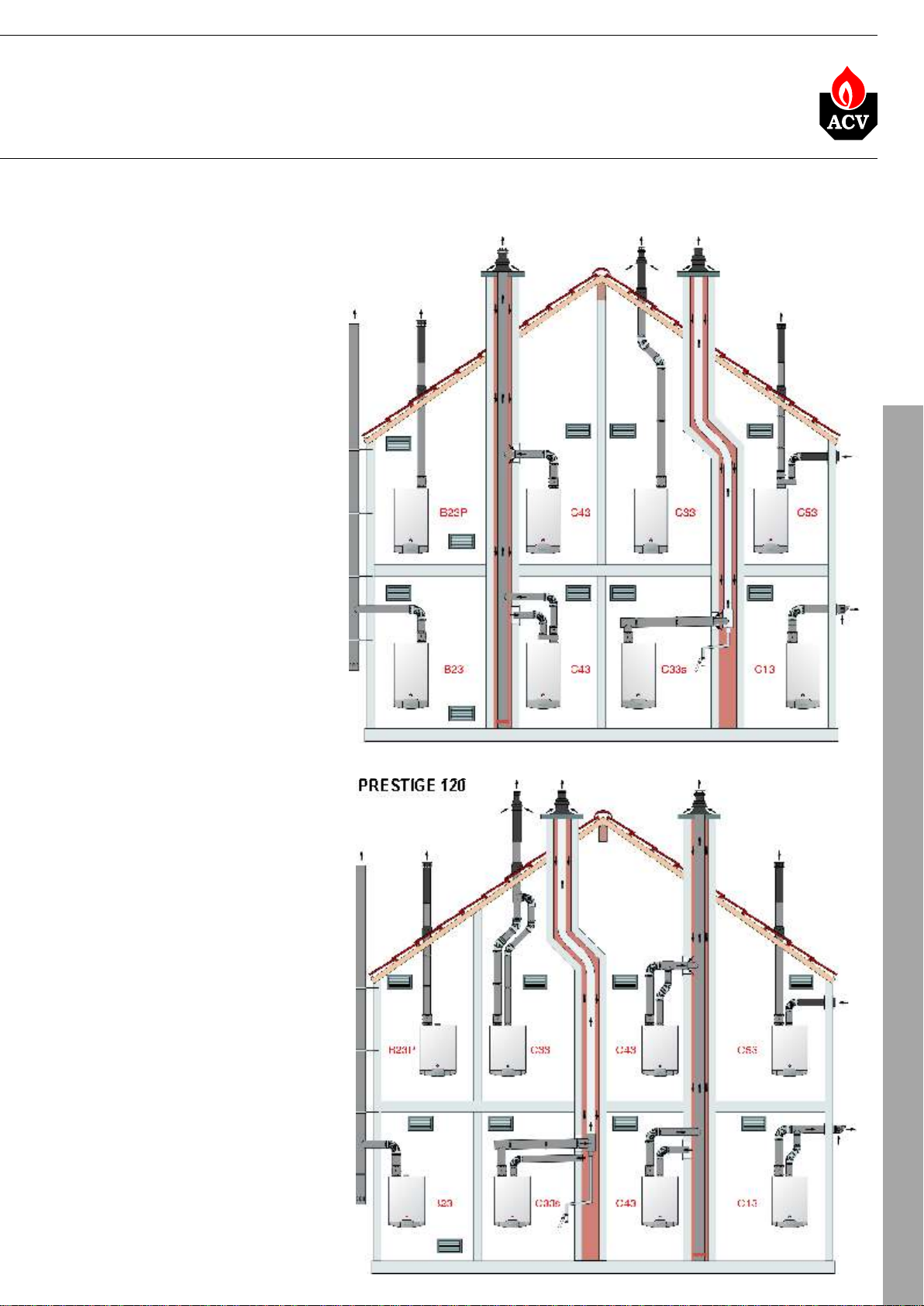
CHIMNEY CONNECTIONS
B - connection to an exhaust duct
23
venting the combustion products
outside of the installation area,
with the combustion air being
drawn directly from this area.
B - connection to an exhaust
23P
system of the combustion
products designed to operate with
positive pressure.
C - appliance connection with a
13
horizotal balanced flue/onlet air
ducts to outside atmosphere.
C - appliance connection with a
33
vertical balanced flue/inlet air
ducts to outside atmosphere.
C - connection with an individual
33S
system of which the exhaust duct
for the combustion products is
installed in an exhaust pipe that is
part of the building. The
appliance, the exhaust duct and
the terminal units are certified as
an assembly that cannot be
dissociated.
excellenceinhot waterexcellencein hotwater
PRESTIGE 24 - 32 - 50 - 75
CONNECTIONS
C - connection by two ducts to a
43
collective duct system serving
more than one appliance; this
system of collective ducts features
two ducts connected to a terminal
unit that simultaneously intakes
fresh combustion air and
discharges the combustion
products outside through
openings that are either
concentric or close enough
together to be subjected to similar
wind conditions. “U” duct system.
C - appliance connection to an
53
non balanced flue/inlet air ducted
system.
Note: maximum flow resistance is
shown in the technical manual for
the boiler.
PRESTIGE 120
Page 16

16
BURNER, REGULATOR, CASCADES
BURNER
THE INTELIGENT ACV
BURNER
ECONOMIC OPERATION
QUIET OPERATION OF
THE PREMIX BURNER
REGULATOR ACV MCBA
PRESTIGETECHNICAL
excellenceinhot waterexcellencein hotwater
The innovative gas premix burner in the Prestige has been designed to provide high efficiency
and clean combustion. Premix technology makes it possible to perfectly mix gas and air before
combustion, in all operating conditions and to guarantee optimal efficiency with no hazardous
emissions. In addition, the burner modulates from about 25% to 100% of nominal capacity to
adapt power continously to the current heat requirement: operating cycles are longer, resulting in
less starts and stops, less harmful emissions, less maintenance and longer lifetime of the burner.
Moreover, the burner head is covered with a metalic fibre engineered both to withstand high
thermal loads and to reach near perfect radiant combustion mode at low load.
The Prestige Solo is equipped with an inlet temperature sensor, an outlet temperature sensor
and a flue gas temperature sensor. In addition the Prestige Excellence is equipped with a hot
water temperature sensor. All the sensor information is transmitted to the MCBA that will
precisely adapt the power of the burner for the most efficient operation possible.
ACV has adopted BG 2000 M burners for Prestige boilers. This is a safe and quiet air/gas premix
burner that limits polluting emissions (NOx and CO) to incredibly low levels. Although thoroughly
modern, the ACV BG 2000 M burner uses proven technology and widely distributed standard
components.
The casing of the Prestige is made from insulated steel that completely encloses the burner,
guaranteeing extremely quiet operation. Also, the heat emitted by the heat exchanger is
absorbed into the combustion air, which improves efficiency and prevents heat radiation.
Prestige is equipped with an integrated MicroproCessor Burner Automate (MCBA) that controls
the safety-functions of the boiler and offers a wide band of built-in temperature controls, which
can be selected and adapted through a number of parameters, with different access levels (enduser, service engineer, ...)
If an outside sensor is connected to the MCBA it becomes a complete weather-dependent
control, with the possibility of having night set-back if an external clock is used.
An outside sensor connected to the MCBA will determine the basic flow temperature. If the room
thermostat contact remains closed for a longer period, the flow temperature setting will be
increased by 10 C until the desired room temperature is achieved. In this way an auto-adaptive
heating curve is achieved which combines the advantages of a fast heat-up curve with the
temperature stability of a standard weather-dependent control.
o
CASCADE OF BOILERS
EXCELLENT REASONS
TO INSTALL A
CASCADE
BALANCED HEADER
Efficiency: a cascade system allows modulation of the heating power, from the minimum output
of one boiler up to the maximum output of all the boilers. Which, in the case of a four-boiler
cascade, gives a modulation ratio of 16:1.
Back up: the ACV cascade controllers optimise the potential of the available boilers, if one of the
boilers fail, the controller simply adjust the power of the remaining boilers to compensate.
Easy commissioning: one, two, three or four boilers, the commissioning procedure is the
same, simple and easy when undertaken by a qualified engineer.
Easy maintenance: any one boiler in a cascade can be serviced and maintained easily whilst
the other boilers are operational. This enables the servicing to be carried out at any time of the
year and not just during the traditional summer shut down period.
A wide spectrum of modulation reduces number of starts in comparision to a single more
powerful boiler, as a result less fuel is used. The electrical energy used to transport heating water
by the boilers is also reduced as the main regulator decides how many boilers need to operate
and how many pumps are required.
To connect one or more boilers with one or more heating circuits, the balanced header can be
installed. It removes the most frequent causes of faults in heating systems and allows for stable
operation without need to balance the flow. Boiler or heating circuit pump start/stop has no effect
on other devices or regulation systems. This configuration makes the operation of the whole
system very flexible, because the volume of the water in heating generators is not in direct
conjunction with the water volume in heating circuits. For correct operation of the balanced
header at maximum power consumption, the flow of the water in primary (boilers) circuit has to
be at a higer level than the flow in the secondary (heating) circuits.
In addition, the balanced header also operates as a trap. Sediment from the heating circuits falls
to the lowest part of the header and cannot contaminate the boilers.
Page 17

SAMPLES OF INSTALLATIONS
17
LEGEND
excellenceinhot waterexcellencein hotwater
PICTURE CODE NAME MARK
10800018
5476G003
10510100
537D3040
10510900
ROOM THERMOSTAT ACV 22
Installed inside the building on the wall. Controls room set temperature.
Operates with MCBA. Connected to the boiler terminals 1-2 instead of the bridge.
HOT WATER SENSOR
Senses the temperature in the external hot water tank. Controls set temperature.
Connected to the boiler terminals 3-4
OUTSIDE TEMPERATURE SENSOR NTC 4 (AF 120)
Installed on the external wall of the building. Controls outside temperature and regulates
boiler operation. Connected to the MCBA terminals 5-6.
CONTACT SENSOR NTC 6
Installed on the outlet of controlled circuit. Allows weather dependent regulation.
Connected to the boiler terminals 7-8.
CONTACT SENSOR RAM 5109
Installed on the outlet of the floor heating circuit, to protect pipe work overheating.
Connected to the boiler terminals 12-13.
NTC 3
A
B
C
D
E
10800095
10800119
10800034
10800030
10800121
AM 3 - 11 MODULE
Controls the second heating circuit - communicates directly with the MCBA. Operates
with room thermostat.
ZMC -1 MODULE
Controls the second heating circuit - alarm contact - operates only in cojunction with the
Room Unit RSC. Needs RMCI installed directly in MCBA.
ROOM UNIT RSC
Room regulator, controls heating and hot water production, installed inside of the
building on the wall. Supplied with outside temperature sensor. Allows heating curve
regulation, room and hot water temperature. Displays all temperatures. Connected to
the terminals 10-11 of the boiler terminal block.
CONTROL UNIT
Regulates one or more boiler (cascade of max 8 boilers) Prestige with modulating
burners. Allows control of 3 heating circuits (2 mixed, 1without mixer) and hot water
production. Equipped with 2 outputs and 3 programmable inputs, allowing solar system
and solid fuel boiler regulation. Installed in the wall mounting socket.
WALL MOUNTING SOCKET FOR THE CONTROL UNIT
F
G
H
SAMPLES OF INSTALLATIONS
I
J
10800057
10800036
INSTALLER TERMINAL BLOCKS FOR THE CONTROL UNIT
CLIP-IN INTERFACE RMCI
Installed directly in the MCBA. Enables communication between the boiler MCBA, the
Room Unit and the Control Unit.
K
L
Page 18

18
SAMPLES OF INSTALLATIONS
LEGEND
PICTURE CODE
10800108
10800044
10800045
10800120
10800056
excellenceinhot waterexcellencein hotwater
NAME
OUTSIDE TEMPERATURE SENSOR AF 200
Installed on the oustide north wall of the building. Operates with Control Unit. Connected
to terminals 26-23 of Control Unit terminal block.
POCKET SENSOR KVT
Installed in the hot water tanks and in the balanced header. Connected to the Control Unit.
CONTACT SENSOR VF 202
Installed on the outlet of the mixed heating circuit. Operates with the ZMC-1 module and
the Control Unit.
ROOM TEMPERATURE SENSOR RFF
Operates with the Control Unit. Can be mounted on every heating circuit. Connected to
Control Unit terminals 24-25.
ZONE UNIT RS
Shows internal temperature and allows for remote control of 1 heating circuit.
Communicates with the Control Unit. For 3 heating circuits - max 3 Zone Units. Allows
correction of the heating curve, temperatures and shows information from installed
sensors. Connected to the Control Unit terminals 24-25.
MARK
M
N
O
P
R
PRESTIGETECHNICAL
002202
10800104
10800105
10800142
10800107
SOLAR SENSOR PT 1000
Installed in the solar collector. Controls temperature of the solar system. Co-operates
with the Control Unit that regulates the solar system pump group. Connected to the
Control Unit terminals 34-23.
COLLECTOR 2 CIRCUITS DN 32
Installed directly under the boiler. Allows connection of 2 heating circuits. Internal
regulation of the by-pass allows it to become a balanced header.
COLLECTOR 3 CIRCUITS DN 32
Installed directly under the boiler. Allows connection of 3 heating circuits. Internal
regulation of the by-pass allows it to become a balanced header.
CONNECTION KIT DN 32 TO THE MANIFOLD
Includes: two flexible 1 1/2” hoses and 1 1/4” reduction fittings.
HIGH TEMPERATURE KIT DN 32
Installed to the collector under the boiler. Supplies high temperature circuit or water tank
primaries. Includes: 1 circulation pump, 2 isolating valves, check valve, 2 thermometers.
S
T
U
V
W
10800106
10800019
LOW TEMPERATURE KIT DN 32
Installed to the collector under the boiler. Supplies low temperature circuit and controls
its temperature. Includes: 1 circulation pump, 2 isolating valves, check valve, 2
thermometers and the 3-way valve with the integrated by-pass.
SERVOMOTOR SQK 349
Installed on the 3-way mixing valve of the low temperature kit. Controls the temperature
of the low temperature circuit.
X
Y
Page 19

excellenceinhot waterexcellencein hotwater
PICTURE CODE NAME MARK
19
10800161
10800162
10800167
10800168
10800171
10800172
10800169
10800170
BALANCED HEADER DN 80
BALANCED HEADER DN 100
Three functions in one device: air separator, hydraulic separator and dirt tap.
the most frequent causes of faults in heating systems. Includes flange connections,
automatic air vent, sludge cock, temperature sensor tube and EPP insulation
KIT COLLECTOR DN 80 FOR 2 BOILERS
Two connections (flow and return) with isolating valves and pumps. Allows for quick
installation of 2 boilers in cascade. Possible extenstion.
KIT COLLECTOR DN 80 FOR 3 BOILERS
Two connections (flow and return) with isolating valves and pumps.
installation of 3 boilers in cascade. Possible extenstion.
CONNECTION KIT BOILER - COLLECTOR DN 80
Couplings DN 32 (L=100 and 135 mm) with unions and gaskets to connect boiler with
the collector kit.
CONNECTION KIT BOILER - COLLECTOR DN 100
Couplings DN 32 (L=170 and 320 mm) with unions and gaskets to connect boiler with
the collector kit.
FLOOR COLLECTOR SUPPORT CASCADE DN 80
FLOOR COLLECTOR SUPPORT CASCADE DN 100
Removes
.
Allows for quick
X1
X2
X3
X4
X5
X6
10800164
ADAPTOR KIT DN 80 - DN 100
Adaptor to connect the collector kit DN 80 to the balanced header DN 100.
X7
SAMPLES OF INSTALLATIONS
Page 20

20
SAMPLES OF INSTALLATIONS
SCHEME 1:
excellenceinhot waterexcellencein hotwater
PRESTIGE 50 - 75 SOLO FOR 1 HEATING CIRCUIT AND HOT WATER PRODUCTION, WEATHER DEPENDENT
REGULATION BY THE BOILER MCBA AND THE ROOM THERMOSTAT.
C
A
B
W
PRESTIGETECHNICAL
List of elements
Electrical connection schematic
Mark
A
B
C
T
W
V
Code
10800018
5476G003
10510100
10800104
10800107
10800142
T
W
Name of the element
Room thermostat
Hot water sensor NTC 3
Outside temperature sensor NTC 4
Collector 2 circuits DN 32
High temperature kit DN 32
Connection kit DN 32 to the manifold
Quantity
1
1
1
1
2
1
W
W
ABC
Connect room thermostat instead
of the bridge 1-2
Page 21

21
SCHEME 2:
excellenceinhot waterexcellencein hotwater
PRESTIGE 50 - 75 SOLO FOR 1 HEATING CIRCUIT AND HOT WATER PRODUCTION, WEATHER DEPENDENT
REGULATION BY THE BOILER MCBA AND THE ROOM UNIT
C
H
L
B
W
T
List of elements
Mark
B
C
H
L
T
W
V
Electrical connection schematic
Code
5476G003
10510100
10800034
10800036
10800104
10800107
10800142
W
Name of the element
Hot water sensor
NTC 3
Outside temperature sensor NTC 4 (AF 120)
Room Unit
Clip-in interface RMCI
Collector 2 circuits DN 32
High temperature kit DN 32
Connection kit DN 32 to the manifold
Quantity
1
1
1
1
1
2
1
SAMPLES OF INSTALLATIONS
W
W
C
B
H
Page 22

22
SAMPLES OF INSTALLATIONS
SCHEME 3:
excellenceinhot waterexcellencein hotwater
PRESTIGE 50 - 75 SOLO FOR 2 HEATING CIRCUITS AND HOT WATER PRODUCTION, REGULATED BY THE
BOILER MCBA AND THE AM 3-11 MODULE
C
A
F
D
B
W
X
W
V
U
List of elements
PRESTIGETECHNICAL
Mark
A
B
C
D
E
F
U
W
X
V
Y
Code
10800018
5476G003
10510100
537D3040
10510900
10800095
10800105
10800107
10800106
10800142
10800019
Y
Name of the element
Room thermostat
Hot water sensor NTC 3
Outside temperature sensor NTC 4 (AF 120)
Contact sensor NTC 6
Contact sensor RAM 5109 (for floor heating)
AM 3-11 module
Collector 3 circuits DN 32
High temperature kit DN 32
Low temperature kit DN 32
Connection kit DN 32 to the manifold
Servomotor SQK 349
Quantity
1
1
1
1
1
1
1
2
1
1
1
Page 23

Electrical schematic
23
excellenceinhot waterexcellencein hotwater
A
B
C
D
E
W
SAMPLES OF INSTALLATIONS
W
AM 3-11 module and low temperature kit
Y
F
X
MCBA
Page 24

24
SAMPLES OF INSTALLATIONS
SCHEME 4:
excellenceinhot waterexcellencein hotwater
PRESTIGE 50 - 75 SOLO FOR 2 HEATING CIRCUITS AND HOT WATER PRODUCTION, REGULATED BY THE
BOILER AUTOMATE MCBA AND THE ZMC-1 MODULE
C
H
E
G
O
W
B
L
List of elements
PRESTIGETECHNICAL
Mark
B
C
E
G
H
E
L
O
U
V
W
X
Y
Code
5476G003
10510100
10510900
10800119
10800034
10800036
10800045
10800105
10800142
10800107
10800106
10800019
X
Y
W
Name of the element
Hot water sensor
NTC 3
Outside temperature sensor NTC 4 (AF 120)
Contact sensor RAM 5109 (for floor heating)
ZMC - 1 module
Room Unit
Clip-in interface RMCI
Contact sensor VF 202
Collector 3 circuits DN 32
Connection kit DN 32 to the manifold
High temperature kit DN 32
Low temperature kit DN 32
Servomotor SQK 349
V
U
Quantity
1
1
1
1
1
1
1
1
1
2
1
1
Page 25

Electrical schematic
25
excellenceinhot waterexcellencein hotwater
B
C
H
E
E
Y
X
SAMPLES OF INSTALLATIONS
W
G
O
W
Page 26

26
SAMPLES OF INSTALLATIONS
SCHEME 5:
excellenceinhot waterexcellencein hotwater
PRESTIGE 50 - 75 SOLO FOR 2 HEATING CIRCUITS AND HOT WATER PRODUCTION, REGULATED BY THE
CONTROL UNIT.
EM
O O
I
N
W
X
X
N
L
V
U
List of elements
PRESTIGETECHNICAL
Mark
I
J
L
EM
N
O
P
R
U
V
Y
W
X
Y
Code
10800030
10800121
10800036
10800108
10800044
10800045
10800120
10800056
10800105
10800142
10800107
10800106
10800019
Y
Y
Name of the element
Control Unit
Wall mounting socket for the Control Unit
Clip-in interface RMCI
Outside temperature sensor AF 200
Pocket sensor KVT
Contact sensor VF 202
Room temperature sensor RFF
or
Zone Unit
Collector 3 circuits DN 32
Connection kit DN 32 to the manifold
High temperature kit DN 32
Low temperature kit DN 32
Servomotor SQK 349
Quantity
1
1
1
1
2
2
0 (max 2)
0 (max 2)
1
1
1
2
2
Page 27

Electrical schematic
27
excellenceinhot waterexcellencein hotwater
Wall mounting
socket for the
Control Unit
SAMPLES OF INSTALLATIONS
Bolier 1
PRESTIGE
Page 28

28
SAMPLES OF INSTALLATIONS
SCHEME 6:
excellenceinhot waterexcellencein hotwater
PRESTIGE 50 - 75 - 120 SOLO WITH SOLAR SYSTEM AND SLME CYLINDER FOR 2 HEATING CIRCUITS AND HOT
WATER PRODUCTION, REGULATED BY THE CONTROL UNIT
List of elements
PRESTIGETECHNICAL
Mark
I
J
L
EM
N
O
P
R
S
W
Y
X
Y
Code
10800030
10800121
10800036
10800108
10800044
10800045
10800120
10800056
002202
10800107
10800106
10800019
Name of the element
Control Unit
Wall mountig socket for the Control Unit
Clip-in interface RMCI
Outside temperature sensor AF 200
Pocket sensor KVT
Contact sensor VF 202
Room temperature sensor RFF
or
Zone Unit
Solar sensor PT 1000
High temperature kit DN 32
Low temperature kit DN 32
Servomotor SQK 349
Balanced header has to be sized separately according to the flow and power of the
installation.
Quantity
1
1
1
1
3
1
0 (max 2)
0 (max 2)
1
2
1
1
Page 29

Electrical schematic
29
excellenceinhot waterexcellencein hotwater
Wall mounting
socket for the
Control Unit
SOLAR COLLECTOR
SAMPLES OF INSTALLATIONS
Bolier 1
PRESTIGE
BALANCED HEADER
Page 30

30
SAMPLES OF INSTALLATIONS
SCHEME 7:
excellenceinhot waterexcellencein hotwater
PRESTIGE 50 - 75 - 120 SOLO WITH SOLID FUEL BOILER FOR 2 HEATING CIRCUITS AND HOT WATER PRODUCTION,
REGULATED BY THE CONTROL UNIT
MM
L
N
O
N
X
Y
W
Y
N
W
I
N
X1
List of elements
PRESTIGETECHNICAL
Mark
I
J
L
MM
N
O
P
R
W
X
Y
X1
Y
Code
10800030
10800121
10800036
10800108
10800044
10800045
10800120
10800056
10800107
10800106
10800161
10800019
Name of the element
Control Unit
Wall mounting socket for the Control Unit
Clip-in interface RMCI
Outside temperature sensor AF 200
Pocket sensor KVT
Contact sensor VF 202
Room temperature sensor RFF
or
Zone Unit
High temperature kit DN 32
Low temperature kit DN 32
Balanced header DN 80
Servomotor SQK 349
Quantity
1
1
1
1
3
1
0 (max 2)
0 (max 2)
2
1
1
1
Page 31

Electrical schematic
31
excellenceinhot waterexcellencein hotwater
Wall mounting
socket for the
Control Unit
SOLID FUEL BOILER
PLATE HEAT
-EXCHANGER
Bolier 1
PRESTIGE
SAMPLES OF INSTALLATIONS
BALANCED HEADER
Page 32

32
SAMPLES OF INSTALLATIONS
SCHEME 8:
excellenceinhot waterexcellencein hotwater
CASCADE OF 2 PRESTIGE 50 - 75 - 120 SOLO FOR 2 HEATING CIRCUITS AND HOT WATER PRODUCTION,
REGULATED BY THE CONTROL UNIT
List of elements
PRESTIGETECHNICAL
Mark
I
J
L
MM
N
O
P
R
X1
X2
X4
X6
Code
10800030
10800121
10800036
10800108
10800044
10800045
10800120
10800056
10800161
10800167
10800171
10800169
Name of the element
Control Unit
Wall mounting socket for the Control Unit
Clip-in interface RMCI
Outside temperature sensor AF 200
Pocket sensor KVT
Contact sensor VF 202
Room temperature sensor RFF
or
Zone Unit
Balanced header DN 80
Kit collector DN 80 for 2 boilers
Connection kit boiler - collector DN 80
Floor collector support cascade DN 80
High and low temperature kits have to be sized
separately according to the flow and power of
the installation.
Quantity
1
1
2
1
2
2
0 (max 2)
0 (max 2)
1
1
2
1
Page 33

Electrical schematic
33
excellenceinhot waterexcellencein hotwater
Wall mounting
socket for the
Control Unit
BALANCED HEADER
SAMPLES OF INSTALLATIONS
Bolier 1
PRESTIGE
Bolier 2
PRESTIGE
Page 34

34
SAMPLES OF INSTALLATIONS
SCHEME 9:
excellenceinhot waterexcellencein hotwater
CASCADE OF 3 PRESTIGE 50 - 75 - 120 SOLO WITH SOLAR SYSTEM FOR 2 HEATING CIRCUITS AND HOT WATER
PRODUCTION BY SLME CYLINDER, REGULATED BY THE CONTROL UNIT.
List of elements
PRESTIGETECHNICAL
Mark
I
J
L
MM
N
O
P
R
S
X1
X3
X4
X6
Code
10800030
10800121
10800036
10800108
10800044
10800045
10800120
10800056
002202
10800161
10800168
10800171
10800169
Name of the element
Control Unit
Wall mounting socket for the Control Unit
Clip-in interface RMCI
Outside temperature sensor AF 200
Pocket sensor KVT
Contact sensor VF 202
Room temperature sensor RFF
or
Zone Unit
Solar system PT 1000
Balanced header DN 80
Kit collector DN 80 for 3 boilers
Connection kit boiler - collector DN 80
Floor collector support cascade DN 80
High and low temperature kits have to be sized
separately according to the flow and power of
the installation.
Quantity
1
1
3
1
3
1
0 (max 2)
0 (max 2)
1
1
1
3
1
Page 35

Electrical schematic
35
excellenceinhot waterexcellencein hotwater
Wall mounting
socket for the
Control Unit
SOLAR COLLECTOR
Bolier 1
PRESTIGE
SAMPLES OF INSTALLATIONS
Bolier 2
PRESTIGE
BALANCED HEADER
Bolier 3
PRESTIGE
Page 36

36
SAMPLES OF INSTALLATIONS
SCHEME 10:
excellenceinhot waterexcellencein hotwater
CASCADE OF 2 PRESTIGE 50 - 75 - 120 SOLO FOR 4 HEATING CIRCUITS AND HOT WATER PRODUCTION,
REGULATED BY 2 CONTROL UNITS.
MM
List of elements
PRESTIGETECHNICAL
Mark
I
J
L
MM
N
O
P
R
X1
X2
X4
X6
Code
10800030
10800121
10800036
10800108
10800044
10800045
10800120
10800056
10800161
10800167
10800171
10800169
Name of the element
Control Unit
Wall mountig socket for the Control Unit
Clip-in interface RMCI
Outside temperature sensor AF 200
Pocket sensor KVT
Contact sensor VF 202
Room temperature sensor RFF
or
Zone Unit
Balanced header DN 80
Kit collector for 2 boilers DN 80
Connection kit boiler - collector DN 80
Floor collector support cascade DN 80
High and low temperature kits have to be sized
separately according to the flow and power of
the installation.
Quantity
2
2
2
1
2
3
0 (max 4)
0 (max 4)
1
1
2
1
Page 37

Electrical schematic
37
excellenceinhot waterexcellencein hotwater
BALANCED HEADER
Wall mounting
socket for the
Control Unit
Bolier 1
PRESTIGE
Bolier 2
PRESTIGE
SAMPLES OF INSTALLATIONS
Wall mounting
socket for the
Control Unit
Page 38

38
SAMPLES OF INSTALLATIONS
SCHEME 11:
excellenceinhot waterexcellencein hotwater
CASCADE OF 2 PRESTIGE 50 - 75 - 120 SOLO WITH HEAMASTER 201 (HOT WATER PRODUCTION) FOR 3
HEATING CIRCUITS, REGULATED BY THE CONTROL UNIT.
List of elements
PRESTIGETECHNICAL
Mark
I
J
L
MM
N
O
X1
X2
X4
X6
Code
10800030
10800121
10800036
10800108
10800044
10800045
10800161
10800167
10800171
10800169
Name of the element
Control Unit
Wall mounting socket for the Control Unit
Clip-in interface RMCI
Outside temperature sensor AF 200
Pocket sensor KVT
Contact sensor VF 202
Balanced header DN 80
Kit collector DN 80 for 2 boilers
Connection kit boiler - collector DN 80
Floor collector support cascade DN 80
High and low temperature kits have to be
sized separately according to the flow and
power of the installation.
Quantity
1
1
3
1
1
2
1
1
2
1
Page 39

Electrical schematic
39
excellenceinhot waterexcellencein hotwater
Wall mounting
socket for the
Control Unit
SAMPLES OF INSTALLATIONS
Bolier 1
PRESTIGE
BALANCED HEADER
Bolier 2
PRESTIGE
Bolier 3
HM 71-101-201
Page 40

40
SAMPLES OF INSTALLATIONS
SCHEME 12:
excellenceinhot waterexcellencein hotwater
CASCADE OF 2 PRESTIGE 50 - 75 - 120 SOLO WITH CASCADE OF 2 HEAMASTER 201 (HOT WATER
PRODUCTION) FOR 3 HEATING CIRCUITS, REGULATED BY 2 CONTROL UNIT.
List of elements
PRESTIGETECHNICAL
Mark
I
J
L
MM
N
O
X1
X2
X5
X6
X7
Code
10800030
10800121
10800036
10800108
10800044
10800045
10800162
10800167
10800172
10800170
10800164
Name of the element
Control Unit
Wall mounting socket for the Control Unit
Clip-in interface RMCI
Outside temperature sensor AF 200
Pocket sensor KVT
Contact sensor VF 202
Balanced header DN 100
Kit collector DN 80 for 2 boilers
Connection kit boiler - collector DN 100
Floor collector support cascade DN 100
Adaptor kit DN 80 - DN 100
High and low temperature kits have to be sized
separately according to the flow and power of the
installation.
Quantity
2
2
4
1
1
2
1
1
2
1
1
Page 41

Electrical schematic
41
excellenceinhot waterexcellencein hotwater
Wall mounting
socket for the
Control Unit
Bolier 1
PRESTIGE
BALANCED HEADER
Bolier 2
PRESTIGE
Wall mounting
socket for the
Control Unit
SAMPLES OF INSTALLATIONS
Bolier 3
HM 71-101-201
Bolier 4
HM 71-101-201
Page 42

42
SAMPLES OF INSTALLATIONS
SCHEME 13:
CASCADE OF 8 PRESTIGE 50 - 75 - 120 SOLO, REGULATED BY THE CONTROL UNIT.
excellenceinhot waterexcellencein hotwater
List of elements
PRESTIGETECHNICAL
Mark
I
J
L
MM
N
O
X1
X2
X3
X5
X6
X7
Code
10800030
10800121
10800036
10800108
10800044
10800162
10800167
10800168
10800172
10800170
10800164
Name of the element
Control Unit
Wall mounting socket for the Control Unit
Clip-in interface RMCI
Outside temperature sensor AF 200
Pocket sensor KVT
Balanced header DN 100
Kit collector DN 80 for 2 boilers
Kit collector DN 80 for 3 boilers
Connection kit boiler - collector DN 100
Floor collector support cascade DN 100
Adaptor kit DN 80 - DN 100
High and low temperature kits have to be sized
separately according to the flow and power of the
installation.
Quantity
1
1
8
1
1
1
1
2
8
3
1
Page 43

43
ELEMENTS OF THE CASCADES - PRESTIGE 50
CODE
10800030
10800036
10800121
10800161
10800167
10800168
10800171
10800169
NAME OF THE ELEMENT
Control Unit
Clip-in interface RMCI
Wall mounting socket for the Control Unit
Balanced header DN 80 < 480 kW
Kit collector DN 80 for 2 boilers
Kit collector DN 80 for 3 boilers
Connection kit boiler - collecot DN 80
Floor collector support cascade DN 80
ELEMENTS OF THE CASCADES - PRESTIGE 75
CODE
10800030
10800036
10800121
10800161
10800162
10800167
10800168
10800171
10800172
10800164
10800169
10800170
NAME OF THE ELEMENT
Control Unit
Clip-in interface RMCI
Wall mounting socket Control Unit
Balanced header DN 80 < 480 kW
Balanced header DN 100 > 480 kW
Kit collector DN 80 for 2 boilers
Kit collector DN 80 for 3 boilers
Connection kit boiler - collector DN 80
Connection kit boiler - collector DN 100
Adaptor kit DN 80 - DN 100
Floor collector support cascade DN 80
Floor collectr support cascade DN 100
2
PCS
1x
2x
1x
1x
1x
/
2x
1x
2
PCS
1x
2x
1x
1x
/
1x
/
2x
/
/
1x
/
excellenceinhot waterexcellencein hotwater
NR OF BOILERS IN THE CASCADE
3
PCS
1x
3x
1x
1x
/
1x
3x
1x
3
PCS
1x
3x
1x
1x
/
/
1x
3x
/
/
1x
/
4
PCS
1x
4x
1x
1x
2x
/
4x
2x
NR OF BOILERS IN THE CASCADE
4
PCS
1x
4x
1x
1x
/
2x
/
4x
/
/
2x
/
5
PCS
1x
5x
1x
1x
1x
1x
5x
2x
5
PCS
1x
5x
1x
1x
/
1x
1x
5x
/
/
2x
/
6
PCS
1x
6x
1x
1x
/
2x
6x
2x
6
PCS
1x
6x
1x
1x
/
/
2x
6x
/
/
2x
/
7
PCS
1x
7x
1x
1x
2x
1x
7x
3x
7
PCS
1x
7x
1x
/
1x
2x
1x
/
7x
1x
/
3x
8
PCS
1x
8x
1x
1x
1x
2x
8x
3x
8
PCS
1x
8x
1x
/
1x
1x
2x
/
8x
1x
/
3x
ELEMENTS OF THE CASCADES- PRESTIGE 120
CODE
10800030
10800036
10800121
10800161
10800162
10800167
10800168
10800171
10800172
10800164
10800169
10800170
NAME OF THE ELEMENT
Control Unit
Clip-in interface RMCI
Wall mounting socket for the Control Unit
Balanced header DN 80 < 480 kW
Balanced header DN 100 > 480 kW
Kit collector DN 80 for 2 boilers
Kit collector DN 80 for 3 boilers
Connection kit boiler - collector DN 80
Connection kit boiler - collector DN 100
Adaptor kit DN 80 - DN 100
Floor collector support cascade DN 80
Floor collector support cascade DN 100
2
PCS
1x
2x
1x
1x
/
1x
/
2x
/
/
1x
/
NR OF BOILERS IN THE CASCADE
3
PCS
1x
3x
1x
1x
/
/
1x
3x
/
/
1x
/
4
PCS
1x
4x
1x
1x
/
2x
/
4x
/
/
2x
/
5
PCS
1x
5x
1x
/
1x
1x
1x
/
5x
1x
/
2x
6
PCS
1x
6x
1x
/
1x
/
2x
/
6x
1x
/
2x
7
PCS
1x
7x
1x
/
1x
2x
1x
/
7x
1x
/
3x
SAMPLES OF INSTALLATIONS
8
PCS
1x
8x
1x
/
1x
1x
2x
/
8x
1x
/
3x
Page 44

44
SAMPLES OF INSTALLATIONS
BALANCED HEADER
excellenceinhot waterexcellencein hotwater
Removes the most frequent causes of faults in heating systems. Three functions in one
device: air separator, hydraulic separator, dirt trap (with option of magnetic separator).
Sludge chamber mounted at the bottom with 4 x 1” sockets for magnetic cartidges. Automatic
air vent with isolation valve, temperature sensor tube 3/4” in the top, rinsing valve 1” mounted in
the top and in the bottom. Insulation max. temperature 130 C.
Max operation pressure: 6 bar
Max temperature 110 C
Automatic air vent
Resistance plate
Air venting duct
Magnetic core (option)
o
Drain valve
Reverse chamber
Temperature sensor tube
Rectifier
Baffels
Sludger
Slugde valve
Air venting
duct
Perforated plates
o
DIMENSIONS
a
mm
b
mm
c
mm
mm
d
mm
h
DN 80
220
382
225
700-1100
1000-1400
DN 100
300
500
340
900-1300
1250-1650
CASCADE’S CONNECTION KITS
PRESTIGETECHNICAL
Adaptor to connect kit collector DN 80 to the balanced header
DN 100. Including gaskets and screws.
Collectors DN 80 to connect 2 or 3 boilers in the cascade system.
Collector equipped with flange connections, isolation valves, non-return
valves, reductions 1 1/2” x 1 1/4” and pumps Wilo Star RS 30/7, 12 UHR.
These collectors allow assembly of cascades of 4, 5, 6, 7 or 8 boilers (see
table “Elements of the casades”).
Connection kits boiler - collector
A - DN 32, 2 x 1 1/2” GW, L = 170 / 320 mm
B - DN 32, 2 z 1 1/2” GW, L = 100 / 135 mm
Page 45

NOTES
45
excellenceinhot waterexcellencein hotwater
NOTES
Page 46

46
NOTES
excellenceinhot waterexcellencein hotwater
PRESTIGETECHNICAL
Page 47

Page 48

Thanks to its state-of-art technology,
ACV offers reliable, powerful, cost effective
and environment friendly solutions for most
demanding applications in Domestic Hot
Water for both commercial and residential
users.
ACV has become a world leader distributing
engineered products in more than 40
countries over 5 continents.
ACV UK Ltd
St. Davids Business Park
Dalgety Bay, Fife KY11 9PF
TEL.: 01383 820100, FAX: 01383 820180
E-MAIL: information@acv-uk.com
www.acv-uk.com
 Loading...