

Page 1

16
MCBA FOR SPECIALISTS:
INSTALLER, SERVICE ENGINEER
SAFETY STOP (ERROR MODE)
If a fault occurs while the appliance is running, the system locks and
the screen starts to flash. The first character is an E and the next two
characters give the code for this fault, as illustratedin the table below.
Table of error codes and how to resolve them
To unlock the system:
• Press RESET on the screen.
• Contact your installer if the fault happens again.
Codes Description of the fault Resolution of the fault
Abnormal flame signal
- Check the wiring (short-circuit in the 24V wiring)
- Check the electrode/ replace the MCBA (water damage).
No flame signal after five attempts at firing the boiler
- Check the ignition cable, the electrode and the
position of the electrode.
- Check that there is gas at the burner.
Persistent lock - Press RESET
EPROM error
-If the problem persists after two RESET attempts,
replace the MCBA.
Max input, thermostat open or 24V fuse gone.
- Check the wiring and check the
24V fuse on the MCBA.
Internal error
- If the problem persists after two RESET attempts,
replace the MCBA.
T1 > 110°C
- Check the NTC wiring and replace if necessary.
T2 > 110°C - Check the NTC wiring and replace if necessary.
T1 gradient too high
- Check that the pump is turning. If there is
no problem with the pump, drain the system.
No fan signal present
- If the fan is working:
• Check the fan control connection and the fan wiring
• if the problem persists after 2 RESET attempts, replace the
fan
• if the problem persists, replace the MCBA.
- If the fan is not working:
• Check that the fan 230V connection. If the problem persists,
replace the fan.
NTC 1 short-circuit
- Check the connection and the NTC1 wiring
If the problem persists, replace the NTC1.
NTC 2 short-circuit
- Check the connection and the NTC2 wiring
If the problem persists, replace the NTC2.
NTC 3 short-circuit
- Check the connection and the NTC3 wiring
If the problem persists, replace the NTC3.
NTC 1 connection open
- Check the connection and the NTC1 wiring
If the problem persists, replace the NTC1.
NTC 2 connection open
- Check the connection and the NTC2 wiring
If the problem persists, replace the NTC2.
NTC 3 connection open
- Check the connection and the NTC3 wiring
If the problem persists, replace the NTC3.
Internal error
- If the problem persists after two RESET attempts,
replace the MCBA.
Error while reading the parameters Press RESET. If the error persists, replace the MCBA.
Problem with the power supply to the fan
Check the MCBA power supply voltage. If it is OK, replace
the fan.
To
Page 2
17
MCBA FOR SPECIALISTS:
INSTALLER, SERVICE ENGINEER
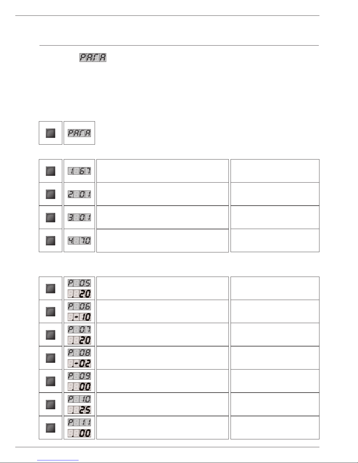
SETTING THE PARAMETERS
Parameter mode
To access Parameter mode when the system is in Pilot mode, press MODE once.
To scroll through the list of parameters, simply press “step”.To modify a parameter value, use the + or - keys.
Then press “Store” to save the value you just changed.The screen flashes once to confirm the data has been saved.
To activate the parameters you changed, press “Mode” once more (which brings you into Info mode). However, if you do not press a key, the
system returns to Pilot mode after 20 minutes and automatically enables the changes.
MODE
Adjusting the hot water temperature
STEP
STEP
STEP
STEP
Minimum central heating temperature when using an outdoor sensor
STEP
Minimum outdoor temperature
(adjust the heating curve)
STEP
Maximum outdoor temperature
(adjust the heating curve)
STEP
Frost protection temperature
STEP
Correction based on the outdoor temperature
STEP
Blockage T 0 = Disabled
90
01
01
90
60
0
20
- 15
00
00
STEP
Key Display Description of parameters Factory setting
Key Screen Description of parameters Factory setting
Key Display
Parameters for the specialist: only accessible by using the Code
Booster 00 = Stop (minute)
STEP
00
Production
of hot water
00 = Stop
01 = Start
02 = Stop + pump continuously on
03 = Start + pump continuously on
Turn on/Turn off
the heating
00 = Stop
01 = Start
02 = Stop + pump continuously on
03 = Start + pump continuously on
Maximum temperature in Central Heating mode
Page 3

18
MCBA FOR SPECIALISTS:
INSTALLER, SERVICE ENGINEER
Night-time heating temperature reduction (°C)
STEP
Fan speed in heating mode (rpm x 100)
STEP
10
52
Key Display Description of the parameters Factory setting
Max. fan speed in heating mode (rpm x 100)
STEP
00
Max fan speed in hot water mode (rpm x 100)
STEP
57
Max. fan speed in hot water mode (rpm x 100)
STEP
00
Min. fan speed (rpm x 100)
STEP
15
Min. fan speed (rpm x 100)
STEP
00
Fan speed at ignition (rpm x 100)
STEP
37
Heating pump time delay 0 = 10 sec (minute) 00
STEP
Hot water pump time delay 10.2 = 10 sec (minute) 16
00
01
01
03
STEP
Burner interlock hysteresis (heating)
STEP
Burner trigger hysteresis (heating)
STEP
Burner interlock hysteresis (hot water)
STEP
Burner trigger hysteresis (hot water)
STEP
04Hot water mode interlock hysteresis
STEP
Hot water mode trigger hysteresis
STEP
01
Page 4

19
MCBA FOR SPECIALISTS:
INSTALLER, SERVICE ENGINEER
Heating lock time (sec x 10.2)
STEP
Hot water lock time (sec x 10.2)
STEP
Lock time to switch from hot water mode to heating mode
(sec x 10.2)
STEP
Difference T1 - T2 for modulation
STEP
BUS address (-1 = disabled)
STEP
Increase the primary temperature value to generate hot
water (relative to the hot water temperature)
STEP
1st digit: heating circuit (AM3-11 – 4-way valve)
0 = disabled 5 = enabled
2nd digit: the demand for heat comes from:
0 = room thermostat
STEP
00
00
00
05
- 01
05
00
Key Display Description of the parameters Factory setting
1st digit: Hot water circulator pump (= 1)
2nd digit: tank with NTC3 sensor (= 2)
STEP
Manual fan speed (- 01 = modulation)
12
- 01
11
00
60
30
01
00
STEP
1st digit: PWM pump operating speed
2nd digit: PWM pump speed during time-delay
STEP
Holding temperature
STEP
Maximum temperature for the heating circuit outlet
(AM3-11 – 4-way valve)
STEP
Minimum temperature for the heating circuit outlet
(AM3-11 – 4-way valve)
STEP
Hysteresis of the heating circuit outlet temperature
(AM3-11 – 4-way valve)
STEP
1st digit: Special pump (0 = disabled)
2nd digit: Minimum disable cycle (0 = disabled)
STEP
Page 5

20
MCBA FOR SPECIALISTS:
INSTALLER, SERVICE ENGINEER
INFORMATION ON THE INSTALLATION
Info mode
To switch from Pilot mode to Info mode, press “Mode” twice.
ENTERING THE CODE
Code mode
You can access the following parameters by entering the service
code:
• Parameters 5 - 42
• Communication mode
• Fan Speed mode
• ERROR mode
MODE
MODE
Start temperature T1 in °C
STEP
Return temperature T2 in °C
STEP
Hot water temperature T3 in °C
STEP
Outdoor temperature T4 in °C
STEP
Not used
STEP
Start temperature calculated in °C
STEP
Rate of increase in the start
temperature in °C/s
STEP
Rate of increase in the return
temperature in °C/s
STEP
Rate of increase in the hot water
temperature in °C/s
STEP
Heating circuit outlet temperature
(AM3-11 – 4-way valve)
STEP
Press “STEP” until the system displays the information you need.
The point located behind the first position flashes to indicate that
the boiler is in “INFO” mode.
Key Display Description of parameters
Key Display
STEP
STORE
MODE STEP
+
or
-
Press “STEP” once and the system displays “C”
in position 1, followed by arbitrary
characters in positions 3 and 4.
Press “STORE”, the screen flashes
briefly to indicate that the code has been accepted.
Press “MODE” until
the system displays the correct mode.
Press “+” or “-” to change the code.
Only ACX authorised installers know the access code.
For further information, please contact our after-sales
department.
To access Code mode, press
MODE and STEP simultaneously
(only from Pilot mode!).
Page 6

21
MCBA FOR SPECIALISTS:
INSTALLER, SERVICE ENGINEER
COMMUNICATION MODE (WITH CODE)
When in this mode, the system displays the communication between
the boiler and the control module, the optional interface kit or the
optional programmable room thermostat.
FAN MODE (WITH CODE)
ERROR MODE (WITH CODE)
“ERROR” mode indicates the most recent error, as well as the
status of the boiler and its readings at the time this error occurred.
Fan speed
MODE
The current fan speed is 5,500 rpm.
STEP
Key Display Description of parameters
MODE
Code mode
(See the table on page 16 for a full list)
STEP
Status of the boiler at the time of the
error (See the table on page 16)
STEP
Start temperature T1 at the time of
the error
MODE
Return temperature T2 at the time of
the error
STEP
Hot water temperature T3 at the time
of the error
STEP
Outdoor temperature T4 at the time of
the error
STEP
Key Display
Key Display Description of parameters
MODE
No communication
Communication between the boiler
module and the optional control
modules only (RMCI)
STEP
Communication between all the
devices connected
Key Display
Key Display Description of parameters
Temp. °C R Ω Temp. °C R Ω
-20 98200 40 6650
-15 75900 45 5520
-10 58800 50 4610
-5 45900 55 3860
0 36100 60 3250
5 28600 65 2750
10 22800 70 2340
15 18300 75 1940
20 14700 80 1710
25 12000 85 1470
30 9800 90 1260
35 8050 95 1100
100 950
Temperature sensor resistance tables
Page 7

22
SPARE PARTS
No. Jackets Codes HeatMaster®201
A01 Right side 21471415
A02 Left side 21471415
A03 Right side rear corner 21478415
A04 Left side rear corner 21473415
A05 Rear panel 21474415
A06 Right side front corner 21472415
A07 Left front side 21479415
A08 Upper front panel 2147A415
A09 Lower front panel 2147B415
A10 Burner cover 21476415
A11 Rear top cover 21475415
A12 Front top cover 21475416
A13 Rear half-base 2147S415
A14 Unequipped control panel 21477416
A15 Body + accessories (package No. 1) 27300047
No. Accessories
B01 Low-water-level pressure switch 557D3011
B02 Wilo circulator pump 557A4007
B03 3 bar / Ø 3/4” - 1” safety valve 557A1048
B04 Burner chamber insulating cover 51700041
B05 8-l expansion vessel 55301200
B06 Steam trap, Ø 1/2” 557A3001
B07 Drain cock, Ø 3/4” 557A1000
B08 Fill set, Ø 1/2” 55426018
B09 Type A, high-level turbulators 507F2009
B10 Type B, low-level turbulators 507F2010
No. Setting and electrical accessories
C01 MCBA 537D8016
C02 Transformer 547D3021
C03 NTC Duplo (NTC1 - NTC2) 5476G002
C04 NTC Single (NTC3) 5476G003
C05 Module AM3-11 10800080
C06 Module AM3-2 10800060
C07 Full control panel 24614133
C08 Display 537D3020
C09 Display case 537D3023
C10 Pressure gauge-thermometer 54441008
C11 ON/OFF switch 54766016
C12 Summer/Winter switch 54766017
C13 Control panel self-adhesive 617G0105
No. Burner
D01 Full burner 237D0118
D02 Fan 537D3034
D03 Venturi 537D4042
D04 110 x 3.5mm O-ring 557A0045
D05 Plate fan seal 557A0040
D06 Burner chamber plate seal 557A0020
D07 Ø 98mm burner tube + NIT 537DZ019
D08 Chamber plate sealing cord 51700025
D09 Ignition electrode 537DZ020
D10 Ignition cable 25760046
D11 Burner chamber plate insulating stone 51700040
D12 Burner chamber plate 2147P416
D13 Gas valve 537D4041
D14 Valve flange 537D8021
Page 8

23
SERVICE RECORD
Service date:
% CO2 (min. load):
% CO2 (max. load):
Gas
Propane
Model:
Serial number:
Heating system pressure setting:
❏
❏
Name and signature:
Flue gas T°:
Efficiency:
Gas pressure:
INSTALLATION DETAILS
Service date:
% CO2 (min. load):
% CO2 (max. load):
Gas
Propane
Comments:
❏
❏
Name and signature:
Flue gas T°:
Efficiency:
Gas pressure:
SERVICE NOTES
Service date:
% CO2 (min. load):
% CO2 (max. load):
Gas
Propane
Comments:
❏
❏
Name and signature:
Flue gas T°:
Efficiency:
Gas pressure:
Service date:
% CO2 (min. load):
% CO2 (max. load):
Gas
Propane
Comments:
❏
❏
Name and signature:
Flue gas T°:
Efficiency:
Gas pressure:
Service date:
% CO2 (min. load):
% CO2 (max. load):
Gas
Propane
Comments:
❏
❏
Name and signature:
Flue gas T°:
Efficiency:
Gas pressure:
Service date:
% CO2 (min. load):
% CO2 (max. load):
Gas
Propane
Comments:
❏
❏
Name and signature:
Flue gas T°:
Efficiency:
Gas pressure:
Page 9

24
SERVICE RECORD
Service date:
% CO2 (min. load):
% CO2 (max. load):
Gas
Propane
Comments:
❏
❏
Name and signature:
Flue gas T°:
Efficiency:
Gas pressure:
Service date:
% CO2 (min. load):
% CO2 (max. load):
Gas
Propane
Comments:
❏
❏
Name and signature:
Flue gas T°:
Efficiency:
Gas pressure:
Service date:
% CO2 (min. load):
% CO2 (max. load):
Gas
Propane
Comments:
❏
❏
Name and signature:
Flue gas T°:
Efficiency:
Gas pressure:
Service date:
% CO2 (min. load):
% CO2 (max. load):
Gas
Propane
Comments:
❏
❏
Name and signature:
Flue gas T°:
Efficiency:
Gas pressure:
Service date:
% CO2 (min. load):
% CO2 (max. load):
Gas
Propane
Comments:
❏
❏
Name and signature:
Flue gas T°:
Efficiency:
Gas pressure:
Service date:
% CO2 (min. load):
% CO2 (max. load):
Gas
Propane
Comments:
❏
❏
Name and signature:
Flue gas T°:
Efficiency:
Gas pressure:
Page 10

Page 11

INTERNATIONAL
ACV international n.v
KERKPLEIN, 39
B-1601 RUISBROEK - BELGIUM
TEL.: +32 2 334 82 20
FAX: +32 2 378 16 49
E-MAIL: international.info@acv-world.com
BELGIUM
ACV BELGIUM nv/sa
KERKPLEIN, 39
B-1601 RUISBROEK-BELGIUM
TEL.: +32 2 334 82 40
FAX: +32 2 334 82 59
E-MAIL: belgium.info@acv-world.com
CHILE
ALBIN TROTTER Y ACV LTDA
SAN PABLO 3800
QUINTA NORMAL - SANTIAGO - CHILE
TEL.:+56 2 772 01 69
FAX:+56 2 772 92 62/63
E-MAIL: chile.info@acv-world.com
CZECH REPUBLIC
ACV CR SPOL. s.r.o
NA KRECKU 365
CR-109 04 PRAHA 10 - CZECH REPUBLIC
TEL.:+420 2 720 83 341
FAX:+420 2 720 83 343
E-MAIL: ceskarepublika.info@acv-world.com
DEUTSCHLAND
ACV WÄRMETECHNIK GMBH & CO KG
GEWERBEGEBIET GARTENSTRASSE
D-08132 MÜLSEN OT ST. JACOB - DEUTSCHLAND
TEL.:+49 37601 311 30
FAX:+49 37601 311 31
E-MAIL: deutschland.info@acv-world.com
ESPAÑA
ACV ESPAÑA
C/DE LA TEIXIDORA, 76
POL. IND. LES HORTES
E-08302 MATARÓ - ESPANA
TEL.:+34 93 759 54 51
FAX:+34 93 759 34 98
E-MAIL: spain.info@acv-world.com
FRANCE
ACV FRANCE sa
31, RUE AMPERE - Z.I MI - PLAINE
F-69680 CHASSIEU - FRANCE
TEL.:+33 4 72 47 07 76
FAX:+33 4 72 47 08 72
E-MAIL: france.info@acv-world.com
ITALIA
ACV ITALIA
VIA PANA 92
I-48018 FAENZA (RA) - ITALIA
TEL.:+39 0546 64 61 44
FAX:+39 0546 64 61 50
E-MAIL: italia.info@acv-world.com
NEDERLAND
ACV NEDERLAND bv
POSTBUS 350
NL-2980 AJ RIDDERKERK - NEDERLAND
TEL.:+31 180 42 10 55
FAX:+31 180 41 58 02
E-MAIL: nederland.info@acv-world.com
POLAND
ACV POLSKA sp. z.o.o.
UL.WITOSA 3
87 - 800 WWOCWAWEK - POLAND
TEL.:+48 54 412 56 00
FAX:+48 54 412 56 01
E-MAIL: polska.info@acv-world.com
PORTUGAL
BOILERNOX LDA
RUA OUTEIRO DO POMAR
CASAL DO CEGO, FRACÇÃO C,
PAVILHÃO 3 - MARRAZES
2400-402 LEIRIA - PORTUGAL
TEL.:+351 244 837 239/40
FAX:+351 244 823 758
E-MAIL: boilernox@mail.telepac.pt
RUSSIA
ACV RUSSIA
1/9, MALYI KISELNYI
103031 MOSCOW - RUSSIA
TEL.:+7 095 928 48 02 / +7 095 921 89 79
FAX:+7 095 928 08 77
E-MAIL: russia.info@acv-world.com
SLOVAK REPUBLIC
ACV SLOVAKIA s.r.o.
PLUHOVÁ 49
831 04 BRATISLAVA - SLOVAK REPUBLIC
TEL.:+421 2 444 62 276
FAX:+421 2 444 62 275
E-MAIL: slovakia.info@acv-world.com
SLOVENIA
ACV D.O.O. SLOVENIA
OPEKARNA 22b
1420 TRBOVLJE - SLOVENIA
TEL.:+386 356 32 830
FAX:+ 386 356 32 831
E-MAIL: slovenia.info@acv-world.com
UK
ACV UK Ltd
ST.DAVID’S BUSINESS PARK
DALGETY BAY - FIFE - KY11 9PF
TEL.:+44 1383 82 01 00
FAX:+44 1383 82 01 80
E-MAIL: uk.info@acv-world.com
USA
TRIANGLE TUBE PHASE III
FREEWAY CENTER - 1 TRIANGLE LANE
BLACKWOOD NJ 08012 - USA
TEL.:+1 856 228 8881
FAX:+1 856 228 3584
E-MAIL: sales@triangletube.com
excellence in hot water
www.acv-world.com
ARGENTINA
TECNOPRACTICA
ALFEREZ BOUCHARD 4857
1605 CARAPACHAY - BUENOS AIRES
TEL.: +54 11 47 65 33 35
FAX: +54 11 47 65 43 07
E-MAIL: jchas@tecnopractica.com
AUSTRALIA
HUNT HEATING PTY LTD
10 GARDEN BOULEVARD
3172 VICTORIA - AUSTRALIA
TEL.: +61 3 9558 7077
FAX: +61 3 9558 7027
E-MAIL: enquiries@huntheat.com.au
BRAZIL
SIMETAL INDUSTRIA E COMERCIO
DE FERRAMENTAS LTDA
RUA GERSON ANDREIS 535
95112 - 130 CAXIAS DO SUL - BRAZIL
TEL.: +55 54 227 12 44
FAX: +55 54 227 12 26
E-MAIL: export@simetall.com.br
BULGARIA
PROXIMUS ENGINEERING LTD
7 BIAL KREM STR.
9010 VARNA - BULGARIA
TEL.:+359 52 500 070
FAX:+359 52 301 131
E-MAIL: info@proximus-bg.com
CHINA
BEIJING HUADIAN HT POWER TECHNOLOGY
DEVELOPMENT CO. LTD
ROOM B-912, TOWER B, COFCO PLAZA
N°. 8, JIANGUOMENNEI AVENUE
BEIJING 100005 - PEOPLE’S REPUBLIC OF CHINA
TEL.:+86 10 652 30 363/393 EXT 101
FAX:+86 10 652 27 071
E-MAIL: li.zheng@acv-world.com
SHANGHAI COOLTECH LTD
14/F E. CHINA MERCHANTS PLAZA
N°. 333 CHENGDU ROAD (N)
200041 SHANGHAI - CHINA
TEL.:+86 21 52 98 11 22 - 820
FAX:+86 21 52 98 13 58
E-MAIL: cooltech@cooltech.sh.cn
DENMARK
VARMEHUSET
FRICHSVEJ 40 A
8600 SILKEBORG - DENMARK
TEL.:+45 86 82 63 55
FAX:+45 86 82 65 03
E-MAIL: vh@varmehuset.dk
ESTONIA
TERMOX AS
TAHE 112A
51013 TARTU - ESTONIA
TEL.:+372 736 73 39
FAX:+372 736 73 44
E-MAIL: termox@termox.ee
GREECE
ESTIAS
MARASLI STREET 7
54248 THESSALONIKI - GREECE
TEL.:+30 23 10 31 98 77 / +30 23 10 32 03 58
FAX:+30 23 10 31 97 22
E-MAIL: info@genikithermanseon.gr
ÎLE MAURICE
SOTRATECH
29, RUE MELDRUM
BEAU BASSIN - ÎLE MAURICE
TEL.:+230 46 76 970
FAX:+230 46 76 971
E-MAIL: stech@intnet.mu
LITHUANIA
UAB “GILIUS IR KO”
SAVARNORIU PR. 192
3000 KAUNAS - LITHUANIA
TEL.:+370 37 308 930
FAX:+370 37 308 932
MAROC
CASATHERM
PLACE EL YASSIR
20300 CASABLANCA - MAROC
TEL.:+212 22 40 15 23
FAX:+212 22 24 04 86
MOLDAVIA
STIMEX - PRIM S.R.L.
STR BUCURESTI, 60A
2012 CHISINAU - MOLDAVIA
TEL.:+37 32 22 46 75
FAX:+37 32 27 24 56
E-MAIL: stimex@slavik.mldnet.com
NEW ZEALAND
ENERGY PRODUCTS INTERNATIONAL
8/10 BELFAST PLACE
PO BOX 15058 HAMILTON - NEW ZEALAND
TEL.:+64 7 847 27 05
FAX:+64 7 847 42 22
E-MAIL: pmckenzie@tycoint.com
ÖSTERREICH
PROTHERM HEIZUNGSTECHNIK Gmbh
TRAUNUFERSTRASSE 113
4052 ANSFELDEN - ÖSTERREICH
TEL.:+43 7229 804 82
FAX:+43 7229 804 92
E-MAIL: protherm@nextra.at
ROMANIA
SC TRUST EURO THERM SA
D.N PIATRA NEAMT - ROMAN
km 2 C.P 5 O.P 3 jud. Neamt
5600 PIATRA NEAMT - ROMANIA
TEL.:+40 233 20 62 06
FAX:+40 233 20 62 00
E-MAIL: office@eurotherm.ro
TUNISIE
SO.CO.ME CHAUMAX
BOÎTE POSTALE N°44
1002 TUNIS - TUNISIE
TEL.:+216 71 78 15 91
FAX:+216 71 78 87 31
UKRAINE
UKRTEPLOSERVICE LTD
PR. LAGUTENKO 14
83086 DONETSK - UKRAINE
TEL.:+38 062 382 60 47/48
FAX:+38 062 335 16 89
 Loading...