

ACV HeatMaster71, HeatMaster101, HeatMaster201 INSTALLATION OPERATING AND SERVICING INSTRUCTIONS
Page 1

®
HeatMaster
Installation, operating and
servicing instructions
ENGLISHFRANCAISNEDERLANDSESPAÑOLITALIANODEUTSCH
HeatMaster
HeatMaster
HeatMaster
®
71
®
101
®
201
664Y2500.B
EN • 1
Page 2

INDEX
IMPORTANT NOTES 3
Who should read these instructions 3
Symbols 3
ENGLISHFRANCAISNEDERLANDSESPAÑOLITALIANODEUTSCH
Recommendations 3
Certification 3
Important notes 3
DESCRIPTION 4
Working principle 4
Temperature control 4
Building characteristics 4
Frost protection 4
Packaging 4
USER GUIDE 6
Use of the boiler 6
Setting the parameters 7
TECHNICAL CHARACTERISTICS 8
General characteristics 8
Water quality 8
Gas category 9
Domestic hot water performance 9
ELECTRICAL CONNECTION 10
Electrical supply 10
Alarm module 10
HeatMaster® 71-101wiring diagram 12
HeatMaster® 201 wiring diagram 13
INSTALLATION 14
Dimensions 14
Boiler Room 15
Chimney connection 16
Domestic hot water connection 18
Heating connection 19
Gas connection 19
BURNER CHARACTERISTICS 20
ACV BG 2000-M air/gas pre-mix burners 20
INSTALLATION AND COMMISSIONING 22
Filling of domestic hot water and heating circuits 22
MAINTENANCE 23
Annual maintenance 23
Boiler maintenance 23
Maintenance of safety devices 23
Burner maintenance 23
Draining of the boiler 23
MCBA PARAMETERS FOR THE SPECIALIST 24
Standby Mode 24
Setting the parameters 25
System information 26
Entry of the maintenance code 26
Setting the parameters: only accessible using the code 27
Communication mode 30
Error Mode 30
List of error codes + solutions 31
PARTS LIST at the end of the instructions
664Y2500.B
EN • 2
Page 3

IMPORTANT NOTES
WHO SHOULD READ THESE INSTRUCTIONS
These instructions should be read by:
- the design engineer/consultant
- the user
- the installer
- the service engineer
SYMBOLS
The following symbols are used in this manual:
Essential instruction for the correct
operation of the installation.
Essential instruction for the safety
of persons and the environment.
Electrocution hazard: use a qualified
technician.
• Defective parts can only be replaced with original factory
parts. You will find a list of spare parts and their ACV
reference number at the end of this manual.
• The burners are pre-adjusted in the factory for natural gas
[equivalent to G20].
• Specific regulation in Belgium:
The CO2, gas flow, air flow and air/gas supply parameters
are adjusted in the factory and cannot be changed in Belgium,
except for type 1 2E(R)B boilers.
• Before carrying out any work on the boiler, it is important to
isolate the electrical supply to the unit.
• The user must not attempt to gain access to the components
inside the boiler or the control panel.
CERTIFICATION
The appliances bear the “CE” mark, in accordance with the
standards in force in the various countries [European Directives
92/42/EEC “Efficiency”, 90/396/CEE “Gas Appliances”].
These appliances also bear the Belgian gas boiler quality label
“HR+”[gas boiler].
ENGLISHFRANCAISNEDERLANDSESPAÑOLITALIANODEUTSCH
Burn hazard.
RECOMMENDATIONS
• Before installing and bringing the boiler into service, first
carefully read this manual.
• It is prohibited to modify the interior of the appliance in any
way, without the manufacturer’s prior written agreement.
• The boiler must be installed by a qualified engineer, in
accordance with applicable local standards and local codes
in force.
• Failure to follow the instructions describing test operations
and procedures could result in personal injury or a risk of
environmental pollution.
• In order to ensure the appliance operates safely and
correctly, it is important to have it serviced by an approved
contractor.
• If there is a problem please contact your contractor for
advice.
• In spite of the strict quality standards that ACV applies to
its appliances during production, inspection and transport,
faults may occur. Please immediately notify your approved
contractor of any faults. Remember to indicate the fault
code as it appears on the screen.
IMPORTANT NOTES
IF YOU SMELL GAS:
- Isolate the gas supply immediately.
- Ventilate the room (Open the windows).
- Do not use electrical appliances and do not operate switches.
- Notify your gas supplier and/or your installer immediately.
This manual forms part of the items delivered with the appliance
and must be given to the user to keep in a safe place!
The system must be installed, commissioned, serviced and
repaired by an approved installer, in accordance with current
standards in force.
The manufacturer declines all liability for any damage caused
as a result of incorrect installation or in the event of the use
of appliances or accessories that are not specified by the
manufacturer.
The manufacturer reserves the right to change the
technical characteristics and features of its products
without prior notice.
The availability of certain models as well as their
accessories may vary according to markets.
664Y2500.B
EN • 3
Page 4

DESCRIPTION
WORKING PRINCIPLE
The HeatMaster® is a high performance hot water producer
ENGLISHFRANCAISNEDERLANDSESPAÑOLITALIANODEUTSCH
using indirect heat transfer due to it’s Tank-in-Tank technology.
At the centre of the HeatMaster® there is a stainless steel
cylinder through which the flue tubes pass. It is surrounded by
a mild steel shell containing the primary water (neutral fluid).
The outer shell extends down to the combustion chamber and
also surrounds the flue gas tubes. The heat exchange surface
is therefore larger than that of traditional direct fired hot water
boilers.
A circulating pump installed on the primary circuit moves the
water around the tank, heating rapidly and maintaining it at a
constant temperature across the primary circuit.
The burner heats the primary fluid which indirectly heats
the stainless steel cylinder containing the hot water. As with
all Tank-in-Tank systems, the cylinder is corrugated over its full
height and suspended in the HeatMaster® by its hot and cold
water connections.
The fact that the cylinder expands and contracts during use
and that the cold water is not in contact with the intense heat
from the burner flame means that the build-up of lime scale is
prevented.
This resistance to lime scale, along with the corrosion resistance
of the stainless steel, eliminates the need for sacrificial anodes.
The HeatMaster® has a major advantage over other hot water
boilers: it heats hot water with a primary circuit, which allows the
primary fluid to also be used for heating.
The connection of two, three, four or more HeatMaster® in a
cascade meets the most demanding requirements in hot water
and in heating.
Indeed, if it is used in combination with Smart, HR and Jumbo
cylinders, the HeatMaster® can respond to the most demanding
hot water requirements.
TEMPERATURE CONTROL
The HeatMaster® 201 are equipped with an electronic
controller MCBA [MicroproCessor Burner Automate], which
handles both the safety functions (ignition, flame monitoring
temperature limitation, etc,…) and the temperature control of
the boiler. This MCBA can also operate as a regulator governed
by outdoor temperature when the outside temperature sensor
is fitted.
However, this regulator can also operate with a standard room
thermostat (on/off). Combining this regulator with a room
thermostat provides temperature control governed by outdoor
weather conditions, with indoor compensation.
The user may access four parameters to adjust all the necessary
settings. By entering a specific maintenance code into the unit,
qualified installers may access certain parameters, in order to
adapt the boiler to special requirements. In principle, these are
factory preset for all normal applications.
CONSTRUCTION FEATURES
Outer body
The outer body containing the primary fluid is constructed from
carbon steel (STW 22).
TANK-IN-TANK accumulator/heat exchanger
The internal large surface ring-shaped inner tank for the production
of hot water is constructed from Chrome/Nickel 18/10 stainless
steel. It is corrugated over its height by an exclusive manufacturing
process and is entirely argon arc welded using the TIG (Tungsten
Inert Gas) method.
Combustion gas circuit
The gas combustion circuit is protected by paint and includes:
• Flue tubes
The HeatMaster® include 8 tubes (HeatMaster® 71-101)
and 15 tubes (HeatMaster® 201) in steel with an internal
diameter of 64 mm. Each tube is equipped with a stainless
steel turbulator designed to improve thermal exchange and
reduce flue gas temperature.
• Combustion chamber
The combustion chamber of the HeatMaster® models is
entirely water cooled.
Insulation
The boiler body is fully insulated by rigid polyurethane foam
with a high coefficient thermal insulation, sprayed on without the
use CFC’s.
Casing
The boiler is covered with a steel jacket which has been de-greased
and phosphated before being stove enamelled at 220 °C.
Burner
The HeatMaster® 71 - 101 - 201 models are always supplied with
a low NOx air/gas pre-mix burner ACV BG 2000-M.
FROST PROTECTION
The boiler is equipped with an integrated frost protection: as
soon as the boiler temperature [NTC1 probe] drops below 7°C,
the central heating pump is activated. As soon as the NTC1
temperature is lower than 3°C, the burner ignites until the
temperature exceeds 10°C. The pump continues to turn for
approximately 10 minutes. If an outside temperature sensor
is connected, the pump is activated as soon as the external
temperature goes under the pre-defined threshold.
In order to enable the HeatMaster® boiler to protect the system
against freezing, all the valves of the radiators and the convectors
should be completely open.
PACKAGING
HeatMasters® 71 and 101 are supplied completely assembled
and ready for use.
The HeatMaster® 201 is supplied in four separate packages.
664Y2500.B
• Package N° 1: Foam insulated body + hydraulic accessories +
control board.
• Package N° 2: Flue reducer.
• Package N° 3: The jacket.
• Package N° 4: The burner and its cover, door insulation and
sealing cord.
EN • 4
Page 5

DESCRIPTION
HeatMaster® 71 / 101
1. Cold water inlet and filling loop connection
2. Au t o-air vent
3. Primary NTC 1 and 2 sensors
4. Primary expansion tank (2x)
5. Filling loop connection to primary circuit
6. Low- wate r p res sur e s w itch
7. Thermometer bulb and pressure gauge connection
8. Primary safety valve
9. Char ging pum p
10. Rigid polyurethane foam insulation
11. Chimney reduction with vertical outlet
12. Turbulators
13. Heating flow
14. Domestic hot water outlet
15. Internal stainless steel tank
16. Stainless steel dry-well with ECS NTC 3 sensor
17. Primary tank
18. Flue tubes
19. Heating return
20. Drain cock
21. Combustion chamber
1
11
ENGLISHFRANCAISNEDERLANDSESPAÑOLITALIANODEUTSCH
2
3
4
5
6
7
8
9
12
13
14
15
16
17
18
19
20
HeatMaster® 201
1. Chimney reduction with horizontal outlet
(vertical outlet optional)
2. Cold water inlet
3. Primary NTC 1 and 2 sensors
4. T&P valve connection (optional)
5. Au t o -air vent
6. Rigid polyurethane foam insulation
7. Internal stainless steel tank
8. Low - wat er pre ssure swi t ch
9. Pressure gauge connection
10. Thermostat control bulb
11. C h ar gi n g p u mp (2 x)
12. Stainless steel dry-well with ECS NTC 3 sensor
13. Domestic hot water outlet
14. Heating flow
15. Filling loop connection
16. Filling of primary circuit
17. Primary expansion vessel (4x)
18. Flue gas tubes and turbulators
19. Heating return
20. Drain cock
21. Primary safety valve
22. Primary circuit tank
23. Combustion chamber
10
10
11
21
1
12
2
3
4
5
6
13
14
15
16
17
7
18
8
19
9
20
21
22
23
664Y2500.B
EN • 5
Page 6

USER GUIDE
USE OF THE BOILER
ENGLISHFRANCAISNEDERLANDSESPAÑOLITALIANODEUTSCH
ACV recommends that the boiler is inspected and serviced, if required, at least once a year by a competent and qualified
engineer. More frequent servicing may be required depending on boiler use, if this is the case consult your installer for
advice.
Starting the burner:
In normal operation, the burner starts automatically as soon as the boiler drops below the temperature setpoint.
The user must not attempt to gain access to the components inside the control panel.
HeatMaster
1. Temp e r at u r e - p r e s sure g a u g e
2. Display - MCBA cont roller
3. General switch
4. Summer/winter switch
®
control panel
Heating circuit pressure
It may be necessary to add water to obtain the correct
pressure required in the heating system. This pressure
is displayed on the temperature-pressure gauge on the
boiler control panel.
The minimum cold fill pressure should be 1 bar. The
precise operational pressure will depend on the height
of the building (See Bringing Into Service section - Filling up of
DHW and heating circuits)
.
1 2 43
If the pressure falls to below 1 bar, the boiler low water
pressure switch will stop the boiler until the pressure is
re-established.
Safety valves
If water is discharged from one of the safet y valves, stop
the boiler and call an engineer.
664Y2500.B
EN • 6
Page 7

USER GUIDE
SETTING THE PARAMETERS
• Domestic hot water temperature instruction:
(Hot water temperature)
- Press the “mode” key once: the screen indicates “PARA”.
- Press the “step”key: the first digit is 1 and the last two digits
indicate the current hot water temperature setting.
- To change this temperature, press “+” or “-” keys until the
temperature indicated by the last t wo digits is the desired
temperature.
- Press “store” to save the setting.
- Press the “mode” key twice to return to normal operating
mode [Stand-by).
• Enabling and disabling hot water mode:
(Hot water)
- Press “mode” once: the screen displays “PARA”.
- Press the “step” button twice: the first digit is 2 and the las t
two digits indicate the current setting.
00 = disabled; 01 = enabled.
- To change this parameter, press the “+” or “-” keys until you
reach the desired value:
00 = disabled; 01 = enabled.
- Press “store” key to save the setting.
- Press the “mode” key twice to return to normal operating
mode [Stand-by).
ENGLISHFRANCAISNEDERLANDSESPAÑOLITALIANODEUTSCH
• Enabling and disabling central heating mode:
(Central heating)
- Press “mode” key once: the screen displays “PARA”.
- Press the “step” key three times: the first digit is 3 and the
last t wo digits indicate the current setting.
00 = disabled; 01 = enabled.
- To change this parameter, press the “+” or “-” keys until you
reach the desired value:
00 = disabled; 01 = enabled.
- Press “store” key to save the setting.
- Press the “mode” key twice to return to normal operating
mode [Stand-by).
• Setting the temperature of the central heating:
(the maximum temperature for the heating circuit)
- Press “mode” once: the screen displays “PARA”.
- Press the “step” key four times: the first digit is 4 and the last
two digits indicate the current temperature setting for the central heating.
- To change this t emperature, press the “+” or “-” keys until the
temperature indicated by the last t wo digits is the desired
temperature.
- Press “store” to save the setting.
- Press the “mode” key twice to return to normal operating
mode [Stand-by).
MCBA Display
Fault:
The temperature setting of the appliance and the safety functions of its various parts are constantly monitored by the MCBA
controller. If a fault occurs, the MCBA turns the unit off and indicates an error code: the display flashes and the first character
is an “E” followed by the fault code (see list of faults).
To reset the unit:
- Press the “reset” key on the display panel.
- If the fault code appears again, contact your contractor.
664Y2500.B
EN • 7
Page 8

TECHNICAL CHARACTERISTICS
ENGLISHFRANCAISNEDERLANDSESPAÑOLITALIANODEUTSCH
Central heating
Input power (Input)
Useful nominal power (output)
Maintenance loss of the nominal value at 60°C
Flue gas
Flue gas circuit loss
Net fl ue gas temperature
Mass fl ow rate of combustion products
CO
natural gas
2
Gas
Gas fl ow rate G20 - 20 mbar
Gas fl ow rate G25 - (25 mbar)
Gas fl ow rate G31 (30 / 37 / 50 mbar)
Gas connection [F]
Hydraulic parameters
Max operating temperature
Total capacity
Heating circuit capacity
DHW cylinder heat exchange surface
Max operating pressure of the heating circuit
Max operating pressure of the secondary circuit
Primary circuit pressure drop
Mbar
g/sec.
% CO
M
M
M
Bar
Bar
Mbar
kW
kW
3
3
3
m
HeatMaster® 71 HeatMaster® 101 HeatMaster® 201
20.0 - 69.9 25.0 - 107.0 60.0 - 220.0
18.4 - 63.0 23.0 - 96.8 56.4 - 200.2
%
°C
2
/h
/h
/h
Ø
°C
L
L
2
0.60 0.65 0.30
0.6 1.4 2.4
172 165 190
9.2 - 32.1 11.5 - 49.2 27,6 - 101,2
9.0 9,0 9.0
2.17 - 7.40 2.64 - 11.32 6.35 - 25.40
2.46 - 8.60 3.08 - 13.17 7.38 - 29.54
0.82 - 2.86 0.94 - 4.50 2.45 - 9.81
3/4” 1” 1”1/4
95 95 95
239 330 641
108 130 241
3.14 3.95 5.30
333
10 10 10
46 83 240
Electrical connection
V/Hz
IP
W
30 30 30
230 / 50 230 / 50 230 / 50
180 200 800
Class
Supply voltage
Maximum electrical consumption.
Drained weight Kg 282 320 550
WATER QUALITY
• Chlorides: < 150 mg/l (304)
< 2000 mg/l (Duplex)
• 6 ≤ ph ≤ 8
664Y2500.B
EN • 8
Page 9

GAS CATEGORY
TECHNICAL CHARACTERISTICS
ENGLISHFRANCAISNEDERLANDSESPAÑOLITALIANODEUTSCH
Natural gas categories
I 2E(S)B *
I 2E(R)B **
I 2Er
I 2L
I 2E
I 2ELL
I 2H
I 2HS
(*) HeatMaster® 71 - (**) HeatMaster ® 101 - 201
[G20] 20 mbar - [G25] 25 mbar
[G20] 20 mbar - [G25] 25 mbar
[G20] 20 mbar - [G25] 25 mbar
[G25] 25 mbar
[G20] 20 mbar
[G20] 20 mbar - [G25] 20 mbar
[G20] 20 mbar
[G20] 25 mbar
Propane gas categories
I 3P
I 3P
I 3P
I 3+ ***
I 3B/P ***
I 3B/P ***
(***) HeatMaster ® 201
[G31] 30 mbar
[G31] 37 mbar
[G31] 50 mbar
[G30 + G31] 28 / 30 / 37 mbar
[G30] 28 / 30 mbar
[G30] 50 mbar
BE FR NL LU DE
DK - NL
NO - IT
BE - CH - ES
FR - UK - IE
PT - FI - SE
IT - GR
AT - CH
CZ - ES
NL - DE
LU - HU
AT - CH - CZ - DK - ES - IT -
FI - UK - IE - PT - SE - GR
BE - CH
ES - FR
UK - IE
IT - PT
CZ - DK - ES
FI - FR - UK
IE - IT - NL
NO - PT - SE
HU
AT - CH
CZ - DE
FR
DOMESTIC HOT WATER PERFORMANCE
System operating at 80°C
Peak fl ow rate at 40°C [ΔT = 30°C]
Peak fl ow rate at 45°C [ΔT = 35°C]
Peak fl ow rate at 60°C [ΔT = 50°C]
Peak fl ow rate at 70°C [ΔT = 60°C]
Peak fl ow rate at 80°C [ΔT = 70°C]
Peak fl ow rate at 40°C [ΔT = 30°C]
Peak fl ow rate at 45°C [ΔT = 35°C]
Peak fl ow rate at 60°C [ΔT = 50°C]
Peak fl ow rate at 70°C [ΔT = 60°C]
Peak fl ow rate at 80°C [ΔT = 70°C]
Continuous fl ow rate at 40°C [ΔT = 30°C]
Continuous fl ow rate at 45°C [ΔT = 35°C]
Continuous fl ow rate at 60°C [ΔT = 50°C]
Continuous fl ow rate at 70°C [ΔT = 60°C]
Continuous fl ow rate at 80°C [ΔT = 70°C]
L/10’
L/10’
L/10’
L/10’
L/10’
L/60’
L/60’
L/60’
L/60’
L/60’
L/h
L/h
L/h
L/h
L/h
HeatMaster® 71 HeatMaster® 101 HeatMaster® 201
646 905 1745
543 777 1489
346 514 971
268 385 763
203 290 586
2133 3172 6690
1794 2680 5667
1219 1813 3534
971 1378 2554
710 1003 1723
1835 2776 6117
1573 2379 5039
1101 1665 2914
918 1241 2128
675 903 1468
Reheat time at 60°C
664Y2500.B
Minutes
23 22 23
EN • 9
Page 10

ELECTRICAL CONNECTION
Electrical supply
The boiler uses a single phase supply at 230V - 50 Hz. A double
ENGLISHFRANCAISNEDERLANDSESPAÑOLITALIANODEUTSCH
pole isolator with a 6 Amp fuse or a 6 Amp MCB must be
fitted outside the boiler to allow the power to be shut off during
servicing and before any repairs are carried out.
Compliance
The installation must comply with current technical standards and
legislation in force.
Safety
The stainless steel cylinder must be connected separately to
earth.
The power to the boiler must be isolated before any
work is carried out on it.
Internal MCBA connections
X1: MCBA 230 V connection
X2: 24 V connector
X3: NTC connector
X4: NTC 6
X5: Communication
X7: Display connection
X8: Flat cable connection for alarm module AM3-2 and / or AM3-11
heating circuit control module
Alarm module
• Connect the alarm module ribbon cable “X7” to the MCBA
connector “X8”.
The volt free relays on the alarm module are activated as
described below.
1 - Alarm:
This contact closes if the MCBA is in safety shutdown position.
2 - External / burner gas valve - indication of function:
This contact closes if there is a heating request and the burner
is operating.
• Technical data:
- Ambient temperature: 0…60 °C
- Contact values: I
230 V (+10% / 15%) 50 Hz
If the inductor loads are connected it is necessary to
protect them against peak voltages (e.g. RC network).
RMS
1A
1 2
Alarm module (AM3-2)
The AM3-2 and AM3-11 alarm modules are only an option
for the HeatMaster® 71 / 101models.
Connection
for transformer
X1 X2 X5X4X3
X8
664Y2500.B
X7
MCBA
EN • 10
Page 11

ELECTRICAL CONNECTION
Second circuit module
(AM3-11)
Alarm module kit (optional)
1 2 3
1 - Heating pump switch:
This switch closes when there is a heating request.
2 - Four way valve closing switch (Three ways):
This switch closes if the MCBA regulator has to close the four
(3) way valve in accordance with the heating circuit start set
point.
3 - Four way (3 way) valve opening switch:
This switch closes if the MCBA regulator has to open the four (3)
way valve in accordance with the heating circuit start set point.
From delivery the heating circuit controlled by Module
AM3-11 is de-activated; to bring into service
parameter 34 needs to be modified (50 in place of
00) see pages 20 to 22.
ATTENTION: This parameter can only be changed by
approved ACV contractors.
Codes
AM3-2 : 10800094
ENGLISHFRANCAISNEDERLANDSESPAÑOLITALIANODEUTSCH
HeatMaster® 71 / 101 Panel
AM3-11 : 10800095
1. Alarm module flat cable connection
(option)
2. AM3-2 module (option)
3. AM3-11module (option)
664Y2500.B
1
2 3
EN • 11
Page 12

5
ELECTRICAL CONNECTION
WIRING DIAGRAM: Heatmaster® 71 / 101
ENGLISHFRANCAISNEDERLANDSESPAÑOLITALIANODEUTSCH
1. 230 Volt supply
2. 230 Volt outlet for AM3-11module (optional)
3. Charging pump
4. Heating pump
5. General switch
6. 230 Volt - 24 Volt transformer
7. MCBA controller
8. MCBA Display
9. Ignition and ionisation cable
10. SUMMER/winter switch
1 2 3 4
11. 7 pin burner plug
12. 4 pin burner plug
13. Room thermostat (optional)
14. Low water pressure safety switch
15. Primary NTC1 temperature sensor
16. Primary NTC2 temperature sensor
17. NTC3 hot water temperature sensor
18. NTC4 external temperature sensor (optional)
19. NTC6 2nd heating circuit temperature sensor (optional)
20. Zero volt of 24V circuit
B. Blue
Bk. Black
Br. Brown
G. Grey
Gr. Green
Or. Orange
Pk. Pink
R. Red
V. Violet
W. White
Y. Yellow
Y/Gr. Yellow/Green
Br
1 3 2
1 3 2
6
8
9
Y/Gr
M M
BBrY/GrBBr
Y/GrBBr
Y/GrBBr
4 6 5
7 9 8
4 6 5
7 9 8
B
B
Br
Br
B
Bk
X10.3
X10.1
X10.6
X10.7
Y/Gr
Br
5
X1.1
X1.2
X1.3
X1.4
X1.5
X1.6
Y/Gr
10 12 11
X12.
10 12 11
Y/Gr
B
Br
B
B
G
Y/Gr
Br Br
BBBr
BB
G
BrR
Y/Gr
Gr
Bk
Y
G
B
Y/Gr
Br
Y/Gr
G
Bk
B
Br
Y/Gr
7
X2.12
X2.11
X2.10
Bk
X2.9
X7
X2.8
X2.7
X2.6
X2.5
X2.4
X2.3
X2.2
X2.1
X3.6
X3.5
X3.4
X3.3
X3.2
X3.1
X4.3
X4.2
X4.1
X5.4
X5.3
X5.2
X5.1
B
Br
Bk
G
V
G
R
Gr
Bk
Y
G
B
Bk Br
Or
Br
R
Bk
Br
B
Bk
Or
V
G
Y/Gr
V
Bk
Bk
G
Y/Gr
R
Br
Or
B
10
Bk Y
BBBk
Or
Bk
Br
B
G
V
R
X11.
1 2 3 4 5 6 7 8 9 10 11 12
13
14
15
16
17
18 19
11
12
T8 T6 T7 B5 B4 T2 S3 T1 N L1
1 2 3 4 5 6 7 8 9 10 11 12 19
Br
Br
Br
B
Y/Gr
G
Gr
G
Br
Br
13
14
15
16
17
BUS B
18
BUS A
13
t
14
P
1
16
17
18
19
20
664Y2500.B
EN • 12
Page 13

ELECTRICAL CONNECTION
WIRING DIAGRAM: Heatmaster® 201
1. General switch
2. Module AM3-11:
3. Module AM3-2:
4. MCBA controller
5. 24 Volt Transformer
6. MCBA Display
7. Room thermostat (optional)
8. Low water pressure safety switch
9. NTC1 primary temperature sensor
10. NTC2 primary temperature sensor
11. NTC3 hot water temperature sensor
12. NTC4 outside temperature sensor (optional)
13. Summer/winter switch
14. NTC6 heating circuit start sensor (optional)
15. Heating circulator (not supplied)
16. Heating circulator (not supplied) if four way
valve motor driven on AM3-11
17. Charging pump
18. Charging pump
19. Booster circulating pump
20. Motor driven four way valve
21. Alarm switch
2
AM3 - 11
X1.1
X1.2
X2.1
X2.2
X3.1
X3.2
2
14 x 0,25mm
X7 X7
3
AM3 - 2
X1.1
X1.2
X2.1
X2.2
X3.1
X3.2
X3
7
t
01
02
03
04
G
V
X2.8
X2.10
X7
X1.3
X1.4
X1.1
X1.2
22. External gas valve switch/burner function
23. DHW mode function switch
24. Fan (BG 2000-M / 201)
25. Gas valve (BG 2000-M / 201)
26. Gas pressure switch (BG 2000-M / 201) (optional)
27. Charging pump control relay
9
12
8
10
P
11
06
05
07
08
09
10
11
13
Bk
B
Or
Br
R
X2.9
X3.1
X3.2
X3.3
X3.5
4
X10
MCBA
X1.5
X1.6
X2.4
14
BUS B
BUS A
O Volt
12
13
15
16
17
18
X2.11
19
G
Bk
V
X4.2
X5.1
X5.2
X2.5
X7
X2.6
X2.12
14
B
Br B W
Bk
Or
X5.4
X5.3
X4.3
X3.4
X2.1
X2.3
X2.2
2
14 x 0,25mm
6
2 x 2 fils
ENGLISHFRANCAISNEDERLANDSESPAÑOLITALIANODEUTSCH
5
B. Blue
Bk. Black
Br. Brown
G. Grey
Or. Orange
R. Red
V. Violet
W. White
Y/Gr. Yellow/Green
Bk
Br
B
R
V
Or
W G
B
B
Bk
Bk
V
W
R
Or
V
G
Bk
W
R
W
V
Bk
B B
1
Bk
X1
Br
B
01
02
03
L
N
X2
B
02
01
R
Bk
B
1
3
27
2
4
Or Or
B
V
B
G
B
10
07
05
04
03
06
R
B
R
M
M1 M M2 M M3 M M4
Y/Gr
15
16
11
08
09
B
R
B
Y/Gr
17
B
W
B
Bk
5
13
A1 A2
6
14
W
B
W
B
13
14
12
R
B
Y/Gr
Y/Gr
18
B
W
B
15
17
18
16
R
B
M
M5
Y/Gr
19
W
Bk
W
R
R
W W
B R R W Bk G V
21
20
22
19
Y/Gr
23
24
N
M
M6
20
Ph
N
Ph
21
Or
Or
V
G
Bk
B W V R Bk
Or
L1 N T1
X4
28
27
26
25
N
Ph
3 x 0,75
T2
S3
B4
4 x 0,75
23
N
22
2 1 3 2 1 5 4
3 2 1
BG 2000-M/201
24
5 4 3 2 1
X5
Br
Br
2 x 0,75
B5
B
G
Or
T6
T7
T8
B
P
25
26
664Y2500.B
EN • 13
Page 14

DIMENSIONS
ENGLISHFRANCAISNEDERLANDSESPAÑOLITALIANODEUTSCH
The boiler is delivered completely assembled, tested and packaged on a wood suppor t with anti-shock edges and protected
by a heat-shrunk plastic film.
On receipt and after having removed the packaging, check that the boiler is not damaged.
For transport, please refer to sizes and weights mentioned below.
AMm1743 2093 2085
BMm1630 2030 300
CMm680 680 1020
DMm937 937 1320
EMm680 680 1020
FMm390 390 600
GMm— — 1383
HMm1355 1750 590
JMm285 285 2117
KMm1720 2120 —
Weight when empty (kg] Kg 282 335 550
Heating connection [F] Ø 1”1/2 1”1/2 2 ”
DHW connection [M] Ø 1” 1” 2”
Gas connection [F] Ø 3/4” 1” 5/4”
INSTALLATION
HeatMaster® 71 HeatMaster® 101 HeatMaster® 201
HeatMaster® 71 - 101 HeatMaster® 201
C/2
A
C
D
G
F
K
HB
A J
B
F
D
G
H
510
C
664Y2500.B
E
J
E
302
338
250
250
190
EN • 14
Page 15

INSTALLATION
INSTALLATION AREA
- Make sure that all air vents are unobstructed.
- The boiler must be placed on a non-combustible surface.
- Do not store any flammable materials in this room.
- Do not store any corrosive materials, paint, solvents, salts, chlorine products or any other detergent products in the vicinity
of this appliance.
- If you smell gas, do not operate electrical switches, close the gas valve on the meter, ventilate the rooms and contact your
installer.
ACCESSIBILITY
The appliance must be placed in such a way that it is always easily accessible. Furthermore, the unit must have the following
minimum clearance around it.
HeatMaster® 71 - 101 HeatMaster® 201
ENGLISHFRANCAISNEDERLANDSESPAÑOLITALIANODEUTSCH
Min. 100mm Min. 100 mm
Min. 700 mm
Min. 100mm Min. 100 mm
Min. 700 mm
664Y2500.B
EN • 15
Page 16

INSTALLATION
FLUE CONNECTION
- The flue connection must be carried out in compliance with the
ENGLISHFRANCAISNEDERLANDSESPAÑOLITALIANODEUTSCH
standards in force, (example: Belgium NBN B61-001), taking
account of local energy supplier and fire regulations as well as
regulations relating to “noise pollution”.
- The flue pipe size must not be smaller than the size of the
boiler outlet connection.
Type of B23 chimney connection
The flue connection shall be achieved by means of a metal pipe
rising at an angle from the boiler towards the chimney. A flue
disconnection piece is necessary.
It must be easily removable to allow access to the flue gas tubes
for boiler maintenance.
The high performance of our boilers involves an exit of flue gas
at a low temperature. Accordingly, there is a risk that the flue
gasses may condense. In order to avoid this risk, it is strongly
recommended that your chimney is insulated.
Ventilations HM 71 HM 101 HM 201
Minimum supply of fresh air m3/h 126 194 436
2
High ventilation dm
Low ventilation dm
Ø minimum from the chimney duct
E = 5 m Ø F min. mm 189 234 350
F = 10 m Ø F min. mm 159 178 300
E = 15 m Ø F min. mm 150 150 270
2,4 3,20 2,45
2
2,0 2,0 7,30
Type C boiler connection type:
• C13: horizontal balanced flue connection
• C33: vertical balanced flue connection
• C53: connection in different pressure zones
• In concentric connection, the total length of the
connection is limited to 6 metres.
• In parallel connection, the total length of the
connection is limited to 12 metres.
A condensate recovery device must be provided for in
the boiler flue outlet, so as to avoid flue condensate
entering the boiler.
To avoid condensation water flowing from the terminal,
all horizontal pipe lengths must fall back towards the
boiler.
The total load loss (air inlet + flue gas outlet) cannot
exceed the value (Pa) indicated in the table below showing the
pressure drops for the various components.
Comment:
Given that regulations vary from one country to
another, the table above is given by way of indication
only.
PRESSURE DROP TABLE
HeatMaster
Air
80 mm
Straight pipe 1 m
90° bend
45° bend
Condensates recovery device
Terminal
Maximum pressure drop. (Pa)
This table is based on ACV equipment and cannot be applied elsewhere.
636433
15515101410
61626—
—2—4—5
20 10 10 10 22 20
®
71 HeatMaster® 101 HeatMaster® 201
Flue gases
150 mm
100 100 130
Air
100 mm
Flue gases
150 mm
Air
150 mm
Flue gases
250 mm
664Y2500.B
EN • 16
Page 17

A. High ventilation
B. Low ventilation
C. Draught regulator
D. Inspection cover
E. Height of the lined chimney
F. Diameter of the chimney
INSTALLATION
®
HeatMaster
120
71 - 101
150 min.
ENGLISHFRANCAISNEDERLANDSESPAÑOLITALIANODEUTSCH
F
A
A. High ventilation
B. Low ventilation
C. Draught regulator
D. Inspection cover
E. Height of the lined chimney
F. Diameter of the chimney
C13
C33
C33
HeatMaster
E
®
201
C53
B23C53
A
A
C
D
B
F
664Y2500.B
C53
A
E
A
C53
C
D
B23
B
A
EN • 17
Page 18

INSTALLATION
DOMESTIC HOT WATER CONNECTION
ENGLISHFRANCAISNEDERLANDSESPAÑOLITALIANODEUTSCH
The DHW tank (secondary) must filled and pressurised
before filling and pressurising the heating circuit
(primary).
The HeatMaster® can be connected directly to the DHW
circuit.
Flush the system before connecting the DHW circuit.
The system must be equipped with an approved safety unit
including a 7 bar safety valve, a non-return valve and a stop
valve.
During the heating process, the domestic water expands and
the pressure increases. As soon as the pressure exceeds the
safety valve set ting, the valve opens and ejects a small quantity
of water. The use of a DHW expansion tank, which must be
calculated according to storage volume, will avoid this and
reduce water hammer.
The hot water will reach temperatures greater
than 60°C, which can cause burns.
Therefore, the installation of a temperature
control valve on the hot flow immediately after
the appliance is advised.
Example of parallel connection
Recommended for applications with high continuous flow rate.
So as to balance out the passage of water in the
th r ee b oil ers, equ ali sing val ves are c ompulso r y in this
type of system.
Example of series connection
Preferable for high temperature applications with up to three
units.
If stop valves are used in the inst allation, they can cause
pressure waves when they are closed.
To avoid this, use devices to reduce water hammer.
6
2
12
1. Stop valve
2. Non-return valve
3. Pressure reducer
4. Safety valve
5. Domestic hot water expansion tank
6. Secondary circulation pump (if fitted)
7. Temperature control valve
8. Hot water outlet
9. Drain down valve
10. Stop valve for cleaning
11. Primary circuit filling valve
12. Temperature and pressure safety valve (UK only)
3
4
5
9
7
10
11
8
Example of connection
of HeatMaster® + storage cylinder
Recommended for applications requiring a high peak flow rate.
If there is a risk of low pressure in the hot water
circuit (installation of HeatMaster® on the roof of a
building), it is essential to install a vacuum breaker
device onto the cold water supply.
664Y2500.B
EN • 18
Page 19

INSTALLATION
HEATING CONNECTION
The DHW tank (secondary) must filled and pressurised
before filling and pressurising the heating circuit
(primary).
The HeatMaster® has two couplings at the rear which can serve
as a central heating circuit connection.
Coupling to a heating distribution network may reduce the hot
water performance.
Expansion
The HeatMaster® 201models are equipped with 4 8L tanks.
The expansion tanks are sized only for the “hot water” function.
In the case of primary circuit connection, it is necessary to
calculate the expansion capacity necessary for the total heating
system volume (Refer to the expansion tank manufacturer’s technical
instructions for a broader explanation).
ENGLISHFRANCAISNEDERLANDSESPAÑOLITALIANODEUTSCH
ATTENTION
The primary safety valve is supplied with a plastic
discharge tube - this is a temporary fitting and should
be replaced.
The safety valve must be connected to the drain by a
rigid tube, in copper for example.
If a low heating temperature is required, the use of the
kit (code: 10800099) is required.
Connection for filling
A. Cold inlet connection and filling point.
The pressure of the HeatMaster® expansion tanks
must be adjusted to the same pressure as the
heating circuit expansion tanks.
1. Four way mixer valve
2. Circulator
3. Non-return valve
4. Heating isolating valves
5. Safety valve calibrated to 3 bar, with pressure gauge
6. Expansion tank
7. Drain valve
8. Primary circuit filling valve
9. MCBA Regulator, AM3-11 module
9. Pipe sensor (optional)
8
B. Primary circuit filling point (heating).
HeatMaster® 71 - 101
A
B
HeatMaster® 201
A
5
1
4
9
7
423
GAS CONNECTION
- The HeatMaster® 71/101/201 boiler s ar e equipped with
a BG 2000-M 71/101/201burner with a gas Ø 3/4” - 1”
and 1”1/4 connection [F] to connect a gas supply valve.
- The gas connections must comply with all applicable
standards (in Belgium: NBN D51-003).
- If there is a risk of dirt stemming from the gas network,
place a gas filter upstream of the connection.
664Y2500.B
B
6
- Purge the gas pipe and carefully check that there are no
leaks on the boiler’s internal and external pipes.
- Check the syst em’s gas pressure. Please refer to the
technical data table.
- Check the gas pressure and consumption when
commissioning the appliance.
EN • 19
Page 20
BURNER CHARACTERISTICS
AIR/GAS PRE-MIX BURNERS
ACV BG 2000-M
ENGLISHFRANCAISNEDERLANDSESPAÑOLITALIANODEUTSCH
Description
The power continually adjusts itself according to demand; this
greatly improves the operating ef ficiency for heating and hot
water.
The burner tube is covered with a metal fibre (NIT), which,
besides its remarkable heat exchange capacity, guarantees
longer burner life.
The burner’s main components are:
- a variable speed fan
- an automatic ignition and flame detection system
- a gas valve and venturi tube set specially developed for low NOx
pre-mix air/gas burners
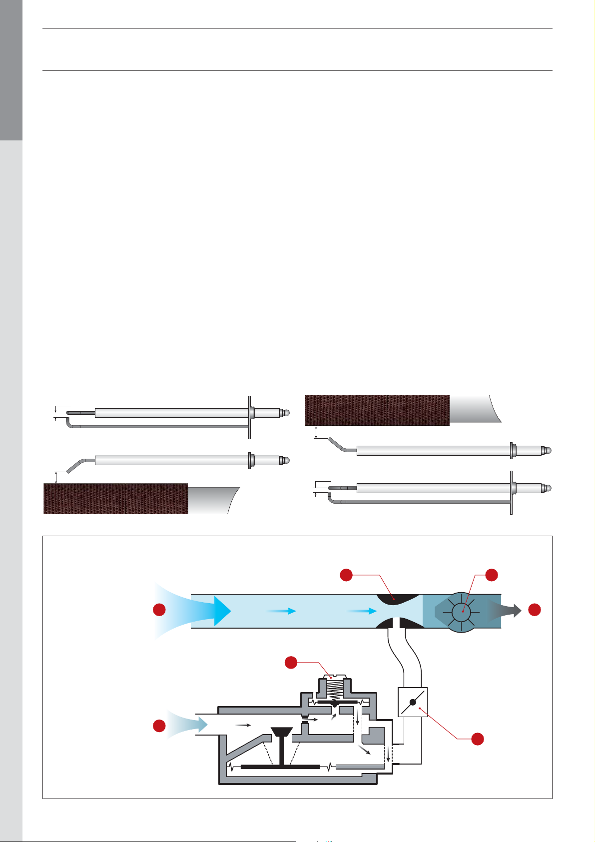
Gas pressure in the gas valve outlet is kept equal to the absolute
air pressure in the venturi tube inlet, corrected by the offset
adjustment on the regulator.
The fan pulls the combustion air through the venturi tube whose
neck is connected t o the gas valve outlet. The pressure differential
created at the neck of the venturi tube by the airflow rate induces
gas intake proportional to its level (the larger the air flow rate,
the greater the differential and there is a larger quantity of gas
intake). The air/gas combination is then introduced into the burner
via the fan.
HeatMaster® 71 - 101
This principle guarantees safe and quiet operation:
• In the event of low air flow, the differential across the
venturi tube falls, the gas flow rate diminishes, the flame
extinguishes and the gas valve closes: the burner is then in
safety mode.
• In the event of flue blockage or restriction, the air flow
rate falls, and there are then the same reactions as those
described before causing burner stop in safety mode.
®
• The BG 2000 -M burner installed on HeatMaster
controlled by a MCBA Honeywell controller which manages
both the burner safety function and its modulation according
to temperature.
HeatMaster® 201
models is
15
3 - 5
5
3 - 5
Air/gas mix control principle
C
A
D
E
F
A. Air
B. Gas
C. Venturi tube
D. Fan
E. Air - Gas mix
F. O ff se t a d j us t me n t s c r ew
G. Gas flow rate adjustment screw
664Y2500.B
B
G
EN • 20
Page 21
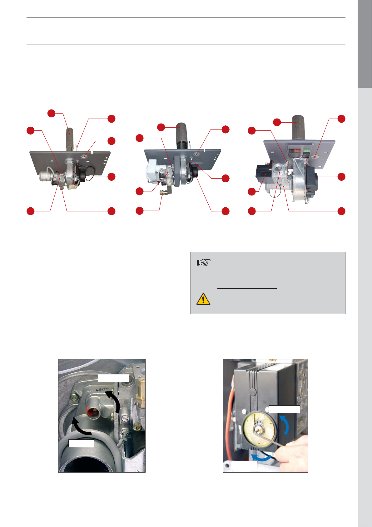
1. Bu r n e r t ub e
2. Ignition and ionisation electrode
3. Gas valve
4. Gas connection
5. Flame sight glass
6. Fan
7. V en t u r i t u be
BURNER CHARACTERISTICS
ENGLISHFRANCAISNEDERLANDSESPAÑOLITALIANODEUTSCH
BG 2000-M/71
BG 2000-M/101
1
2
7
5
7
1
6
3
3 4
4
Burner adjustment
When the burner operates at full power, the CO2 must be 8.8%
to 9.2% (natural gas) or 10.5% to 10.6% (propane).
If necessary adjust the CO2 by turning the screw in the
clock wise direction to reduce and the anti-clock wise to increase.
(see photo)
BG 2000-M/201
1
5
2
2
3
6
The BG 2000-M burners are pre-adjusted for
natural gas in the factory.
Conversion to propane:
4 7
5
6
BG 2000-M/71 - 101
Increase
Reduce
Prohibited in Belgium.
BG 2000-M/201
Increase
Reduce
664Y2500.B
EN • 21
Page 22

BRINGING INTO SERVICE
FILLING OF DHW AND HEATING CIRCUITS
ENGLISHFRANCAISNEDERLANDSESPAÑOLITALIANODEUTSCH
IMPORTANT
It is essential that the DHW cylinder is filled and
pressurised before filling the heating circuit.
1. Open the stop valve (1) and the outlet (8).
When the water flows from the outlet, the DHW cylinder is
filled and the outlet can be closed (8).
2. Fill the primary circuit (heating) and pressurise to 1 Bar.
3. Open the automatic air vent situated in the upper part of the
boiler.
IMPORTANT: the screw cap must be left loose to allow
future automatic venting to take place.
4. After venting the air from the system, bring the pressure up
to the static head plus 0.5 bar:
1.5 bar = 10m and 2 bar = 15 m.
5. Check that the electrical connection and the boiler room
ventilation are in accordance with the relevant standards.
2
3
12
6. Put the general switch to the ON position.
7. Adjust temperature set points via the MCBA display.
8. Check the gas supply pressure.
9. When the boiler is in operation, check that the flue
connections are gas tight.
10. After operating for five minutes, switch the boiler off and vent
the heating circuit again, maintaining a pressure of 1 bar.
11. Turn the appliance back on and check the combustion.
6
8
7
10
4
11
5
9
664Y2500.B
EN • 22
Page 23

MAINTENANCE
ANNUAL MAINTENANCE
ACV recommends that the boiler is inspected and serviced,
including the burner, at least once a year by a competent and
qu a l i f ied e n g i nee r...
More frequent servicing may be required depending on boiler
use, if this is the case consult your installer for advice.
BOILER MAINTENANCE
1. Turn the general switch on the control panel to OFF and
isolate the external electrical supply.
2. Close the gas supply valve.
Vertical flue gas outlet reduction:
3. Disengage and remove the flue connection to the boiler
4. Remove the flue reducer by un-tightening the nuts.
5. Extract the turbulators from the flue gas tubes for
cleaning.
6. Dismantle the fire door and withdraw the burner.
7. Brush the flue gas tubes.
8. Clean the combustion chamber and the burner.
9. Replace the turbulators, chimney reduction and flue
connection, and check that the seal on the flue reducer is in
good condition. Replace the seal if necessar y.
Horizontal flue gas outlet reduction:
Drainage of the heating circuit
1. Turn the general switch on the control panel to OFF position,
isolate the external electrical supply and close the gas
supply valve.
2. Close the isolation valves (4) or manually position the four
way valve (1) onto “0”.
3. Connect a flexible pipe to the drain valve (7).
4. Open the drain valve t o empty the primary circuit.
8
5
1
7
4
9
423
6
ENGLISHFRANCAISNEDERLANDSESPAÑOLITALIANODEUTSCH
3. Remove the cover from the flue reducer by un-tightening the
nuts.
4. Extract the turbulators from the flue gas tubes for
cleaning.
5. Dismantle the fire door and withdraw the burner.
6. Brush the flue gas tubes.
7. Clean the combustion chamber and the burner.
8. Replace the turbulators, chimney reduction and flue
connection, and check that the seal on the flue reducer is in
good condition. Replace the seal if necessar y.
MAINTENANCE OF SAFETY DEVICES
- Check that all thermostats and safety devices are working
well.
- Check the safety valves of the heating and DHW circuits.
BURNER MAINTENANCE
- Check that the insulation and seal of the fire door are in
good condition - replace them if necessary.
- Check and clean the boiler and the electrodes.
Replace the electrodes if necessary (once a year for normal
use).
- Check that the safety valves are in good work ing order.
- Check the combustion (CO
, CO and burner pressure).
2
Drainage of the DHW circuit
1. Turn the general switch on the control panel to OFF position,
isolate the external electrical supply and close the gas
supply valve.
2. Lower the heating circuit pressure until the pressure gauge
indicates zero bar.
3. Close the valves (1) and (8).
4. Open the valves (9) and (10) (first of all 9 then 10).
5. Allow the hot water to flow to the drain.
6
12
2
3
4
5
8
7
10
11
DRAINING OF THE BOILER
The water flowing from the drain valve is
very hot and can cause very serious burns.
Make sure that nobody is near the hot
water discharge.
664Y2500.B
9
The drain valve (9) must be at ground level to allow the
cylinder to drain.
EN • 23
Page 24

MCBA PARAMETERS FOR THE SPECIALIST
STANDBY MODE
ENGLISHFRANCAISNEDERLANDSESPAÑOLITALIANODEUTSCH
Standby Mode
When the boiler is switched on, it starts up in Stand-by mode, as
shown in the figure above.
This is the standard mode of the MCBA. The MCBA automatically
returns to this mode after 20 minutes if no key is pressed on
the display. When one or more parameters were stored, the new
parameters will become active.
The first digit indicates the boiler’s current status, depending
on the situation of the boiler and the burner. The last two digits
indicate the boiler temperature.
Status Boiler function
Standby, no heat demand
Fan pre-purge / post-purge
Ignition
Operation of the burner for heating
Once the cause of the blocking has been resolved, the burner
starts up automatically after a maximum of 150 seconds.
Status Boiler function
Internal adjustment — Three-way valve
Burner on for holding boiler warm
Test function: max RPM in CH mode
Test function: min RPM in CH mode
Test function: burner on with fixed fan speed
Operation of the burner for domestic hot water
Waiting for signal from the air pressure switch
or to obtain number of start revolutions
The burner is off because the set value has been
reached. There is still a demand for heat
Pump over run after the heating demand
Pump over run after the hot water demand
Blocked burner:
• : T1 > 95°C
•
•
•
•
•
•
•
•
•
•
: T2 > 95°C
: T2 - T1 > 10°C after 90 seconds
: dT1/dt > maximum gradient T1
: low water pressure switch not closed
: no tachometer signal
: erroneous tachometer signal
: T1 - T2 > Δ max.
: Short circuit NTC 3
: interruption NTC 3
: waiting for fan to start
If the burner is blocked for one of the above reasons, the screen
display alternates between 9 and the temperature (last two
digits) and b with the error code (last two digits).
664Y2500.B
EN • 24
Page 25

MCBA PARAMETERS FOR THE SPECIALIST
SETTING THE PARAMETERS
Parameter mode
To access Parameter mode when the system is in Standby mode, press the “MODE” key once.
To scroll through the list of parameters press “STEP”. To modify the value of the parameter, use the“+” or “-” keys.
Next, press the “STORE” to record the modified value. The screen will flash once to confirm the data has been saved.
To activate the modified parameters, press “MODE” key again (this will switch you to Info mode). However, if you do not press any key,
the system returns to Standby mode after 20 minutes and activates the changes.
Key Display
MODE
ENGLISHFRANCAISNEDERLANDSESPAÑOLITALIANODEUTSCH
Factory setting
Key Display Description of the parameters HM 71 HM 101 HM 201
Setting the hot water temperature
STEP
00 = Off
01 = On
00 = Off
01 = On
STEP
STEP
Hot water
generation
Switching
heating
On / Off
STEP
664Y2500.B
Maximum temperature in central heating mode
EN • 25
Page 26

MCBA PARAMETERS FOR THE SPECIALIST
INFORMATION ON THE INSTALLATION
ENGLISHFRANCAISNEDERLANDSESPAÑOLITALIANODEUTSCH
Info mode
To switch from Standby mode to Info mode,
press twice on “MODE”
Key Display
MODE
MODE
Key Display
T1 boiler temperature in °C
STEP
ENTERING THE CODE
Code mode
You can access the following parameters
by entering the service code:
• Parameters 5 through 42
• Communication mode
• Fan speed mode
• ERROR mode
Press the “STEP” key until you
see the desired information.
The dot located behind the
first position flashes to indicate
that the boiler is in Info mode.
To access Code mode, simultaneously press the MODE
and STEP keys. (Only from Stand-by mode!)
Description
of the parameters
MODE STEP
STEP
STEP
STEP
STEP
STEP
STEP
STEP
T2 boiler temperature in °C
Domestic hot water temperature
T3 in °C
Outside temperature T4 in °C
Not used
Calculated boiler
temperature in °C
Speed of increase of T1
temperature in °C/s
Speed of increase of T2
temperature in °C/s
Press STEP once and the screen indicates “C”
in the first position, then random characters
in the third and fourth positions.
STEP
Press on the “+” or “-” key to select the code.
+ -
Or
Press the STORE key and the screen flashes briefly
to indicate that the code has been accepted.
STORE
Press the MODE key until the desired mode appears.
STEP
STEP
664Y2500.B
Rate of increase of hot water
temperature in °C/s
Central heating
circuit temperature
[with AM3-11 module only]
Only ACV approved installers know the access code.
For more information, please contact our after-sales
service.
EN • 26
Page 27

MCBA PARAMETERS FOR THE SPECIALIST
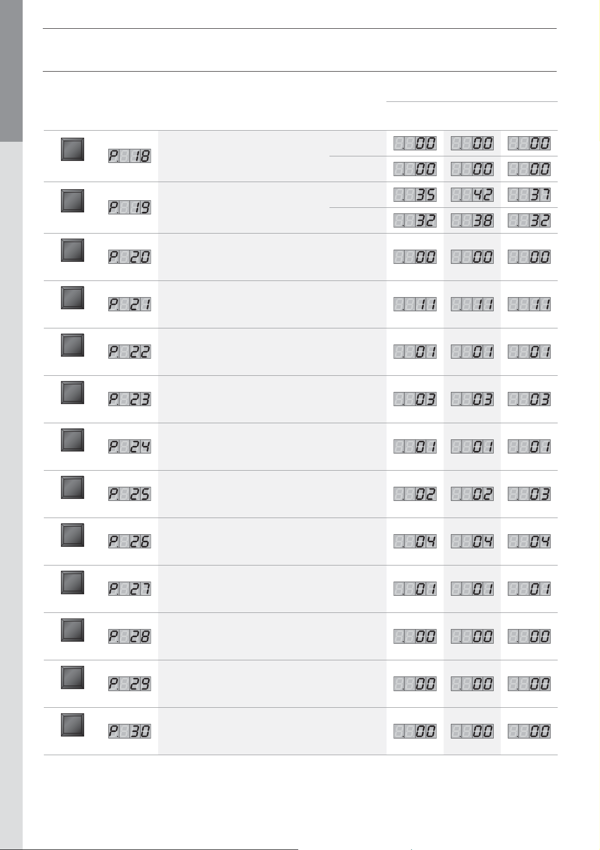
SETTING THE PARAMETERS:
Factory setting
only accessible with the code
Key Display Description of the parameters HM 71 HM 101 HM 201
Minimum boiler temperature using outdoor sensor
To avoid problems with the hot water function it is not
STEP
STEP
STEP
STEP
STEP
advised to adjust this parameter below 60°C
Minimum external temperature
[adjustment of the heating curve]
Maximum external temperature
[adjustment of the heating curve]
Frost protection temperature
Correction based on external temperature
ENGLISHFRANCAISNEDERLANDSESPAÑOLITALIANODEUTSCH
STEP
STEP
STEP
STEP
STEP
STEP
Tblocking 0 = Disabled
Booster 00 = Stop - [minute]
Night time central heating reduction (°C)
Natural gas
Max. fan speed in heating mode
[rpm x 100]
Propane
Natural gas
Max. fan speed in central heating mode
[rpm]
Propane
Natural gas
Max fan speed in domestic hot water mode
(rpm x 100)
Propane
STEP
STEP
664Y2500.B
Max fan speed in domestic hot water mode
Natural gas
(rpm)
Propane
Natural gas
Min. fan speed [rpm x 100]
Propane
EN • 27
Page 28
ENGLISHFRANCAISNEDERLANDSESPAÑOLITALIANODEUTSCH
Key Display Description of the parameters HM 71 HM 101 HM 201
STEP
STEP
STEP
STEP
MCBA PARAMETERS FOR THE SPECIALIST
Factory setting
Natural gas
Min. fan speed [rpm]
Propane
Natural gas
Max fan speed during ignition [rpm x 100]
Propane
Central heating pump over run
0 = 10 sec. [min.]
Domestic hot water pump over run
[sec. x 10.2]
STEP
STEP
STEP
STEP
STEP
STEP
STEP
CH hysteresis on
CH hysteresis off
DHW hysteresis on
DHW hysteresis on
DHW detection hysteresis on
DHW detection hysteresis off
Central heating block time [sec. x 10.2]
STEP
STEP
664Y2500.B
Domestic hot water block time [sec. x 10.2]
DHW ➙ CH blocking time [sec. x 10.2]
EN • 28
Page 29

MCBA PARAMETERS FOR THE SPECIALIST
Factory setting
Key Display Description of the parameters HM 71 HM 101 HM 201
Difference T1 - T2 for modulation
STEP
BUS -1address = de-activated
STEP
Increase of the primary temperature set point to generate
STEP
STEP
hot water
00 = high temperature circuit - circulator controlled by room
thermostat - DHW priority active.
50 = controlled circuit [external sensor and AM3-11 module]
- circulator controlled by the room thermostat - DHW priority
is not active.
ENGLISHFRANCAISNEDERLANDSESPAÑOLITALIANODEUTSCH
STEP
STEP
STEP
STEP
STEP
STEP
STEP
DHW production type:
This parameter cannot be modified
in any way on a HeatMaster
Manual fan speed (- 01 = modulation enabled)
Maintenance temperature
Maximum temperature of the heating circuit
(AM3-11 - four way valve)
Minimum temperature of the heating circuit
(AM3-11 - four way valve)
Heating circuit hysteresis temperature
(AM3-11 - four way valve)
®
Not used
STEP
664Y2500.B
1st position:
special pump [0 = disabled]
2nd position:
minimum disabling cycle [0 = disabled]
EN • 29
Page 30
MCBA PARAMETERS FOR THE SPECIALIST
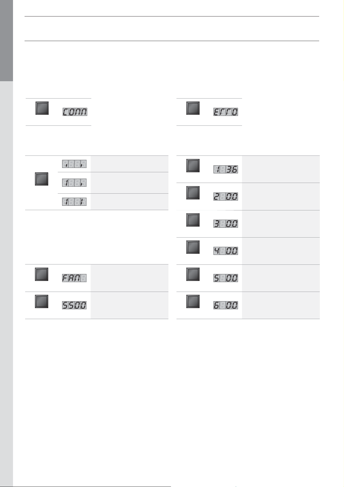
COMMUNICATION MODE [with code]
ENGLISHFRANCAISNEDERLANDSESPAÑOLITALIANODEUTSCH
This mode displays communication between the boiler
and the control module, the optional interface kit
or the optional programmable room thermostat.
Key Display
MODE
Key Display
STEP
of the parameters
No communication
Communication between
the boiler module and the
optional control module
Communication between all
the connected devices
Description
ERROR MODE [with code]
The ERROR mode indicates the most recent error, as well
as the status of the boiler and the temperature values at
the time of this error.
Key Display
MODE
Key Display
Error code at last lockout.
STEP
Status of the boiler at the time
of the error
STEP
Description
of the parameters
Fan mode [with code]
Key Display
MODE
STEP
Description
of the parameters
Fan speed
The fan’s current speed
is 5500 rpm.
T1 temperature at the time
of the error
STEP
T2 temperature at the time
of the error
STEP
Hot water temperature T3
at the time of the error
STEP
Outdoor temperature T4
at the time of the error
STEP
664Y2500.B
EN • 30
Page 31

MCBA PARAMETERS FOR THE SPECIALIST
LIST OF ERROR CODES + SOLUTIONS
[in ERROR mode]
If a fault occurs during operation, the system locks out
and the screen starts to flash.
The first character is an “E” and the following two indicate
the fault code, as indicated in the table below.
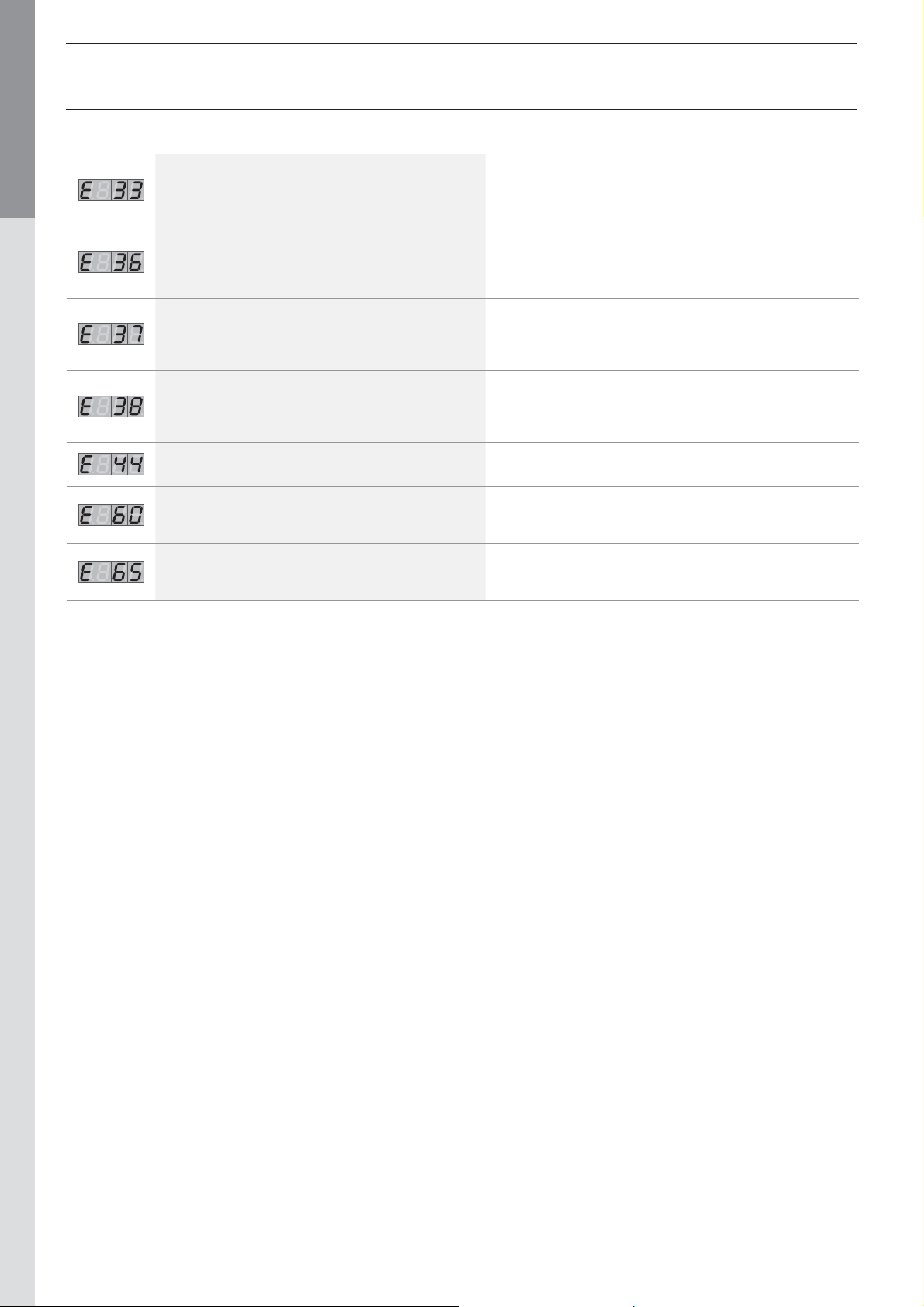
Codes Description of the fault Resolution of the fault
Abnormal flame signal detected
No flame presence after five start-up attempts
Rectifier or gas valve error Replace the rectifier or gas valve
Persistent lockout Press “RESET”
Internal error
EPROM error
To unlock the system:
• Press “RESET” on the screen.
• If the fault is repeated continually, contact your
installer.
- Check the wiring (short circuit in the 24V wiring)
- Check the electrode
- Replace the MCBA (water damage)
- Check the ignition wiring
- Check the electrode and its position
- Check the gas supply to the burner
If the problem persists after two “RESET” attempts,
replace the MCBA
If the problem persists after two “RESET” attempts,
replace the MCBA
ENGLISHFRANCAISNEDERLANDSESPAÑOLITALIANODEUTSCH
- If the primary water pressure is lower than 0.5 bar,
Low water safety or 24 V fuse damaged
Internal error
T1 > 110°C
T2 > 110°C - Check the NTC wiring and replace it if necessary
T1 gradient too high
No tachometer signal from the fan
The fan’s tachometer signal does not drop back to “0”
re-establish the pressure to a minimum of 0.8 bar
by adding water to the system
- Check the wiring
- Check the 24 Volt fuse of the MCBA
If the problem persists after two “RESET” attempts,
replace the MCBA
- Check the NTC wiring and replace it if necessary
- If the NTC 1 sensor is OK, check if there is water flow
in the boiler
- Check if the pump is running
- If there is no problem with the pump, vent the system
- Check the PWM connection
- Check the fan’s wiring
If the problem persists after two “RESET” attempts,
replace the fan, otherwise, change the MCBA
- Check the draft in the chimney.
If the draught is correct replace the ventilator
664Y2500.B
Short circuit NTC 1
Short circuit NTC 2
- Check the connection of the NTC 1 sensor
- Check the wiring of the NTC 1 sensor
If the problem persists replace the NTC 1 sensor
- Check the connection of the NTC 2 sensor
- Check the wiring of the NTC 2 sensor
If the problem persists, replace the NTC 2 sensor
EN • 31
Page 32
Codes Description of the fault Resolution of the fault
ENGLISHFRANCAISNEDERLANDSESPAÑOLITALIANODEUTSCH
MCBA PARAMETERS FOR THE SPECIALIST
- Check the connection of the NTC 3 sensor
Short circuit NTC 3
NTC 1 connection open
NTC 2 connection open
NTC 3 connection open
- Check the wiring of the NTC 3 sensor
If the problem persists replace the NTC 3 sensor
- Check the connection of the NTC 1 sensor
- Check the wiring of the NTC 1 sensor
If the problem persists replace the NTC 1 sensor
- Check the connection of the NTC 2 sensor
- Check the wiring of the NTC 2 sensor
If the problem persists replace the NTC 2 sensor
- Check the connection of the NTC 3 sensor
- Check the wiring of the NTC 3 sensor
If the problem persists replace the NTC 3 sensor
Internal error
Error during reading of the parameters
Fan power supply problems
If the problem persists after two “RESET” attempts,
replace the MCBA
Press RESET
If the error persists, replace the MCBA
- Check the supply voltage of the MCBA
If you detect no problems with it, replace the fan
664Y2500.B
EN • 32
Page 33

51700034
BG 2000 - M / 71
537DZ029
51700025
21479369
55412000
557A0026
55700026
50423365
557A0012
257F1108
537DZ020
257F1073
537D3027
537D4028
537D6135
537D4037
537D4033
557D6039
537D3017
664Y2500.B
Page 34
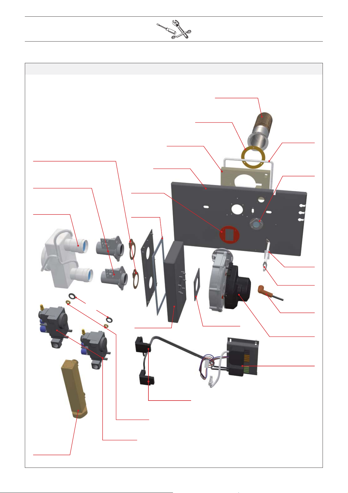
BG 2000 - M / 101
557A0020
537DZ019
557A0026
537D4028
507F4008
557D6039
55700026
557A0025
557A0021
21479370
51700025
50423365
557A0012
537DX020
257F1073
507F4007
664Y2500.B
537D4037
537D4033
2147B369
557A0019
537D3033
257F1107
537D3016
Page 35

BG 2000 - M / 201
537DZ019
537DX021
557A0012
557A0020
2147P416
50423365
557A0040
257F1105
537D3034
43726007
42714000
257F1069
557A0045
537D8022
664Y2500.B
Page 36

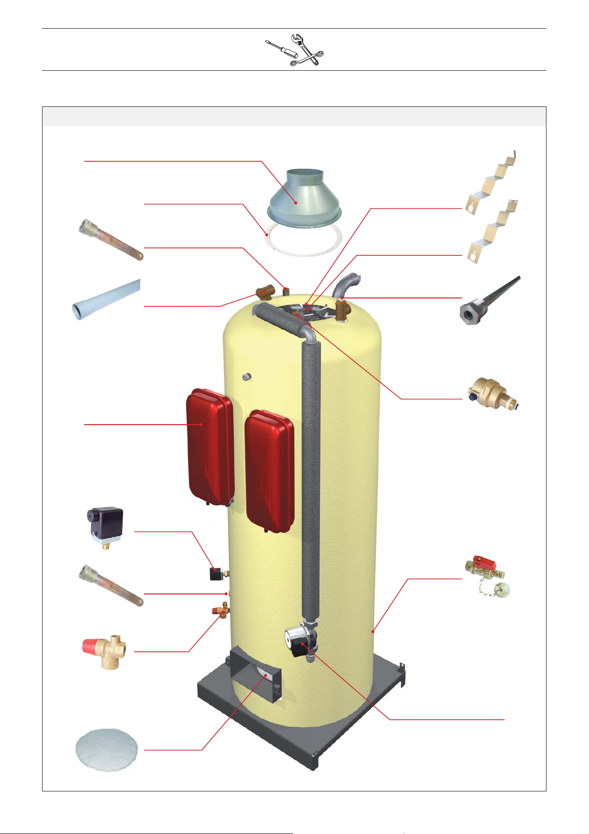
21472369
21473369
HeatMaster® 71
21475369
21474369
21477370
21478369
21476369
21471369
664Y2500.B
Page 37
507F3033
HeatMaster® 71
557A7006
557A0016
63438001
497B0001
8 x 507F2009
16 x 507F2010
39438046
55445007
557A1056
63438001
55426017
51305000
55426001
557A4009
664Y2500.B
Page 38

21472370
21473370
HeatMaster® 71
HeatMaster® 101
21475369
21474370
21477370
21478369
21476369
21471370
664Y2500.B
Page 39

507F3033
HeatMaster® 101
557A7006
557A0016
63438001
49410071
8 x 507F2009
24 x 507F2010
39438047
55445007
557A1056
63438001
55426017
51305000
55426001
557A4009
664Y2500.B
Page 40
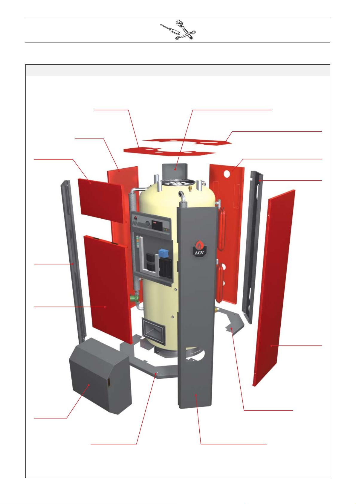
HeatMaster® 201
2147A415
21479415
21471415
21475416
21473415
21475415
21474415
21478415
2147B415
21476416
2147S415
21471415
2147S415
21472415
664Y2500.B
Page 41

507F3044
HeatMaster® 201
557A0059
557A0055
8 x 507F2009
39438030
24 x 507F2010
497B0502
63438001
557A3001
557A4007
557A1056
63438001
51700041
55301200
55301200
557A1048
557A1000
51700040
664Y2500.B
557A4007
Page 42
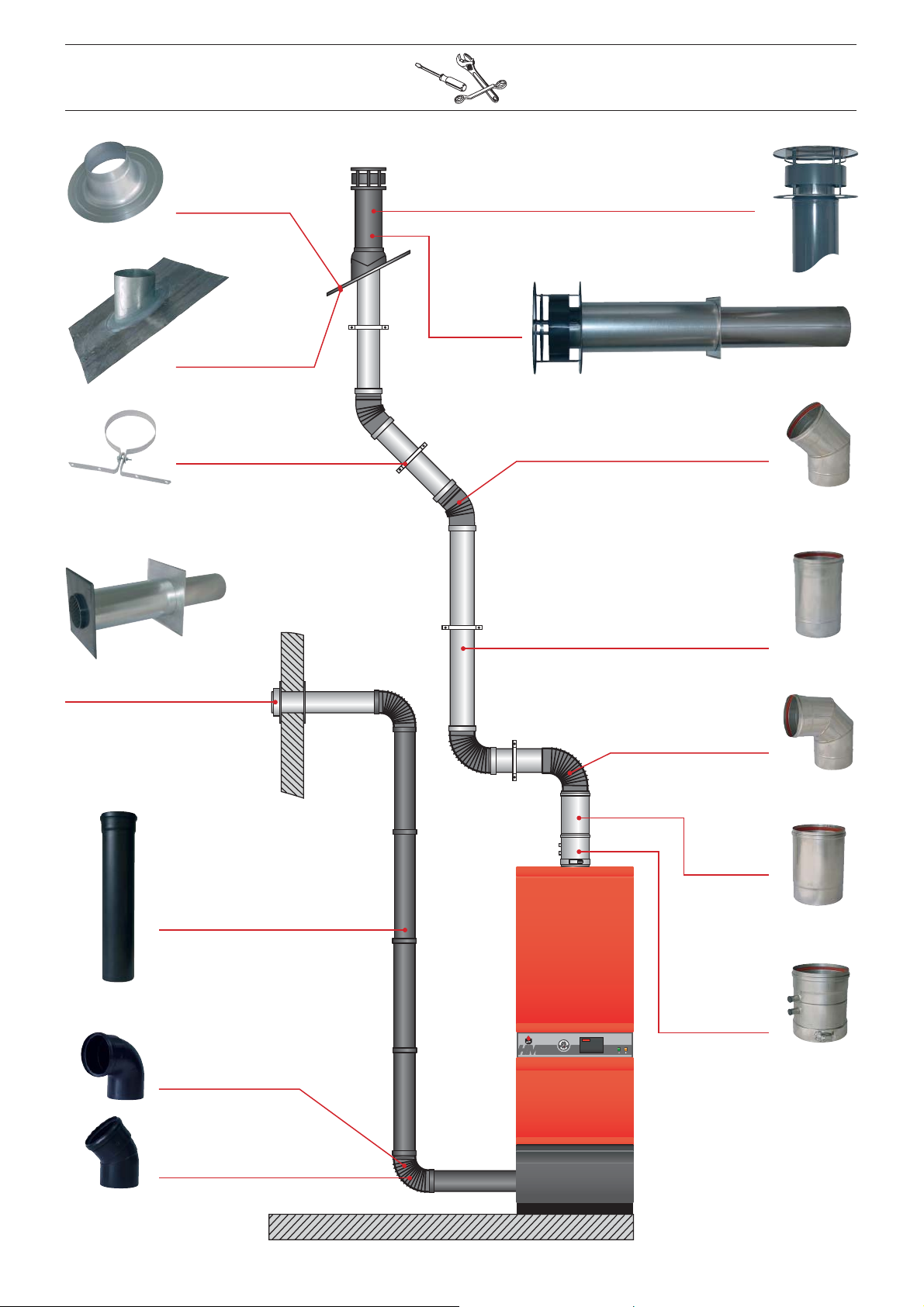
537D6224
Ø 150 mm
537D6225
Ø 150 mm
537D6211
Ø 150 mm
537D6212
Ø 150 mm
537D6213
Ø 100 mm
537D6210
Ø 150 mm
537D6219
Ø 150 mm - 45°Mm
537D6214
Ø 150 mm - L 250 mm
537D6215
Ø 150 mm - L 500 mm
537D6216
Ø 150 mm - L 1000 mm
537D6219
Ø 150 mm - 90°
537D6218
Ø 150 mm
664Y2500.B
537D6217
Ø 100 mm - L 500 mm
537D6223
Ø 150 mm
537D6222
Ø 100 mm - 90°
537D6222
Ø 100 mm - 45°
Page 43

HeatMaster® 71 / 101
54441008
537D3020 54766016 54766017
537D3023
547D3021
664Y2500.B
AM3-2
10800060
HM 71 : 537D8037
HM 101 : 537D8038
AM3-11
10800080
Page 44

54441008
HeatMaster® 201
537D3020 54766016 54766017
537D3023
54452082
AM3-11
10800080
547D3021
537D8039
664Y2500.B
AM3-2
10800060
 Loading...