

Page 1
®
HeatMaster
Assembling and installation instructions
HeatMaster® 201 Booster
HeatMaster® 200N (Gas) Booster
ENGLISHFRANCAISNEDERLANDSESPAÑOLITALIANODEUTSCH
664Y2900.C
EN • 1
Page 2
INDEX
WARNINGS 3
Who should read these instructions 3
Symbols 2
ENGLISHFRANCAISNEDERLANDSESPAÑOLITALIANODEUTSCH
Applicable standards 2
Recommendations 2
Warnings 2
DESCRIPTION 3
Packing 3
Technical characteristics 3
Hydraulic connections 3
Dimensions 3
WHO SHOULD READ THESE INSTRUCTIONS
These instructions should be read by:
- the specifying engineer
- the installer
- the user
- the service engineer
SYMBOLS
The following symbols are used in this manual:
Essential instruction for the correct operation of
the installation.
Essential instruction for the safety of persons
and the environment.
ELECTRICAL CONNECTION 4
HeatMaster 201: serial number > at 1000 4
HeatMaster 201: serial number < at 1000 4
HeatMaster 200N 6
BOOSTER KIT ASSEMBLY 7
WARNINGS
• The product must be installed and serviced by trained
engineers, in compliance with current standards.
• Any failure to follow instructions relating to tests and test
procedures may result in personal injury or risks of pollution.
• To guarantee safe and correct operation of the appliance, it
is important to have it serviced and maintained every year by
an approved installer or maintenance company.
• In case of anomaly, please call your service engineer.
• Despite the strict quality standards imposed by ACV during
the manufacture, inspection and transport of its appliances,
you might notice some errors. Please report immediately any
fault to your approved installer.
• The parts may only be replaced by genuine factory parts. You
will find a list of the spare parts and their ACV reference
number at the end of this document.
Danger of electrocution.
APPLICABLE STANDARDS
The appliances carry the CE mark in accordance with the
standards in force in the various countries (European Directives
92/42/EC “Efficiency”, 90/396/EC “Gas appliances”).
They also carry the “HR Top” label (Gas boilers).
RECOMMENDATIONS
• Please, carefully read this manual before installing and
commissioning the boiler.
• It is prohibited to carry out any modifications to the inside of
the appliance without the manufacturer’s prior and written
agreement.
WARNINGS
This documentation is part of the information delivered with the
appliance and must be given to the user and stored in a safe
place!
An approved installer must carry out the assembly, commissioning,
maintenance and repair of the system, in accordance with current
standards in force.
ACV shall not accept any responsibility for damage caused by
non-compliant location of the system or by use of the parts or
connections not approved by ACV for this application.
The manufacturer reserves the right to change the
technical characteristics and specification of its
products without notice.
The availability of some versions and their accessories
is market dependant..
664Y2900.C
EN • 2
Page 3
DESCRIPTION
PACKING
The HeatMaster® 200N / 201 Booster
are delivered in several packing:
Pack 1 : HeatMaster insulated body with control panel.
Pack 2 : Complete jacket
Pack 3 : Chimney reduction with horizontal exhaust and gasket.
Pack 4 : Low temperature hydraulic kit including 4-ways valve,
tubes and hydraulic components.
Pack 5 : Motor and temperature sensor kit (to control the
4-ways valve).
Pack 6 : Booster kit including the Booster, bracket and holder,
tubes and hydraulic components for the heating and
shunt loops.
Pack 7 : Gas burner with insulation and gasket
(only HeatMaster 201).
TECHNICAL CHARACTERISTICS
Heating Mode
HeatMaster® 201 Booster
- Input: 220,0 kW
- Output: 210,1 kW
- 100% load efficiency - 80/60 mode: 95,5%
- 100% load efficiency - 50/30 mode: 106,1%
- 30% load efficiency - return at 30°C: 107,9%
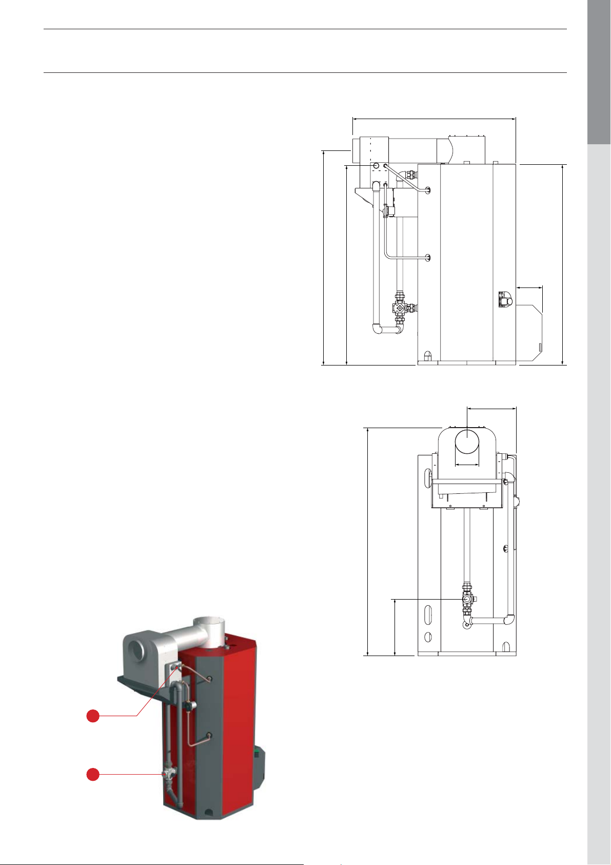
DIMENSIONS
2224
2070
1696
ENGLISHFRANCAISNEDERLANDSESPAÑOLITALIANODEUTSCH
2085
274
Hot water mode - set point 90°C
HeatMaster® 201 Booster
- Input: 240,0 kW
- Output: 225,0 kW
- Continuous flow rate at 40°C cold water at 10°C: 6425 l/h
Pressure drops (Booster alone)
- Hydraulic (ΔT = 20): 20 mbar
- Flue gas circuit: 0,3 mbar
HYDRAULIC CONNECTIONS
A. Heating return Ø 2” M
B. Heating f low Ø 2”
510
250
2370
590
664Y2900.C
A
B
EN • 3
Page 4

ELECTRICAL CONNECTION
t
BUS
S
O
t
P
1211
10
8
7
M
3
M
15
1
18
2
Bl
Y/Gr
Bl
Y/Gr
Bl
Y/Gr
HeatMaster® 201:
ENGLISHFRANCAISNEDERLANDSESPAÑOLITALIANODEUTSCH
serial number > at 1000
Flow sensor (14)
- Mount the NTC6 sensor on the flow tube.
- Connect the sensor to the 15 and 16 terminals.
Heating pump (16)
Connect the heating pump on the terminal block:
line voltage to 07, neutral to 08 and ground to 09.
Motor of the 4-ways valve (20)
- Connect the ground to 19.
- Connect the brown wire to 20 (closing contact)
- Connect the blue wire to 21 (neutral)
- Connect the black wire to 22 (Opening contact)
Booster shunt pump (19)
- Connect the line connection of the Booster shunt pump to
16, the neutral to 17 and the ground to 18.
16
19
7
20
Y/Gr
Y/Gr
M6
M2
M
M5
X2
01
02
03
04
05
R
M
Bl
4
R
M
Bl
Y/Gr
N
M
3
06
07
08
09
10
11
12
13
14
15
16
17
18
19
20
21
22
23
24
25
26
27
28
X3
01
02
03
04
05
06
07
08
09
10
11
12
13
14
15
16
17
18
19
BU
14
B
A
Vol
9
664Y2900.C
EN • 4
Page 5

ELECTRICAL CONNECTION
t
BUS
S
O
t
P
1211
10
8
7
M
3
M
15
1
18
2
Bl
Y/Gr
Bl
Y/Gr
Bl
Y/Gr
HeatMaster® 201:
serial number < at 1000
Flow sensor (14)
- Mount the NTC6 sensor on the flow tube.
- Connect the sensor to the 15 and 16 terminals.
Heating pump (16)
Connect the heating pump on the terminal block:
line voltage to 07, neutral to 08 and ground to 09.
Motor of the 4-ways valve (20)
- Connect the ground to 16.
- Connect the brown wire to 17 (closing contact)
- Connect the blue wire to 18 (neutral)
- Connect the black wire to 19 (Opening contact)
Booster shunt pump (19)
- Connect the line connection of the Booster shunt pump to
13, the neutral to 14 and the ground to 15.
16
19
7
20
Y/Gr
Y/Gr
M6
M2
M
M5
X2
01
02
03
04
05
R
M
Bl
4
R
M
Bl
Y/Gr
N
M
3
06
07
08
09
10
11
12
13
14
15
16
17
18
19
20
21
22
23
24
25
ENGLISHFRANCAISNEDERLANDSESPAÑOLITALIANODEUTSCH
X3
01
02
03
04
05
06
07
08
09
10
11
12
13
14
15
16
17
18
19
BU
14
B
A
Vol
9
664Y2900.C
EN • 5
Page 6

ELECTRICAL CONNECTION
9
L1N
T1T2S3B
S3
N
L1N
O
C
C
C
HeatMaster® 200N
ENGLISHFRANCAISNEDERLANDSESPAÑOLITALIANODEUTSCH
The terminals numbering refer to the control panel of the
HeatMaster® 200N
- Connect terminals 9 and 10 to the solenoid of the reversing
relay (18). (optional)
- Connect terminal 12 to the common of the relay (18).
- Connect the neutral of the Booster shunt pump (19) to
terminal 10.
- Connect the hot line of the Booster shunt pump (19) to the
“normally closed” terminal of the relay (18).
19
18
1 2 3 4 5 6 7 8 9 1011121314151617181920212223
Base for relay and reversing relay
ACV code:
54428195 : base relay
54428220 : reversing relay
4
11
7
03
5
16
- 90
7
L1
664Y2900.C
EN • 6
Page 7

BOOSTER KIT ASSEMBLY
1. Replace the two plugs located on the T - of both expansion
vessels to the right of the boiler by two 3/4” - 1” reducers.
5. Mount the two M-M union
6. Mount a 90° elbow on the upper
connexion and the 4-ways valve on the
lower one.
Mount the M-F union connexion on
the 4-ways-valve; place the 2” tube
between the 90° elbow and the 4-ways
valve. This 2” tube must be perfectly
vertical : if necessary, adjust the
position of the 90° elbow and/or the
4-ways valve.
connections on the flow
and the return of the
boiler-body.
ENGLISHFRANCAISNEDERLANDSESPAÑOLITALIANODEUTSCH
2. Fix the two Booster mounting legs on the brackets located on the
back side of the HeatMaster with four M10 screws.
3. Punch the pre-cut parts
from the rear panel
4. Put the rear panel in place.
7. Fix the Booster holder on the mounting legs with four M10 bolts.
664Y2900.C
8. Place the Booster on its
holder
EN • 7
Page 8

BOOSTER KIT ASSEMBLY
9. - Place the back right side panel.
- Connect the the upper tube of the Booster shunt loop.
ENGLISHFRANCAISNEDERLANDSESPAÑOLITALIANODEUTSCH
10. Mount a 90° elbow on the
lower nipple of the Booster.
13. Mount the second 2” tube
with the left hand thread
on the coupling. Leave
some threads for later
adjustment.
14. Mount the 90° elbow on the
2”tube.
11. On this elbow, mount the
2" tube with the two righthand threads.
Pay attention to the
threads : one tube has a
left-hand thread.
12. On this 2" tube, mount the
left hand and right hand
threaded coupling; screw
it half-way to leave the
adjustment.
15. Mount the third 2” tube
with the 90° elbow and the
union connexion.
16. Ensure that the union
connection is aligned with
the 4-ways valve.
664Y2900.C
EN • 8
Page 9

BOOSTER KIT ASSEMBLY
17. Adjust the RH / LH
coupling to mate the faces
of union connection.
18. Tighten the union
connexion.
20. Mount the 6 studs on the
flange and put the gasket
in place.
21. Locate the flue collector
hood and fit it together with
the flue tube of the Booster.
Fix the flue collector with
the nuts.
22. Fit the condense trap on
the Booster condense
outlet.
ENGLISHFRANCAISNEDERLANDSESPAÑOLITALIANODEUTSCH
19. Connect the shunt
pump with its upper and
lower tube between the
HeatMaster and the
Booster.
23. Overall picture.
664Y2900.C
EN • 9
Page 10

24. Hydraulic connexion of the heating system.
ENGLISHFRANCAISNEDERLANDSESPAÑOLITALIANODEUTSCH
BOOSTER KIT ASSEMBLY
M5
25. Electric connexion of the shunt pump (M5) : see pages 4, 5
and 6.
26. Commissioning of the system and control of the complete
installation : see HeatMaster 200N / 201 technical manual.
664Y2900.C
EN • 10
 Loading...