

Page 1
excellence in hot water
Installation, Operating and
Servicing Instructions
HeatMaster
®
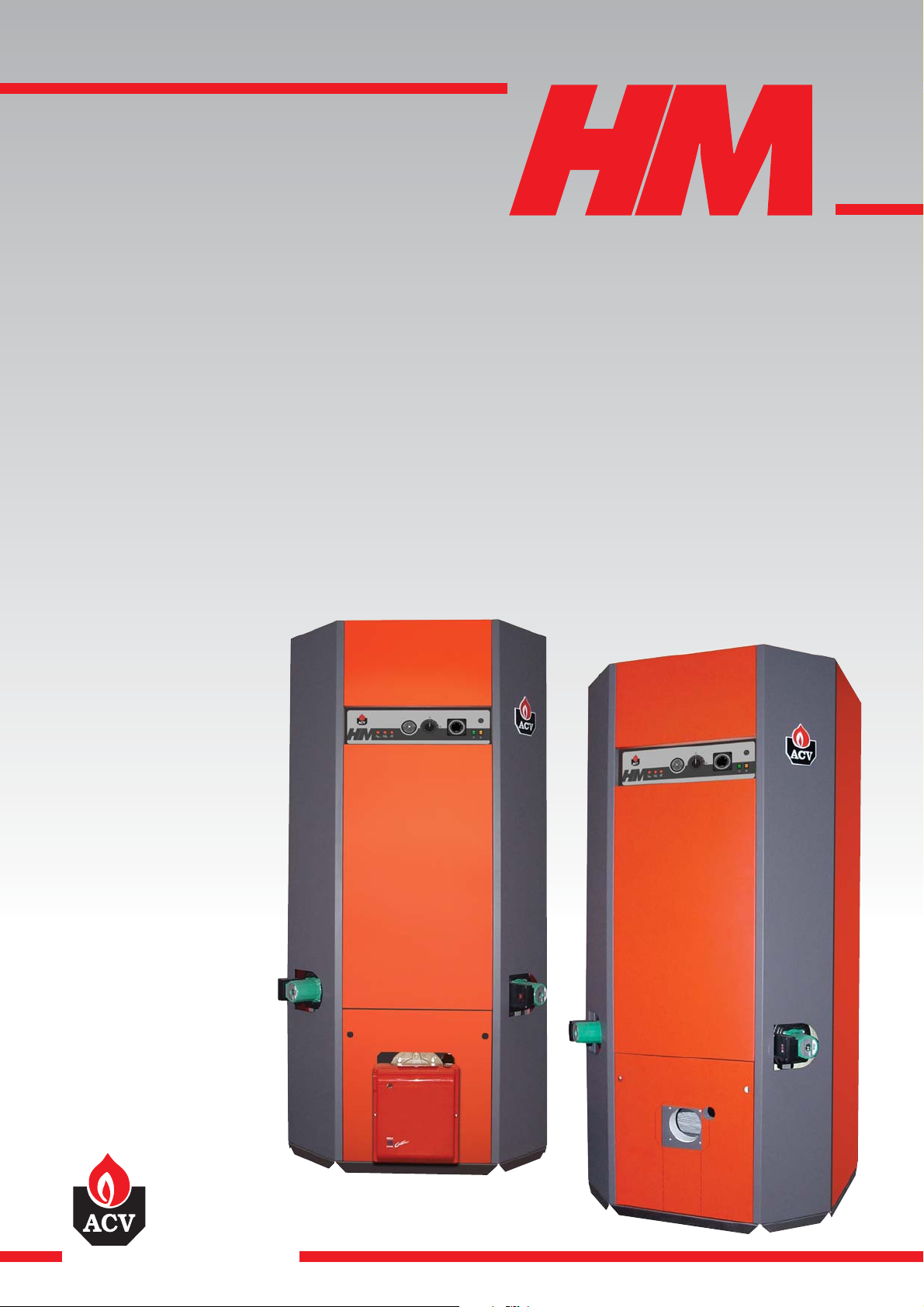
HeatMaster®200 N
HeatMaster®200 F
28/09/2005 - 66402600.B
Page 2

Page 3
1
INDEX INTRODUCTION
INTRODUCTION 1
Target group 1
Symbols 1
Certification 1
Information and safety instructions 2
USER GUIDE 2
Use of the boiler 2
DESCRIPTION 3
Operating principle 3
Packing 3
Construction features 4
TECHNICAL SPECIFICATION 5
Effective dimensions 5
General characteristics 5
Hot water output data 6
Limits of operating conditions 6
Burner chamber plate 6
INSTALLATION 7
Boiler room 7
Chimney connections 7
Hot water connections 8
Heating connection 9
Oil supply connections 9
Electrical connections 10
Wiring diagram 10
COMMISSIONING 11
Filling the hot water and heating circuits 11
MAINTENANCE 11
Service intervals 11
Servicing the boiler 11
Servicing the safety devices 11
Servicing the burner 11
Draining the boiler 12
SAFETY MODE 12
Placing the burner in safety mode 12
Placing the boiler in safety mode 12
SPARE PARTS 13
Jackets 13
Accessories 13
SERVICE RECORD 14
Details of the installation 14
Service notes 14
CERTIFICATION
The appliances carry the “CE” mark, in accordance with the
standards in force in the various countries (European Directive
92/42/CEE “Efficiency”).
TARGET GROUP
This manual is intended for the use of:
- final users of the appliance;
- the engineer installing and starting up the appliance;
- the engineering and design department;
- the installer responsible for servicing or maintaining the appliance.
SYMBOLES
The following symbols are used in this manual:
DANGER
HOT
Essential instruction for operating the system
correctly.
Risk of scalding.
Danger of electrocution.
Essential instruction for personal safety or
environmental protection.
Page 4
2
INTRODUCTION USER GUIDE
USING THE BOILER
It is compulsory to have your system serviced every
year by a competent engineer. In the event of heavy
use of the boiler, it may require servicing on a more
regular basis than once a year. In this case, contact
your installer for advice.
Starting the burner
In conditions of normal operation, the burner starts automatically if
the temperature of the boiler is below the set point and goes off
when this value is reached.
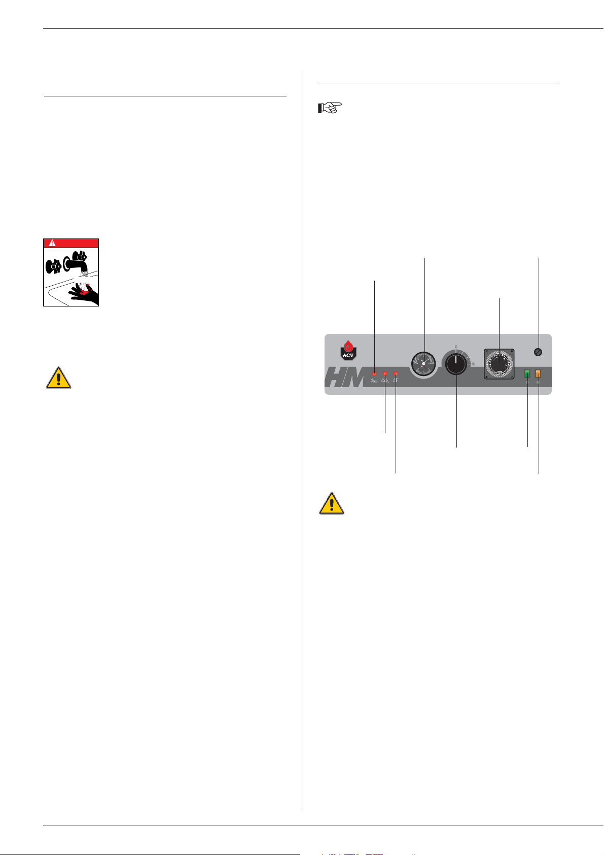
Control panel
The user must not attempt to gain access to the
components inside the control panel.
1. On/Off switch
This turns the HeatMaster on or off.
2. Control thermostat - 60 to 90°C
When using the HeatMaster
®
as a hot water generator only, the
temperature can be set between 60°C and 90°C.
If the HeatMaster
®
is used for both hot water and central heating, the
control thermostat would normally be set at 80°C to achieve optimum
operating conditions.
3. Summer/Winter switch
This turns the heating pump
(if fitted)
on or off.
4. Manual reset high limit thermostat
If the boiler temperature exceeds 103°C this safety device will
activate and the high temperature indicator will light up. To reset first allow the boiler to cool to below 60°C, unscrew the cap and
press the reset button using a pencil or similar pointed device,
replace the cap. If the fault persists, turn the boiler off and call an
engineer.
GENERAL INFORMATION
AND SAFETY INSTRUCTIONS
General information
This documentation forms part of the items delivered with the
appliance and must be given to the user to keep in a safe place!
This appliance must be serviced and repaired by an approved
installer, in accordance with current standards in force.
ACV declines all liability for any damage caused as a result of
incorrect installation or as a result of the use of components or
connections that are not approved by ACV for this application.
Temperatures
This boiler is designed for central heating systems
with a maximum outlet temperature of 90°C.
Therefore, the central heating pipelines and the
radiators must reach this temperature.
The waste-gas pipe lines must reach
temperatures in excess of 100°C.
The hot water can reach temperatures in excess
of 60°C.
Installation
Before installing and commissioning the boiler, first
carefully read this manual.
Position the HeatMaster®according to the safety rules and
standards in force. You must comply with the ventilation
requirements for the room where appliances of this type are
installed. All air vents must remain unobstructed at all times.
It is prohibited to modify the interior of the appliance in any way,
without the manufacturer’s prior written agreement.
Service
In order to ensure the appliance operates safely and correctly, it is
important to have it serviced and reconditioned every year by an
installer or an approved service company.
Faults
Despite the strict quality standards imposed on its appliances by
ACV during production, inspection, and transport, faults may occur.
Please immediately inform your approved installer about such faults.
Only genuine factory parts may be used as replacement parts.
Please go to page 13 for a list of spare parts and their ACV
reference numbers.
Important note: ACV reserves the right to change the technical
characteristics and specification of its products without notice.
DANGER
HOT
Manual reset high
limit thermostat
Burner
lockout
indicator
Combined temperature
and pressure gauge
Time clock
Control
thermostat
ON / OFF
switch
Primary circuit low
water pressure
indicator
High limit cutoff
indicator
Summer / Winter switch
I
O
Page 5
5. Time clock
This allows the HeatMaster
®
to be timed on and off and operates on
a 24 hour sequence. Around the outside of the clock there are a
number of white tabs, these allow 15 minute switching periods. To
set the time clock simply push outwards the number of tabs required
for ON period.
Remember: TAB IN = HeatMaster OFF
TAB OUT = HeatMaster ON
6. Temperature and pressure gauge
This gauge indicates both the temperature of the HeatMaster
®
and
the pressure within the primary circuit.
The temperature should not exceed 90°C - if it does, switch the
boiler off and check the thermostat setting. If the fault persists, call
an engineer.
The pressure should not fall below 1bar, if it does the please see the
'Heating System Pressure' paragraph later in this section.
7. Low primary water pressure indicator
If this indicator lights up, the primary circuit of the HeatMaster
®
requires topping up with water. Please see the 'Heating System
Pressure' paragraph later in this section.
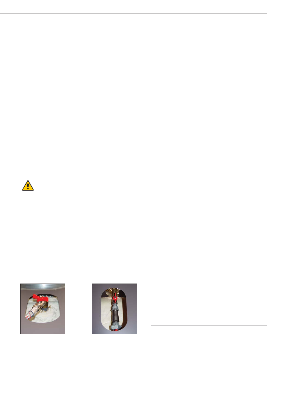
Heating-system pressure
The heating circuit may require a top-up of water. The pressure
gauge, located beside the display, gives the pressure.
In the case of repeated fills, contact your installer.
The pressure of the primary circuit must be at least 1 bar and must
be regularly checked by the end user. If the pressure falls below
0.5 bar, the low-water-level pressure switch locks the appliance until
the pressure in the system returns to above 0.8 bar.
The HeatMaster
®
200 N / 200 F is fitted with a purpose-designed fill
set
(see Fig. A and B)
. Always make sure that the appliance is
switched off when filling the system.
To do this, turn the On/Off switch on the left of the control panel to
Off.
For more information, please ask your installer when delivering the
system.
The appliance is fitted with a safety valve. If the system pressure
exceeds 3 bars, this valve opens and drains the water from the
system. In this case, contact your installer.
3
USER GUIDE DESCRIPTION
OPERATING PRINCIPLE
The HeatMaster®is a high performance, direct fired hot water
storage heater, which has indirect heat transfer due to its Tank-inTank construction.
At the heart of the HeatMaster
®
is a stainless steel cylinder through
which the flue tubes pass. This is surrounded by a mild steel shell
containing the primary water (neutral fluid). The outer shell extends
down to the combustion chamber and even around the flue tubes.
The area of the heat transfer surface is therefore much greater than
that of standard direct fired water heaters.
A circulating pump fitted to the primary circuit moves the water
around the tank, heating it faster and maintaining an even
temperature across the primary jacket.
The burner, either gas or oil, fires onto the primary water which
indirectly heats the stainless steel cylinder containing the DHW. As
with all Tank-in-Tanks, this is corrugated over its full height and
suspended in the HeatMaster
®
by its hot and cold water
connections.
The cylinder expands and contracts during use and this, together
with the fact that cold water does not come into contact with the
intense heat of the burner flame, means that limescale buildup is
prevented.
This scale resistant feature, along with the corrosion resistance of
stainless steel, eliminates the need for sacrifical anodes.
The HeatMaster
®
has one very major advantage over other direct
fired water heaters - because it heats the DHW with a primary
circuit, this primary water can be used to provide central heating as
well.
By connecting two, three, four or more HeatMaster
®
together in a
module, most hot water and heating demands can be met.
Indeed, when used in conjunction with HR and Jumbo hot water
storage tanks the HeatMaster can supply even the largest hot water
requirement.
Standard equipment
The HeatMaster 200 has the following items as standard:
- On/off switch
- Summer/Winter switch
- Control thermostat (60 - 90°C)
- Thermal reset high-limit thermostat (95°C)
- Manual reset high-limit thermostat
- Hot water priority thermostat
- Primary circulating shunt pump
- Primary expansion vessels
- Primary safety valve
- Pressure and temperature gauge
- Drain valve
- Body completely insulated in rigid polyurethane foam
PACKING
The HeatMaster is delivered in separate packages.
• Package No. 1: Foam-insulated body, hydraulic accessories,
and control panel.
• Package No. 2: Chimney reducing pipe.
• Package No. 3: Wooden protective casing (jacket and
accessory).
• Package No. 4: “RIELLO” RG4S 396 T1 burner
(HM 200 F only).
Fig. A
(cover)
Fig. B
(rear panel)
Page 6
4
DESCRIPTION
19
20
21
17
18
15
16
10
11
12
13
14
8
9
6
7
5
1
3
4
2
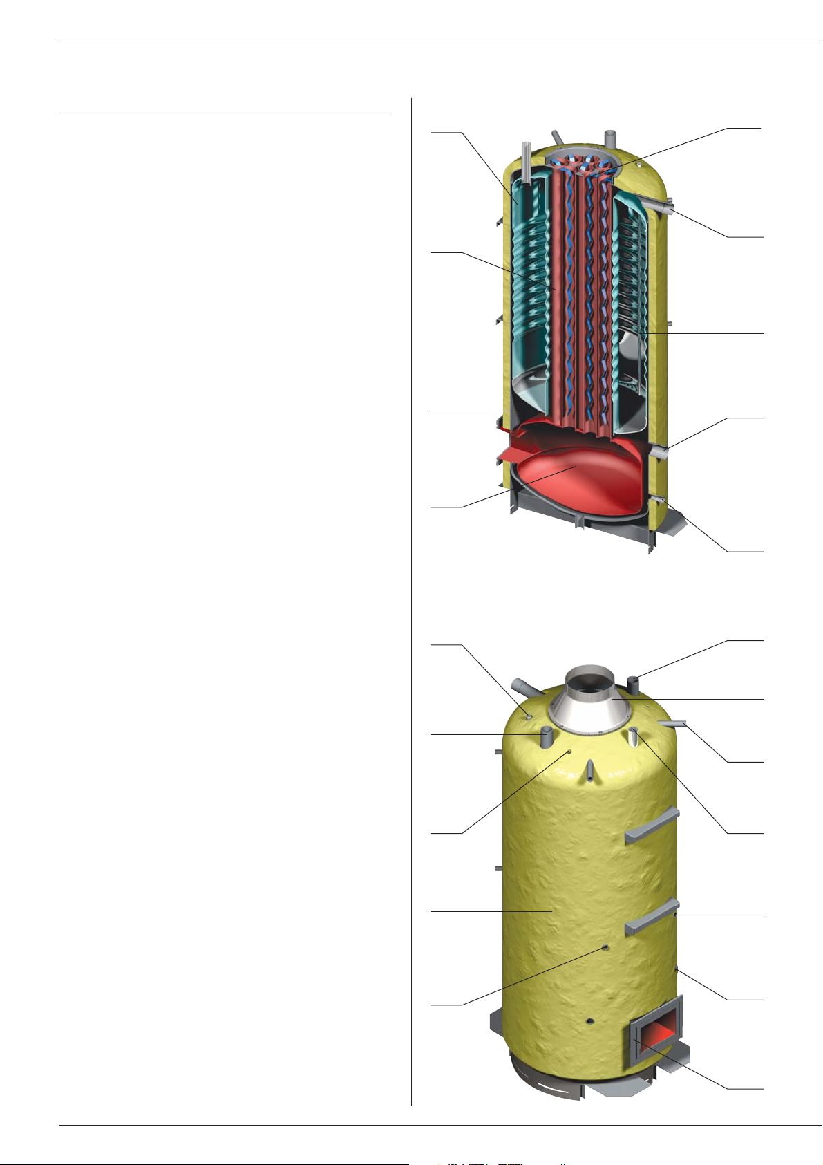
CONSTRUCTION FEATURES
Outer body
The outer body, containing the primary water, is made from STW 22
carbon steel.
TANK-IN-TANK heat exchanger
The ring-shaped inner tank with its large heating surface for
producing domestic hot water is built of Chrome/Nickel 18/10
stainless steel. It is corrugated over its full height by an exclusive
production process and entirely argon arc welded by the TIG
(Tungsten Inert Gas) method.
Combustion gas circuit
The combustion gas circuit is paint-protected and comprises:
• Flue pipes
Depending on output, HeatMaster®200 models contain
several steel flue pipes with an internal diameter of 64 mm.
Each pipe is fitted with a baffle of special steel designed to
improve heat exchange and reduce flue gas temperature.
• Combustion chamber
The combustion chamber on HeatMaster®models is entirely
water cooled.
Insulation
The boiler body is fully insulated by rigid polyurethane foam with a
high thermal insulation coefficient, sprayed on without the use of
CFCs.
Casing
The boiler is covered by a steel jacket which has been scoured and
phosphated before being stove enamelled at 220°C.
Burner
The HM 200 F model is always delivered with a “RIELLO” RG4S 396
T1 fuel oil burner.
Legend
1. “Tank-in-Tank” type storage exchanger
2. Flue ways
3. Primary circuit
4. Combustion chamber
5. Turbulators
6. Heating outlet
7. Stainless steel pocket
8. Heating return
9. Boiler drain cock
10. Hot water priority thermostat bulb
11. Cold water inlet
12. Bulbs of the thermal reset high-limit 95°C thermostat and the
manual reset high-limit 103°C thermostat
13. Insulation
14. Low-water-level pressure switch
15. Hot water outlet
16. Chimney reducer
17. Steam trap
18. T&P valve
(optional)
19. Thermostat-pressure gauge bulb
20. 60 - 90°C control thermostat bulb
21. Flange of the burner chamber plate
Page 7

5
TECHNICAL SPECIFICATION
EFFECTIVE DIMENSIONS
The appliances delivered are factory-tested. Upon receipt, remove the packing and check that there is no damage to the appliances. Refer to the
dimensions and weights listed below for transport purposes.
The jacket is fitted by the installer on site
(see the assembly instructions in the wooden protective casing)
.
HM 200 N HM 200 F
Fuel type Fuel / Gas Fuel
Input kW 154.0 196.0
Output kW 141.7 180.3
Maintenance loss of nominal value at 60°C % 0.43 0.34
Total capacity L 641 641
Primary circuit capacity L 241 241
Hot water connection Ø 2” 2”
Heating connection Ø 2” 2”
Chimney connection Ø mm 250 250
Water tank heat transfer surface m
2
5.30 5.30
Drained weight Kg 530 550
Pressure loss of the primary circuit mbar 240 240
Combustion efficiency % 93.5 93.7
Output CO2 % 12.8 12.9
Net temperature of the flue gases °C 143 140.5
Mass flow rate of combustion products g/sec. 65.2 83.0
Nozzle
(Fuel oil)
gal/h 3.25 / 60° B 4.00 / 60° B
Pump pressure
(Fuel oil)
bar 11.0 11.6
A mm B mm C mm D mm E mm F mm G mm H mm
HeatMaster®200 N 2085 - 1020 - 1020 600 1383 590
HeatMaster®200 F 2085 190 1020 1210 1020 600 1383 590
GENERAL CHARACTERISTICS
(*) The HeatMaster®200F outputs can only be reached if the boiler is fitted with a “RIELLO” RG4S 396 T1 fuel oil burner.
F
338
G
506
A
D
302
C
250
B
H
E
250
190
Page 8

6
TECHNICAL SPECIFICATION
MAXIMUM OPERATING CONDITIONS
Maximum service pressure
(tank full of water)
- Primary circuit: 3 bar
- Secondary circuit: 10 bar
Test pressure
(tank full of water)
- Primary circuit: 4.5 bar
- Secondary circuit: 13 bar
Operating temperature
- Maximum temperature: 90°C
Water quality
• Chlorures: < 150 mg/l (304)
< 2000 mg/l (Duplex)
• 6 ≤ ph ≤ 8
BURNER CHAMBER PLATE
The burner chamber plate secures the burner with 4 screw threads
(M 8). It is thermally insulated to protect it from the heat.
HM 200 N HM 200 F
Peak delivery at 40°C L/10’ 1570 1675
Peak delivery at 45°C L/10’ 1350 1444
Peak delivery at 60°C L/10’ 915 961
Peak delivery at 70°C L/10’ 737 755
Peak delivery at 80°C L/10’ 586 586
Peak delivery at 40°C L/60’ 4920 5976
Peak delivery at 45°C L/60’ 4221 5131
Peak delivery at 60°C L/60’ 2925 3126
Peak delivery at 70°C L/60’ 2412 2309
Peak delivery at 80°C L/60’ 1712 1712
Continuous delivery at 40°C L/h 4020 5161
Continuous delivery at 45°C L/h’ 3446 4424
Continuous delivery at 60°C L/h’ 2412 2598
Continuous delivery at 70°C L/h’ 2010 1864
Continuous delivery at 80°C L/h’ 1352 1352
N.B.:
The outputs above are given for a hot water temperature of 90°C and a cold water temperature of 10°C.
DOMESTIC HOT WATER PERFORMANCES
4 x M8
Ø 22
Ø 4
6
70
1
Ø
Ø
130
45°
Page 9

7
INSTALLATION
BOILER ROOM
Important
• Keep vents free at all times.
• Do not store inflammable products in the boiler room.
• Do not store corrosive products near the boiler, such as paints,
solvents, chlorine, salt, soap and other cleaning products.
• If you smell gas, do not switch on the light or light a flame.Turn off
the mains gas tap at the meter and inform the appropriate
services immediately.
Access
The boiler room must be large enough to allow good access to the
boiler. The following minimum distances are required around the
boiler:
- front 500 mm
- side 100 mm
- behind 150 mm
- above 350 mm
Ventilation
The boiler room must have both low- and high-level ventilation,
in accordance with the local standards and provisions force.
The table below gives an example conforming to the Belgian standards.
Other countries should refer to their own standards.
Base
The base on which the boiler rests must be made of non-combustible
materials.
CHIMNEY CONNECTIONS
IMPORTANT
Boilers must be installed by an approved heating
engineer, in accordance with the prevailing local
standards and regulations.
The duct size may not be smaller than the boiler outlet
duct.
Typical boiler connection: B23
The boiler is connected to the chimney by a metal pipe rising at an
angle from the boiler to the chimney.
A flue disconnection piece is required.
This must be easy to remove to give access to the flue pipes when
servicing the boiler.
Ventilation 200 N 200 F
Min. fresh air requirement m3/h 277 353
Bottom dm
2
2.45 2.45
To p dm
2
4.62 5.88
Chimney / minimum flue diameter 200 N 200 F
E = 5 m Ø F min. mm 284 320
E = 10 m Ø F min. mm 250 269
E = 15 m Ø F min. mm 250 250
Note:
Regulations vary from country to country therefore
the table above is intended only as a guide.
Due to the high efficiency of our boilers, the flue gasses
exit at low temperature. Accordingly, there is risk that
the flue gasses could condense, which could damage
the chimney. In order to avoid this risk, it is strongly
recommended that the chimney be lined.
A condensation drain outlet must be fitted close to the
boiler to prevent condensation products from the
chimney running into the boiler.
To avoid condensation water running out of the
terminal, all horizontal flue runs must fall back towards
the boiler.
A. Top vent
B. Bottom vent
C. Draught regulator
D. Inspection window
E. Height of lined chimney
F. Chimney diameter
When connecting the flue-gas outlet to an existing
chimney, do not take into account the pressure drop
on the “flue gas side”.
F
C
B23
E
B
D
A
Page 10

8
INSTALLATION
HOT WATER CONNECTIONS
Pressure reducing valve
If the mains water pressure is greater than 6 bar, a pressure reducing
valve must be fitted.
Expansion relief valve
The tank expansion relief valve must be ACV approved and
calibrated to a maximum of 7 bar. The valve discharge must be
connected to the drain.
Hot water expansion vessel
We recommend installing a hot water expansion vessel.
Hot water circulation
If the tank is situated a long way from the point of use, then installing
a recirculation loop can provide a faster supply of hot water to the
outlets.
Temperature and pressure relief valve
If using the HeatMaster as an unvented hot water unit, in some
countries, a temperature and pressure relief valve must be fitted consult your ACV stockist for assistance.
Example of hot water connection with thermostatic
mixer
1. Stop cock
2. Non-return valve
3. Pressure reducing valve
4. Expansion relief valve
5. Hot water expansion vessel
6. Hot water secondary pump
(it fitted)
7. Thermostatic mixing valve
8. Drawoff tap
9. Drain cock
10. Stop cock for cleaning
11. Temperature relief valve
(UK-only)
DANGER!
As a safety measure, we strongly advise
installing a thermostatic mixer to prevent the
risk of burns
Example of heating + storage connection
Recommended for applications requiring a high peak flow.
Example of series connection
Preferable for high temperature applications with up to three units.
Example of parallel connection
Recommended for applications with a high continuous flow.
DANGER
HOT
I
O
I
O
I
O
I
O
I
O
12
6
2
3
7
4
8
10
11
5
I
O
9
I
O
Page 11

9
INSTALLATION
HEATING CONNECTION
The HeatMaster®has two connections at the rear that can be used
to connect a central heating circuit. Connecting a heating system
may reduce the domestic hot water performance.
Expansion
The HeatMaster®200 models are equipped with 4 8-litre expansion
vessels. These expansion vessels are sized for hot water operation
only. If a heating system is connected to the primary circuit, calculate
the expansion capacity necessary for the total volume of the heating
system.
(Refer to the technical instructions from a relevant manufacturer of
expansion vessels)
.
Example of a single circuit connection
1. 4-way valve
2. Heating pump
3. Non-return valve
4. Isolating valves
5. Safety valve set to 3 bar with pressure gauge
6. Expansion vessel
7. Drain cock
8. Controller
(optional)
9. Surface-mounted sensor
(optional)
WARNING
The pimary safety valve is supplied with a plastic tube
connected to the discharge outlet - this is for test
purposes only and should be removed. The safety
valve should be connected to a drain using a metallic
pipe eg. copper.
BEWARE
In the case of heating at low temperature, the use of
the kit
(code: 10800099)
is required.
FUEL OIL SUPPLY CONNECTION
(If another make of buner is fitted please refer to that manufacturers technical
manual.)
Installation without return
Installation with return
H
max 4m
L1
L1
L1
H
H
max 4m
L (m)
(L = H + L1)
H (m) Ø int. 8 mm Ø int. 10 mm
0.5 10 20
120 40
1.5 40 80
2 60 100
L (m)
(L = H + L1)
H (m) Ø int. 8 mm Ø int. 10 mm
0 35 100
0.5 30 100
1 25 100
1.5 20 90
215 70
28 30
3.5 6 20
8
I
O
5
1
4
9
6
7
423
Page 12

ELECTRICAL CONNECTIONS
Electrical supply
The boiler operates with a 230 V - 50 Hz single phase supply.
A double pole isolator with a 6 amp fuse or a 6 amp circuit breaker
switch to cut the power supply when servicing or repairing the boiler.
Conformity
Boiler installation must comply with the prevailing local standards and
legislation.
Safety
The stainless steel tank must be earthed separately.
The power to the boiler must be switched off before
any work is carried out.
10
INSTALLATION
WIRING DIAGRAM
HeatMaster®wiring diagram legend 200 N / 200 F
1. 230 V power connection plug
2. On/off switch
3. Temperature high limit cutoff indicator
4. Manual reset high limit thermostat
5. Primary circuit low water pressure indicator
6. Low water pressure switch
7. Time clock
8. Summer/winter switch
9. Hot water priority link
10. Burner lockout indicator
11. Room thermostat connection
(option)
12. Central heating pump
13. HeatMaster shunt pump
14. Burner plug connector
15. Water flow switch connection
(option)
16. Thermal reset high limit thermostat 95°C
17. Control thermostat
Electrical connection HeatMaster®200 N / 200 F
Y/Gr
Br
Or
Or
W
W
R
Pk
B
B
W
B
Y
G
Gr
Y/Gr
Br
B
Y
G
Gr
Or
G
G
G
B
B
Or
B
B
Br
B
G
Br
Br
B
Or
Or Br Bk
B
B
B
BkBk
W
Pk
Bk
W
PkW
B. Blue
Bk. Black
Br. Brown
G. Grey
Gr. Green
Or. Orange
Pk. Pink
R. Red
V. Violet
W. White
Y. Ye l l o w
Y/Gr. Yellow / Green
B
Or
G
B
Or
B
B
R
B
R
B
L1 N T1 T2 S3 B4
L1 N T1 T2 S3 B4
14
12 13
21
11
9
C
5
4
1 2 3 4 5 6 7 8 9 10 11 12 13 14 15 16 17 18 19 20 21 22 23
8
7
3
21
C
103 °C
12
5
3
6
4
P
15
10
95 °C
12
16
17
C
12
0 - 90 °C
C
I
O
L1 N
L1 N
2
1
Page 13

11
MAINTENANCECOMMISSIONING
4. Open the automatic air vent located on top of the boiler.
Important: You must not excessively tighten the threaded plug to
allow automatic bleeding.
5. After venting the air from the system, bring the pressure up to the
static head plus 0.5 bar: 1.5 bar = 10m and 2 bar = 15 m.
6. Check the electrical connection and the ventilation in the boiler
room.
7. Move the main switch to “ON”.
8. Set the thermostat to the desired temperature.
9. When the burner is on, check that the flue-gas discharge pipes
are completely gas tight.
10. After operating for five minutes, turn off the boiler and drain the
heating circuit again, maintaining a pressure of 1 bar.
11. Turn the appliance back on and check the combustion
(see table
page 5).
AB
SERVICE INTERVALS
ACV recommends that boilers should be serviced at least once a year.
The burner must be serviced and tested by a competent engineer.
In the event of heavy use of the boiler, it may require servicing on a
more regular basis than once a year. In this case, contact ACV for
advice.
SERVICING THE BOILER
1. Set the main switch on the control panel to OFF and cut the
outside power supply.
2. Close the valve supplying gas to the boiler.
Vertical flue-gas outlet reducer
3. Take down and remove the flue lining to release the top of the
boiler.
4. Loosen the nuts and remove the chimney reducer.
5. Take out the turbulators from the flue ways to clean them.
6. Dismantle the chamber plate and remove the burner.
7. Brush the flue ways.
8. Clean the combustion chamber and the burner.
9. Replace the turbulators, the chimney reducer, and the flue lining;
check that the seal on the chimney reducer is in good condition.
Replace the seal if necessary.
Horizontal flue-gas outlet reducer
3. Loosen the nuts and remove the chimney reducer.
5. Take out the turbulators from the flue ways to clean them.
6. Dismantle the chamber plate and remove the boiler.
7. Brush the flue ways.
8. Clean the combustion chamber and the burner.
9. Replace the turbulators, the chimney reducer, and the flue lining;
check that the seal between the chimney reducer and the
chimney is in good condition. Replace the seal if necessary.
SERVICING THE SAFETY DEVICES
- Check that all thermostats and safety devices are working properly.
- Test the safety valves on the central heating and hot water circuits.
SERVICING THE BURNER
- Check that the insulation and the seal on the chamber plate are in
good condition; replace them if necessary.
- Check and clean the burner.
- Check that the safety devices are in good working order.
- Check the combustion
(CO2, CO)
and record the values and any
other comments on page 15 of the service record.
FILLING THE HOT WATER AND HEATING CIRCUITS
IMPORTANT
Hot water tank must be pressurised before the
heating circuit is filled.
1. Close the fill valves for the heating circuit (A and B).
2. Open the stop valve (1) and draw-off tap (8).
Fill the tank with the water from the tap; close the draw-off
tap (8).
3. Fill the primary heating circuit by opening the fill valves
(A and B), taking care not to exceed 1 bar of pressure.
6
12
2
3
7
4
5
8
10
11
I
O
9
Page 14

12
MAINTENANCE MISE EN SÉCURITÉ
DRAINING THE BOILER
Water flowing out of the drain cock may be
extremely hot and could cause severe scalding.
Keep people away from discharges of hot
water.
Draining the heating circuit
1. Put the main switch on the control panel to OFF, cut the outside
power supply and close the gas or fuel supply valve to the boiler.
2. Close the isolating valves (4) or manually set the 4-way valve (1)
to “0”.
3. Connect a flexible tube to the drain cock (7).
Make sure it is properly connected.
4. Open the drain cock and allow the hot water to flow into the
drain.
Drain the hot water circuit
1. Turn OFF the on/off switch on the boiler control panel, isolate
external electrical supply, and turn off the gas or oil supply to the
boiler.
2. Release the pressure in the heating circuit until the pressure
gauge indicates zero bar.
3. Close stop cock (1) and turn off tap (8).
4. Open valve (9) then valve (10).
5. Let the water empty into the drain.
For the tank to be emptied, valve (9) must be situated
at ground level.
DANGER
HOT
PLACING THE BURNER IN SAFETY MODE
When the burner is in safety mode, the safety indicator located on
the burner and the control panel lights up.
The red warning light indicates an operating fault. Wait one minute
before rearming the burner by pressing the button on the burner.
If the burner does not relight, call the service engineer after ensuring
that the fault is not due to a power cut or low oil in the tank.
PLACING THE BOILER IN SAFETY MODE
When the high-limit thermostat indicator light on the control panel
comes on: rearm the manual reset high-limit thermostat.
If the anomaly persists, contact your engineer.
Manual reset high
limit thermostat
Burner
lockout
indicator
Combined temperature
and pressure gauge
Time clock
Control
thermostat
ON / OFF
switch
Primary circuit low
water pressure
indicator
High limit cutoff
indicator
Summer / Winter switch
8
I
O
5
I
O
1
7
4
9
423
6
6
12
2
3
4
5
I
O
8
7
10
11
9
Page 15

13
SPARE PARTS
No. Jackets HeatMaster®200 N / 200 F
A01 Right side 21471415
A02 Left side 21471415
A03 Right side rear corner 21478415
A04 Left side rear corner 21473415
A05 Rear panel 21474415
A06 Right side front corner 21472415
A07 Left front side 21479415
A08 Top front panel 2147A415
A09 Lower front panel 2147B415
A10 Burner cover 2147P415
A11 Rear top cover 21475415
A12 Front top cover 21475416
A13 Half-base 2147S415
A14 Unequipped control panel 21477415
A15 Body and accessories 27300048
A16 Wooden protective casings (full jacket and accessories) 26300046
No. Accessories
B01 Full control panel 24614132
B02 Pressure gauge-thermometer 54441008
B03 Control thermostat (60 - 90°C) 54442045
B04 Optimiser 54452000
B05 ON/OFF switch 54766016
B06 Summer/Winter switch 54766017
B07 Manual reset high-limit thermostat (103°C) 54764006
B08 Thermal reset high-limit thermostat 54322000
B09 Control thermostat (80 - 100°C) 54322000
B10 Indicator light 54766001
B11 Stainless steel pocket, Ø 1/2” / L. 1300mm 39438030
B12 Brass steel pocket, Ø 1/2” / L. 100mm 63438001
B13 PVCC plunger, Ø 50 / L. 1300mm 497B0502
B14 Low-water-level pressure switch 557D3011
B15 Top circulating pump 557A4007
B16 3 bar / Ø 3/4” - 1” safety valve 557A1048
B17 8-l expansion vessel 55301200
B18 Steam trap, Ø 1/2” 557A3001
B19 Drain cock, Ø 3/4” 557A1000
B20 Fill set, Ø 1/2” 55426018
B21 Type A, high-level turbulators 507F2009
B22 Type B, low-level turbulators 507F2010
B23 Chimney reducer 507F3019
B24 Chimney reducer seal, Ø 410 / 376 557A0055
B25 Insulation of the burner chamber plate 51700046
B26 H.D.P.E. handle 49410280
B27 Burner chamber plate 2147P415
B28 Control panel self-adhesive 617G0067
Page 16

14
SERVICE RECORD
Date installed:
% CO2
(max. load)
:
Flue gas T°:
Efficiency:
Fuel oil pressure:
Model:
Serial number:
Heating system pressure setting:
Name and signature:
INSTALLATION DETAILS
Date installed:
% CO2
(max. load)
:
Flue gas T°:
Efficiency:
Fuel oil pressure:
Remarks:
Name and signature:
SERVICE RECORD
Date installed:
% CO2
(max. load)
:
Flue gas T°:
Efficiency:
Fuel oil pressure:
Remarks:
Name and signature:
Date installed:
% CO2
(max. load)
:
Flue gas T°:
Efficiency:
Fuel oil pressure:
Remarks:
Name and signature:
Date installed:
% CO2
(max. load)
:
Flue gas T°:
Efficiency:
Fuel oil pressure:
Remarks:
Name and signature:
Date installed:
% CO2
(max. load)
:
Flue gas T°:
Efficiency:
Fuel oil pressure:
Remarks:
Name and signature:
Page 17

15
SERVICE RECORD
Date installed:
% CO2
(max. load)
:
Flue gas T°:
Efficiency:
Fuel oil pressure:
Remarks:
Name and signature:
Date installed:
% CO2
(max. load)
:
Flue gas T°:
Efficiency:
Fuel oil pressure:
Remarks:
Name and signature:
Date installed:
% CO2
(max. load)
:
Flue gas T°:
Efficiency:
Fuel oil pressure:
Remarks:
Name and signature:
Date installed:
% CO2
(max. load)
:
Flue gas T°:
Efficiency:
Fuel oil pressure:
Remarks:
Name and signature:
Date installed:
% CO2
(max. load)
:
Flue gas T°:
Efficiency:
Fuel oil pressure:
Remarks:
Name and signature:
Date installed:
% CO2
(max. load)
:
Flue gas T°:
Efficiency:
Fuel oil pressure:
Remarks:
Name and signature:
Page 18

16
SERVICE RECORD
Date installed:
% CO2
(max. load)
:
Flue gas T°:
Efficiency:
Fuel oil pressure:
Remarks:
Name and signature:
Date installed:
% CO2
(max. load)
:
Flue gas T°:
Efficiency:
Fuel oil pressure:
Remarks:
Name and signature:
Date installed:
% CO2
(max. load)
:
Flue gas T°:
Efficiency:
Fuel oil pressure:
Remarks:
Name and signature:
Date installed:
% CO2
(max. load)
:
Flue gas T°:
Efficiency:
Fuel oil pressure:
Remarks:
Name and signature:
Date installed:
% CO2
(max. load)
:
Flue gas T°:
Efficiency:
Fuel oil pressure:
Remarks:
Name and signature:
Date installed:
% CO2
(max. load)
:
Flue gas T°:
Efficiency:
Fuel oil pressure:
Remarks:
Name and signature:
Page 19

Page 20

INTERNATIONAL
ACV international n.v
KERKPLEIN, 39
B-1601 RUISBROEK - BELGIUM
TEL.: +32 2 334 82 20
FAX: +32 2 378 16 49
E-MAIL: international.info@acv-world.com
BELGIUM
ACV BELGIUM nv/sa
KERKPLEIN, 39
B-1601 RUISBROEK-BELGIUM
TEL.: +32 2 334 82 40
FAX: +32 2 334 82 59
E-MAIL: belgium.info@acv-world.com
CHILE
ALBIN TROTTER Y ACV LTDA
SAN PABLO 3800
QUINTA NORMAL - SANTIAGO - CHILE
TEL.:+56 2 772 01 69
FAX:+56 2 772 92 62/63
E-MAIL: chile.info@acv-world.com
CZECH REPUBLIC
ACV CR SPOL. s.r.o
NA KRECKU 365
CR-109 04 PRAHA 10 - CZECH REPUBLIC
TEL.:+420 2 720 83 341
FAX:+420 2 720 83 343
E-MAIL: ceskarepublika.info@acv-world.com
DEUTSCHLAND
ACV WÄRMETECHNIK GMBH & CO KG
GEWERBEGEBIET GARTENSTRASSE
D-08132 MÜLSEN OT ST. JACOB - DEUTSCHLAND
TEL.:+49 37601 311 30
FAX:+49 37601 311 31
E-MAIL: deutschland.info@acv-world.com
ESPAÑA
ACV ESPAÑA
C/DE LA TEIXIDORA, 76
POL. IND. LES HORTES
E-08302 MATARÓ - ESPANA
TEL.:+34 93 759 54 51
FAX:+34 93 759 34 98
E-MAIL: spain.info@acv-world.com
FRANCE
ACV FRANCE sa
31, RUE AMPERE - Z.I MI - PLAINE
F-69680 CHASSIEU - FRANCE
TEL.:+33 4 72 47 07 76
FAX:+33 4 72 47 08 72
E-MAIL: france.info@acv-world.com
ITALIA
ACV ITALIA
VIA PANA 92
I-48018 FAENZA (RA) - ITALIA
TEL.:+39 0546 64 61 44
FAX:+39 0546 64 61 50
E-MAIL: italia.info@acv-world.com
NEDERLAND
ACV NEDERLAND bv
POSTBUS 350
NL-2980 AJ RIDDERKERK - NEDERLAND
TEL.:+31 180 42 10 55
FAX:+31 180 41 58 02
E-MAIL: nederland.info@acv-world.com
POLAND
ACV POLSKA sp. z.o.o.
UL.WITOSA 3
87 - 800 WLOCLAWEK - POLAND
TEL.:+48 54 412 56 00
FAX:+48 54 412 56 01
E-MAIL: polska.info@acv-world.com
PORTUGAL
BOILERNOX LDA
RUA OUTEIRO DO POMAR
CASAL DO CEGO, FRACÇÃO C,
PAVILHÃO 3 - MARRAZES
2400-402 LEIRIA - PORTUGAL
TEL.:+351 244 837 239/40
FAX:+351 244 823 758
E-MAIL: boilernox@mail.telepac.pt
RUSSIA
ACV RUSSIA
1/9, MALYI KISELNYI
103031 MOSCOW - RUSSIA
TEL.:+7 095 928 48 02 / +7 095 921 89 79
FAX:+7 095 928 08 77
E-MAIL: russia.info@acv-world.com
SLOVAK REPUBLIC
ACV SLOVAKIA s.r.o.
PLUHOVÁ 49
831 04 BRATISLAVA - SLOVAK REPUBLIC
TEL.:+421 2 444 62 276
FAX:+421 2 444 62 275
E-MAIL: slovakia.info@acv-world.com
SLOVENIA
ACV D.O.O. SLOVENIA
OPEKARNA 22b
1420 TRBOVLJE - SLOVENIA
TEL.:+386 356 32 830
FAX:+ 386 356 32 831
E-MAIL: slovenia.info@acv-world.com
UK
ACV UK Ltd
ST. DAVID’S BUSINESS PARK
DALGETY BAY - FIFE - KY11 9PF
TEL.:+44 1383 82 01 00
FAX:+44 1383 82 01 80
E-MAIL: uk.info@acv-world.com
USA
TRIANGLE TUBE PHASE III
FREEWAY CENTER - 1 TRIANGLE LANE
BLACKWOOD NJ 08012 - USA
TEL.:+1 856 228 8881
FAX:+1 856 228 3584
E-MAIL: sales@triangletube.com
excellence in hot water
www.acv-world.com
ARGENTINA
TECNOPRACTICA
ALFEREZ BOUCHARD 4857
1605 CARAPACHAY - BUENOS AIRES
TEL.: +54 11 47 65 33 35
FAX: +54 11 47 65 43 07
E-MAIL: jchas@tecnopractica.com
AUSTRALIA
HUNT HEATING PTY LTD
10 GARDEN BOULEVARD
3172 VICTORIA - AUSTRALIA
TEL.: +61 3 9558 7077
FAX: +61 3 9558 7027
E-MAIL: enquiries@huntheat.com.au
BRAZIL
SIMETAL INDUSTRIA E COMERCIO
DE FERRAMENTAS LTDA
RUA GERSON ANDREIS 535
95112 - 130 CAXIAS DO SUL - BRAZIL
TEL.: +55 54 227 12 44
FAX: +55 54 227 12 26
E-MAIL: export@simetall.com.br
BULGARIA
PROXIMUS ENGINEERING LTD
7 BIAL KREM STR.
9010 VARNA - BULGARIA
TEL.:+359 52 500 070
FAX:+359 52 301 131
E-MAIL: info@proximus-bg.com
CHINA
BEIJING HUADIAN HT POWER TECHNOLOGY
DEVELOPMENT CO. LTD
ROOM B-912, TOWER B, COFCO PLAZA
N°. 8, JIANGUOMENNEI AVENUE
BEIJING 100005 - PEOPLE’S REPUBLIC OF CHINA
TEL.:+86 10 652 30 363/393 EXT 101
FAX:+86 10 652 27 071
E-MAIL: li.zheng@acv-world.com
SHANGHAI COOLTECH LTD
14/F E. CHINA MERCHANTS PLAZA
N°. 333 CHENGDU ROAD (N)
200041 SHANGHAI - CHINA
TEL.:+86 21 52 98 11 22 - 820
FAX:+86 21 52 98 13 58
E-MAIL: cooltech@cooltech.sh.cn
DENMARK
VARMEHUSET
FRICHSVEJ 40 A
8600 SILKEBORG - DENMARK
TEL.:+45 86 82 63 55
FAX:+45 86 82 65 03
E-MAIL: vh@varmehuset.dk
ESTONIA
TERMOX AS
TAHE 112A
51013 TARTU - ESTONIA
TEL.:+372 736 73 39
FAX:+372 736 73 44
E-MAIL: termox@termox.ee
GREECE
ESTIAS
MARASLI STREET 7
54248 THESSALONIKI - GREECE
TEL.:+30 23 10 31 98 77 / +30 23 10 32 03 58
FAX:+30 23 10 31 97 22
E-MAIL: info@genikithermanseon.gr
ÎLE MAURICE
SOTRATECH
29, RUE MELDRUM
BEAU BASSIN - ÎLE MAURICE
TEL.:+230 46 76 970
FAX:+230 46 76 971
E-MAIL: stech@intnet.mu
LITHUANIA
UAB “GILIUS IR KO”
SAVARNORIU PR. 192
3000 KAUNAS - LITHUANIA
TEL.:+370 37 308 930
FAX:+370 37 308 932
MAROC
CASATHERM
PLACE EL YASSIR
20300 CASABLANCA - MAROC
TEL.:+212 22 40 15 23
FAX:+212 22 24 04 86
NEW ZEALAND
ENERGY PRODUCTS INTERNATIONAL
8/10 BELFAST PLACE
PO BOX 15058 HAMILTON - NEW ZEALAND
TEL.:+64 7 847 27 05
FAX:+64 7 847 42 22
E-MAIL: pmckenzie@tycoint.com
ÖSTERREICH
PROTHERM HEIZUNGSTECHNIK Gmbh
TRAUNUFERSTRASSE 113
4052 ANSFELDEN - ÖSTERREICH
TEL.:+43 7229 804 82
FAX:+43 7229 804 92
E-MAIL: protherm@nextra.at
ROMANIA
SC TRUST EURO THERM SA
D.N PIATRA NEAMT - ROMAN
km 2 C.P 5 O.P 3 jud. Neamt
5600 PIATRA NEAMT - ROMANIA
TEL.:+40 233 20 62 06
FAX:+40 233 20 62 00
E-MAIL: office@eurotherm.ro
TUNISIE
SO.CO.ME CHAUMAX
BOÎTE POSTALE N°44
1002 TUNIS - TUNISIE
TEL.:+216 71 78 15 91
FAX:+216 71 78 87 31
UKRAINE
UKRTEPLOSERVICE LTD
PR. LAGUTENKO 14
83086 DONETSK - UKRAINE
TEL.:+38 062 382 60 47/48
FAX:+38 062 335 16 89
 Loading...