

Page 1
Ref: 121003.EN / Date: 2018-06-18
Warning
Carefully read the instructions of
use before using the ventilator to
familiarise yourself with the function
of the equipment
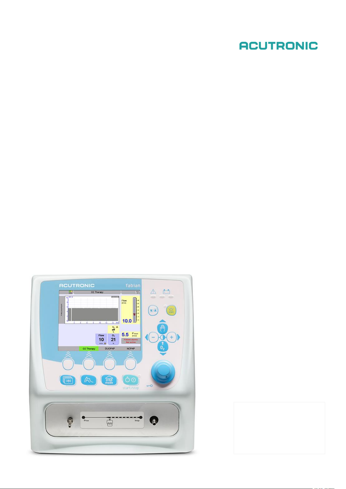
Ventilation Beyond Limits
fabian Therapy evolution
Instructions for use
SW 5.0
Page 2

2 / 72 fabian Therapy evolution | SW 5.0
Ref: 121003.EN / Date: 2018-06-18
DISCLAIMER
ACUTRONIC Medical Systems assumes no responsibility for the use or reliability of its software on
equipment that is not furnished by ACUTRONIC Medical Systems.
ACUTRONIC Medical Systems makes no warranty of any kind with regard to software applications
that are created by the user.
This document contains confidential and proprietary information that is protected by copyright. All
rights are reserved. Any unauthorized copying, storage, reproduction or translation of this
document in any form is strictly prohibited.
Manufactured by:
ACUTRONIC Medical Systems AG
Fabrik im Schiffli
8816 Hirzel / Switzerland
Tel: +41 44 729 70 80
Fax: +41 44 729 70 81
e-mail: info@acutronic-medical.ch
www.acutronic-medical.ch
Page 3

fabian Therapy evolution | SW 5.0 3 / 72
Ref: 121003.EN / Date: 2018-06-18
Table of Contents
1 Working with the instructions ........................................... 6
1.1 Document Structure............................................................................................ 6
1.2 Notices and Warnings ........................................................................................ 6
1.3 Hardware Version Identification ........................................................................ 7
1.4 Symbols ............................................................................................................... 7
2 General Notices ................................................................. 9
2.1 Always Observe .................................................................................................. 9
2.2 Maintenance ...................................................................................................... 11
2.3 Liability for Functionality / Damages .............................................................. 11
2.4 Intended use ...................................................................................................... 11
2.5 Scope of Delivery .............................................................................................. 12
2.6 Contra-indications ............................................................................................ 12
3 System overview .............................................................. 13
3.1 Front Connections ............................................................................................ 13
3.2 Rear Panel .......................................................................................................... 14
4 Operation and Display ..................................................... 16
4.1 Control options ................................................................................................. 16
4.1.1 Buttons ........................................................................................................................................... 17
4.1.2 Rotary pulse knob ........................................................................................................................... 17
4.2 Display concept structure ................................................................................ 18
4.2.1 Display areas .................................................................................................................................. 18
4.2.2 Display screen ................................................................................................................................ 18
4.2.3 Information bar ............................................................................................................................... 19
4.2.4 Numeric field / Alarm limits ............................................................................................................. 20
4.2.5 Graphic field ................................................................................................................................... 20
4.2.6 LED Indicators ................................................................................................................................ 21
4.3 Ventilation Menu ............................................................................................... 22
4.3.1 Operation – General ....................................................................................................................... 22
4.3.2 Operation – Settings ....................................................................................................................... 23
4.3.3 Ventilation parameter dependency ................................................................................................. 24
4.3.4 Locking ventilator parameters ......................................................................................................... 24
4.4 Graphics Menu .................................................................................................. 25
4.4.1 Trend Menu .................................................................................................................................... 26
5 Preparing for Operation ................................................... 27
5.1 Establish Power Supply ................................................................................... 27
5.2 Establish Gas Supply ....................................................................................... 27
5.3 Connect tube set ............................................................................................... 28
5.4 Connect flow sensor in NIV trigger (optional) ............................................... 29
5.5 Switching On the device .................................................................................. 29
5.6 Switching Off the device .................................................................................. 30
6 Device Check .................................................................... 31
7 Configurations Menu ........................................................ 32
Page 4

4 / 72 fabian Therapy evolution | SW 5.0
Ref: 121003.EN / Date: 2018-06-18
7.1 Calibration ......................................................................................................... 34
7.1.1 Calibration Menu at Therapy (only with flow sensor connector) ...................................................... 34
7.1.2 O2 Sensor Calibration ..................................................................................................................... 35
7.1.3 Flow Sensor Calibration .................................................................................................................. 36
7.1.4 SpO2 Module .................................................................................................................................. 36
7.2 Display ............................................................................................................... 37
7.2.1 Touch Screen Settings ................................................................................................................... 38
7.2.2 Trend / Graph Display..................................................................................................................... 38
7.3 Ventilation parameter settings ........................................................................ 39
7.3.1 Standard Hospital Settings ............................................................................................................. 40
7.4 Patient Data ....................................................................................................... 41
7.5 Language ........................................................................................................... 41
7.6 Date / Time ......................................................................................................... 42
7.7 Tools ................................................................................................................... 42
7.8 Info 43
7.9 Service Mode ..................................................................................................... 43
8 Alarm Limits Menu ........................................................... 44
8.1 Automatic Alarm Limits .................................................................................... 46
8.1.1 Alarm Conditions ............................................................................................................................ 46
8.1.2 Automatic Alarm Presets ................................................................................................................ 46
8.2 Alarm Log .......................................................................................................... 47
8.3 Nurse call relay .................................................................................................. 47
9 Battery Operation ............................................................ 48
9.1 Power Failure ..................................................................................................... 49
9.2 Operating on External Power Source ............................................................. 49
10 Function Fields – Ventilation Parameters ......................... 50
11 Ventilation Modes ............................................................ 51
11.1 nCPAP / duoPAP ............................................................................................... 51
11.2 O2 Therapy mode (High and Low flow oxygen therapy) HFNC .................... 52
11.3 Special Functions ............................................................................................. 52
11.3.1 Manual inspiration (man. Breath) .................................................................................................... 52
11.3.2 O2 Flush / Preoxygenation .............................................................................................................. 52
11.3.3 Standby – stopping / pausing mechanical ventilation ...................................................................... 53
12 Error – Cause – Solution – Alarms ..................................... 54
12.1 Application error ............................................................................................... 57
13 Replacing the Oxygen Sensor ........................................... 58
14 Service and Maintenance Intervals .................................. 59
15 Sterilisation / Cleaning / Disinfection ............................... 60
16 Setting Ranges and Parameters ....................................... 61
17 Standard Accessories ....................................................... 62
18 Technical Specifications .................................................. 63
Page 5

fabian Therapy evolution | SW 5.0 5 / 72
Ref: 121003.EN / Date: 2018-06-18
18.1 Ambient Conditions .......................................................................................... 63
18.2 Monitoring .......................................................................................................... 63
18.3 Measuring .......................................................................................................... 64
18.4 Settings in Ventilation Menu ............................................................................ 64
18.5 Dimensions / Weight ......................................................................................... 64
18.6 Ratings ............................................................................................................... 65
18.7 Data storage ...................................................................................................... 66
18.8 Applied Parts ..................................................................................................... 66
18.9 Device Checks ................................................................................................... 66
18.10 Gas blender function ........................................................................................ 67
18.11 Acoustic Energy ................................................................................................ 68
19 Electromagnetic Compatibility Statement ....................... 69
Page 6
6 / 72 fabian Therapy evolution | SW 5.0
Ref: 121003.EN / Date: 2018-06-18
1 Working with the instructions
1.1 Document Structure
The left side of the page …
… displays explanations, instructions and detailed description on the topic or procedure.
The right side of the page …
… displays the graphic representations, operating elements and displays belonging to the
description and guides the user through any handling steps.
These instructions for use describe equipment components and their operation. It is laid out such
that you can step by step become familiar with operation of the ventilator.
Please carefully read the instructions for use before using the ventilator.
Once you are familiar with the basic construction and operation of the ventilator you may use the
instructions for use as a reference.
The table of contents will assist you in quickly locating the respective topic.
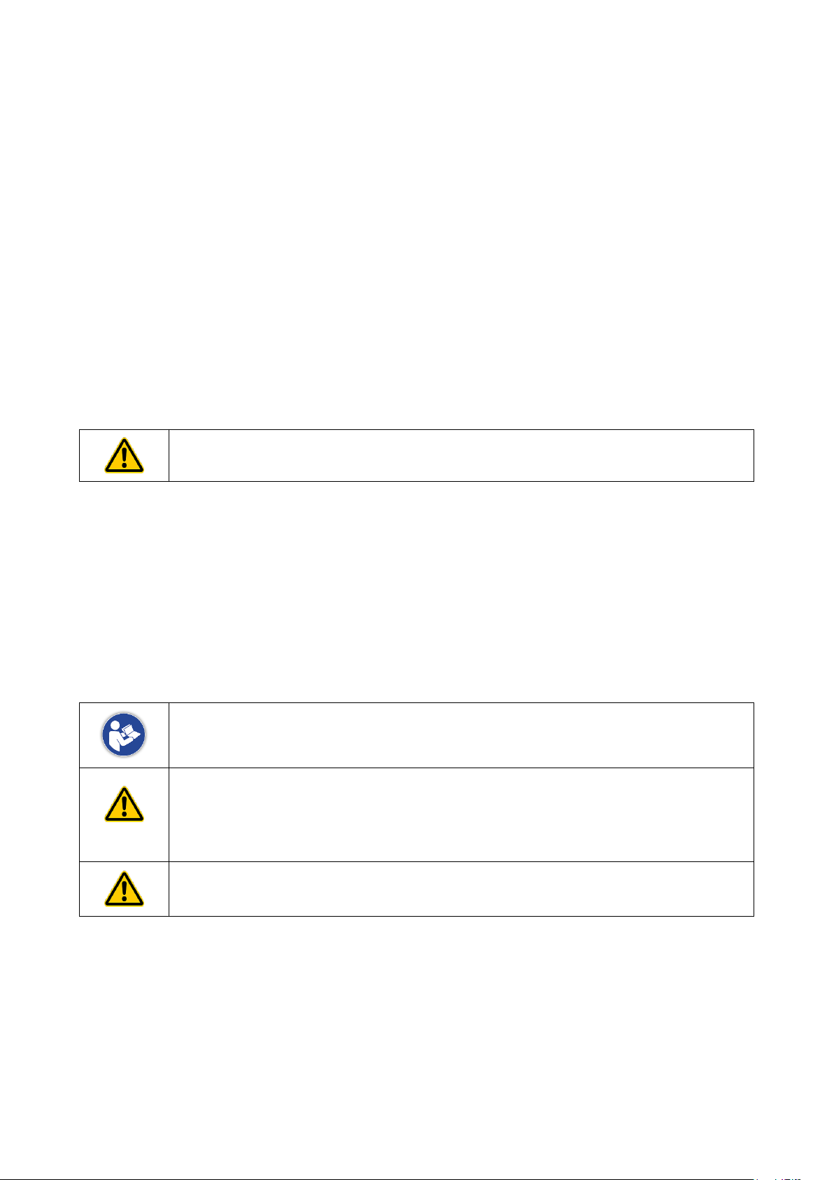
1.2 Notices and Warnings
This document features 3 categories of notices and warnings.
NOTICES are supplements to instructions
Danger
DANGER indicates a not directly imminent but latent hazard which may result in
death or bodily injury unless prevented.
ATTENTION indicates a risk which may result in equipment damage when not
avoided.
Page 7
fabian Therapy evolution | SW 5.0 7 / 72
Ref: 121003.EN / Date: 2018-06-18
1.3 Hardware Version Identification
The hardware version can be identified from the device serial number.
Serial number: xxyyxx-nnnn, yy = Hardware version
From 1st of January 2016 the serial number has been changed to AT-xxxxx
The reason for it is,that the HW revision is only valid when leaving the factory.
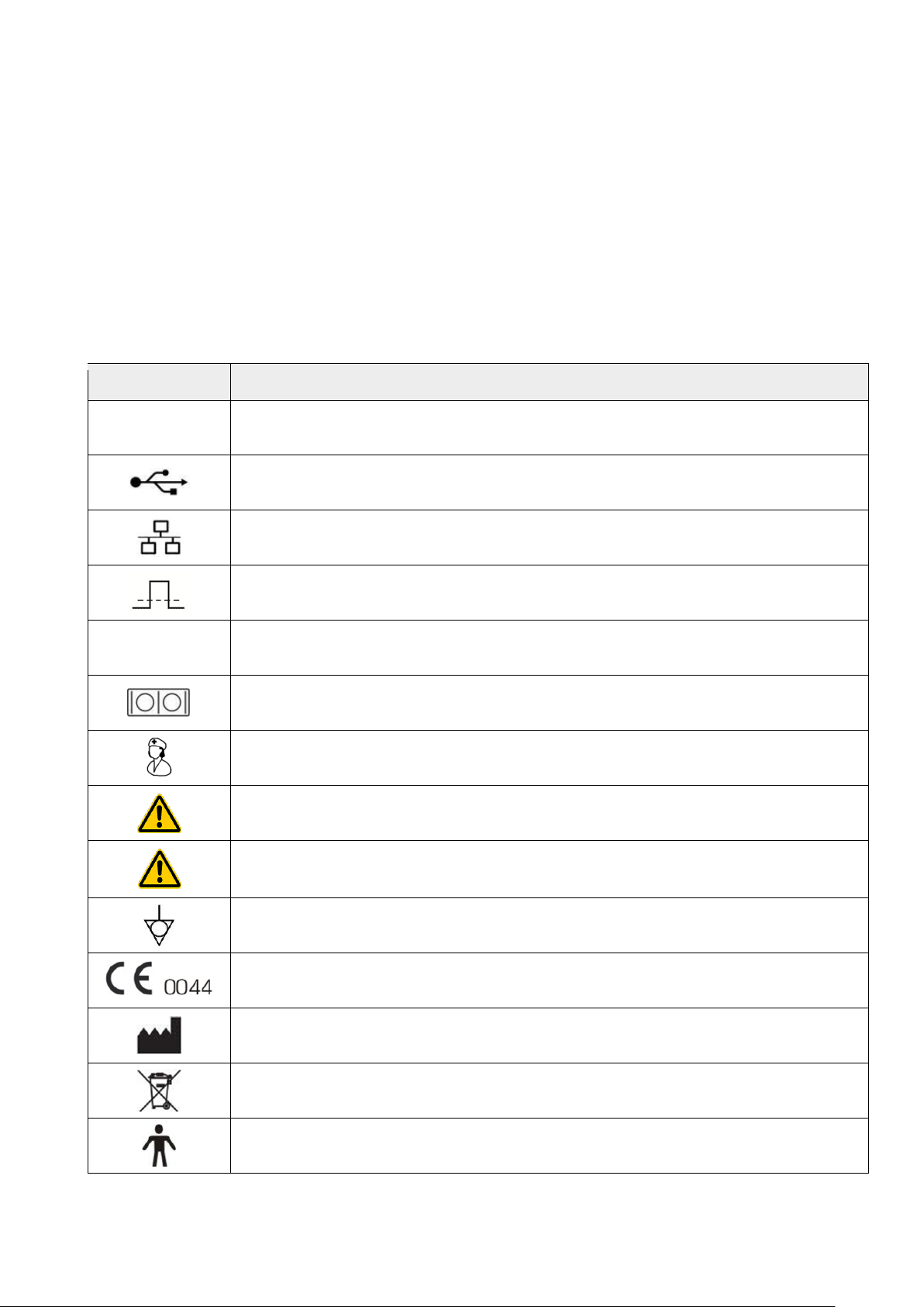
1.4 Symbols
Symbol
Description
VDC 12 – 24V 4A
External power supply input
USB connection
Network connection RJ45
Connection for external trigger
Opt.1
Optional connector
Data input / Data output RS232
Nurse call signal output
Caution, refer to operator’s manual for important safety information / precautions
Flow sensor connection
Potential equalisation connection
Marking per Medical Devices Directive 93/42/EEC
Manufacturer / Date of manufacture
Disposal information
Type B application part
Page 8
8 / 72 fabian Therapy evolution | SW 5.0
Ref: 121003.EN / Date: 2018-06-18
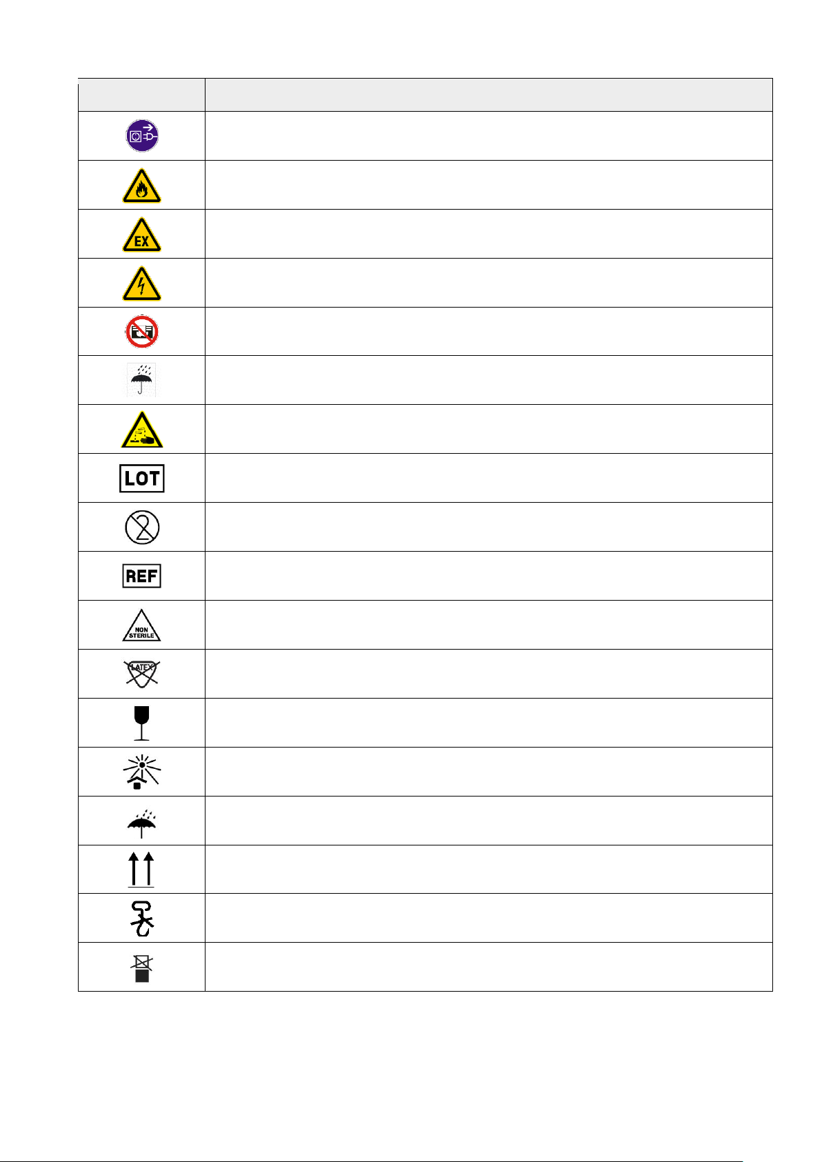
Symbol
Description
Unplug power before opening housing
Flammability warning
Warning regarding operation in explosive areas
Dangerous voltage warning
Do not cover
Protect from moisture
Chemical burn warning
Batch code
Single use
Article No.
Non-sterile
Latex free
Fragile, handle with care
Keep away from heat
Keep dry
This way up
Do not use hooks
Do not stack
Page 9
fabian Therapy evolution | SW 5.0 9 / 72
Ref: 121003.EN / Date: 2018-06-18
2 General Notices
2.1 Always Observe
The use of the ventilator requires detailed knowledge and the observation of this
operator’s manual. This device is only intended for the described use.
Only operate the ventilator with accessories recommended by ACUTRONIC
Medical Systems AG.
The ventilator must be operated by qualified technical staff or staff supervised by
such to ensure immediate remedial action in the event of malfunction.
An alternate ventilation method (e.g. Resuscitator) must be available at all times
when using the ventilator.
If the life-support function is no longer warranted due to a noticeable ventilator
defect, the patient must immediately be artificially ventilated using a stand-alone
ventilator (e.g. Resuscitator).
The ventilator may not be used in combination with inflammable gases or narcotic
agents – there is otherwise an acute risk of fire and explosion!
Never use the ventilator in explosive environments!
An audible signal indicates a system or patient alarm and always requires action
by a medical professional.
Never connect the ventilator to patients if an error or malfunction is detected
during equipment check!
Never connect to electrical devices not mentioned in this operator’s manual
without first consulting the manufacturer or an expert.
Never operate the ventilator while covered or set up in a way so as to negatively
impact the operation or function.
Always unplug before opening the housing!
Never use anti-static or electrically conductive tubes.
Note: the safety and health of the users is guaranteed by the fact that the
products for example do not contain any allergenic or mutagenic materials such
as phthalates.
Page 10
10 / 72 fabian Therapy evolution | SW 5.0
Ref: 121003.EN / Date: 2018-06-18
The device can only be separated from the main power supply by removing the
power cord completely. Please ensure the power socket is freely accessible at all
times for disconnection. Do not remove the power cable unless for service
purposes or transport.
Warning: modification of this equipment is not allowed.
Note: accessories supplied by ACUTRONIC Medical Systems AG for use on
fabian ventilators are biocompatible. Please ensure before applying non-original
accessories that they are biocompatible.
Warning: when connected to a patient do not simultaneously touch the external
power supply and the flow sensor connector cable.
Warning: if the strength of the auditory alarms are less than the ambient sound
this might impede an operator to recognize alarm conditions.
Warning: please ensure that the ventilator is never covered.
Warning: please ensure that the ventilator is never positioned in such a way that
the performance of the ventilator is adversely affected.
Warning: in case of ventilator failure, the lack of immediate access to appropriate
alternative means of ventilation can result in patient death.
Warning: please ensure that alarms are set appropriately prior to use of ventilator
on patient.
Warning: be sure that the gas intake ports are not obstructed
Warning: do not use the fabian in an oxygen-rich environment
Warning: in case portions of the gas pathways through the VENTILATOR can
become contaminated with body fluids or expired gases during NORMAL
CONDITION or SINGLE FAULT CONDITION, please contact ACUTRONIC
Medical Systems.
Warning: only use air and O2 hoses which are in accordance to the ISO 5359
standard
Warning: this VENTILATOR is a high flow device and should only be connected to
a pipeline installation that allows the indicated flow
Warning: this VENTILATOR shall not be used with nitric oxide
Warning: only use this ventilator in combination with an external monitoring (e.g
SpO2) device
Page 11
fabian Therapy evolution | SW 5.0 11 / 72
Ref: 121003.EN / Date: 2018-06-18
2.2 Maintenance
This device is a ventilator classified as Class IIb according to the European directive, as such:
• Inspection as per manufacturer specifications is required every 12 months.
• Maintenance must be performed by ACUTRONIC trained experts with access to
appropriate test and measuring equipment.
We strongly recommend ACUTRONIC Medical Systems AG exclusive representatives for service
agreements and repairs.
Only use original ACUTRONIC parts for repairs.
Note chapter “14. Service and Maintenance Intervals”
Original packaging should be kept for the possible return of the unit. Only original
packaging ensures optimal protection of the equipment during transport. If it is
necessary to return the equipment during the warranty period, the manufacturer is
not liable for damages caused by incorrect packaging.
2.3 Liability for Functionality / Damages
In the event of improper equipment maintenance or repair by any person not associated with
ACUTRONIC Medical Systems AG support or improper use, any and all liability for the functionality
is transferred to the owner or operator.
ACUTRONIC Medical Systems AG assumes no liability for damages caused by the nonobservance of preceding notices. The preceding notices do not extend the warranty and liability
terms of the ACUTRONIC Medical Systems AG sales terms and delivery conditions.
2.4 Intended use
The fabian Therapy evolution is intended for premature infants, new-borns as well as children
weighting up to 30 kg.
The fabian Therapy evolution is intended for “in-patient use” in hospitals, medically-used rooms
and intra-hospital patient transport.
The fabian Therapy evolution is an electronically microprocessor controlled ventilator.
The fabian Therapy evolution ventilates with excess pressure based on the continuous-flow
principle. (Time cycled and pressure limited)
Oxygen is metered by the integrated Air/O2 blender.
The oxygen concentration is measured internally with a galvanic oxygen sensor.
Page 12

12 / 72 fabian Therapy evolution | SW 5.0
Ref: 121003.EN / Date: 2018-06-18
The ventilator is intended for the following, non invasive, ventilation methods:
• O2 Therapy
• NIV ventilation nCPAP/duoPAP with variable flow generators
(Infant Flow®, Infant Flow LP®, InspireTM, Medijet®
The equipment is operated by a physician or at his orders by a professional with technical training
in this task, where up on any user must be trained on this equipment and familiar with the
operator’s manual and the use of the equipment.
The fabian Therapy evolution is not approved for use in a homecare environment.
2.5 Scope of Delivery
This product includes the following items:
• 1 x fabian Therapy evolution ventilator (#121001)
• 2 x Infant flow connecting tube (#1530010.01)
• 1 x Power cable (# country specific)
• 1 x Operating manual (# country specific)
2.6 Contra-indications
No contra-indications for the use of the fabian Therapy evolution neonatal and infant ventilator in
an intensive care unit are known.
In the event of ventilation for more than several hours, care must be taken for optimal conditioning
of the respiratory gases (warmth, moisture) to guarantee secretion mobilization and prevent
damage to mucous membranes.
In general, it should be noted with regard to contra-indications that ventilation of children should
only be carried out by clinically trained specialists who have sufficient knowledge of ventilation at
this age.
Detailed studies and experience can be requested from the following address:
ACUTRONIC Medical Systems AG
Fabrik im Schiffli
8816 Hirzel / Switzerland
Tel: +41 44 729 70 80
Fax: +41 44 729 70 81
Email: info@acutronic-medical.ch
Page 13
fabian Therapy evolution | SW 5.0 13 / 72
Ref: 121003.EN / Date: 2018-06-18
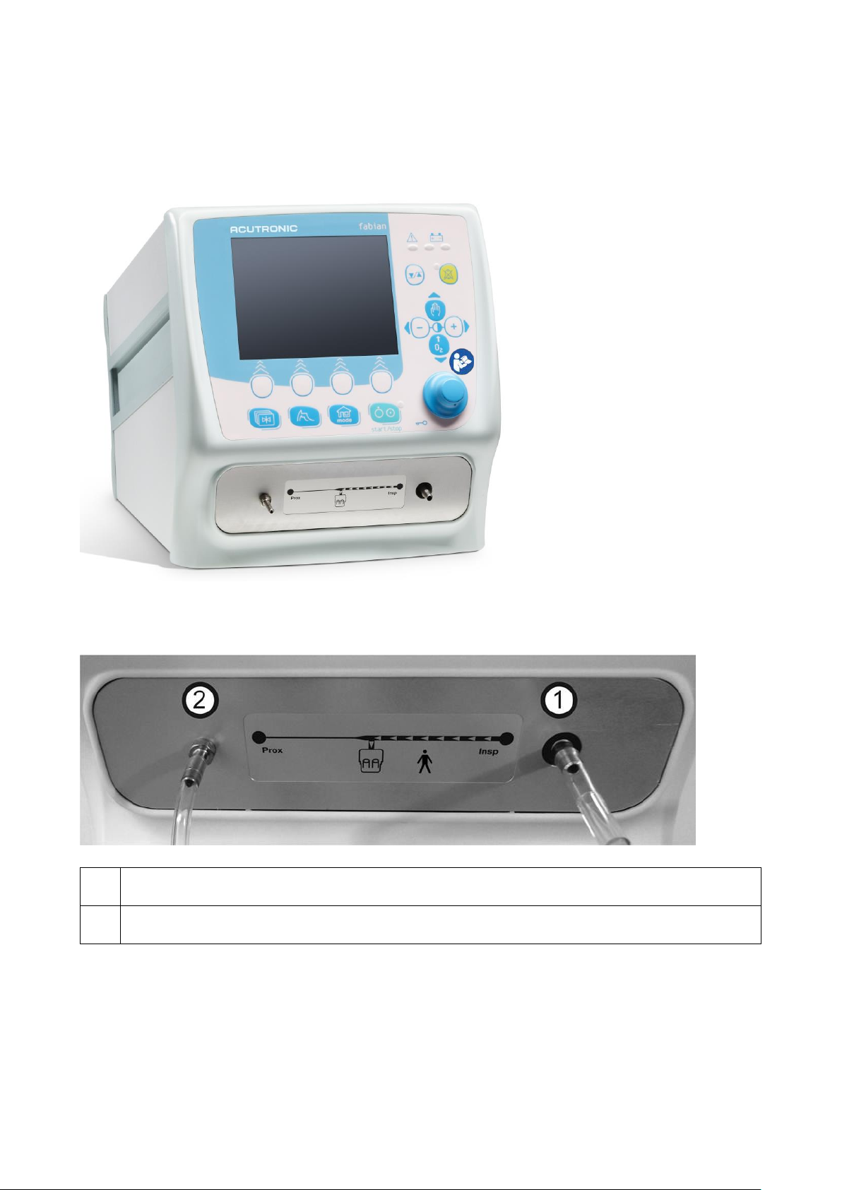
3 System overview
3.1 Front Connections
1
Connection for fresh gas
2
Pressure measuring tube port
Page 14

14 / 72 fabian Therapy evolution | SW 5.0
Ref: 121003.EN / Date: 2018-06-18
3.2 Rear Panel
1
Mains connection with fuse holder
2
Terminal stud for potential equalization
3
Connection for external voltage supply 12 – 24V DC
With HW Rev. 1.0 use only with connection cable Part. No. 151401
4
Nurse call, max. Switching voltage 50 VDC
5
Covered with a faceplate / Flow sensor connector (from SN AT-03001)
6
Network connection for data management
(For connection to network with minimum 3 KV galvanic isolation)
7
USB connection for data output (log file), software update. Connection for Masimo SpO2
module.
8
RS232 interface, service, PDMS
9
Connection for compressed air supply 2.0 – 6.5 bar / 40 l/min
10
Connection for future use, covered with a faceplate
11
Oxygen sensor
12
Connection for future use, covered with a faceplate
13
Connection for oxygen “O2” supply 2.0 – 6.5 bar / 40 l/min
Page 15

fabian Therapy evolution | SW 5.0 15 / 72
Ref: 121003.EN / Date: 2018-06-18
For Adapter to DISS see “17. Standard Accessories”
Warning: Do not connect Ethernet, Nurse call, USB, R232 ports to anything other
than specified devices.
The PIN for the Potential Equalisation is there for additional safety and can be connected to an
equipotential zone. Please adhere to local guidelines when using this PIN. The guidelines may
vary between countries, localities and power companies. Always keep the PIN for Potential
equalisation accessible.
Maximum Connected Loads:
Nurse call: Galvanically isolated relay output.
max Load: 30 V / 1 A DC or AC
USB: 5 V/150 mA
RS232: 3.3 V/100 mA
Page 16
16 / 72 fabian Therapy evolution | SW 5.0
Ref: 121003.EN / Date: 2018-06-18
4 Operation and Display
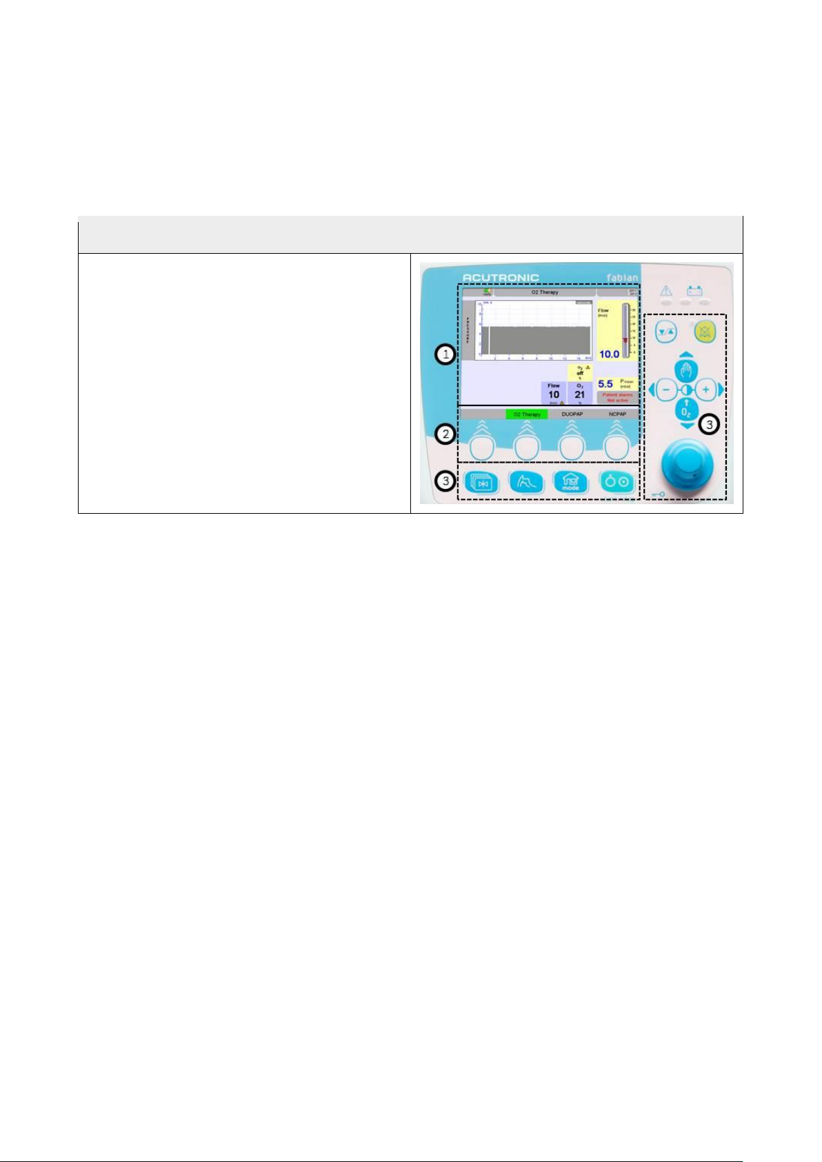
4.1 Control options
The control panel features two key elements:
1. The display (Touch Screen) allows the
direct control of the ventilator parameters
by tapping defined buttons on the graphic
user interface.
2. Fields in the lower section of the touch
screen are operated with the buttons
underneath.
3. The button /-control panel incremental knob
(combined with a push button and selection
dial)
Page 17
fabian Therapy evolution | SW 5.0 17 / 72
Ref: 121003.EN / Date: 2018-06-18
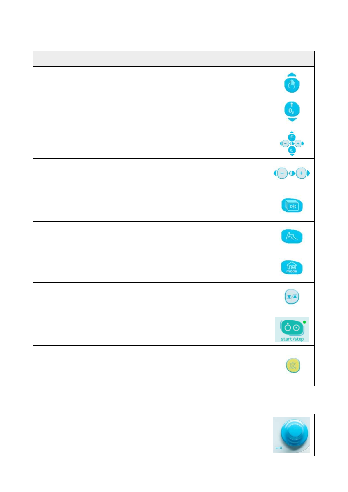
4.1.1 Buttons
The key pad features 2 rows of buttons with various functions.
Manual breathing
Used to apply a manual breath. Available in all the ventilation modes.
O2 Flush
Used to start O2 flush. Flush concentration and time can be preset.
Cursor buttons
These buttons serve as control in several menus.
Screen contrast setting
Used to adjust the brightness of the screen.
Menu / Calibration
Used to access the configuration and calibration menus. Pressing once will open
the calibration menu; pressing again will open the configuration menu.
Waves
Switches to Waves display and values are shown in big letters.
Home
Displays the main screen for selecting the respiration mode.
Alarm limits
Switches to the alarm limits configuration.
On / off – start / stop
For switching the device on and off, stopping and resuming ventilation.
Alarm Mute
For acknowledging and muting alarms for a maximum duration of 120 seconds.
Subsequent alarms with higher priority are only displayed optically during
muting.
4.1.2 Rotary pulse knob
The rotary pulse knob combines a push button with a rotary knob for executing
various settings, selections and confirmation options.
Page 18
18 / 72 fabian Therapy evolution | SW 5.0
Ref: 121003.EN / Date: 2018-06-18
4.2 Display concept structure
4.2.1 Display areas
The information system features 2 key display areas:
1. The touch screen
2. LED indicators
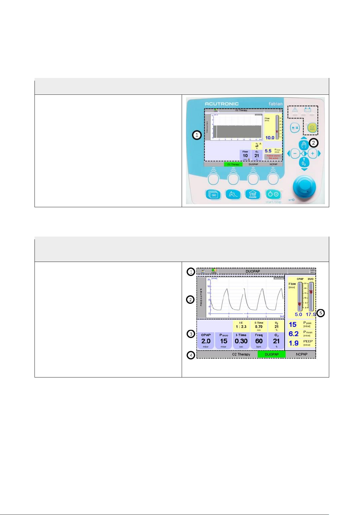
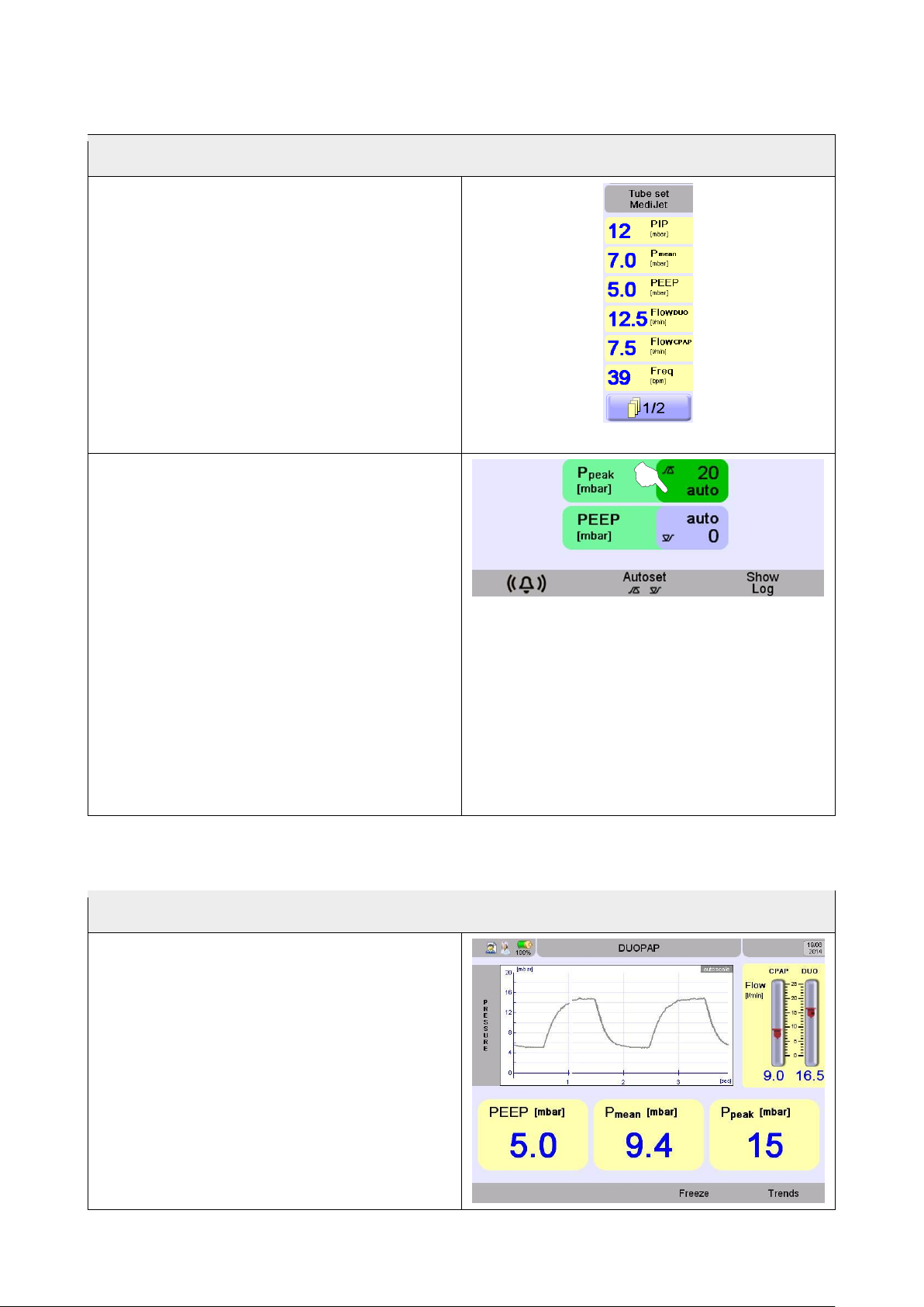
4.2.2 Display screen
The display screen shows various information, setting and display fields depending on the
display settings or menu:
1. Info bar indicating battery status, time/date,
status information, system and alarm
information and ventilation mode
2. Pressure graph
3. Parameter setting field
4. Selection or display of operating mode
5. Numeric field / alarm limits
Depending on the display mode selected,
individual fields may be shown/hidden.
Display field options will be described later.
1
1
5
Page 19
fabian Therapy evolution | SW 5.0 19 / 72
Ref: 121003.EN / Date: 2018-06-18
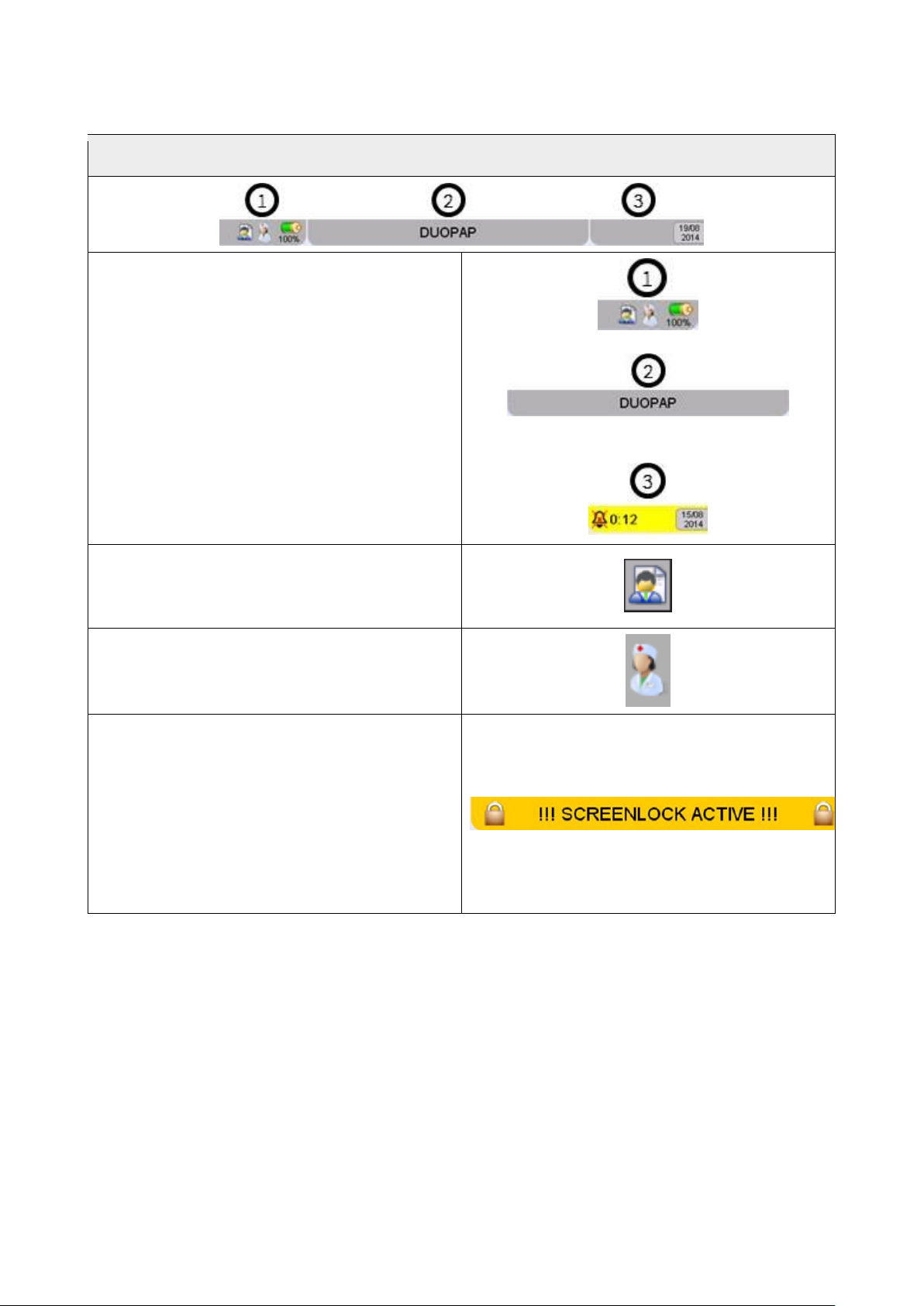
4.2.3 Information bar
The Info bar displays from general information to displaying alarms. It is divided into 3 sections.
The Info bar indicates the following among
other things:
1. Patient data available
Nurse call active / inactive
Battery charge status
2. Ventilation mode, info and alarm display
3. Alarm Mute (time remaining until alarm
reactivates)
Time / date
The patient symbol indicates patient data
associated with the current ventilator operation
is saved to the device.
The nurse indicates Nurse Call is activated
Ventilation mode / Info / and Alarm display
Displays ventilation mode and, if applicable,
additional current information and notices. A
red blinking info bar also alerts the user to
active alarms.
If screen lock is in use, the symbol for locked
screen is displayed.
Page 20
20 / 72 fabian Therapy evolution | SW 5.0
Ref: 121003.EN / Date: 2018-06-18
4.2.4 Numeric field / Alarm limits
The numeric field are showing all measured values
In the numeric field the selected ventilation
mode related measured values are displayed.
There can be multiple pages of numeric fields.
To go to the next page, press the button
underneath the numeric field.
Depending on the ventilation mode the data is
updated as average/minute or by breath.
Numeric field
The upper and lower limits can be manually or
automatically adjusted in the alarm limits
menu.
To adjust the alarm limit manually:
• press the alarm limits button
• touch the parameter you wish to change
• the button turns from dark blue to green
• with rotary pulse knob, change the value
• to confirm the setting, either touch
parameter button again, or push rotary
pulse knob again.
To automatically set the alarm limits, select
parameter and touch AUTOSET button.
Alarm limits
4.2.5 Graphic field
The button Waves enlarges the measured values
Displays the current values in big letters and
also the actual Wave
Page 21
fabian Therapy evolution | SW 5.0 21 / 72
Ref: 121003.EN / Date: 2018-06-18
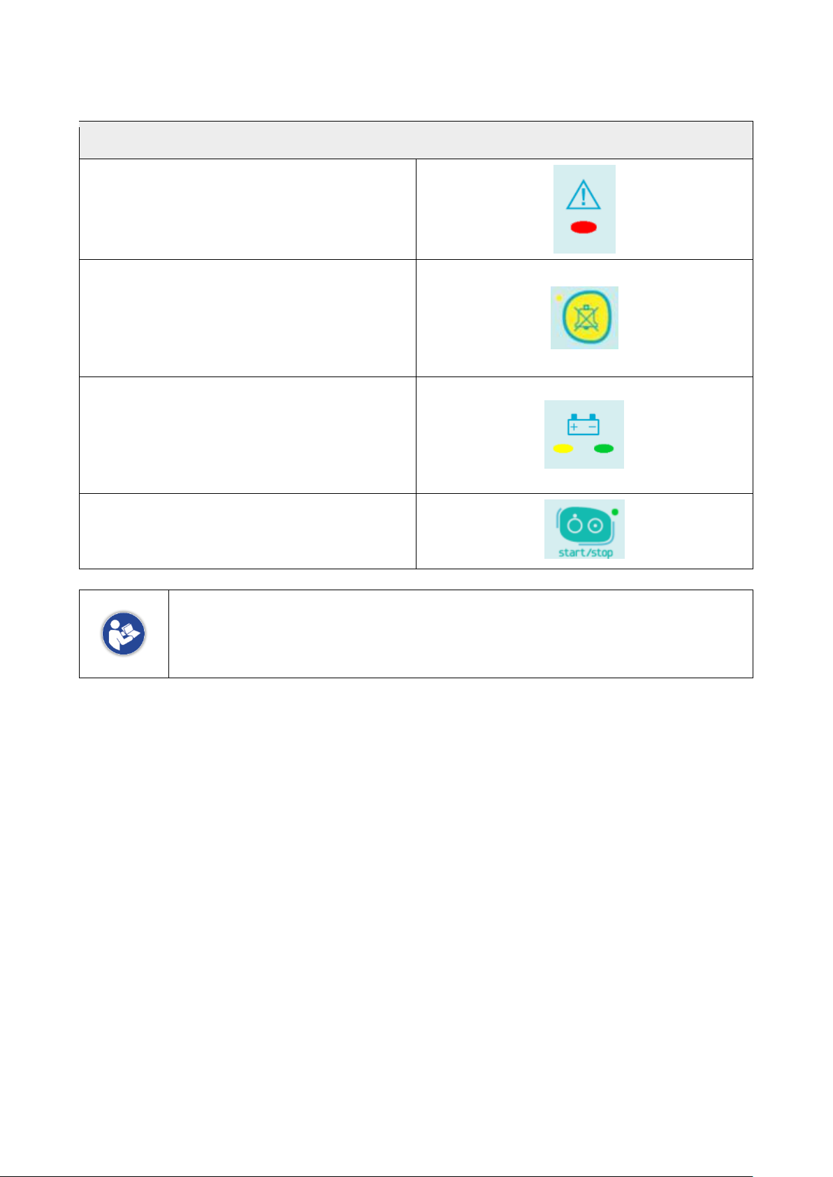
4.2.6 LED Indicators
LED Indicator explanation
Warning LED
This LED will light or blink red when a system
alarm is triggered.
LED Alarm Mute
This LED lights up in yellow when the alarm is
muted.
The remaining time for the alarm muting is
displayed on the screen.
Battery LED
This LED will light yellow in battery operation
and green when the battery is fully charged.
The LED will blink green when the battery is
charging.
Mains LED
This LED will light green in mains operation,
and will switch off in battery operation.
During voltage supply via the external 12 - 24 VDC connection the mains LED are
not illuminated.
Battery LED flashes in green when the battery is being charged.
Page 22
22 / 72 fabian Therapy evolution | SW 5.0
Ref: 121003.EN / Date: 2018-06-18
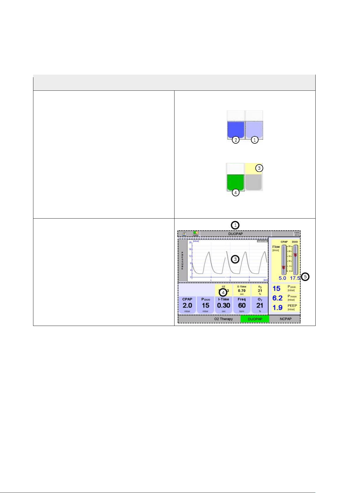
4.3 Ventilation Menu
4.3.1 Operation – General
Push buttons and their statuses are indicated
by various colours:
1 light blue: Push button
2 dark blue: focused push button
3 yellow (in functions menu): parameters
metered
4 green: selected push button, if the push
button features a parameter for setting a
value it may now be changed.
Depending on the ventilation mode, the
respiration menu indicates the configuration
parameters (4) and measurements (5) relevant
in this mode.
The Info bar (1) indicates current information.
The ventilation parameters may be changed in
the menu (5).
Page 23

fabian Therapy evolution | SW 5.0 23 / 72
Ref: 121003.EN / Date: 2018-06-18
4.3.2 Operation – Settings
Settings
The ventilation parameters may be set before
starting/activating ventilation mode:
1 Tap 1x the desired ventilation mode pre-
setting is activated
2 The configuration parameters for the
preselected ventilation mode may now be
adjusted
3 Tap ventilation mode again: key will turn
green, ventilation will start with the defined
parameter settings. The selected parameter
may also be confirmed by pressing the
rotary knob.
If the setting is active (yellow button) and no
action is taken for 15 seconds, or the
preselected mode is not confirmed by tapping
again, the device will continue in the previous
mode, new pre-settings are deleted.
After confirming a preselected parameter the audible alarm is automatically
suppressed for 15 seconds.
The audible alarm may be immediately activated by pressing the Alarm Mute
button.
Press any blank area or another parameter to not accept the parameter and keep
the previous value
Old active alarms at the time the mode is switched will automatically be reset.
Page 24

24 / 72 fabian Therapy evolution | SW 5.0
Ref: 121003.EN / Date: 2018-06-18
4.3.3 Ventilation parameter dependency
If parameters are mutually regulating, an arrow
will appear on the parameter that needs to be
modified. The arrow shows in which direction
the modification has to be done.
List of dependencies:
• O2 Flush min. 2 Vol% above O2 setting, max. 100 Vol%
• P
DUO
min 2 mbar over PEEP
• Pmanuell min 2 mbar over CPAP
• Rise-time ≤ I-Time
4.3.4 Locking ventilator parameters
Some ventilator parameters are “locked”
to prevent unusual high values.
When this value is reached a key symbol
will appear and a notice signal will sound.
The high value must be confirmed by pressing
the rotary knob again. (see table below)
List of locked values
Parameter
Locking at
Modes
I-Time
I : E > 1
DUOPAP
Frequenz
I : E > 1
DUOPAP
Flow
> 5 l/min
O2 Therapy
CPAP
> 10 mbar
DUOPAP / NCPAP
Page 25

fabian Therapy evolution | SW 5.0 25 / 72
Ref: 121003.EN / Date: 2018-06-18
4.4 Graphics Menu
The graphics menu may be accessed via the waves key on the keypad.
The graphics menu
Displays the current values in big letters and
shows also the pressure wave.
Use “waves” to access the big screen
menu.
The button underneath “Freeze” stops waves
being updated. The key will turn green.
The measured parameters in the display field
continue being updated.
Press the key again to continue updating the
Waves data.
Page 26

26 / 72 fabian Therapy evolution | SW 5.0
Ref: 121003.EN / Date: 2018-06-18
4.4.1 Trend Menu
The device trend function automatically saves an average of measurements every 30 seconds.
Measurements of up to 5 days can be recorded.
Trend data is automatically deleted in the following cases:
• Date and / or time is modified
• New patient data is entered
• Software update
A confirmation message will always be displayed before trend data is deleted.
1. Parameter selection for graphic waves
2. Graphics
3. Parameter values
4. Timeline
5. Adjust timeline (max. 5 days – min. 30 minutes)
6. Update data (refresh)
1
Page 27

fabian Therapy evolution | SW 5.0 27 / 72
Ref: 121003.EN / Date: 2018-06-18
5 Preparing for Operation
5.1 Establish Power Supply
Connect the device with power cable to a suitable power socket.
Do not connect the device to a power outlet strip.
Exception: the power outlet strip has been expressly approved by the manufacturer for connection
to a ventilator.
The device can be operated with 100 VAC to 240 VAC and automatically adjusts to particular
voltage without manual switch-over being necessary.
The used fuses must correspond with the value and type approved for the fabian.
The particular fuse type and value is printed on the back of the fabian.
Replacement of the fuses may only be carried out by trained staff. Please replace
fuses with identical values, failing to do so, might cause fire hazards.
WARNING: To avoid risk of electric shock, this equipment must only be connected
to a mains supply with protective earth.
5.2 Establish Gas Supply
Connect the compressed air and oxygen supply tube to the central gas supply.
If there is no central gas supply, gas supply from cylinders is also possible.
The inputs are coded to prevent wrong connection.
Input pressure 2 – 6.5 bar for Oxygen and Medical grade AIR (dust-free, oil-free and dry).
Page 28

28 / 72 fabian Therapy evolution | SW 5.0
Ref: 121003.EN / Date: 2018-06-18
5.3 Connect tube set
Never use anti-static or electrically conductive tubes.
The pressure gradient on the ventilation system of the ventilator measured on the
patient connection port may increase when accessories or other components are
attached to the ventilation system.
Preparing the nCPAP tubing system
• Connect nCPAP adapter to the fabian
nCPAP port. (1)
• Connect 22 mm adapter connector to
humidifier chamber.
• Connect nCPAP system pressure
measuring tube to fabian port marked
prox. (2)
• Connect nCPAP system to humidifier
chamber.
• Apply nCPAP system to patient per
manufacturer specifications.
For details of using nCPAP systems, refer to the operators manual of the supplier of the
consumables.
Page 29

fabian Therapy evolution | SW 5.0 29 / 72
Ref: 121003.EN / Date: 2018-06-18
5.4 Connect flow sensor in NIV trigger (optional)
Preparing the nCPAP
InfantFlow/InfantFlowLP/Inspire tubing system
• Connect flow sensor with an adapter to
exhalation tube as shown in the picture
Recommendation:
• Please use the exhalation tube as short as
possible
5.5 Switching On the device
Use the ON / OFF button on fabian Therapy
evolution to switch on the device.
When the device is powered on the start-up
screen will appear and the equipment will
perform a self-test.
The SOFTWARE REVISION, the CHECK
SUMS and the status of the interfaces will be
checked.
(ok ≙ no error)
The O2 will be automatically calibrated after
start up. After that every 24 hours.
Can be also done manually after opening O2
sensor menu.
All audible alarms are silenced for 2 Minutes
after startup of fabian.
Page 30

30 / 72 fabian Therapy evolution | SW 5.0
Ref: 121003.EN / Date: 2018-06-18
5.6 Switching Off the device
Disconnect patient.
Use the start/stop button on fabian Therapy
evolution to switch off the device.
Hold start/stop button until the equipment is
switched off.
Once the device has powered off a notice tone
will sound.
Press the “Alarm Mute” button to confirm
system switch off.
Hold the button for at least 3 seconds until the
WARNING LED stops.
Page 31

fabian Therapy evolution | SW 5.0 31 / 72
Ref: 121003.EN / Date: 2018-06-18
6 Device Check
Always perform an equipment check before each ventilator use!
What
How
Target
Gas supply
Attach high pressure air and oxygen
supply hoses on the rear side of the
ventilator. Connect with
corresponding wall outlets
Air and oxygen supply hoses are
correctly connected
Breathing
system
Tubes
Water traps (if needed)
Respiratory Humidifier and tube
heating
Patient circuit assembled correctly as
per manufacturer’s instructions
Switch on test
Switch on fabian
Alarm tone (loudspeaker)
Self-test successful
Alarm tone audible during switch-on
test. (2 beeps)
Calibration
O2 sensor automatic calibration
Calibration successful
Leakage test
Start nCPAP mode
CPAP 5 mbar
P manual 15 mbar
Press button manual insp.
Pressure of 15 ± 2 mbar is achieved
Disconnection
alarm
Disconnect patient supply line from
the device
Reconnect the tube.
Warning: disconnected will appear
after the set delay.
Battery
Unplug power cord
Reconnect power cord
fabian will automatically switch to
battery mode
Page 32

32 / 72 fabian Therapy evolution | SW 5.0
Ref: 121003.EN / Date: 2018-06-18
7 Configurations Menu
The configuration menu can be accessed by pressing the Menu / Calibration key on the
keypad. Depending on the HW state of the device the configuration menu can contain the sensor
related submenus too.
Configuration menu in Therapy with flow sensor connector
1. Calibration menu
2. Display
3. Ventilation
4. Patient Data
5. Language
6. Date / Time
7. Tools
8. Info (System Information)
9. PDMS network settings
10. Service Mode
1 2 3
4
5 6 7 8 9
10
Page 33

fabian Therapy evolution | SW 5.0 33 / 72
Ref: 121003.EN / Date: 2018-06-18
Configuration menu in Therapy without flow sensor connector
1. Calibration O2
2. Display
3. Ventilation
4. Patient Data
5. Language
6. Date / Time
7. Tools
8. Info (System Information)
9. PDMS network settings
10. SpO2 sensor
11. Service Mode
1 2 3 4 5 6 7 8 9
11
10
Page 34

34 / 72 fabian Therapy evolution | SW 5.0
Ref: 121003.EN / Date: 2018-06-18
7.1 Calibration
7.1.1 Calibration Menu at Therapy (only with flow sensor connector)
Page 35

fabian Therapy evolution | SW 5.0 35 / 72
Ref: 121003.EN / Date: 2018-06-18
7.1.2 O2 Sensor Calibration
Or access the calibration menu directly via the button “Menu / Calibration”:
The O2 sensor is automatically calibrated when the device starts up and every 24
hours when in use.
During calibration procedure, the FiO2 concentration of the fresh gas to patient is
not altered.
In case of a supply gas failure, oxygen sensor calibration is disabled automatically
to avoid false sensor calibration
Manual calibration:
Press 21% O2 (or 21+100% O2) key.
Calibration procedure starts and if successful,
indicated with the green tick
Either a one point or two point calibration can
be performed.
After a successful calibration, the date of the last calibration will be displayed in the corresponding
field.
Automatic sensor calibration runs every time the equipment restarts and every 24h.
The gas concentration to patient however is not altered during this calibration
procedure.
Page 36

36 / 72 fabian Therapy evolution | SW 5.0
Ref: 121003.EN / Date: 2018-06-18
7.1.3 Flow Sensor Calibration
Or access the calibration menu directly via the calibration key:
Ensure no gas will flow through the flow sensor
during calibration.
To do so the sensor may be held occluding
either one or both ends with a sterile glove.
Press “Flow Cal” button
First Checking will appear, then Calibration
running.
Following successful calibration, the date of the last calibration will be displayed in the
corresponding field.
The flow sensor calibration needs to be performed each time a new sensor is put in
place.
Sensor calibration remains valid, even if unit is switched off and after restart of it.
We recommend cleaning flow sensor once per day.
Flow sensor calibration is available only with InfantFlow and InfantFlow LP
generator selected and in ventilation mode NCPAP and DUOPAP.
7.1.4 SpO2 Module
For more information on the SpO2 configurations please refer to the separate
available manuals.
Page 37

fabian Therapy evolution | SW 5.0 37 / 72
Ref: 121003.EN / Date: 2018-06-18
For the usage of SpO2 modules from Masimo, please notice:
NO IMPLIED LICENSE: Possession or purchase of this device does not convey
any express or implied license to use the device with replacement parts which
would, alone or in combination with this device, fall within the scope of one or more
of the patents relating to this device.
PATENT MARKING: This device is covered under one or more of patents as set
forth at: http://www.masimo.com/patents.htm
7.2 Display
1. Lock touchscreen. The screen will automatically be unlocked if an alarm is triggered or the rotary
knob is pressed.
2. Automatic lock activated / deactivated. Touchscreen automatically locks after a set time.
3. Display graphs as filled or regular lines.
4. Auto scale ON / OFF
Page 38

38 / 72 fabian Therapy evolution | SW 5.0
Ref: 121003.EN / Date: 2018-06-18
7.2.1 Touch Screen Settings
Lock touch screen
1. Push “lock” and the screen is locked directly
Deactivation with pushing the rotary knob
2. Program automatic lock. Slide the bar to the
right and the time will be shown. Click on time
and you can chose from the list. Quit with
return button and the chosen time will be
shown
The touch screen also locks by holding the
rotary knob for 3 seconds.
Lock is automatically cancelled in the event
of an alarm or by pressing the rotary knob.
7.2.2 Trend / Graph Display
Graphs display (3)
Graphs display:
• Filled
• Not filled
filled
not filled
Auto-scaling trends:
• On
• Off
Trend patterns are automatically scaled.
Scaling is done manually with
for the timeline
and with for the waves height
Page 39

fabian Therapy evolution | SW 5.0 39 / 72
Ref: 121003.EN / Date: 2018-06-18
7.3 Ventilation parameter settings
Ventilation parameters (page 1)
Flush time
O2 flush duration (Preoxygenation) configuration:
(off/ 30 / 60 / 120 sec.)
Automatic O2 calibration
21 Vol% / 21 and 100 Vol.%. In cases where oxygen
supply source does not provide 100% oxygen, this
should be set to 21% only to avoid calibration at false
value.
NIV Leak Compensation
Set either low, middle or high level of NIV leak
compensation (≤ ~15, 30, 40%).
Unit for pressure
Selection of pressure unit (mbar / cmH2O).
NIV Tube set
Selection of the nCPAP system used.
Infant Flow®, Infant Flow LP® (InspireTM), Medijet®
Maximum time for manual
breath (2 – 30 sec.)
Maximum inspiration time for a manual breath
Page 40

40 / 72 fabian Therapy evolution | SW 5.0
Ref: 121003.EN / Date: 2018-06-18
Ventilation parameters (page 2)
Hospital settings
The button “Hospital settings” is only active if special
settings were previously saved in the fabian.
Hospital settings can be loaded via the service menu
or copied in service mode.
Factory settings
Reset fabian to factory settings is only possible if
activated in the “Service Mode” menu
7.3.1 Standard Hospital Settings
Only reset to hospital settings if no patients is connected to the device.
The “Hospital Settings” button (reset) is only active if specific settings were saved in the device.
Access hospital settings from “Service Mode” menu
This menu is also where the nurse call can be activated and deactivated.
Page 41

fabian Therapy evolution | SW 5.0 41 / 72
Ref: 121003.EN / Date: 2018-06-18
7.4 Patient Data
Note:
Entering new patient data will delete all data
from the previous patient.
1. Reset, clearing the actual patient data
2. Apply, will store patient data from now
3. Change data is used to add new patient
data. Deleting all stored data from the “old”
patient
For data input just touch the Change data and
choose the field for input
For capital letters touch
Accepting data with “Apply”
7.5 Language
Selecting the user language
For available language option see below
Choose your language directly by touching and
for sliding up and down touch the arrow’s
• American
• Chinese
• Czech
• Danish
• Dutch
• English
• Finnish
• French
• German
• Hungarian
• Italian
• Japanese
• Norwegian
• Polish
• Portuguese
• Russian
• Slovensko
• Spanish
• Swedish
• Turkish
Page 42

42 / 72 fabian Therapy evolution | SW 5.0
Ref: 121003.EN / Date: 2018-06-18
7.6 Date / Time
Changing the date and time:
Note:
Changing the date or time will delete all trend
data.
Once the time or data has been changed the
confirmation tick will change colours.
The new information will be applied once
confirmed.
7.7 Tools
Only available with an empty USB stick
connected.
Save of:
Trends
Trend data will be output in CSV format.
Log files
Alarm and System log
Device Info
SW and HW configuration with licenses
Page 43

fabian Therapy evolution | SW 5.0 43 / 72
Ref: 121003.EN / Date: 2018-06-18
7.8 Info
Displays the info screen
(System Information) containing equipment
data.
7.9 Service Mode
The Service Mode is password protected.
Service Mode provides access to hospital
settings, nurse call activation/deactivation, etc.
This section is described in the Service Manual
and is only for trained Service technicians.
Only allowed if patient is not connected!
Page 44

44 / 72 fabian Therapy evolution | SW 5.0
Ref: 121003.EN / Date: 2018-06-18
8 Alarm Limits Menu
1. Automatically sets individual alarm limits. Push button underneath.
2. Alarm volume (3 levels). Push button underneath.
3. Open log file. Push button underneath.
Page 45

fabian Therapy evolution | SW 5.0 45 / 72
Ref: 121003.EN / Date: 2018-06-18
Accessing the alarm limits menu by pressing
the button: Alarm Limits
The alarm limits menu allows all alarm limits to
manually or automatically be adjusted.
In the event of an alarm a notice will appear in
the info bar and a red bell symbol indicates the
alarm cause.
In addition an audible alarm will sound which
may be silenced for 2 minutes by pressing the
alarm mute button.
The alarm limit can be adjusted manually.
The alarm limits menu automatically focuses
on the corresponding parameter.
The limit may also automatically be adjusted
by pressing button underneath Autoset.
Once the alarm limit has been adjusted or there are no more active alarms, the bell symbol will
turn grey.
The visual alarm message must be reset by pressing the “Alarm Mute” button.
Once the alarm limit has been adjusted or there are no more active alarms, the bell
symbol will turn grey.
The visual alarm message must be reset by pressing the “Alarm Mute” button
Page 46

46 / 72 fabian Therapy evolution | SW 5.0
Ref: 121003.EN / Date: 2018-06-18
8.1 Automatic Alarm Limits
8.1.1 Alarm Conditions
Each displayed breath data is checked for violations of the current alarm limits.
Additionally the measured pressure will be checked against the limit every 20 milliseconds with
following conditions:
Upper alarm limit of pressure:
- A breath in the range of the upper limit will reset the delay of 5 seconds.
- nCPAP: with a delay of 3000 milliseconds in case of a manual or mechanic breath ->
pressure will be checked against upper limit, if the pressure is still above the limit after 5
seconds the alarm will be signaled, otherwise it is cleared
Lower alarm limit of pressure:
- A breath in the range of the upper limit will reset the delay of 5 seconds.
- nCPAP: with a delay of 3000 milliseconds in case of a manual or mechanic breath ->
pressure will be checked against lower limit, if the pressure is still below the limit after the
alarm delay set by the user in the ventilation menu, the alarm will be signaled, otherwise it
is cleared
- DUOPAP: pressure will be checked against lower limit, if the pressure is still below the limit
after the alarm delay set by the user in the ventilation menu, the alarm will be signaled,
otherwise it is cleared
If an alarm condition has been detected, a dedicated alarm array is written, otherwise it is cleared.
8.1.2 Automatic Alarm Presets
The following alarm limits presets are used as defaults.
• CPAP [NCPAP-Mode]: Upper limit: 5 mbar above set CPAP value
• CPAP [NCPAP-Mode]: Lower limit: 2 mbar below set CPAP value
• PIP [DUOPAP-Mode]: Upper limit: 5 mbar above set P
DUO
value
• PEEP [DUOPAP-Mode]: Lower limit: 2 mbar below set PEEP pressure
• Freq: Upper limit: 150% of the measured frequency
Page 47

fabian Therapy evolution | SW 5.0 47 / 72
Ref: 121003.EN / Date: 2018-06-18
8.2 Alarm Log
Switch to alarm limit menu
Press the button underneath “Show Log” to
access the alarm overview
The alarm list is sorted in chronological order.
The parameters shown are:
• Date / Time
• Message
• Priority
(highlighted. See
12.Error – Cause – Alarms)
Press the button underneath “Hide Log” to
return to the alarm limits menu.
Switching the device off will erase the alarm log. The alarmlog files from the
submenu (Tools) will not be deleted.
8.3 Nurse call relay
The delay from the nurse call relay is < 1 second.
Page 48

48 / 72 fabian Therapy evolution | SW 5.0
Ref: 121003.EN / Date: 2018-06-18
9 Battery Operation
The device features an internal battery.
Battery run time in DUOPAP mode on full charge is approximately 3 hours
These values may vary depending on the parameter settings.
The device will continuously calculate the remaining run time and display it in the info bar. The
battery charge is continuously monitored.
Reduction in battery life on changing operating mode
When the battery is empty, the device will automatic shutdown!
Changing the operating mode can greatly shorten the operating time!
• Monitor the remaining battery life when changing the settings!
• Never leave the device and patient unattended during battery operation!
• Establish mains power supply in good time!
In the event of power failure the pneumatic system will automatically open against
atmospheric pressure so that pressure can’t build in the breathing system, allowing
spontaneous patient breathing.
When long term storing please remove the batteries.
Page 49

fabian Therapy evolution | SW 5.0 49 / 72
Ref: 121003.EN / Date: 2018-06-18
9.1 Power Failure
In the event of a power failure the device will
automatically switch to battery power without
interruption.
A visual and audible message “Power failure“
will be triggered.
This message can be confirmed with the Alarm
Mute button.
The device will continuously monitor the remaining battery run time.
Additional messages will be triggered at a remaining battery run time of:
• 15 minutes
• 30 minutes
• 60 minutes, only if the remaining run time is less than 60 minutes during a power failure
If the remaining run time is less than 1 minute
a warning will appear prompting to immediately
switch to a main power source.
After this point the battery is drained and
fabian will power off.
Battery drained!
– Connect to mains –
– Charge battery for approx. 5 hours –
9.2 Operating on External Power Source
The device can also be operated from an external power source.
In this case connect the external 12 - 24 Volt power source at the back of the equipment.
External power connection on the back panel.
1/2 minus
3/4 plus
NO charging when connected to 12VDC external power supply
NO monitoring of remaining time on external power supply
Page 50

50 / 72 fabian Therapy evolution | SW 5.0
Ref: 121003.EN / Date: 2018-06-18
10 Function Fields – Ventilation Parameters
Ventilation Parameters
CPAP
• duoPAP
• CPAP
• nCPAP
• S-duoPAP
Continuous Positive Airway Pressure
Continuous flow for producing airway pressure
at the CPAP level
P DUO
• duoPAP
• S-duoPAP
Upper inspiratory pressure
The lower pressure level is selected in duoPAP
mode via the CPAP parameter.
P manual
• duoPAP
• nCPAP
• S-duoPAP
Manual Inspiratory pressure
Applying a manual breath
Next breath possible after a block period of 200
ms.
I-time
• duoPAP
• S-duoPAP
Inspiratory Time
Trigger
• S-duoPAP
Trigger
The trigger sensitivity can be adjusted from level
1 to 10 and can be turned off.
O2
• All modes
Oxygen concentration
Inspiratory oxygen concentration setting
O2 Flush
• All modes
Oxygen flush
Perform O2 flush / oxygen spray
(Preoxygenation for max. 2 minutes)
Max. time
manual
breath
• All modes
Maximum time manual breath*
Maximum duration allowed for manual breaths.
Adjustable from 2 – 30s.
*In Ventilation menu
Flush Time
• All modes
Duration of O2 Flush*
Adjustable from 0 – 120s.
*In Ventilation menu
Flow
• O2 Therapy
Flow setting
Adjustable from 0 – 19 l/min
Page 51

fabian Therapy evolution | SW 5.0 51 / 72
Ref: 121003.EN / Date: 2018-06-18
11 Ventilation Modes
The ventilator is intended for the following ventilation modes:
• NCPAP
NIV mask ventilation
• duoPAP
NIV mask ventilation
• O2 Therapy
High and Low Flow Oxygen Therapy HFNC
11.1 nCPAP / duoPAP
In nCPAP / duoPAP mode the patient spontaneously breathes via mask or nasal prongs.
A NIV Trigger option can be additionally implemented in order to provide those modes with Breath
detection (Apnea monitoring with alarms) and triggered supported breaths (or synchronized
transition from low to high CPAP levels) in duoPAP.
Depending on the generator in use, fabian will then automatically select the proper NIV trigger
sensor:
• Flow sensor (neonatal) with Infant Flow/INSPIRE and Infant FlowLP generators
• Pressure sensor with Medijet (by Medin) generator
Additionally monitoring SpO2 and PCO2 is always recommended.
nCPAP: Supplies a positive airway pressure with automatic leak compensation.
The maximum flow compensation is selectable by menu .
duoPAP: Same as nCPAP but with the option of positive pressure ventilation with
adjustable frequency and inspiratory period.
This mode requires a special nCPAP patient set with nCPAP generator.
Before using the nCPAP / duoPAP mode the correct system must be specified
in the specifications menu.
The following systems are currently can be used:
• Infant Flow ®
• Infant Flow LP ®
• MediJet ®
• Inspire
Function fields and ventilation parameters
Ventilation additives
Page 52

52 / 72 fabian Therapy evolution | SW 5.0
Ref: 121003.EN / Date: 2018-06-18
If Insp. time is set lower than 1 sec. time maximum pressure may not be reached.
Depending on the tube set, nCPAP generator and humidifier
11.2 O
2
Therapy mode (High and Low flow oxygen therapy)
HFNC
O2 Therapy allows use of a continuous flow of blended gas, from 1 – 30 LPM. Nasal cannulas of
various makes like F&P, Atom or similar can be used. There are no alarm functions active in this
mode, except for the set FiO2
Note:
This mode can also be used to put the ventilator in standby mode. By setting a flow of 4 LPM, the
humidifier dual servo temperature controls remain active, so no need to switch it off in case of short
term standby mode.
There are no patient alarms active in this mode.
11.3 Special Functions
11.3.1 Manual inspiration (man. Breath)
In virtually all ventilation modes a manual breath (with the ventilation parameters
set in the current ventilation mode) can be triggered by pressing the “manual
inspiration” button
The duration of the manual breath can be set under Configurations Menu > Ventilation.
This may last 2-30 seconds, then a termination of the manual breath will
be forced.
The next manual breath is only allowed after a blocking period of 200 ms.
11.3.2 O2 Flush / Preoxygenation
Press the “O
2
Flush” button to trigger an O2 flush.
Short-term oxygen spray (O2-Flush) with an increased O2 concentration is
permissible in all ventilation modes. This will automatically be ended after a
maximum of 2 minutes.
(also see defaults in menu: Configuration -> Ventilation -> Flush time)
Press the “O2 Flush” button in a ventilation mode to initiate the O2-Flush.
The flush concentration may now be set with the rotary pulse knob.
Pressing the O2 button again will end the flush prematurely.
Page 53

fabian Therapy evolution | SW 5.0 53 / 72
Ref: 121003.EN / Date: 2018-06-18
11.3.3 Standby – stopping / pausing mechanical ventilation
The “Start / Stop” button may be used to interrupt mechanical ventilation for 2
minutes.
Hold down the key for about three seconds. Observe messages on the screen
(information bar)
In nCPAP and duoPAP mode ventilation may be interrupted indefinitely.
In both cases the built-in gas mixer delivers a minimal flow to prevent heat buildup inside the ventilatory gas moistener.
Risk of oxygen undersupply!
The standby function is not intended for siphoning.
A disconnection or reconnection is not recognised.
Page 54

54 / 72 fabian Therapy evolution | SW 5.0
Ref: 121003.EN / Date: 2018-06-18
12 Error – Cause – Solution – Alarms
Alarms are categorised into 3 priority levels; high, medium and low. They differ visually and
acoustically depending to the priority.
I=HIGH blinking message highlighted red Tone: ♪♪♪-♪♪-♪♪♪-♪♪ 4 sec. pause
II=MEDIUM blinking message highlighted yellow Tone: ♪♪♪ 5 sec. pause
III=LOW message highlighted yellow Tone: ♪ 15 sec. pause
This table is intended to help you determine and resolve the cause of an alarm message.
If you are looking for alarms regarding SpO2 or PRICO please refer to their separate
supplements.
Alarm text
Alarm Type
Cause
Solution
Main
priority
Sub
Priority
Coolingfan
defect
System failure
Fan not moving
Contact your local
ACUTRONIC
Distributor
I 1 COM interface
System failure
System error
Contact your local
ACUTRONIC
Distributor
I 1 DIO interface
System failure
System error
Contact your local
ACUTRONIC
Distributor
I 1 I2C interface
System failure
System error
Contact your local
ACUTRONIC
Distributor
I 1 parallel interface
System failure
System error
Contact your local
ACUTRONIC
Distributor
I 1 SPI interface
System failure
System error
Contact your local
ACUTRONIC
Distributor
I
1
Charge battery
(<15min)
Electrical power
Remaining battery
time < 15 min.
Switch to mains
supply.
The device
continues in
battery mode
without
interruption.
Alarm may be
silenced with
Mute Alarm.
I
2
checksum
conductor PIC
System failure
System error
Contact your local
ACUTRONIC
Distributor
I
2
checksum
monitor PIC
System failure
System error
Contact your local
ACUTRONIC
Distributor
I
2
Low physical
memory - please
reboot!
System failure
System error
Contact your local
ACUTRONIC
Distributor
I
2
Page 55

fabian Therapy evolution | SW 5.0 55 / 72
Ref: 121003.EN / Date: 2018-06-18
Alarm text
Alarm Type
Cause
Solution
Main
priority
Sub
Priority
Air supply
pressure
System alarms
Air supply pressure
too low.
Ensure pressure
above 2 bar.
I
2
Oxygen supply
pressure
System alarms
Oxygen supply
pressure too low.
Ensure pressure
above 2 bar.
I
2
Safety relay
defect
System failure
Safety relay
defective.
Contact your local
ACUTRONIC
Distributor
I
2
Tube Occlusion
System alarms
Inspiration tube
blocked/kinked
Excessive deviation
between inspiration
and expiration
pressure sensor.
Check ventilation
tubes.
Check pressure
sensor connection
(proximal).
Contact your local
ACUTRONIC
Distributor
I
2
Voltage
monitoring
System failure
System error
Contact your local
ACUTRONIC
Distributor
I
2
Battery defect
Electrical power
No power or too
less power from
battery.
Change battery,
check fuse.
I
2
check Blender
System alarms
Proportional mixer
or control defective
Contact your local
ACUTRONIC
Distributor
I 2 Flat battery!
Electrical power
Remaining battery
time < 1 min.
Immediately
switch to mains
supply
I
2
Patient
disconnected
Disconnection/Tu
bus blocked
Leak or
disconnection.
Check tubing
system for leaks.
Check setting of
Pinsp.
I
3
Clean flow
sensor
Sensor alarms
Water or secretion
in flow sensor
Clean/replace
flow sensor.
I
4
Flow sensor
defect
Sensor alarms
Damaged heating
wires inside flow
sensor.
Replace flow
sensor.
I
4
Flow sensor not
connected
Sensor alarms
Flow sensor not
connected.
Defective sensor
cable.
Check flow sensor
and sensor cable
connection.
I
4
O2 sensor
calibration failed
Sensor alarms
Error occurred
during calibration.
Repeat
calibration.
I
4
Oxygen sensor
defect
Sensor alarms
O2 sensor defective.
Replace O2
sensor.
I
4
Oxygen sensor
used up
Sensor alarms
O2 sensor worn.
Replace O2
sensor as quickly
as possible.
Calibration still
available.
I
4
O2 value out of
range
Sensor alarms
O2 sensor or mixer
defective.
Replace O2
sensor or Contact
your local
ACUTRONIC
Distributor.
I
4
Apnea alarm
Patient alarms
Spontaneous
patient breathing
Switch to
controlled
I
6
Page 56

56 / 72 fabian Therapy evolution | SW 5.0
Ref: 121003.EN / Date: 2018-06-18
Alarm text
Alarm Type
Cause
Solution
Main
priority
Sub
Priority
halted.
ventilation.
High PIP / High
pressure
Patient alarms
Pressure rise in
tubing system,
mechanical
inspiration was
reduced to relieve
the system.
Check tubing
system.
Replace patient
system.
I
7
High PEEP
Patient alarms
PEEP 6 mbar above
set value for at least
15 seconds.
Check tubing.
Check patient
connection.
I
7
Low PIP
Patient alarms
Leak or
disconnection.
Check tubing
system for leaks.
Check setting of
Pinsp.
Check patient
connection.
II
8
Charge battery
(<30min)
Electrical power
Remaining battery
time < 30 min.
Switch to mains
supply.
Alarm may be
silenced with
Mute Alarm. The
device continues
in battery mode
without
interruption.
II
8
Charge battery
(<60min)
Electrical power
Power failure.
Internal battery
remaining charge
less than 60
minutes.
Switch to mains
supply.
Alarm may be
silenced with
Mute Alarm. The
device continues
in battery mode
without
interruption.
II
8
High breath rate
Patient alarms
Hyperventilation
self-trigger
Adjust frequency
Increase trigger
threshold
II
8
Low PEEP
Patient alarms
Leak or
disconnection.
Check tubing
system for tight
connection.
Increase flow.
II
8
Inspiratory
pressure not
reached
System limits
Leak.
Flow too low.
Check tubing
system for tight
connection.
Increase flow.
III
9
Power failure
Electrical power
Power failure
Switch to mains
supply.
Alarm may be
silenced with
Mute Alarm.
The device
continues in
battery mode
without
interruption.
III
9
Page 57

fabian Therapy evolution | SW 5.0 57 / 72
Ref: 121003.EN / Date: 2018-06-18
12.1 Application error
In case the device software encounters an unexpected error a window will pop up in the middle of
the screen with the following text in English: “Application Fabian.exe encountered a serious error
and must shut down.”
In case there is an audible alarm follow these steps:
1. Immediately start ventilation of patient with an alternative treatment
2. Shut down the device by holding the on/off button till it turns off
3. Report the incident to your local distributor
4. Use the device only if it is inevitable
As long as there is no accompanying audible alarm follow these steps:
1. Stop interacting with the device
2. Prepare an alternative treatment for the patient while the device is kept under supervision
3. Start ventilation of patient with an alternative treatment
4. Shut down the device by holding the on/off button till it turns off
5. Report the incident to your local distributor
6. Use the device only if it is inevitable
Page 58

58 / 72 fabian Therapy evolution | SW 5.0
Ref: 121003.EN / Date: 2018-06-18
13 Replacing the Oxygen Sensor
Switch off the device and unplug from power
supply.
Loosen the screws to open the O2-sensor flap.
Remove the cable from the O2-sensor.
Unscrew the O2-sensor.
Replace it with a new O2 sensor.
Connect the O2-sensor with the plug
Connect the O2-sensor flap and retighten the
screws
Switch on fabian.
Calibrate the oxygen sensor at 21 vol. % and
100 vol. %.
Used O2 sensors must be properly disposed of. Please note:
Do not open the O2 sensor – risk of chemical burns!
Dispose of O2 sensors in accordance with local waste management regulations (cf. battery
disposal).
Please contact local environmental or regulatory agencies and appropriate waste management
companies for information.
When installing a brand new sensor a second calibration can be necessary after
about 30 minutes. If possible, expose the new sensor for about 30 minutes to the
ambient air BEFORE installing
Page 59

fabian Therapy evolution | SW 5.0 59 / 72
Ref: 121003.EN / Date: 2018-06-18
14 Service and Maintenance Intervals
Always clean and disinfect equipment or equipment components prior to any maintenance –
including when returning the equipment for repair.
Every 6 months
Perform the following work:
• Clean cooling air filters, replace if necessary
Every 12 months
Maintenance and safety inspections
Perform the following work:
• Device check as specified by manufacturer
• Check alarm and limit value functions
• Check pressure connections
• Check electrical connections
• Check safety shutdown calibration
Replace the following components:
• Air and oxygen Input filter
• Cooling air filters
• O2 sensor
• Flow Sensor
Every 4 years
Replace the following components:
• Air and oxygen Input filter
• Cooling air filters
• O2 sensor
• Linear valves pressurised air / oxygen mixer
• Input pressure regulator pressurised air / oxygen
• Calibration valves
• Lithium battery
• Flow Sensor
Maintenance and safety inspections must be performed by ACUTRONIC trained
experts with access to suitable testing and measuring equipment.
Page 60

60 / 72 fabian Therapy evolution | SW 5.0
Ref: 121003.EN / Date: 2018-06-18
15 Sterilisation / Cleaning / Disinfection
The device must be prepared after each patient treatment.
Cleaning and disinfection procedures according to country specific regulations
The device may not be sterilized under any circumstances!
Flow Sensor
• Do not clean sensor with compressed air or water jet, as the sensor wires could be
destroyed.
• Never treat sensor in automatic cleaning-/disinfection machine.
• Rinse flow sensor element in distilled water.
• Thoroughly shake off residual water.
Steam sterilization at 134°C for 2 minutes (half cycle).
The flow sensor should be changed when it is unable to be calibrated.
Replace and clean sensor once a day. It has been shown that this increases the service life of
the sensor. Never connect an uncalibrated sensor to a patient. Always calibrate the sensor
before connecting to a patient.
Ventilation tubes
Preparation according to manufacturer information
Heating wire
Preparation according to manufacturer information
Temperature probe
Preparation according to manufacturer information
Page 61

fabian Therapy evolution | SW 5.0 61 / 72
Ref: 121003.EN / Date: 2018-06-18
16 Setting Ranges and Parameters
Mode
Parameters
NCPAP
DUOPAP
O2 Therapy
min
max
min
max
min
max
I-time [sec]
0.15
15
E-time [sec]
0.2
30
Frequency [1/min]
2
60
O2 [%]
21
100
21
100
21
100
O2 flush [%]
23
100
23
100
23
100
Flush Time [s]
0
120
0
120
0
120
Man Breath Time [s]
2
30 2 30
Flowmin [l/min]
0
30
CPAP [mbar]
2
13 2 13
Pmanual [mbar]
5
15
PDUO [mbar]
5
15
Page 62

62 / 72 fabian Therapy evolution | SW 5.0
Ref: 121003.EN / Date: 2018-06-18
17 Standard Accessories
Item no.
Description
498101
Oxygen sensor
153001.01
Infant Flow connection tube
111225
Proximal pressure connection sleeve
499392.00US
Adapter NIST – DISS O2
499391.00US
Adapter NIST DISS Air
151100.01
Flow sensor connector cable
151111
Flow sensor, single use
151120
Flow sensor, reusable
You can obtain a complete accessories catalogue from your distributor or direct from ACUTRONIC
Medical System AG.
Page 63

fabian Therapy evolution | SW 5.0 63 / 72
Ref: 121003.EN / Date: 2018-06-18
18 Technical Specifications
18.1 Ambient Conditions
During operation
Temperature
Air pressure
Relative humidity
10 - 40°C (50 – 104 °F)
700 - 1060 hPa
10 – 90 %, non-condensing
During storage and transportation
Temperature
Air pressure
Relative humidity
-20 - 60°C (-4 – 140 °F)
500 - 1060 hPa
10 – 95 %, non-condensing
The minimum and maximum ambient temperatures in the clinical area will not affect the accuracy
of the flow, pressure or oxygen measurement.
18.2 Monitoring
Acoustic pressure of alarm tones
Alarm tone sequence IEC 60601-1-8
Lowest possible setting: 52 db(A)
Highest possible setting: 68 db(A)
A weighted sound pressure level in 1m distance: 40dB
Airway pressure
Alarm lower threshold value: If lower alarm limit undershot
Alarm upper threshold value: If upper alarm limit exceeded
Inspiratory O2 concentration
Alarm: Set value ± 5 Vol% for > 1 minute at 21 Vol% below
threshold value 18 Vol%
Breath frequency
Alarm: If alarm limit exceeded
Apnoea alarm
Alarm: If no breathing activity is recognized
Page 64

64 / 72 fabian Therapy evolution | SW 5.0
Ref: 121003.EN / Date: 2018-06-18
18.3 Measuring
Airway measurement Range: -10 – 110 mbar
Precision: ± 4%
Resolution: 0.1 – 1 mbar
Inspiratory Oxygen Concentration:
Max. error delivered vs. set FiO2: 3% FiO2
Tube leak range: 10 – 50%
18.4 Settings in Ventilation Menu
Flush time (O2)
• OFF
• 30 seconds
• 60 seconds
• 120 seconds
Automatic O2 calibration
• 21% Vol.
• 21% Vol. and 100% Vol.
NIV Leak compensation
• Low (up to 15%)
• Middle (up to 30%)
• High (up to 40%)
Unit for pressure
• mbar
• cmH2O
NIV Tube set
• MediJet ®
• Infant Flow ®
• Infantflow LP ®
Max time manual breath
• 2 – 30 seconds
18.5 Dimensions / Weight
W x H x D
24 cm x 27 cm x 35 cm
Weight
Approx. 9 kg
Page 65

fabian Therapy evolution | SW 5.0 65 / 72
Ref: 121003.EN / Date: 2018-06-18
18.6 Ratings
Pressurised air supply
2.0-6.5 bar / max. 40 l/ min.
Connection thread: NIST
Note: Medical grade air (dust-free, oil-free and dry).
Oxygen supply
2.0-6.5 bar / max. 40 l/min.
Connection thread: NIST
Power supply
100-240 VAC
0.4 – 0.8 A
50/60Hz
external 12 - 24 VDC 3 AT
(Charging only when more than 12.5V)
Power rating
duoPAP mode: max. 70 W
Standby, fabian connected to mains: 35 W (battery
charging)
Internal Battery
13.2 V / 4500 mAh
max. charging time: 5 hours
Fuse 3 AT
battery charge is continuously monitored
Battery life 3 hour
Sound pressure
Max. 68 dB (A)
Device fuse
T 630 m A L (from SN: xxxxxx-0159 T 1 A L)
Safety class
Type B ≙ EN 60601-1
Certifications of IEC
60601-1, 60601-1-2, 60601-1-8, 60601-2-12
Classification to EC directive 93/42/EEC
Class II b
IP Protection
IPX1, Protected against falling water Equivalent to 1-
1.5mm rainfall per minute for duration of 10 minutes. Unit
is placed in its normal operating position.
Page 66

66 / 72 fabian Therapy evolution | SW 5.0
Ref: 121003.EN / Date: 2018-06-18
18.7 Data storage
Trend
maximum 5 days
storage every 30 seconds
Alarms
maximum 1000 messages
Log
Maximum 10 Log Files.
Log is stored during power failure
When Log capacity is reached index is shifted and
oldest log file deleted
18.8 Applied Parts
Applied part for the device is the Tube set.
18.9 Device Checks
The following internal device checks are performed on start up:
• COM: Communication between GUI and Conductor PIC.
• I2C: Communication between GUI to Acu PIC, FRAM and Multiplexer.
• PIF: Communication between GUI and Parallel Interface
• DIO: Communication between GUI and Digital I/O.
• SPI: Communication between GUI and Monitor PIC.
• Voltage: Voltage Error Check via SPI
• Relais: Relais Check via SPI
• SPICks: SPI Checksum
In addition an audible alarm can be heard on start-up. The user must check if this alarm can be
heard to verify that the speaker is functioning.
Page 67

fabian Therapy evolution | SW 5.0 67 / 72
Ref: 121003.EN / Date: 2018-06-18
18.10 Gas blender function
The air/oxygen blender provides a gas blend with adjustable proportions of oxygen and air. Gas
from the central gas supply enters the device via the gas input connections.
Blending of the gases occurs via two proportional valves. The proportional valves, which also act
as return valves, prevent the return flow of a gas into the supply cable of the other gas.
An oxygen sensor measures the inspiratory oxygen concentration.
1. Oxygen 2.0 – 6.5 bar
2. Air 2.0 – 6.5 bar
3. Filter
4. Pressure Regulator
5. P sensor
6. Proportional valve
7. To Manifold
The minimum base flow is 4 l/min in all modes except in O2 Therapy.
For more information, please refer to the “Service Manual for fabian evolution”
1 2 3
4
5
6
7
Page 68

68 / 72 fabian Therapy evolution | SW 5.0
Ref: 121003.EN / Date: 2018-06-18
18.11 Acoustic Energy
201.9.6.2.1.101
TABLE: Acoustic energy
P
VBS used :
fabian Therapy evolution
—
Accessories :
Patient set
—
Humidifier (water level) :
N/A — Test lung :
Part No. 1116
—
Ventilator settings :
Acc. to TAB, 201.105 mid column
—
Measurement
No.
Location
Sound pressure
level
Remarks
-
Background
16
Lp A (dB)
1
2
33.91) / 50
Leq (dB) / max.@ (Hz)
1
4
32.82) / 50
Leq (dB) / max.@ (Hz)
25
6
36.3 / 12500
Leq (dB) / max.@ (Hz)
25
8
33.1 / 12500
Leq (dB) / max.@ (Hz)
25
10
33.3 / 12500
Leq (dB) / max.@ (Hz)
25
12
37.6/ 12500
Leq (dB) / max.@ (Hz)
-
Calculated average
51.0 / 47.1
Lin / A weighted (dB)
Supplementary information:
LpA: A weighted sound pressure level in 1m distance : 40dB
1)
Highest Level at Pos 2
2)
Highest Level at Pos 4 etc.
Page 69

fabian Therapy evolution | SW 5.0 69 / 72
Ref: 121003.EN / Date: 2018-06-18
19 Electromagnetic Compatibility Statement
Note: fabian Therapy evolution is a MEDICAL APPLIANCE subject to specific precautionary
measures with regard to EMC and must be installed and started up according to the notices
according to the instructions in this manual.
Warning: Portable and medical HF communication devices could impact MEDICAL
APPLIANCES!
Warning: Never use fabian Therapy evolution directly adjacent to, or stack with other
apparatuses. If unavoidable, be sure to monitor the equipment for proper operation with
this set-up.
Warning: Using other accessories, cables or converters with fabian Therapy evolution may result
in increased electromagnetic interference and reduce the immunity of fabian Therapy
evolution.
Note: The key performance characteristics of the fabian Therapy evolution ventilator are:
• fabian Therapy evolution must operate within the defined specifications and the
medical purpose. Failure to meet these specifications will result in respiration being
stopped.
• For this reason a second, stand-alone ventilation unit must always be available,
e.g. resuscitation bag.
Guideline and manufacturer declaration – electromagnetic emission
The device "fabian Therapy evolution" is intended for operation in the environment described
below. The customer or user of the "fabian Therapy evolution" apparatus should ensure it is
operated in this type of environment.
EMI measurement
Compliance
Electromagnetic environment – guideline
HF emission CISPR
11
Group 1
The device "fabian Therapy evolution" uses HF
energy solely for internal operation. Its HF emission is
thus very low and interference with adjacent
apparatuses is unlikely.
HF emission CISPR
11
Class A
The device fabian Therapy evolution is suitable for
use in all other areas except residential areas and
areas directly connected to a public mains supply
which also supplies buildings used for residential
purposes.
Emission of
harmonics IEC
61000-3-2
Not applicable
Emission of voltage
fluctuations / flickers
IEC 61000-3-3
Not applicable
Page 70

70 / 72 fabian Therapy evolution | SW 5.0
Ref: 121003.EN / Date: 2018-06-18
Guideline and manufacturer declaration – electromagnetic immunity
The device fabian Therapy evolution is intended for operation in the environment described below. The
customer or user of the fabian Therapy evolution apparatus should ensure it is operated in this type of
environment.
Immunity testing
IEC 60601
test level
Compliance level
Electromagnetic environment –
guideline
Electrostatic
discharge (ESD)
IEC 61000-4-2
± 6 kV contact
± 8 kV air
± 6 kV contact
± 8 kV air
Floors should be wooden or
concrete or tiled with ceramic tiles.
For flooring made from synthetic
materials the relative air humidity
must not be less than 30%.
Quick electric
transients/burst
IEC 610004-4
± 2kV for power
cords
± 1kV for in/output cables
± 2kV for power cords
± 1kV for in-/output
cables
The mains quality should
correspond to typical business or
hospital environments.
Surges
IEC 61000-4-5
± 1 kV lead to
lead
± 2 kV lead to
ground
± 1 kV lead to lead
± 2 kV lead to ground
The mains quality should
correspond to typical business or
hospital environments.
Voltage drops,
temporary power
failures and
fluctuations
IEC 61000-4-11
<5% UT
(>95% drop of
UT) for ½ period
40% UT
(60% drop of UT)
for 5 periods
70% UT
(30% drop of UT)
for 25 periods
<5% UT
(>95% drop of
UT) for 5 seconds
<5% UT
(>95% drop of UT) for
½ period
40% UT
(60% drop of UT) for
5 periods
70% UT
(30% drop of UT) for
25 periods
<5% UT
(>95% drop of UT) for
5 seconds
The mains quality should
correspond to typical business or
hospital environments. If the
operator of the fabian Therapy
evolution requires continued use in
the event of a power failure we
recommend connecting the fabian
Therapy evolution to an
uninterruptible mains supply or a
battery.
Magnetic field at
supply frequency
(50/60 Hz)
IEC 61000-4-8
3 A/m
3 A/m
Magnetic fields at the mains
frequency should correspond to
typical values in business and
hospital environments.
Remark UT is the mains alternating voltage prior to applying the test level.
Page 71

fabian Therapy evolution | SW 5.0 71 / 72
Ref: 121003.EN / Date: 2018-06-18
Guideline and manufacturer declaration – electromagnetic immunity
The device fabian Therapy evolution is intended for operation in the environment described below. The customer or
user of the fabian Therapy evolution apparatus should ensure it is operated in this type of environment.
Immunity
testing
IEC 60601
test level
Compliance
level
Electromagnetic environment – guideline
Never use portable or mobile radio devices closer to the
fabian Therapy evolution, including cables, than the
recommended safety distance calculated using the
equation applicable to the transmission frequency.
Recommended safety distance
HF interference
currents
IEC 61000-4-6
3 Veff
150 kHz to 80 MHz
beyond ISM bands
a
10 Veff
150 kHz to 80 MHz
within ISM bands b
10 V
10 V
d = 0.35√P
d = 1.2√P
HF interference
radiation
IEC 61000-4-3
10 V/m
80 MHz to 2.5 GHz
10 V/m
d = 1.2√P 80 MHz to 800 MHz
d = 2.3√P 800 MHz to 2.5 GHz
P being the transmitter’s nominal rating in Watts (W) per
manufacturer specifications and being the recommended
safety distance in metres (m).
The field strength of stationary radio transmitters should
be below the compliance level d on all frequencies as
tested on site c.
Interference may occur in proximity of apparatuses
bearing
the following symbol:
REMARK 1 At 80 MHz and 800 MHz the higher frequency range applies.
REMARK 2 These guidelines may not apply to all case. The propagation of electromagnetic quantities is
influenced by absorption and reflexion of buildings, objects and people.
a
The ISM bands (industrial, scientific and medical) between 150 kHz and 80 MHz are 6.765 MHz to 6.795 MHz;
13.553 MHz to 13.567 MHz; 26.957 MHz to 27.283 MHz; and 40.66 MHz to 40.7 MHz.
b
The compliance levels in ISM frequency bands between 150 kHz and 80 MHz and between 80 MHz and 2.5
GHz are defined as such so as to decrease the probability of mobile/portable transmitters causing interference
in the event they are accidentally brought in to the vicinity of the patient. For this reason an additional factor of
10/3 is used when calculating the recommended safety distance of transmitters in this frequency range.
c
In theory the field intensity of stationary transmitters, as e.g. base units of radio telephones (mobile/cordless)
and mobile land radio devices, amateur radio stations, AM and FM radio stations and television stations cannot
be predefined precisely. A study of the location should be conducted to determine the electromagnetic
environment with regard to stationary transmitters. If the field intensity at the location where the fabian Therapy
evolution is used exceeds the above compliance levels, fabian Therapy evolution should be monitored for
proper function. If unusual performance characteristics are observed, additional measures may be required, as
e.g. changing the direction or location of the fabian Therapy evolution.
d
Above a frequency range of 150kHz to 80MHz the field intensity should be below 10 V/m.
Page 72

72 / 72 fabian Therapy evolution | SW 5.0
Ref: 121003.EN / Date: 2018-06-18
Recommended safety distances between portable and mobile
HF communication devices and the device " fabian Therapy evolution "
fabian Therapy evolution is intended to be operated in an electromagnetic environment with controlled HF
interferences. The operator of the fabian Therapy evolution can help avoid electromagnetic interference by
maintaining the minimum distance between portable and mobile HF telecommunication devices
(transmitters) and the device fabian Therapy evolution – depending on the output rating of the
communication device, as listed below.
Maximum
transmitter power
output
W
Safety distance depending on transmission frequency
m
150 kHz to 80
MHz outside ISM
bands
150 kHz to 80 MHz
within ISM bands
80 MHz to
800 MHz
800 MHz to
2.5 GHz
d = 0.35√P
d = 1.2√P
d = 1.2√P
d = 2.3√P
0.01
0.04
0.12
0.12
0.23
0.1
0.13
0.38
0.38
0.73
1
0.40
1.2
1.2
2.3
10
1.3
3.8
3.8
7.3
100
4.0
12
12
23
For transmitters with a maximum power output not listed in the above table the recommended safety
distance d in metres (m) can be determined using the equation from the corresponding column, with P
being the transmitter’s maximum power output Watts (W) per the transmitter’s manufacturer
specifications.
REMARK 1 At 80 MHz and 800 MHz the safety distance of the higher frequency applies.
REMARK 2 The ISM bands (industrial, scientific and medical) between 150 kHz and 80 MHz are 6.765
MHz to 6.795 MHz; 13.553 MHz to 13.567 MHz; 26.957 MHz to 27.283 MHz; and 40.66 MHz to 40.7 MHz.
REMARK 3 An additional factor of 10/3 is used when calculating the recommended safety distance for
transmitters within the ISM frequency between 150KHz and 80 MHz and between 80MHz and 2.5GHz to
reduce the probability of mobile/portable transmitters causing interference if accidentally brought into the
vicinity of the patient.
REMARK 4 These guidelines may not apply to all case. The propagation of electromagnetic quantities
is influenced by absorption and reflexion of buildings, objects and people.
 Loading...