

Page 1

MODULE 5
SYSTEM ARCHITECTURE
Overview 5-4
Objective 5-4
Purpose 5-4
Instructions 5-4
System Architecture 5-5
System Chassis 5-5
Basic System Architecture 5-6
Coherent Imageformer 5-7
Coherent Imageformer 5-7
Multiple Beamformation 5-7
Coherent Imageformer PCBs 5-7
Theory of Operation 5-8
Transmission 5-8
Reception 5-9
Transmitter Board 5-11
TX3 5-11
Function 5-11
Troubleshooting Hints 5-11
Multiplexer Board 5-12
MX2/3 5-12
Function 5-12
Troubleshooting Hints 5-12
Receiver Board 5-13
RX 5-13
Function 5-13
Troubleshooting Hints 5-13
RI Board 5-14
Beamformer Board 5-15
BF3 5-15
Function 5-15
Troubleshooting Hints 5-15
Controller Board 5-16
CN2/3 5-16
Function 5-16
Troubleshooting Hints 5-16
DIMAQ Integrated Ultrasound Workstation 5-17
The DIMAQ Workstation PCBs 5-17
Page 2

Module 5 - System Architecture Acuson Confidential
Theory of Operation 5-18
Acquisition and Preprocessing 5-18
Reconstruction 5-18
Video Conversions 5-18
DIMAQ Workstation Subsystem Control 5-18
System Supervisory Processor 5-18
Scan Formats 5-19
User Interface 5-19
Color and Spectral Doppler Board 5-22
CSD1/2 5-22
Function 5-22
Spectral and Audio Processing 5-22
Color Doppler Processing 5-22
Troubleshooting Hints 5-22
BDM Board 5-23
BDM1/2 5-23
Function 5-23
SMM Processor 5-23
Reconstruction and Display Processor Board 5-24
RDP2/5 5-24
Function 5-24
SSP 5-24
Troubleshooting Hints 5-24
Input/Output Video Board 5-25
IOV1/2 5-25
Function 5-25
Troubleshooting Hints 5-25
Input/ Output Expansion Board 5-26
IOE3 5-26
Function 5-26
Troubleshooting Hints 5-26
Peripheral Interface Controller Board 5-27
PIC1/2 5-27
Function 5-27
Troubleshooting Hints 5-27
Physio Interface Module 5-28
FIZ 5-28
Function 5-28
Troubleshooting Hints 5-28
Front Panel Processor Board 5-29
FPP 5-29
Function 5-29
Troubleshooting Hints 5-29
2-D/ M-Mode Signal Flow 5-30
Transmission 5-30
Module 5-2 Sequoia Service Training Manual P/N 59155 Rev. 1
Page 3

Acuson Confidential
Reception 5-30
Reconstruction and Display 5-30
Solo™ Spectral Doppler Signal Flow 5-33
Doppler Theory 5-33
Pulse Wave Doppler 5-33
Nyquist Limit 5-33
High PRF 5-33
Continuous Wave Doppler 5-33
Solo™ Spectral Doppler 5-34
Display 5-34
Audio 5-34
Color Doppler Signal Flow 5-35
Color Doppler 5-35
SST™ Color Doppler 5-35
ECG/Physio Signal Flow 5-37
DIMAQ System Store and Review 5-38
Acquisition 5-38
Review 5-38
VCR Playback 5-40
Acquisition 5-40
Playback 5-40
Worksheet: System Architecture 5-41
REVISION HISTORY
QRC P/N-REVISION INITIATOR APPROVAL DATE CHANGE
S. Williams July 1999 Incorporate reviewer comments
A3210 59155 Rev. 1 J. Madarasz S. Williams Dec. 2000 Initial Release
P/N 59155 Rev. 1 Sequoia Service Training Manual Module 5- 3
Page 4

Module 5 - System Architecture Acuson Confidential
OVERVIEW
OBJECTIVE To explain the signal paths for different the Sequoia system
ultrasound modalities and board functions, in order for Customer
Engineers, International Distributors and BioMed Engineers to
troubleshoot a Sequoia sy stem problem.
PURPOSE Troubleshooting a Sequoia system at a customer site can be a
demanding task. Most of the time, isolating the cause of a failure is
an easy task using the state-of-the-art service diagnostic software.
However, occasionally the failure symptom must be related to th e
function of a specific board. Following the signal path for the
modality can also be a useful tool in such a situa tion.
INSTRUCTIONS 1 Listen to the presentation.
2 Read the module.
3 Answer the questions in the worksheet provided at the end of the
module.
Module 5-4 Sequoia Service Training Manual P/N 59155 Rev. 1
Page 5

Acuson Confidential System Architecture
SYSTEM ARCHITECTURE
SYSTEM CHASSIS The Sequoia system consists of a card cage with a capacity for up to
15 printed circuit boards (PCB), plus the backplane. Access to the
PCBs is available by removing the right side cover and removing
the shielding cover from the card cage.
CAUTION! The Sequoia system contains numerous devices sensitive to
electrostatic discharge (ESD). Failure to observe strict ESD prevention
procedures may damage components. Access to internal assemblies is
restricted to Acuson trained service personnel only.
T ransducers are plugged directly into the system via the MX board.
Depending on the system configuration, up to three 128-element
transducers or one 256-element transducer and two 128-element
transducers may be connected at one time. The right transducer
connector only supports a 256-element transducer on the Sequoia
512 system.
The DC power is supplied to the chassis from a single power supply
located at the rear of the chassis, behind the service access cover.
Power connections to the printed circuit boards are made via the
backplane of the card cage. See the Following Power Distribution
module for more detail.
WARNING!
Voltages present within the Sequoia system are capable of causing
injury or death. Access to internal assemblies is restricted to Acuson
trained service personnel.
P/N 59155 Rev. 1 Sequoia Service Training Manual Module 5- 5
Page 6
Module 5 - System Architecture Acuson Confidential
BASIC SYSTEM
A
RCHITECTURE
Sequoia system technology represents the most fundamental and
far-reaching advance in ultrasound technology since the advent of
Computed Sonography in 1983. It incorporates four foundation
technologies that produce dramatic image quality, performance,
and functionality improvements in all mode s of operation. The
system architecture can be divided into three major subsystems:
• Coherent Imageformer
•DIMAQ workstation
• Power Subsystem
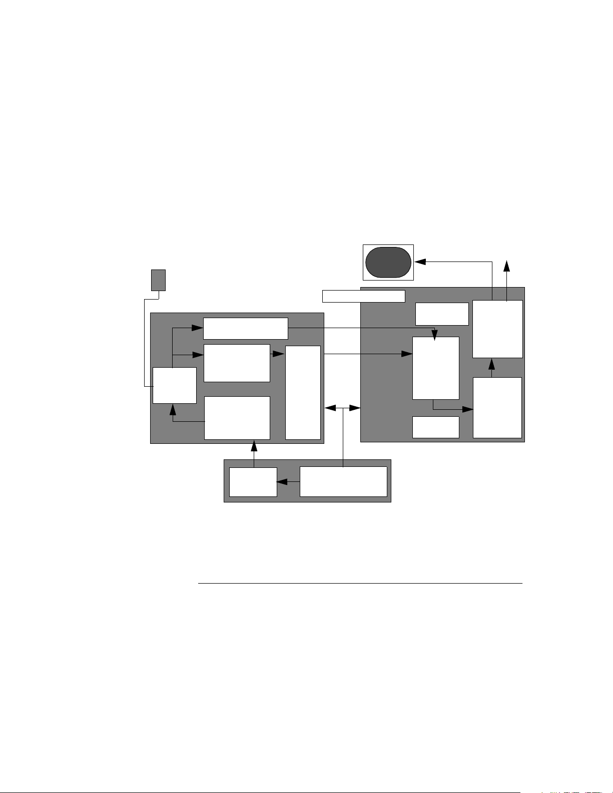
Figure 5-1 illustrates the basic Sequoia system architecture.
Xdcr
Audio FRQ
Spectral Beamformer
Digital Receive
Xmt/Rcv
Switching
Imageformer Subsystem
Beamformer
Transmit
Beamformer
Control
User
PW
CW
Color
2-D
M-mode
Monitor
Interface
System
Supervision
Memory
&
Scan
Conversion
AEGIS system &
Ethernet
DIMAQ Integrated Workstation
OEMs
Peripheral
Interface
Video
Conversion
PPS
Power Subsystem
Main Power Supply
Figure 5-1 Basic System Architecture of Sequoia System
Module 5-6 Sequoia Service Training Manual P/N 59155 Rev. 1
Page 7

Acuson Confidential Coherent Imageformer
COHERENT IMAGEFORMER
COHERENT
IMAGEFORMER
MULTIPLE
EAMFORMATION
B
The Coherent Imageformer subsystem performs three primary
functions. These are:
• Transmission of focused ultrasound energy
• Receive and process of back scattered ultrasound energy
• Control of transmit and receive parameters to sweep the
ultrasound beams through the field of view
The Coherent Imageformer performs these functions by setting the
phase and amplitude parameters for each transmit/r eceive element
in the transducer. Sophisticated computer control of these
parameters provides extensive flexibility in controlling the
transmitted ultrasound beam and processing the back-scattered
energy picked up by each transducer element.
The Multiple Beamformer is a new beamformer architecture that
utilizes up to 512 digital processing channels. This unique
architecture:
• Processes phase and amplitude
• Acquires multiple beams simultaneously to capture
information
• Acquires multiple beams in the same amount of time that a
single beamformer acquires a single beam
COHERENT IMAGEFORMER PCBS
The high-speed data acquisition generated by multiple
beamformers translates directly into significantly higher frame
rates, higher spatial resolution and increased sensitivity in 2-D and
Color Doppler imaging modes.
Phase information is utilized by the Coherent Imageformer to
acquire additional information that cannot be done without the use
of phase.
Five major board types make up the Coherent Imageformer. Each of
these boards performs specific functions in the formation of an
ultrasound image cell.
BOARD NAME ACRONYM
Transmitter Board TX
Multiplexer Board MX
Receiver Board RX
Beamformer Board BF
Controller Board CN
P/N 59155 Rev. 1 Sequoia Service Training Manual Module 5- 7
Page 8

Module 5 - System Architecture Acuson Confidential
THEORY OF OPERATION
TRANSMISSION All Coherent Imageformer functions are controlled by the
Controller board (CN). Data regarding the type of ultrasound
information to acquire, (e.g., 2-D mode, Color, Pulse Doppler, Depth
of Scan, Power to use, etc.) are passed to the CN board on the
system control bus.
The CN then passes parameter data to the transmitter boards on the
Imageformer bus. In addition, configuration data is also passed to
the Multiplexer (MX) and Receiver (RX) boards.
The Tr ansmitter (TX) boards use this data to determine the pulse
characteristics and time delay requir ed. The digital pulse waveform
is passed to a D/A converter, which creates the analog wave used to
drive a high voltage amplifier. This amplifier output drives the
transducer piezoelectric-crystal element. Two TX boards may be
used to process a total of 512 digital processing channels. The high
voltage pulses from the TX board are passed to the Multiplexer
board (MX).
The MX board switches the transmit pulses to the appropriate
transducer element, based upon the transducer(s) connected and
the scan format used.
Each transducer consists of a number of piezoelectric-crystal
elements. A piezoelectric-crystal element changes spatially when a
voltage is applied across it. On receiving a high-frequency electric
wave, the piezoelectric-crystal element vibrates and creates a highfrequency ultrasound wave.
The ultrasound wave propagates into the tissue of the patient being
scanned. Wherever there is a change in the acoustic impedance,
such as the interface between dissimilar tissues, a portion of the
ultrasound wave is reflected. The magnitude of the reflected wave
is a function of the difference in acoustic impedance between the
tissues.
Module 5-8 Sequoia Service Training Manual P/N 59155 Rev. 1
Page 9

Acuson Confidential Theory of Operation
RECEPTION Immediately after transmitting the ultrasound wave, the system
begins acquiring echo data. A piezoelectric-crystal element not only
changes geometry when a voltage is applied, it also creates an
electric charge when the geometry of the element is mechanically
changed. The ultrasound echo data returning from the patient
excites the piezoelectric-crystal elements. The crystals output a
small electric signal that is proportional to the amplitude of the
received ultrasoun d waves.
The MX board r outes these i n dividual s ignal s to th e Recei ver bo ard
(RX). The RX board provides initial amplification of the echo data.
The signals are processed for gain and then passed to the
Beamformer board (BF), where apodization occurs. The RX board
also creates the clock signals used to synchronize system
operations.
During spectral Doppler operation, the Doppler data is passed to
the Spectral Doppler Preprocessor located on the RX board. The PW
Doppler data is sampled only at the range gate. CW Doppler data is
acquired from the entire sample line. The Doppler data is then
processed and the quadrature data I&Q derived. The I&Q data are
then digitized and placed on the RX I/Q data path for processing
and display by the DIMAQ workstation.
The Beamformer board (BF) rece ives the back-scatter ed echoes from
each receive channel. By processing echoes from numerous
transducer arrays, the BF defines a series of coherently-focused
image cells.
Two BF boards may be used to process four different ultrasound
beams utilizing a total of 512 digital processing channels.
Figure 5-2 diagrams the Imageformer functions.
P/N 59155 Rev. 1 Sequoia Service Training Manual Module 5- 9
Page 10
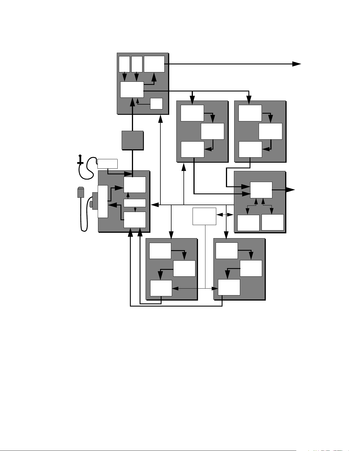
Module 5 - System Architecture Acuson Confidential
Freq
Gain
Block
LVA
Gen
SDP
DIMAQ
Workstation
To
AUX
Amplifier
Connectors
MP
MX
RX
RI
RMX
Control &
Calibration
TMX
MAC
PWG
DAC
ADC
CFB
ADC
BFP
CFB
BF-A BF-B
PPS
ACP
PWG
DAC
BBF
BFP
CN
To
DIMAQ
Workstation
FCP
HV
HV
Output
Amplifier
TX-A
Output
Amplifier
TX-B
Figure 5-2 Imageformer Block Diagram
Module 5-10 Sequoia Service Training Manual P/N 59155 Rev. 1
Page 11

Acuson Confidential Transmitter Board
TRANSMITTER BOARD
TX3
Part Number TX2 35282
Part Number TX3 39142
Quantity Cardiology: 1, Radiology: 2
Power Supplies +5 VDC, +5.5 VDC, -5.7 VDC,
Signals In TX Apodization, TX Delay
Signals Out TX Signal (1-64)
FUNCTION The Transmitter board (TX) provides the electrical signal used to
drive the piezoelectric elements in the transducer. The TX is
controlled by the Controller board (CN) via the IAB bus.
Apodization and delay parameters are passed to the TX by separate
signal lines.
The programmable wave generator (PWG) ASIC generates a digital
transmit waveform for up to four beams.
±12 VDC; Vxmt
TROUBLESHOOTING
H
INTS
The pulse parameters are specified for each transducer element
based on the ultrasound line being fired. The parameters are
converted to an analog signal, which is used to drive a high voltage
amplifier. The high voltage amplifier uses the output from the
Programmable Power Supply (PPS). The PPS is set by software to a
given voltage based on the ultraso und line being fired. The highvoltage transmit pulses for each transducer element are then passed
to the MX board.
Failures of the TX board are most likely to interrupt a single
transmitter channel only. This is unlikely to be visually perceptible.
If problems are suspected, replace the board to check for image
improvement.
P/N 59155 Rev. 1 Sequoia Service Training Manual Module 5- 11
Page 12

Module 5 - System Architecture Acuson Confidential
MULTIPLEXER BOARD
MX2/3
Part Number MX2 Cardiology: 39052, Radi ology: 36262
Part Number MX3 Cardiology: 50642; Radi ology: 39132
Quantity One
Power Supplies +5.5 VDC;
Signals In TX Signal (64 or 128 channels), TX Off, Control
data
Signals Out MX Signal (64 or 128 channels)
FUNCTION The Multiplexer board (MX) provides the electrical connection
between the Imageformer and the transducers supported by the
Sequoia system.
The MX board has three functions:
±12 VDC; ±100 V
TROUBLESHOOTING HINTS
• To switch the electrical transmit pulse from a selected
transmitter channel to the appropriate transducer element.
• To switch the appropriate transducer element to the proper
receive channel.
• Provide a signal path for calibration signals generated by a
selected transmitter channel to be monitored by a selected
receive channel.
The MX board is controlled by the Controller board (CN) via the
MX/RX Bus. The CN configures the MX based upon the
transducer(s) connected and selected.
Calibration signals may be passed from the Transmitter board (TX)
to the Receiver board (RX) via the MX board. If a transmit or receive
channel fails diagnostics and replacement of the board does not
correct the problem, it is possible that the MX is not providing the
necessary signal path.
Module 5-12 Sequoia Service Training Manual P/N 59155 Rev. 1
Page 13

Acuson Confidential Receiver Boa rd
RECEIVER BOARD
RX
Part Number RX2 Cardiology: 39052, Radiology: 32012
Part Number RX4 Cardiology: 51642; Radiology: 51562
Quantity One
Power Supplies +5.5 VDC; -5.7 VDC;
Signals In MX Signal (64, or 128)
Signals Out RX Signal, RX I/Q, Master System Clocks
FUNCTION The Receiver board (RX) operates in two ways, depending upon the
type of ultrasound data being processed. When a 2-D, F-mode or Mmode ultrasound line is being processed, the receive signal from
MX for each channel is acquired and passes through circuitry that
amplifies and preprocesses it. The signal is then passed to the
Beamformer board (BF) for construction of an image cell.
±12 VDC
TROUBLESHOOTING
INTS
H
When PW Doppler or CW Doppler data is being acquired, the data
path is quite different. The Doppler data is amplified and
preprocessed based on range gate position (PW), or acquired over
the entire sample line (CW). The Doppler signals are then shifted
temporally to create a coherent ultrasound image cell.
The temporally shifted Doppler data is summed and passed to the
Color Spectral Doppler board (CSD) for conversion from time
domain to the frequency domain.
The RX board also generates the master clock signals used by the
system to synchronize operations.
The RX board is the point in the system where 2-D, F-mode, and
M-mode signal processing diverge from PW Doppler and CW
Doppler signal processing. For this reason, it is valuable to check
each mode to see if symptoms that appear are present in each.
For instance, if a 2-D image has noise artifacts in one area of the
image, then placing the PW Doppler cursor in that area provides an
important troubleshooting clue. If the noise is present in both
modes, then it is being introduced at RX board, or earlier in the
processing path (e.g., RX, MX, TX, Power Supplies). If the noise is
only in PW Doppler then it is being introduced in the RX boa rd or
later in the PW signal path (e.g., RX, CSD).
Failures of the RX board are most likely to interrupt a single signal
path to/from the transducer. This is not visually perceptible. If
problems are suspected, replace the board to check for image
improvement.
P/N 59155 Rev. 1 Sequoia Service Training Manual Module 5- 13
Page 14

Module 5 - System Architecture Acuson Confidential
Failure of the clocks causes the system to stop executing the boot
sequence. The system display and boot appear “dead.”
RI BOARD The Receiver Interconnect board or RI is located on top of the MX
and RX boards in the cardcage. The main functions of this board
are:
• Connects the signal from MX board to the RX board
• Passes clock signal to the MX board
Two versions of the RI boards are available. P/N 31992 is used on
Sequoia 512 ultr asound syst ems, and P /N 35662 is used for Seq uoia
256 echocardiography systems.
Module 5-14 Sequoia Service Training Manual P/N 59155 Rev. 1
Page 15

Acuson Confidential Beamform er Board
BEAMFORMER BOARD
BF3
Part Number 39152
Quantity Cardiology: 1, Radiology: 2
Power Supplies +5 VDC, +5.5 VDC, -5.7 VDC
Signals In RX(0-63)
Signals Out BF I/Q
FUNCTION The Imageformer subsystem contains one Beamformer board (BF)
in 256-channel syste ms and two BF boards in 512-channel systems.
The BF performs digitizing of data from each receiver channel. This
data is then processed by Acuson-developed proprietary BFP ASIC
circuits. These ASICs perform the delay, apodization, phase adjust,
and summation of the individual channels. The summed data is
then mixed to convert it into a baseband signal (I&Q), which is then
passed to the Controller board (CN). Systems with two BF boards
have their outputs summed on the CN board.
Primary control and setup of the board for each ultrasound line is
done by the Controller board (CN), over the IAB Control bus.
TROUBLESHOOTING
INTS
H
Failures of the beam formation process are generally perceived as
one or more ultrasound lines being affected throughout the depth of
the scan. The failure may be loss of data, noisy data, or other
artifacts affecting a subset of the ultrasound lines throughout the
depth of the scan.
On 512-channel systems, the location of the two BF boards can be
switched, to see if the affected ultrasound lines move to a different
part of the image area. If the artifact moves, the BF board is the
defective assembly.
P/N 59155 Rev. 1 Sequoia Service Training Manual Module 5- 15
Page 16

Module 5 - System Architecture Acuson Confidential
CONTROLLER BOARD
CN2/3
Part Number CN2 35822
Part Number CN3 39522
Quantity One
Power Supplies +5 VDC
Signals In BF I/Q, PPS status
Signals Out 2-D, M Mode, F Mode data, PPS control
NOTE: CN3 is required for Sequoia Signature Option.
FUNCTION The Controller board (CN) provides the overall control and timing
for the Imageformer subsystem. It has a n A c quisition Control
Processor (ACP) that controls the Imageformer and interfaces with
the DIMAQ workstation subsys tem to ascertain the scan format
(e.g., depth, focal zone, mode, gain vectors, etc.).
TROUBLESHOOTING HINTS
Based on the scan format, the CN determines the parameters
required to configure each board in the Imageformer, as well as the
CSD and BDM boards, to achieve the correct scan format. These
parameters are passed to each board over the Acquisition Control
bus.
The Focus Control Processor (FCP) generates transmit and receive
apodization profiles. The CN also processes the ultras ound data
from the BF board(s). When two BF boards are present in a system,
the echo data is summed and gain-corrected by the CN.
F-mode data is then passed to the Color Spectral Doppler board
(CSD), where the Color Doppler velocity data is derived from the
ultrasound data. 2-D and M-mode data are passed to the 2-D
mode/M-mode Processin g and System Data Memory board (BDM)
for preprocessing, temporal processing and storage.
Because the CN board contro ls the other boar ds in the Imagefo rmer,
failure of the CN could create a wide variety of imaging problems.
In general, if an imaging problem cannot be resolved by replacing a
suspected Imageformer board or boards, then replacing the CN
would be recommended.
Module 5-16 Sequoia Service Training Manual P/N 59155 Rev. 1
Page 17

Acuson Confidential DIMAQ Integrated Ultrasound Workstation
DIMAQ INTEGRATED ULTRASOUND WORKSTATION
The integration of a special purpose ultrasound workstation into
the system architecture is at the heart of the Sequoia system’s digital
image management capabilities.
The DIMAQ workstation has numerous system capabilities which
allow it to:
• Expand the science of quantification
• Expand Network and AEGIS system capability
• Perform JPEG compression, direct DICOM connectivity and
display of multiple static and dynamic im ages
• Spec i al applicat io ns , su c h as stress echo.
The primary function of the DIMAQ workst ation is the display of
data received from the Coherent Imageformer. Ultrasound data can
be acquired in one of four formats, linear, sector, curved, or Vector
Wide-View Array. None of these formats are similar to the video
raster format, therefore a conversion process must take place in
order to display the ultrasound data on a video monitor.
THE DIMAQ WORKSTATION PCBS
In addition to this, the DIMAQ workstation incorpora tes a number
of other functions. These are to process ultrasound 2-D mode and
Doppler data, to perform calculations, and to interface the system to
various input and output devices including the user controls.
Overall control of the system is the job of the System Supervisory
Processor , which is located on the Reconstruction Display Processor
board (RDP).
The DIMAQ workstation is made up of six printed circuit boards.
Each of these boards performs specific functions in the formation
and display of an ultrasound image cell. They are:
BOARD NAMES ACRONYMS
Color Spectral Doppler Board CSD
2-D mode/M-mode Acquisition & Preprocessing and
System Data Memory Board
Reconstruction Display processor Boa rd RDP
Input/Output Video Board IOV
Input/Output Expansion Board IOE
BDM
Peripheral Interface Controller Board PIC
P/N 59155 Rev. 1 Sequoia Service Training Manual Module 5- 17
Page 18

Module 5 - System Architecture Acuson Confidential
THEORY OF
O
PERATION
ACQUISITION AND
REPROCESSING
P
The DIMAQ workstation, as shown in the functional block diagram
in Figure 5-3, performs the following major functions for normal 2D mode imaging:
• Overall control of the Sequoia system
• Storage of ultrasound data for CINE functions
• Conversion of ultrasound scan format to video scan format
• Image enhancement and postprocessing
• Conversion to various video formats
• Alphanumeric and graphic display
• Interface to operator (front panel controls)
• Interface to peripheral recording devices (AEGIS system, VCR,
Printers, etc.)
Digital ultrasound video information is sent to the DIMAQ
workstation from the Coherent Imageformer. In the DIMAQ
workstation, the information is stored in the proper locations in the
system data memory.
RECONSTRUCTION From the system data memory, data is passed to the Reconstruction
Display Processor (RDP). Here, 2-D and Color Doppler data are
combined, M-mode or pulse Doppler data are stored to strip
displays, and graphics and data block information are overlaid.
VIDEO CONVERSIONS The data is then passed to the Input/Output Video board (IOV).
Here the data is converted to a variety of video standards.
Progressive RGB video is provided to the internal monitor. Also,
interlaced composite and component video are derived from the
progressive RGB. NTSC and PAL video standards are supported.
DIMAQ WORKSTATION SUBSYSTEM CONTROL
SYSTEM SUPERVISORY PROCESSOR
The DIMAQ workstation provides overall control of the system,
including user interface and high level control of other processors
which, in turn, control subsystems. The main processor is the
System Supervisory Processor (SSP) and is located on the
Reconstruction Display Processor board (RDP).
This processor communicates with the BDM and CN via the system
control bus. The SSP can also communicate with the PIC board via
the Aux bus. This is used to configure the inputs and outputs from
the PIC board, as well as to communicate with the SCSI devices on
the system.
Module 5-18 Sequoia Service Training Manual P/N 59155 Rev. 1
Page 19

Acuson Confidential DIMAQ Integrated Ultrasound Workstation
Whenever a key is pressed or a knob is adjusted, the SSP interprets
this data and configures the system accordingly.
SCAN FORMATS High-level information about the scanning mode is passed to the
CN board. The CN, in turn, configures the Coherent Imageformer to
scan in a mode that reflects the user’s parameters.
The SSP also sends high-level configuration information to the
BDM. The BDM is configured to capture data from the Coherent
Imageformer, as appropriate for the scanning mode.
When a change is made to the scanning parameters, the
corresponding graphic element on the monitor is changed to blue
while the transition to the new format is performed. When the
system is displaying data as selected by the new parameters, the
graphic element reverts to white. This allows the user to know
precisely when the system has completed reconfiguration of the
scan format.
USER INTERFACE The User Interface provides the interface between the user and the
Sequoia system. One of the components of the User Interface is the
Front Panel Processor (FPP) board. The FPP monitors the status of
the user controls and, when changes occur, sends an interrupt to the
System Supervisory Processor (SSP) located on the RDP board. The
SSP then initiates the sequence of events needed to configure the
Sequoia system as required.
The User Interface is designed in a modular fashion. The FPP board
mates to the switch assembly via stand offs and hard connectors.
The trackball, QWERTY (Alphanumeric keyboard), and DGC
potentiometers assembly are connected with ribbon cables.
P/N 59155 Rev. 1 Sequoia Service Training Manual Module 5- 19
Page 20
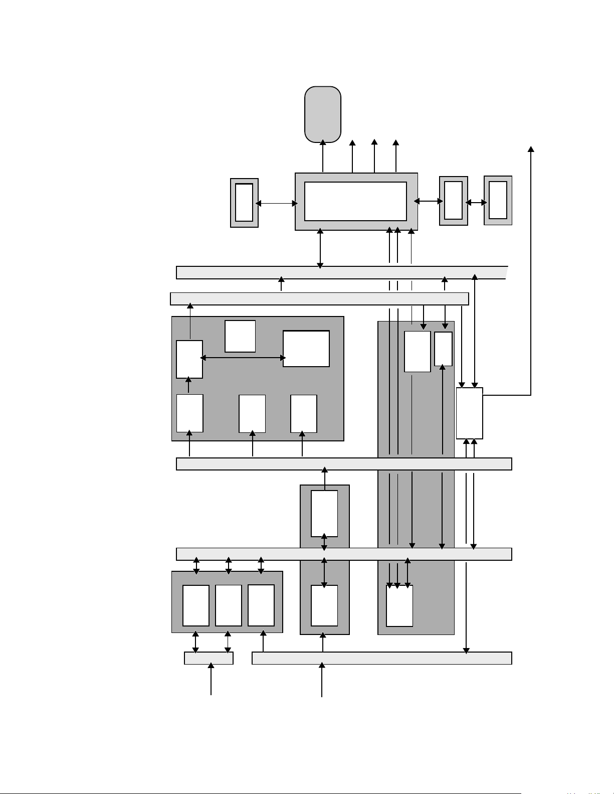
Module 5 - System Architecture Acuson Confidential
Monitor
Serial Ports
SCSI
Video/Audio
User
Controls
Digital
Video Bus
Aux Bus
FIZ
Physio
Module
PIC
Peripheral
Interface
Conntroller
Audio I/O
Physio I/O
FPP
Front Panel
Processor
Ethernet
RDP
CSD
Video
Display
Image
Reconst.
Doppler
Buffer
Block
Audio
Processor
Text &
Spectral
Doppler
Processor
Static
Graphics
CDI
Post-Proc.
Color
Doppler
Processor
System
Supervisory
Processor
Waveform
Graphics
BDM
Processor
System
Data
B/M Mode
Acq. and
Memory
Preproc.
IOV
I/O
Processor
Video
Standards
SDM Data
Port
Conversion
I/O Expansion
(JPEG Compr.)
IOE
SDM
Reconstruction Bus
SDM
Acq. Bus
Acq
RX
I/Q
Doppler
Serial
Data
Acq
I/Q
Figure 5-3 DIMAQ Workstation Block Diagram (IOE3)
Module 5-20 Sequoia Service Training Manual P/N 59155 Rev. 1
Control Bus
Page 21

Acuson Confidential DIMAQ Integrated Ultrasound Workstation
Monitor
Serial Ports
SCSI
Video/Audio
Ethernet
User
Controls
Digital
Video Bus
Aux Bus
FIZ
Physio
Module
PIC2
Peripheral
Interface
Conntroller
Audio I/O
Physio I/O
FPP
Front Panel
Processor
RDP
CSD
Video
Display
Image
Reconst.
Doppler
Buffer
Block
Audio
Processor
Text &
Spectral
Doppler
Processor
Static
Graphics
CDI
Post-Proc.
Color
Doppler
Processor
System
Supervisory
Processor
Waveform
Graphics
Processor
BDM
System
Data
Memory
B/M Mode
Acq. and
Preproc.
IOV2
I/O
Processor
Video
Standards
SDM Data
Port
Conversion
I/O Expansion
(JPEG Compr.)
SDM
Reconstruction Bus
SDM
Acq. Bus
Acq
RX
I/Q
Doppler
Serial
Data
Acq
I/Q
Figure 5-4 DIMAQ Workstation Block Diagram (IOV2/PIC2)
P/N 59155 Rev. 1 Sequoia Service Training Manual Module 5- 21
Control Bus
Page 22

Module 5 - System Architecture Acuson Confidential
COLOR AND SPECTRAL DOPPLER BOARD
CSD1/2
Part Number CSD1 32082
Part Number CSD2 41462
Quantity 1
Power Supplies +5VDC, -5.7VDC
Signals In RX I/Q, Mode I/Q
Signals Out Spectral frequency da ta , spectral audio data,
Color Doppler data
FUNCTION The CSD board processes the ultrasound echo data to extract
spectral and color flow data. The CSD may be thought of as
comprising three distinct functional subsections. These are spectral
Doppler processing, audio Doppler processing, and Color Doppler
processing.
SPECTRAL AND
UDIO PROCESSING
A
COLOR DOPPLER PROCESSING
TROUBLESHOOTING HINTS
The spectral and audio sections of the CSD board receive RX I&Q
data from the RX board directly. Echo clutter is removed from the
signal. Then the data is converted from time domain to frequency
domain. Both are then passed to the system data memory on the
BDM for further processing and display.
The Color Doppler data is received from the CN board as F-mode
I&Q. The color flow parameters are extracted from the raw echo
data and processed to derive a velocity estimate. The data is then
passed to the system data memory on the BDM for further
processing and display.
The CSD board is divided into three functional subsections, all
processing data independently of each other. This provides
important clues about possible failures.
When attempting to isolate a problem, first note the modality in
which the problem occurs. If a manifestation of the problem occurs
in all modalities then it is highly unlikely that CSD is responsible.
Problems likely to be related to the CSD board are those which
appear in only one of the three modalities discussed earlier.
Module 5-22 Sequoia Service Training Manual P/N 59155 Rev. 1
Page 23

Acuson Confidential BDM Board
BDM BOARD
BDM1/2
Part Number BDM1 32062
Part Number BDM2 41472
Quantity 1
Power Supplies 5VDC
Signals In Acq. I/Q
Signals Out SDM bus
FUNCTION The 2-D mode, M-mode, Spectral and System Data Memory board
consists of two distinct functional components: the 2-D mode /Mmode Acquisition and Preprocessing (BAP) and System Data
Memory (SDM). The BAP performs all detection an d pr e p r o cessing
operations for B/M mode. The SDM is a high-bandwidth, highcapacity memory subsection for use in temporal processing, cine
data storage, and buffering between acquisition and recons truction
functions.
SMM PROCESSOR The System Memory Manager Processor (SMM) is responsible for
management an d a lloc ation o f th e SDM mem ory, managem ent, an d
synchronization of data to be displayed. Any access to SDM
memory must have prior setup performed by the SMM.
P/N 59155 Rev. 1 Sequoia Service Training Manual Module 5- 23
Page 24

Module 5 - System Architecture Acuson Confidential
RECONSTRUCTION AND DISPLAY PROCESSOR BOARD
RDP2/5
Part Number RDP2 38282
A
Part Number RDP5
Quantity 1
Power Supplies +5VDC
Signals In 2-D, M Mode Spectral, VCR playback, and AEGIS
Signals Out Setup parameters for the system, digital
A. RDP5 is compatible with Sequoia 4.0 and higher.
FUNCTION The RDP performs two primary functions. First, it has the System
Supervisory processor located on it. Second, it takes the data for
each mode from the BDM board and reconstructs an image.
53552
system review data
progressive RGB video
The RDP board constantly receives data from the BDM board,
overlays or mixes color data on the 2-D image, incorporates
graphics, and displays M-mode and spectral strip data, etc. as
required. When a frame of data has bee n completed, the data is read
out to the IOV board.
SSP The System S upervisory processor is, as the name suggests,
responsible for managing the system at large. This includes
processing user requests initiated at the user interface, setup of the
Imageformer subsystem for the scanning mode selected,
configuration of each of the PCBs to process the data required, etc.
The SSP also handles communica tion with most of the Sequoia
system and maintains system control bus accuracy.
TROUBLESHOOTING HINTS
The SSP performs many validations of its own functionality and its
ability to communicate with o ther boards during the power on
cycle. If the SSP fails to complete these self-tests, then the system
will fail to boot.
The other function of RDP board is to read out the image, spectral,
flow, VCR, or AEGIS system data from the BDM board, construct
one image frame and pass the image format data to the IOV. Failure
of this process may result in an image reconstruction problem or no
update on the frame displayed.
Module 5-24 Sequoia Service Training Manual P/N 59155 Rev. 1
Page 25

Acuson Confidential Input/Output Video Board
INPUT/OUTPUT VIDEO BOARD
IOV1/2
Part Number IOV 33342
A
Part Number IOV2
Quantity 1
Power Supplies +5VDC, +12VDC, -5.7VDC, ±12VDC
Signals In Video data from RDP, Audio data from BDM,
Signals Out Progressive RGB, S-VHS, VHS, voidable or NTSC
A. IOV2 requires a PIC2 and eliminates the IOE3.
FUNCTION The primary function of the IOV board is to provide conversion to
and from various video format standards; e.g., NTSC, PAL; S-VHS
and VHS. The video format used by the system monitor is a
progressive, i.e., noninterlaced RGB video.This format is not
compatible with most of the peripherals.
41482
VCR playback data, AEGIS system review data
video formats, system audio.
TROUBLESHOOTING HINTS
The IOV board supports other processes as well. These include
processing audio data from BDM, and interfacing with the Physio/
ECG board (FIZ).
The IOV2 also provides JPEG compression circuitry that was
previously on the IOE3.
The IOV board is responsible for the video format conversion. If
video is corrupted on one peripheral device but not on the other
(e.g., video is OK on the display monitor but VCR recording is not
correct and interface cable has been replaced), then it is likely that
IOV is malfunctioning.
If the video is corrupted at all outputs than the RDP may be giving
corrupted data to the IOV board, or the IOV itself is corrupting the
video data.
Communication problems with FIZ board may be caused by the
IOV board. If replacing the FIZ board doesn’t correct the problem,
try replacing the IOV board.
P/N 59155 Rev. 1 Sequoia Service Training Manual Module 5- 25
Page 26

Module 5 - System Architecture Acuson Confidential
INPUT/ OUTPUT EXPANSION BOARD
IOE3
Part Number 42532
Quantity 1
Power Supplies +5 VDC
Signals In AEGIS system data, Ethernet communication
Signals Out AEGIS system data, Ethernet communication
FUNCTION The IOE board provides the hardware needed to interface to
Ethernet networks. The Sequoia system uses 10BaseT Ethernet
connection.
In addition, the IOE board has provisions for installing other circuit
boards as daughter boards, to allow for future additions to the
system’s functionality.
Newer systems have the IOV2 and PIC2 boards, which eliminate
the need for the IOE3.
TROUBLESHOOTING
INTS
H
The IOE board has sole responsibility for Ethernet communication
of the Sequoia system to an Ethernet network. If the network setups
and the interface to the network are OK then the IOE board may be
replaced to correct the problem.
Module 5-26 Sequoia Service Training Manual P/N 59155 Rev. 1
Page 27

Acuson Confidential Peripheral Interface Controller Board
PERIPHERAL INTERFACE CONTROLLER BOARD
PIC1/2
Part Number PIC 30132
A
Part Number PIC2
Quantity 1
Power Supplies +5 VDC, +12 VDC, -5.7 VDC, and ±12 VDC
Signals In All Video formats from IOV board, All playback
Signals Out All Video formats to Peripheral devices, All
A. PIC2 requires the IOV2.
43242
video from the Peripheral devices, Audio from
BDM, Audio from Peripherals.
playback video to the IOV board, Audio to
Peripherals, speakers, headphones.
FUNCTION The PIC board provides interconnections between the Sequoia
system card cage and other assemblies or peripheral devices. These
connections are made through the rear panel located at the rear of
the Sequoia system.
Assemblies that are connected to the PIC board include the FPP
board, FIZ board, Audio speakers, Monitor assembly, and the SCSI
devices. Peripheral devices connected to the PIC bo ar d may in clude
a VCR, Printers, Multi-Image camera, or the QV150.
The PIC board stores the system serial number in the BBRAM, and
contains circuitry for reset, start-up and shutdown, etc.
The PIC board also has the capability to monitor many aspects of
the system. These include power supply voltages, fuses, AC line
voltage, and system temperature.
The PIC2 board provides the hardware needed to interface to
Ethernet networks. The Sequoia system uses 10BaseT Ethernet
connection.
TROUBLESHOOTING HINTS
The PIC board provides interconnections between various
assemblies and peripherals. It is also an integral part of the power
up/down sequences.
Generally, if a problem persists a fter replacing the assembly or the
interface cabling, then try replacing the PIC board.
P/N 59155 Rev. 1 Sequoia Service Training Manual Module 5- 27
Page 28

Module 5 - System Architecture Acuson Confidential
PHYSIO INTERFACE MODULE
FIZ
Part Number 35992
Quantity 1
Power Supplies +5 VDC and ±12 VDC
Signals In Three lead ECG, Pulse, Phono, and Respiratory
transducers, AUX Inputs.
Signals Out ECG, Pulse, Phono, and Respirato r y trace data,
AUX outputs.
FUNCTION The Physio Interface module is located above the card cage with the
input/output jacks available at the left side of the system. The FIZ
module provides a three-lead ECG input, pulse, phono, and
respiratory input. Additionally, there are input ports available for
auxiliary functions. Refer to the user manu al for the supported
auxiliary devices.
TROUBLESHOOTING
H
INTS
After configuration by the system supervisory processor on the
RDP, based on the user controls, the FIZ module acquires data and
passes it to the IOV over the same bus used for configuration.
The FIZ module contains multiple dat a ch annels, all of which are
passed to the Sequoia system on a single bus. It is useful to know if
the problem exists in one channel or all.
The user controls for the FIZ module are located on the User
Interface. Check for a stuck or broken switch on the User Interface.
Also verify operation of the gain control encoder for gain- or
position-related problems.
Module 5-28 Sequoia Service Training Manual P/N 59155 Rev. 1
Page 29

Acuson Confidential Front Panel Processor Board
FRONT PANEL PROCESSOR BOARD
FPP
Part Number 31642
Quantity 1
Power Supplies +5 VDC, +12 VDC
Signals In User Interface switch selections
Signals Out User Interface changes to SSP on RD P board, LED
annunciators, Two line LCD display.
FUNCTION The PIC board provides the interface between the Sequoia system
card cage and the user. The FPP has a processor on board that
continually monitors the status of the user controls. When changes
occur, the FPP sends an interrupt to the System Supervisory
processor located on the RDP board. The SSP interrog at es the user
controls to find out which ones have been changed and initiates the
sequence of events needed to configure the Sequoia system as
required.
TROUBLESHOOTING HINTS
The User Interface is designed in a modular fashion. The FPP board
mates to the switch assembly via standoffs and hard connectors.
The trackball, alphanumeric keyboard, and the DGC
potentiometers assembly are connected with ribbon cables. Two
additional modules, which contain more controls, are connected to
the FPP by ribbon cables.
All controls except the DGC pots are switches or digital encoders.
The switches are decoded through the use of a switch grid, that is,
each switch occupies the intersection of a pair of wires. The
switches share each wire with other switches, but only one switch
occupies each intersection.
The PIC board provides interconnections between various
assemblies and peripherals. It is also an integral part of the Power
on/off sequences.
Generally , if the pr oblem persists after replacing the assembly or the
interface cabling, try replacing the PIC board.
P/N 59155 Rev. 1 Sequoia Service Training Manual Module 5- 29
Page 30

Module 5 - System Architecture Acuson Confidential
2-D/ M-MODE SIGNAL FLOW
TRANSMISSION All Coherent Imageformer functions are controlled by the
Controller board (CN). The CN passes parameter data to the TX
boards on the Imageformer bus. In addition, configuration data is
also passed to the MX and RX boards.
The high-voltage pulses from the TX board are passed to the
Multiplexer board (MX). The MX board directs the transmit pulses
to the appropriate transducer element, based upon the
transducer(s) connected and the scan format used.
Each transducer consists of a piezoelectric-crystal element. A
piezoelectric-crystal element changes spatially when a voltage is
applied across it. On receiving a high-frequency electric wave, the
piezoelectric-crystal element vibrates and creates a high-frequency
ultrasound wave.
The ultrasound wave propagates into the tissue of the patient being
scanned. Wherever there is a change in the acoustic impedance,
such as at the interface between dissimilar tissues, a portion of the
ultrasound wave is reflected. The magnitude of the reflected wave
is a function of the difference in acoustic impedance between tissues
at their interfaces.
RECEPTION Ultrasound signal reception begins when the Coherent
Imageformer fires an ultrasound wave. The digital ultrasound data,
representing the instantaneous phase and amplitude values of the
analog ultrasound signal, are loaded into the BDM board. Her e, the
data is preprocesse d and loaded i nto the sys tem data memory. Each
frame of data is stored for CINE review and persistence functions.
The number of frames that may be stored varies, depending upon
the scan format used.
Persistence is implemented by the BDM board. It is achieved by
modifying the current and previous data with a complex algorithm
to remove temporally transient artifacts.
RECONSTRUCTION
AND DISPLAY
The 2-D mode data stored in the BDM board is transferred to the
RDP board, and mapped into the proper raster display format. The
2-D mode data is also combined with the graticules, static graphics,
alphanumer ic and waveform graphics that will ultimately appear
on the monitor.
The digital RGB progressive video is passed to the Input/Output
Video board (IOV). The IOV converts the digital RGB progressive
video into an analog video.
Module 5-30 Sequoia Service Training Manual P/N 59155 Rev. 1
Page 31

Acuson Confidential 2-D/ M-Mode Signal Flow
The analog video is then converted into various video standards,
e.g. NTSC and PAL video standards, interlaced composite or
component (Y/C) video as well as interlaced RGB. These formats
allow interfacing of peripheral recording devices on non-AEGIS
systems.
Analog progressive RGB video is then passed to the Peripheral
Interface Controller board (PIC). The PIC board provides buffering
and connections for each of the supported peripheral devices as
well as the system monitor. The progressive RGB is then passed to
the system video monitor for d isplay.
Figure 5-5 illustrates the 2-D mode/M-Mode signal flow.
P/N 59155 Rev. 1 Sequoia Service Training Manual Module 5- 31
Page 32

Module 5 - System Architecture Acuson Confidential
MO Dri ve
C31
Physio
System Audio
Monit or
Patient :
FPP
C31
Switch Panel
Hard Drive
Ethernet
UART
FIZ
Intf
IOV PIC
Audio
BDM
CSD
System
Audio
IOP
C31
RDP
Audio/VCR Playback/Physio
C31
C31
(DSP)
Audio
Doppler
(DAP)
Video
Buffers
System
Data
Memory
C31
Color
(CSP)
(VSC)
Video
Conversion
(VDB)
C31
B,D,F,M-Date
(SDM)
Prog
Video
Pal/NTSC
via SW
(IRB)
C31
Image
Reconstr.
(BAP)
Gain
Acq.
Processing
B, M- Data
C31
Cntlr
SCSI
IOE3
(SSP)
Supervisory
Processor
486
(SMM)
Memory
Manager
C31
(ALC)
Aegis
Control
486
CDI Data
CN
BF3_B
Doppler Data
+
BF3_A
Doppler
RX
(BBF)
Baseband
Filter
(BFP)
Dig.
Bfmr
A/D
64
64
MAC
cntl
Beamformer
(SDP)
Low Noise
128
Clks
Amplifier
(LVA)
MX2
RMX
(FCP)
Focus
Control
Apod/Delay
Gain/Interploation
MX/RX Bus
IAB Bus
Apodization/Delay
cntl
MXC
MP
TMX
DMA
C31
TX_B
TX_A
(PWG)
Pgm Waveform
Generator
486
(ACP)
Acquistion
Co ntro l
D/A
64
(HVA)
High Volt age
Amp
64
Figure 5-5 2-D Mode/M-Mode Sign al Path
Module 5-32 Sequoia Service Training Manual P/N 59155 Rev. 1
Page 33

Acuson Confidential Solo™ Spectral Doppler Signal Flow
SOLO™ SPECTRAL DOPPLER SIGNAL FLOW
DOPPLER THEORY Spectral Doppler is a way of processing echo data whereby the
frequency shift of the echo data is mapped to a strip display,
showing velocity distribution on one axis and time on the other.
The amount of shift is dependent upon the velocity of the reflector,
while the direction of shift (e.g., higher or lower pitch) is dependent
upon whether the reflector is moving towards or away from the
transducer . The frequency received by the transducer will be shifted
upwards if the target is moving towards the transducer and
downwards if the target is moving away. Echo data shifted in
frequency is called the Doppler signal. There is a major echo
component that is not shifted in frequency, which comes from
stationary tissue. This is known as clutter.
PULSE WAVE DOPPLER
Pulse W ave Spectral Doppler (PW Doppler) mode emits a pulse into
the body and then monitors the echo data over a time interval that
is set by the positioning of a range gate on the system monitor. By
sampling the data at a specific area, clutter can be reduced
dramatically.
NYQUIST LIMIT If the sampling rate is not adequate for high-frequency Doppler
shifts, artifactual lower frequency shifts are displayed. The
requirement that the sampling rate must be at least twice the
maximum frequency present in the Doppler signal is referred to as
Nyquist criterion. One half of the pulse repetition frequency (PRF)
is the Nyquist limit.
HIGH PRF There is a high PRF mode that may be invoked, wh ich results in a
phantom range gate at a depth other than the area of interest. If
there is no blood flow in the phantom area, this is an acceptable way
of increasing the PRF.
CONTINUOUS WAVE DOPPLER
Continuous Wave Doppler (CW Doppler) mode emits a continuous
ultrasound wave from a subset of the transducer elements. Other
elements of the transducer continuously monitor the echo data. This
allows many more samples than PW Doppler mode, but does not
allow for ranging of the data. For this reason, the signal received has
large amounts of clutter from the entire sample line. The Doppler
signal is very small relative to this clutter. The D oppler signal m ust
be separated from the clutter to be useful.
P/N 59155 Rev. 1 Sequoia Service Training Manual Module 5- 33
Page 34

Module 5 - System Architecture Acuson Confidential
SOLO™ SPECTRAL
D
OPPLER
The Sequoia 512 system has a unique spectral Doppler architecture.
It consists of a dedicated audio beamformer for spectral Doppler
only. The Doppler beam formation is performed at audio
frequencies because Doppler signal is an audio signal.
During spectral Doppler operation, the Doppler data is passed to
the Spectral Doppler Preprocessor (SDP) subsystem, located on the
RX board. The PW Doppler data is sampled only at the range gate.
CW Doppler data is acquired from the entire sample line.
The Doppler data is then processed and the quadrature data (I&Q)
derived. The I&Q data is then digitized and placed on the RX I/Q
data path for processing and display by the DIMAQ workstation.
T o achieve maximum performance, the spectral Doppler signal path
in the Sequoia system is significan tly different from the 2-D and
Color Doppler signal paths. Refer to Figure 5-6 for a diagram of the
signal path.
Spectral Doppler I&Q data is received at the Color Spectral Doppler
board (CSD), directly fro m the Receiver boar d (RX ) in the
Imageformer. The BF board and CN board do not process the
spectral echo data. The CSD provides the time domain to frequency
domain conversion. Furthermore, the CSD generates the audio
corresponding to the Doppler data received.
The spectral Doppler and audio data are then passed to the BDM
board where they are stored to allow CINE and other temporal
processing functions to be performed.
DISPLAY The spectral Doppler data is passed to the RDP where it is merged
with the spectral strip graphics as well as any other data to be
displayed on the monitor . This data i s then passed to the IOV board
and then to the PIC board in a fashion similar to the 2-D mode data.
AUDIO Audio data is passed directly from the BDM to the IOV board. It is
not processed by the RDP. The audio data is then passed to the PIC
board, which drives the speakers in the system, or is output to
headphones or a video recorder.
Module 5-34 Sequoia Service Training Manual P/N 59155 Rev. 1
Page 35

Acuson Confidential Color Doppler Signal Flow
COLOR DOPPLER SIGNAL FLOW
COLOR DOPPLER Color Doppler imaging is a modality whereby the frequency shift of
echo data is sampled at a large number of points within a defined
area of the image. This area is defined using a CD Res box. The
frequency shift samples are converted to a velocity est imation and
mapped onto the monitor as a color, e.g., blue if the signal is
frequency-shifted downward and red if the signal is frequencyshifted upward. This results in a graphic representation of blood
flow or other motion.
SST™ COLOR DOPPLER
The Sequoia 512 system incorpora tes SST Color Doppler. This is
enhanced by multiple Color Doppler beamformers and proprietary
Color Doppler processing, to improve S
emporal resolution. The Color Spectral Doppler (CSD) board
and T
receives color I&Q signals from the Controller (CN) board. The CSD
performs the majority of Color Doppler processing and uses
memory located on the BDM to store intermediate results of this
processing.
The color I&Q values represent the instantaneous data from a single
temporal and spatial point. Processing velocity information for
many points uses algorithm s that require multiple samples of the
same data point. For this reason, the results of color processing are a
“time averaged” velocity.
The results of CSD processing are passed to the BDM board for
storage. This is where the data is held for CINE review, as well as
temporal persistence processing. The data is then passed to the RDP
to be overlaid/mixed with the 2-D information. The color data is
then passed to the IOV board and then to the PIC board in a fashion
similar to the 2-D data.
Figure 5-6 illustrates the SST Color Doppler signal path.
ensitivity, Spatial resolution
P/N 59155 Rev. 1 Sequoia Service Training Manual Module 5- 35
Page 36

Module 5 - System Architecture Acuson Confidential
MO Dri ve
C31
Physio
System Audio
Monit or
Patient :
FPP
C31
Switch Panel
Hard Drive
Ethernet
UART
FIZ
Intf
IOV PIC
Audio
BDM
CSD
System
Audio
IOP
C31
RDP
Audio/VCR Playback/Physio
C31
C31
(DSP)
Audio
Doppler
(DAP)
Video
Buffers
System
Data
Memory
C31
Color
(CSP)
(VSC)
Video
Conversion
(VDB)
C31
B,D,F,M-Date
(SDM)
Prog
Video
Pal/NTSC
via SW
(IRB)
C31
Image
Reconstr.
(BAP)
Gain
Acq.
Processing
B, M- Data
C31
Cntlr
SCSI
IOE3
(SSP)
Supervisory
Processor
486
(SMM)
Memory
Manager
C31
(ALC)
Aegis
Control
486
CDI Data
CN
BF3_B
Doppler Data
+
BF3_A
Doppler
RX
(BBF)
Baseband
Filter
(BFP)
Dig.
Bfmr
A/D
64
64
MAC
cntl
Beamformer
(SDP)
Low Noise
128
Clks
Amplifier
(LVA)
MX2
RMX
(FCP)
Focus
Control
MP
cntl
IAB Bus
Apodization/Delay
TMX
Apod/Delay
Gain/Interploation
MX/RX Bus
MXC
DMA
C31
TX_B
TX_A
(PWG)
Pgm Waveform
Generator
486
(ACP)
Acquistion
Co ntro l
D/A
64
(HVA)
High Volt age
Amp
64
Figure 5-6 Color Doppler Signal Flow
Module 5-36 Sequoia Service Training Manual P/N 59155 Rev. 1
Page 37

Acuson Confidential ECG/Physio Signal Flow
ECG/PHYSIO SIGNAL FLOW
The Physio Interface allows an ECG, physio logic transducers and
auxiliary signals to be displayed on the Sequoia system monitor.
These signals may be used to trigger the 2-D mode image update
when using Pulsed Doppler or M mode, or they may be used as a
timebase when reviewing the CINE memory.
WARNING!
ECG
Pulse
Phono
Respiratory
Monitor
Peripherals
The Physio Interface is not designed for use in conjunction with
electrosurgery or diathermy equipment.
The Physio Interface board (FIZ) provides a three lead ECG input, a
heart sounds input, a pulse input, and a respiration input. There are
four additional inputs available for auxiliary functions. It is also
possible to configure two of the auxiliary inputs with output signals
under software control. Refer to the <Sequoia 512 User Manual for
supported modes.
The Physio Interface board is located above the card cage with the
input/output jacks available at the left side of the sy stem.
Under software control, the RDP sends configuration data to the
IOV board on the system control bus. The data is transferred from
the IOV board to the FIZ board on a dedicated bus.
After configuration, the FIZ board acquires data and passes this
data to the IOV over the same bus used for configuration. The IOV
routes this data to the BDM where it is stored for CINE review. The
physio data is then passed to the RDP, where the graphic display is
overlaid on the video image.
FIZ
Module
PIC
Physio
Bus
Interlaced RGB
Progressive RGB
Component Video
Composite Video
Physio
Data
IOV
BDM
RDP
Figure 5-7 ECG/ Physio Signal Path
P/N 59155 Rev. 1 Sequoia Service Training Manual Module 5- 37
Page 38

Module 5 - System Architecture Acuson Confidential
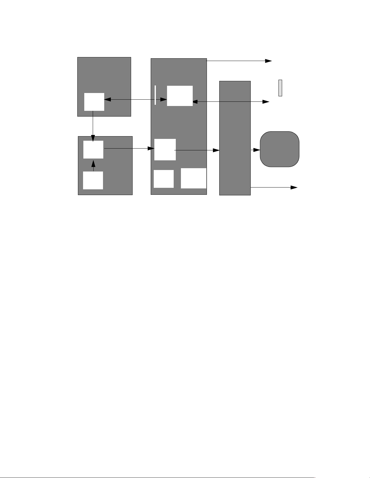
DIMAQ SYSTEM STORE AND REVIEW
ACQUISITION The Sequoia systems supports the acquisition of both static and
dynamic clips. For acquisition, the DIMAQ wo rkstation receives
video data from the IOV board in interlaced RGB format, performs
color space conversion to Y, R-Y, and B-Y (YUV), prior to JPEG
compression. The compressed images are stored in the SDM on the
BDM board, from which they can be decompressed for review, or
transferred out for storage on an MO drive or hard drive.
REVIEW For review, the IOE board in the DIMA Q workstation provides the
ability to decompress the video acquired in JPEG format, a nd store
the Run Length Encoded (RLE) YUV raster format data in SDM on
BDM board. This allows reconstruction by RDP board, and
subsequent conversion to video by IOV board, for display on the
monitor via the PIC board.
BDM
IOE
PIC
JPEG
SDM
Video
Display
Buffer
Reconstructio
n Block
Figure 5-8 DIMAQ System Signal Flow (Systems with IOE3 board)
RDP
Compress
Video
Standard
Conver-
SDM
Data
Port
-ion
I/O
Processor
IOV
<
MOD
;
Monitor
HD
Module 5-38 Sequoia Service Training Manual P/N 59155 Rev. 1
Page 39
Acuson Confidential DIMAQ System Store and Review
SDM
Video
Display
Buffer
Reconstructio
n Block
BDM
IOV2
<
JPEG
compress-
ion
RDP
Figure 5-9 DIMA Q S ystem Signal FLow (systems with IOV2/PIC2)
Video
Standard
Conver-
SDM
Data
Port
I/O
Processor
PIC2
;
Monitor
Ethernet
MOD
HD
P/N 59155 Rev. 1 Sequoia Service Training Manual Module 5- 39
Page 40

Module 5 - System Architecture Acuson Confidential
VCR PLAYBACK
ACQUISITION The Video Standard Converter (VSC) on IOV board receives the
external video input from VCR via the PIC board and converts it to
digital format for storage into SDM on BDM board.
VCR autocalibration data is digitized as part of video input process
and captured by this block.
PLAYBACK The video data stored in the BDM board is transferred to the RDP
board, and mapped into the proper raster display format.The
digital RGB progressive video is passed to the Input/Output Video
board (IOV). The IOV converts the digital RGB progressive video
into an analog video.
The analog video is then converted into various video standards.
Analog progressive RGB video is then passed to the Peripheral
Interface Controller board (PIC). The PIC board provides buffering
and the progressive RGB is then passed to the system video monitor
for display.
RDP
Video
Display
Buffer
Image
Reconstr
SDM
BDM
Video
Standar
d
SDM
Data
IOV
I/O
Process
Figure 5-10 Video Playback Signal Path
PIC
VCR
Monitor
Module 5-40 Sequoia Service Training Manual P/N 59155 Rev. 1
Page 41

Acuson Confidential Worksheet: System Architecture
WORKSHEET: SYSTEM ARCHITECTURE
1 Describe three hardware differences between the Sequoia 512 and
Sequoia C256 systems?
2 How many TX boards are there on a Sequoia C256 system?
3 Where is the ACP processor located?
4 Where is preprocessing done for spectral Doppler?
5 Where is the Master Clock located?
6 What is the SSP? Where is it located?
7 Do Sequoia systems support interlaced video or progressive?
8 Where are graphics overlaid onto the image?
9 Which board generates the Sequ oia system tree splash screen?
P/N 59155 Rev. 1 Sequoia Service Training Manual Module 5- 41
Page 42

Module 5 - System Architecture Acuson Confidential
10 Write down the names of the SCSI devices in a Sequoia system.
11 Where does the OS (Operating System Software) resi de: RDP or
HD?
12 Where is compression/decompression done for AEGIS system
images?
13 Which board supports the Ethernet interface?
14 What is RI? Describe its function.
15 Where does the TX board get high voltage for transmission?
16 Does CSD support spectral Doppler?
17 Where is Persistence performed for 2-D mode?
Module 5-42 Sequoia Service Training Manual P/N 59155 Rev. 1
Page 43

Acuson Confidential Worksheet: System Architecture
18 Which board stores CINE?
19 Which board supports hardware monitoring?
P/N 59155 Rev. 1 Sequoia Service Training Manual Module 5- 43
Page 44

Module 5 - System Architecture Acuson Confidential
Module 5-44 Sequoia Service Training Manual P/N 59155 Rev. 1
 Loading...