

Page 1

MODULE 8
DIAGNOSTIC TOOLS
Overview 8-3
Objective 8-3
Purpose 8-3
Learning MSM Tools 8-4
Introduction 8-4
User Interface Level 8-5
Service Level 8-5
FRU Fault Isolation Tools 8-7
Failure Analysis Voting 8-9
How Does BRAT Work? 8-9
Sysfail Messages 8-9
Expert System Tools 8-10
Introduction 8-10
Beamformer Expert System Tool 8-10
Processor Expert System Tool 8-11
Video Expert System Tool 8-11
Individual Board Test Suites 8-12
Viewing Sequoia System Logs 8-13
Locating System Logs 8-13
Interpreting System Logs 8-13
Copying a System Log to a MO Disk 8-14
System Boot Log 8-14
Hardware Diagnostic Summary Log 8-15
Hardware Diagnostic Detail Log 8-15
Sequoia Error Log 8-15
Harmony Log Interpretation 8-16
Power Up Tests Log 8-16
Worksheet: MSM Tools 8-17
Page 2

Module 8 - Diagnostic Tools Acuson Confidential
REVISION HISTORY
QRC P/N-REVISION INITIATOR APPROVAL DATE CHANGE
S. Williams July 1999 Incorporate reviewer comments
A3210 59164 Rev. 1 J. Madarasz S. Williams Dec. 2000 Initial Release
Module 8-2 Sequoia Service Training Manual P/N 59164 Rev. 1
Page 3

Acuson Confidential Overview
OVERVIEW
OBJECTIVE To develop Sequoia MSM fault isolation skills, for Customer
Engineers, International Distributors, and Biomedical Engineers.
PURPOSE Providing field service personnel with a conceptual approach for
isolating failures and performance problems is a critical part of
servicing Sequoia products. Sequoia products benefit from the
state-of-the-art diagnostic software tools which can be used
effectively given the proper training. These state-of-the-art
diagnostic tools are referred to as MSM Tools. Service personnel
must be able to operate and understand MSM Tools in order to
identify and resolve system service problems in a timely manner.
P/N 59164 Rev. 1 Sequoia Service Training Manual Module 8- 3
Page 4

Module 8 - Diagnostic Tools Acuson Confidential
LEARNING MSM TOOLS
INTRODUCTION All Sequoia systems are equippe d with MSM Tools. MSM is an
acronym for Sequoia’s Manufacturing, Service, and Marketing
menu structure. MSM provides the system operators and service
personnel with the appropriate level of access to system features,
diagnostics, configuration settings, and Logs. The MSM Tools are
accessed at the system User Interface (UI) or remotely via modem
by Acuson Help Desk personnel.
The two different levels of MSM diagnostic tools within the Sequoia
system are:
• The first level is referred to as the “User Interfac e” level. The
User Interface level of diagnostic tools can be accessed by
anyone.
• The second level of diagnostic tools is referred to as the
“Service” level. This level of diagnostics can only be accessed by
Acuson trained service personnel.
Module 8-4 Sequoia Service Training Manual P/N 59164 Rev. 1
Page 5
Acuson Confidential Learning MSM Tools
USER INTERFACE
L
EVEL
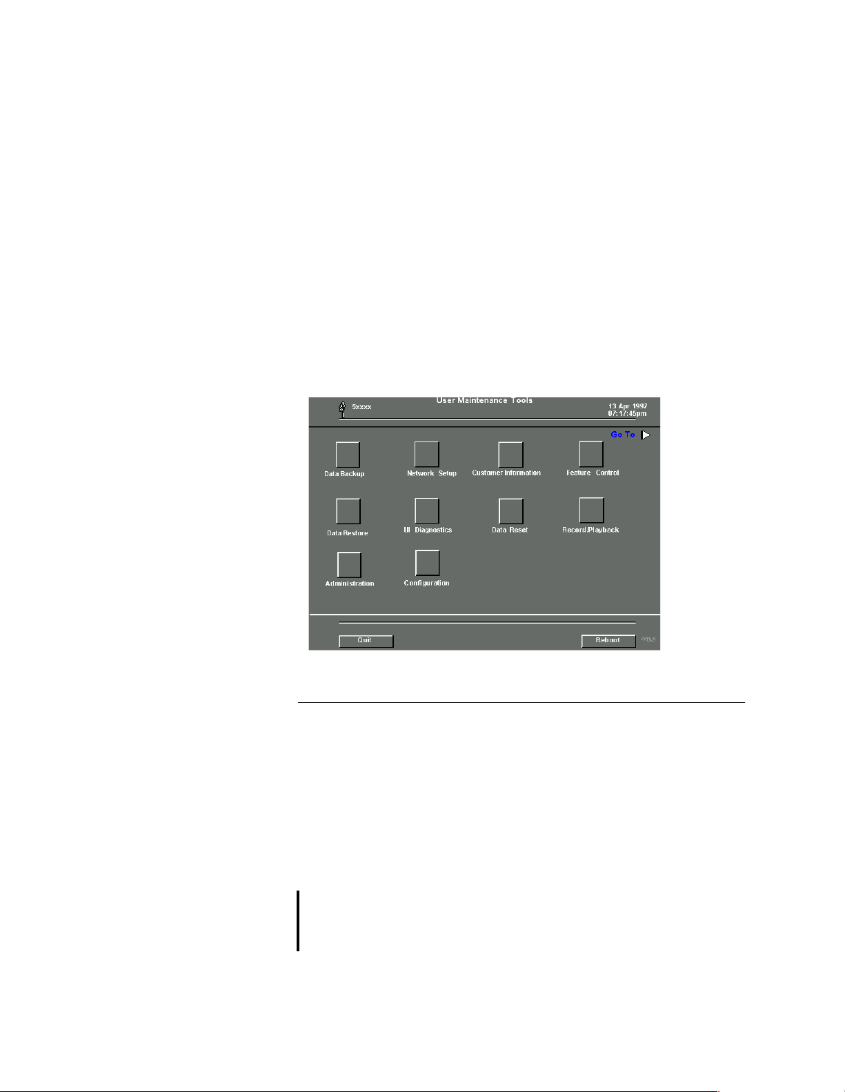
◆ To access the User Interface level:
1 Press SETUP located at the top of the Sequoi a key b oa rd. A pop up
menu appears with several options listed.
2 Use the trackball to highlight and click on the UI Service option in
the pop up menu.
A message, “
monitor. In about fifteen seconds, the User Interface Maintenance
Tools menu appears on the Sequoia video monitor. Refer to
Figure 8-1
The User Interface level of the MSM diagnostic tools has limited
capability. The Service Instructor will explain and demonstrate the
access and operation of the MSM diagnostic tools.
Starting Service Tool,” appears on the Sequoia video
.
Figure 8-1 User Interface Level Diagnostic Menu
SERVICE LEVEL Service level access is controlled with an Acuson access number and
password. Acuson access numbers and passwords are generated by
the Acuson Service Department. Sequoia access numbers are
assigned to Acuson trained service personnel by Acuson and are
unique to each person that receives them. Access numbers typically
do not change once assigned to a system or individual.
Sequoia passwords must be used in conjunction with Sequoia
access numbers to gain access to the second level (Service) of the
Sequoia MSM To ols.
NOTE: Sequoia passwords change each day for all Sequoia systems. Sequoia
Access numbers and passwords are sent to eligible service personnel
via e-mail every five to seven days.
P/N 59164 Rev. 1 Sequoia Service Training Manual Module 8- 5
Page 6

Module 8 - Diagnostic Tools Acuson Confidential
◆ To access the Service level:
1 Make sure the Sequoia system is powered off.
2 Boot to th e system:
• Hold the MULTIHERTZ® key up and the S key down
simultaneously
• Power on the system
• Hold the keys in these positions for five seconds
3 Release the MULTIHERTZ and the S keys .
4 A message, “STARTING SERVICE TOOL”, appears on the
Sequoia video monitor. Within 45 seconds, the User Interface level
diagnostic menu appears as seen in Figur e 8 -1.
5 Use the trackball to highlight and click on the ADMINISTRATION
icon of the User level diagnostic menu. A menu appears with four
different options.
6 Use the trackball to highlight and click on the “ACCESS SERVICE
LEVEL” option. A menu appears with two windows for entering
text. These two windows are for the access cod e and password.
7 Use the trackba ll to click in the access code window. Type in the
access code. Note: Any letters in the access code are to be entered in
lower case.
8 Using the trackball to click in the password window. Type in the
password. Note: Any letters in the password are to be entered in
lower case.
9 Use the trackba ll to click OK. The Service level diagnostic menu
appears.
10 Use the trackball to click PRIOR to return to the Service
Maintenance Tools menu, as shown in Figure 8-2.
NOTE: The Service Maintenance To ols menu looks similar to the User Interface
diagnostic menu except that now icons for View Logs and Hardware
Diagnostics appear.
The Service Instructor is to explain and demonstrate how to enter
an access code and password to gain access to MSM Tools.
Module 8-6 Sequoia Service Training Manual P/N 59164 Rev. 1
Page 7

Acuson Confidential Learning MSM Tools
Figure 8-2 MSM Service Level Diagnostic Menu
FRU FAULT
SOLATION TOOLS
I
Sequoia MSM Tools include a number of diagnostic capabilities to
help with FRU fault isolation in the field. These tools include:
• Sequoia system test suites
• FRU fault voting system
• Individual Circuit board test suites
• Sequoia system log files
• Three expert system tools test suites
• Sequoia system aud io test software
• Harmony system monitoring software
Along with rigorous troubleshooting and reporting processes, MSM
T ools enable service personnel to achieve fault isolation quickly and
accurately. The resulting benefits are reductions in troubleshooting
time and repeat service calls
P/N 59164 Rev. 1 Sequoia Service Training Manual Module 8- 7
Page 8

Module 8 - Diagnostic Tools Acuson Confidential
MSM Test Suites
Introduction MSM test suites are designed to achieve maximum system
diagnostic coverage in a minimal amount of time. There are three
different levels of diagnostic tests that comprise the MSM test
suites. There are no repeated or overlapping tests in any of the
suites. Each level builds upon each other to accurately determine
the cause of any failure. It is vital that lower level suites run before
higher level suites to build the proper data foundation for Sequoia’s
failure analysis software, referred to as “BRAT.”
PREFERRED STEPS TEST SUITES DIAGNOSTIC COVERAGE
Run this level first Level 1 90%
Run this level second Level 1 + Level 2 95%
Run this level third Level 1 + Level 2 + Level 3 99%
NOTE: Remember that Level 1 must always run first, then Level 2, and finally
Level 3. Running MSM test suites out of order may result in erroneous
failure data.
Additionally, note that all 3 test suites do not have to be run
consecutively to find a failure. Failures may be isolated after Level 1
runs, stops, and presents failure data. There may be no need to run
Level 2 or 3 at this point. However, to improve confidence in the Level
1 failure data, run Level 2 and 3 thereafter.
CAUTION! Shutting the Sequoia system down during or after a test suite results in
the loss of current test data. If this occurs, testing must begin with Level
1 once the system is power on again.
Module 8-8 Sequoia Service Training Manual P/N 59164 Rev. 1
Page 9

Acuson Confidential Learning MSM Tools
FAILURE ANALYSIS
V
OTING
NOTE: “BRAT” is an acronym for “Bill’s Results Analysis Tool,” taken from the
HOW DOES BRAT
W
ORK?
The MSM failure analysis voting system, referred to as “BRAT,” is
designed provide an accurate assessment of the most probable FRU
that is at fault when assessing system test failures and performance
problems.
first name of the engineer who created the failure analysis software.
The Service Instructor will explain BRAT voting results and to
demonstrate how to initiate Level 1, 2, and 3 test suites.
After each diagnostic suite is run and te st failures are detected,
BRAT software runs in the background and produces a vote which
is associated with a PCB. BRAT software requires no user
intervention.
After BRAT has run, a number is displayed next to each listed
Sequoia PCB. The PCB with the highest number next to it is most
likely the cause of a failure. This is referred to as a BRAT vote. If no
failures occur during any of the test suites (Level 1, 2, or 3), no
BRA T vote appears. BRAT software typically assigns voting
numbers ranging from 1 to 15. The higher the BRAT vote, the higher
the probability of a detected PCB failure.
SYSFAIL MESSAGES In addition to BRAT voting and pass fail test results, the Sequoia
system may display some tests results in a “Sysfail” condition. A
Sysfail message indicates that a particular test could no t be
completed due to an interdependency problem related to another
PCB. Sysfail messages can be very useful to service personnel as
they may point to the root cause of a failure, i.e. another PCB.
Sequoia PCBs use several common busse s f or communication and
work very closely together as a system. Understanding the basic
interrelationships between all Sequoia PCBs can be mo st helpful
when analyzing a Sysfail m e ssage.
Test s that result in a Sysfail condition may warrant further
investigation. Refer to the System Architecture module of this
manual to understand and interpret Sysfail messages. It may also be
necessary to discuss Sysfail messages and the most probable root
cause of a failure with Acuson Technical personnel, such as the
Acuson Help Desk.
P/N 59164 Rev. 1 Sequoia Service Training Manual Module 8- 9
Page 10

Module 8 - Diagnostic Tools Acuson Confidential
EXPERT SYSTEM TOOLS
INTRODUCTION The Expert System Tools (EST) are designed to be used in
conjunction with the information obtained by BRAT votes in the
MSM Level 1, 2, and 3 test suites. These EST tools are provided to
further refine and identify diagnostic failures. The three different
EST tools and their coverage include:
TOOL DESCRIPTION PCB DIAGNOSTIC COVERAGE DURATION
BEST Beamformer Expert System MX, TX, RX, BF, CN 7 min
PEST Processor Expert System RDP, CSD, BDM, CN 5 min
VEST Video Expert System IOV, IOE, PIC, FIZ 6 min
These tools use the concept of conditional text execution. If a
diagnostic failure shows that a particular system block is bad, the
EST does not run any further diagnostics on blocks that are
dependent on the bad block in question. This enables the EST to
develop a concise idea of which FRU is at fault. Expert System Tools
do not use the voting system that Level 1, 2 or 3 suites use. Rather,
text messages which discuss the nature of the failures found, along
with advice on which FRUs are most likely at fault appear.
BEAMFORMER
EXPERT SYSTEM
T
OOL
The Service Instructor will demonstrate how to access and initiate
Expert System Tool tests.
NOTE: For any of the Expert System Tools to run properly, Level 1 diagnostics
must be run first. Failure to do so results in erroneous EST results.
The Beamformer Expert System Tool (BEST) is helpful to service
personnel as beamformer problems can be quite confusing.
For example, under certain conditions a single channel failure test
can cause other diagnostics tests to fail erroneously. BEST focuses
strictly on the coherent beamformer section of the Sequoia system.
BEST logic is designed to help identify and isolate illu sive
beamformer failures.
◆ To initiate the BEST software:
1 Access the Service Maintenance Tools menu by entering the access
code and password, as described in “Service Level” on page 8-5.
2 Use the trackball to highlight and click on the HARDWARE
DIAGNOSTICS icon. The available hardware diagnostic test
options appear.
3 Use the trackball to highlight and click on the EXPERT SYSTEM
TOOLS option. A menu including BEST appears.
Module 8-10 Sequoia Service Training Manual P/N 59164 Rev. 1
Page 11

Acuson Confidential Expert System Tools
PROCESSOR EXPERT
S
YSTEM TOOL
◆ To initiate the PEST software:
VIDEO EXPERT SYSTEM TOOL
◆ To initiate the VEST software:
The Processor Expert System Tool (PEST) helps determine if a
failure is related to any of the systems main micro-processors. PEST
can be helpful with system wide lockups and hang-ups that aren’t
specifically implicated by other test suites such as Level 1, 2, or 3.
1 Access the Service Maintenance Too ls menu by entering the access
code and password, as described in “Service Level” on page 8-5.
2 Use the trackball to highlight and click on the HARDWARE
DIAGNOSTICS icon. The available hardware diagnostic test
options appear.
3 Use the trackball to highlight and click on the EXPERT SYSTEM
TOOLS option. A menu including PEST appears.
The Video Expert System Tool (VEST) helps isolate failures and
problems in the video pathway section of th e Se quoia DIMAQ
workstation. When dealing with problems and symptoms that
appear to be related to system video functions, running VEST may
help narrow down the possibilities of PCB’s which may be causing
a problem.
1 Access the Service Maintenance Too ls menu by entering the access
code and password, as described in “Service Level” on page 8-5.
2 Use the trackball to highlight and click on the HARDWARE
DIAGNOSTICS icon. The available hardware diagnostic test
options appear.
3 Use the trackball to highlight and click on the EXPERT SYSTEM
TOOLS option. A menu including VEST appears.
P/N 59164 Rev. 1 Sequoia Service Training Manual Module 8- 11
Page 12

Module 8 - Diagnostic Tools Acuson Confidential
INDIVIDUAL BOARD
T
EST SUITES
Individual PCB test suites are also available at the service level of
the MSM Tools. Individual PCB tests are categorized and grouped
by Sequoia PCB name. These Individual PCB test suites include all
diagnostic tests that are available for each specific PCB. Each
individual PCB test group may be run as a test suite, or tests may be
executed individually one test at a time. There is also a provision for
looping a single test or tests to aid in the iso lation of intermittent
PCB failures. Individual PCB tests suites are available for the
following Sequoi a PCBs:
• MX • RDP
• RX • CSD
• TX • IOE
• BF • IOV
• CN • PIC
• BDM
◆ To access individual PCB test suites:
1 Access the Service Maintenance Tools menu by entering the access
code and password, as described in “Service Level” on page 8-5.
2 Use the trackball to highlight and click on the HARDWARE
DIAGNOSTICS
icon. The available hardware diagnostic test
options appear.
3 Use the trackball to highlight and click on the BOARD TEST
option. A menu containing all of the individual Board Test suites
appears.
The Service Instructor will demonstrate how to access and initiate
individual board tests suites, specific individual PCB tests, and
looping PCB tests.
Module 8-12 Sequoia Service Training Manual P/N 59164 Rev. 1
Page 13

Acuson Confidential Viewing Sequoia System Logs
VIEWING SEQUOIA SYSTEM LOGS
All Sequoia systems conta in valuable system status information
stored as files on a systems’ hard disk. These hard disk files are
referred to as “Logs.” Sequoia system logs are updated frequently
by the Sequoia system operating software (OS). Sequoia log
information is maintained and retained in system files in a FIFO
manner. System logs are retained after power down, hence valuable
service information is kept for days. The amount o f ti me that
Sequoia system log data is stored varies for each log. This time is
dependent on different system conditions such as the log file size,
and the rate in which the log data is collected. In general, most logs
should contain system data for approximately three days or longer.
Sequoia system logs may be accessed at the system User Interface
(UI) or remotely via modem by Acuson Help Desk personnel.
LOCATING SYSTEM LOGS
INTERPRETING SYSTEM LOGS
◆ To locate system logs:
1 Access the Service Maintenance Too ls menu by entering the access
code and password, as described in “Service Level” on page 8-5.
2 Use the trackball to highlight and click on the VIEW LOGS
icon. The available system logs appear.
3 Use the trackba ll to highlight and click on the specific log to vi ew.
The system operating software retrieves and displays the log.
The Service Instructor will demonstrate how to access and initiate
individual board tests suites, specific individual PCB tests, and
looping PCB tests.
Certain Sequoia system logs are stored and displayed in the Sequoia
OS format. This operating system format is UNIX Lynx software.
The logs which are displayed in UNIX Lynx are:
• System Boot Log
• System Error Log
• System Installation Log
• Service User Interface Log
These logs may be difficult to interpret and understand for
individuals n ot familiar with UNIX Lynx and Sequoia soft ware. To
address this difficulty Acuson software engineers have placed a
search function at the bottom of the System Boot and Error Logs.
This search function can search an entire log for any alphanumeric
message that is entered at the Sequoia keyboard.
P/N 59164 Rev. 1 Sequoia Service Training Manual Module 8- 13
Page 14

Module 8 - Diagnostic Tools Acuson Confidential
If the system is experiencing problems, input the search terms “fatal,
kill or sleep” into the search window. If the system finds these words
contained in a log, the line of code containing it appears. The line of
software code containing any of these search terms may implicate a
specific PCB, micro-processor, or software process that has failed.
Also, input search terms for micro-processor names such as: ACP,
SSP, SDM and SMM. This type of search may also help identify
problems.
Once the search information is obtained, be sure to write it down or
photograph it if possible. When this info rmation is recorded,
discuss it with a Customer En gineer or Acuson Help Desk
personnel before ordering any parts.
COPYING A SYSTEM LOG TO A MO DISK
Sequoia system logs can be copied to a MO disk. Acuson Help Desk
personnel may request a copy of a system log or logs to assist in the
troubleshooting process. Generally, copies of logs are sent to
Acuson’s Help Desk so they can be analyzed in their entirety.
◆ To copy a log to a MO. disk:
1 Format a MO. disk by selecting the DATA BACKUP icon in the
Service Maintenance Tools menu. Insert a formatted MO disk into
the Sequoia MO disk drive.
2 Use the trackball to highlight and click the log to copy.
3 Click on COPY. The log is then copied to the MO disk.
4 Repeat to copy additional logs.
5 After the log(s) are copied, use the trackball to click on EJECT to
eject the MO disk.
SYSTEM BOOT LOG The Sequoia system boot log contains information relating to the
boot process of the Sequoia system. The boot process normally
takes place during each power up cycle, or during the reboot
command generated from the Service level of the MSM Tools menu.
The boot log contains information on Power Up Test results (PUT
Test s), system micro-processor start-up
status, and various other OS sof tware conditions. System boot log
data can help troubleshoot an intermittent problem or a down
system.
The Service Instructor will demonstrate how to access and interpret
system boot log data.
Module 8-14 Sequoia Service Training Manual P/N 59164 Rev. 1
Page 15

Acuson Confidential Viewing Sequoia System Logs
HARDWARE
D
IAGNOSTIC
SUMMARY LOG
HARDWARE
DIAGNOSTIC DETAIL
OG
L
The Hardware Diagn ost ic Summary log sto res system hardware
configuration information and records the basic results of
diagnostic tests that have be e n run. The system hardware
configuration data in this log includes: PCB slot name, PCB part
name, PCB revision level, PCB part number, and PCB serial number.
The diagnostic test results stored in this log includes the test
numbers of diagnostic tests run and the pass / fail status of these
tests.
The Service Instructor will demonstrate how to access and interpret
the Hardware Diagnostic Summary Log.
The Hardware Diagnostic Detail log contains the same information
as the Hardware Diagnostic Summary Log except with greater
detail. The PCB slot name, PCB part name, PCB revision level, PCB
part number , a nd PCB serial number appear just as in the Hardw are
Diagnostic Summary Log. However, test results appear with more
detailed information. Test failure details are displayed in the UNIX
Lynx system operating code.
In addition , BRAT votes are also stored and displayed, should any
be logged during Level 1, 2, or 3 test suites.
The Service Instructor will demonstrate how to access and interpret
the Hardware Diagnostic Detail Log data.
SEQUOIA ERROR LOG
The Sequoia Error log actually contain s two logs:
• System Error log. The System Error log is a list of chronological
events that describe the system status. Information such as
power up, power down, time duration, hard disk status, stack
information, and hardware error events appear.
• Software Activity log plus Software Error log. The Software
Activity log and Software Error log provide a chronological
report on activities such as software power up commands, key
stroke commands sent to software code, messaging for errors,
and messaging for software warnings.
The Service Instructor will demonstrate how to access and interpret
Sequoia Error Log data.
P/N 59164 Rev. 1 Sequoia Service Training Manual Module 8- 15
Page 16

Module 8 - Diagnostic Tools Acuson Confidential
HARMONY LOG
I
NTERPRETATION
Harmony refers to th e specialized hardware and software that
monitors Sequoia power supplies, internal card cage air
temperature, PCB fuse status, AC input voltage, and power supply
noise levels. The name Harmony is derived from the Acuson term
Hardware Monitor. Harmon y hardware res ides on the PIC board
while harmony software and harmony logs reside on the hard
drive. Harmony software sampl e s harmony hardware signals
approximately every ten minutes while the system is powered up.
These readings are stored in a harmony log each time they are
measured. The harmony log contains past and present information
on power supplies, internal air temp, power supply noise, and AC
input voltages, which is quite useful to service personnel.
◆ To locate a harmony log:
1 Access the Service Maintenance Tools menu by entering the access
code and password, as described in “Service Level” on page 8-5.
2 Use the trackball to highlight and click on the VIEW LOGS
icon. The available system logs appear.
3 Use the trackball to highlight and click on the HARMONY LOG.
The system operating software retrieves and displays the log.
The Service Instructor will demonstrate how to access and interpret
Harmony Log data.
POWER UP TESTS
OG
L
Power Up Tests (PUT) check Sequoia system hardware each time a
system is powered up or rebooted. Power Up Tests appear on a
Sequoia video monitor if they fail during a power on or reboot
cycle. The Power Up Test Log stores any PUT failures that occur
during power up or reboot sequences. If a PUT error occurs, and a
Sequoia operator fails to record it, the PUT log can be accessed by
Service Personnel to determine which PUT failures have occurred.
Each PUT is assigned a number typically ranging from 1 to 30. Each
PUT is different and tests different blocks of hardware throughout
the Sequoia system. To obtain further data on a specific PUT test,
refer to the MSM User’s Guide provided along with this Sequoia
Training Manual.
The Service Instructor will demonstrate how to access the PUT Log
data.
Module 8-16 Sequoia Service Training Manual P/N 59164 Rev. 1
Page 17

Acuson Confidential Worksheet: MSM Tools
WORKSHEET: MSM TOOLS
LAB OBJECTIVE NOTES SIGN OFF
P/N 59164 Rev. 1 Sequoia Service Training Manual Module 8- 17
Page 18

Module 8 - Diagnostic Tools Acuson Confidential
Module 8-18 Sequoia Service Training Manual P/N 59164 Rev. 1
 Loading...