

Page 1
12Replacing RM Module
12.1Overview
The replacement RM Module does not include the Hard Disk Drive (HDD). The HDD must be removed from
the existing RM Module and installed into the replacement RM Module.
12.1.1Workflow
12.1.2Required Material
ACUSON S Family
System
Replacement Instructions
Parts Replacement
This document is valid for:
ACUSON S1000 Ultrasound Systems
ACUSON S2000 Ultrasound Systems
ACUSON S3000 Ultrasound Systems
US22-101.841.01.19.02 | 04.22
Remove the Upper Covers
01
Remove the E Module Cover
02
Remove the RM Module
03
Remove the HDD
04
Install the HDD in the new RM Module
05
Install the RM Module
06
Install the E Module Cover
07
Install the Upper Covers
08
Verification
09
RM Module (Refer to the Service Parts Catalog)
Tie-Wraps
21.08.24, 11:47
ACUSON S3000
localhost:3006/#/documents/US22-101.841.01.XX.02.json?fragment=%2FUS22-101.841.01.XX.02.d3ff9f51462ebbea0a53dbda7dfa389b.html&s…
1/33
Page 2
12.1.3Required Tools
12.1.4Required Time
Approximately one (1) hour.
12.1.5System Preparation
i
There are several RM Module versions with different BIOS settings. Replacing RM
Modules will require booting to a new version of software. Refer to Table below.
Material Number Name BIOS Version
Minimum
Software
Requirement
10438526 RM300, CPU Module, S2000/VI 5893 or 5893V2 VB10D
10852163 RM300 Module w/o HDD, BIOS
5936
5936 VC20A
10855525 RM300 Mod w/o
HD/BIOS5936/GT640/403
5936 VC25C
10854302 RM300 Module w/o HDD, BIOS
5936, GT640
5936 VC25C
10854750 RM301, CPU Module, w/o HDD, F1.13 VC25D
Standard CSE tool kit
Service Key
Press the Power button on the Control Panel and follow the instructions on the screen to shut down
the system.
01
Click Shutdown to shut down the system.
02
Switch the MAIN circuit breaker to the Off position.
03
Disconnect the system power cord from its external power source.
04
Maintain a minimum of 3.5 feet (1 meter) clearance while working on the system.
05
CAUTION
Leakage tests must be performed after replacing electrical components connected to nonisolated AC power.
Failure to complete a leakage test may result in damage to the system.
21.08.24, 11:47
ACUSON S3000
localhost:3006/#/documents/US22-101.841.01.XX.02.json?fragment=%2FUS22-101.841.01.XX.02.d3ff9f51462ebbea0a53dbda7dfa389b.html&s…
2/33
Page 3
Material Number Name BIOS Version
Minimum
Software
Requirement
S Family
Tab.1:RM300 Module Hardware/Software Matrix
12.2RM Module and Hard Disk Drive (HDD)
Instructions
12.2.1Remove the Upper Covers
Remove the covers in the order they are listed in this procedure.
12.2.2Remove the E Module Cover
There are two (2) different E Module Covers:
Remove the transducers from the system.
01
Remove the upper, left-front cover. Reference 9.2.1.2Remove the Upper, Left-Front Cover for
instructions.
02
Remove the upper, right-front cover. Reference 9.2.1.3Remove the Upper, Right-Front Cover for
instructions.
03
Remove the system air filter. Reference 9.2.1.1Remove the System Air Filter for instructions.
04
Remove the storage bin cover. Reference 9.2.1.4Remove the Storage Bin Cover for instructions.
05
Remove any OEM cables connected to the system and feed them through the left-rear cover.
06
Remove the upper, right-rear cover. Reference 9.2.1.5Remove the Upper, Right-Rear Cover for
instructions.
07
Remove the upper, left-rear cover. Reference 9.2.1.6Remove the Upper, Left-Rear Cover for
instructions.
08
Remove the E-Module OEM Support Bracket.
09
CAUTION
The system contains components that are sensitive to damage by electrostatic discharge (ESD).
Observe all ESD protective procedures and use ESD protective equipment including an ESD
wrist strap when the protective covers are removed from the system.
The older version has a Cable Tray and Captive screws.
The newer version has Cable Clips and non-captive screws.
21.08.24, 11:47
ACUSON S3000
localhost:3006/#/documents/US22-101.841.01.XX.02.json?fragment=%2FUS22-101.841.01.XX.02.d3ff9f51462ebbea0a53dbda7dfa389b.html&s…
3/33
Page 4
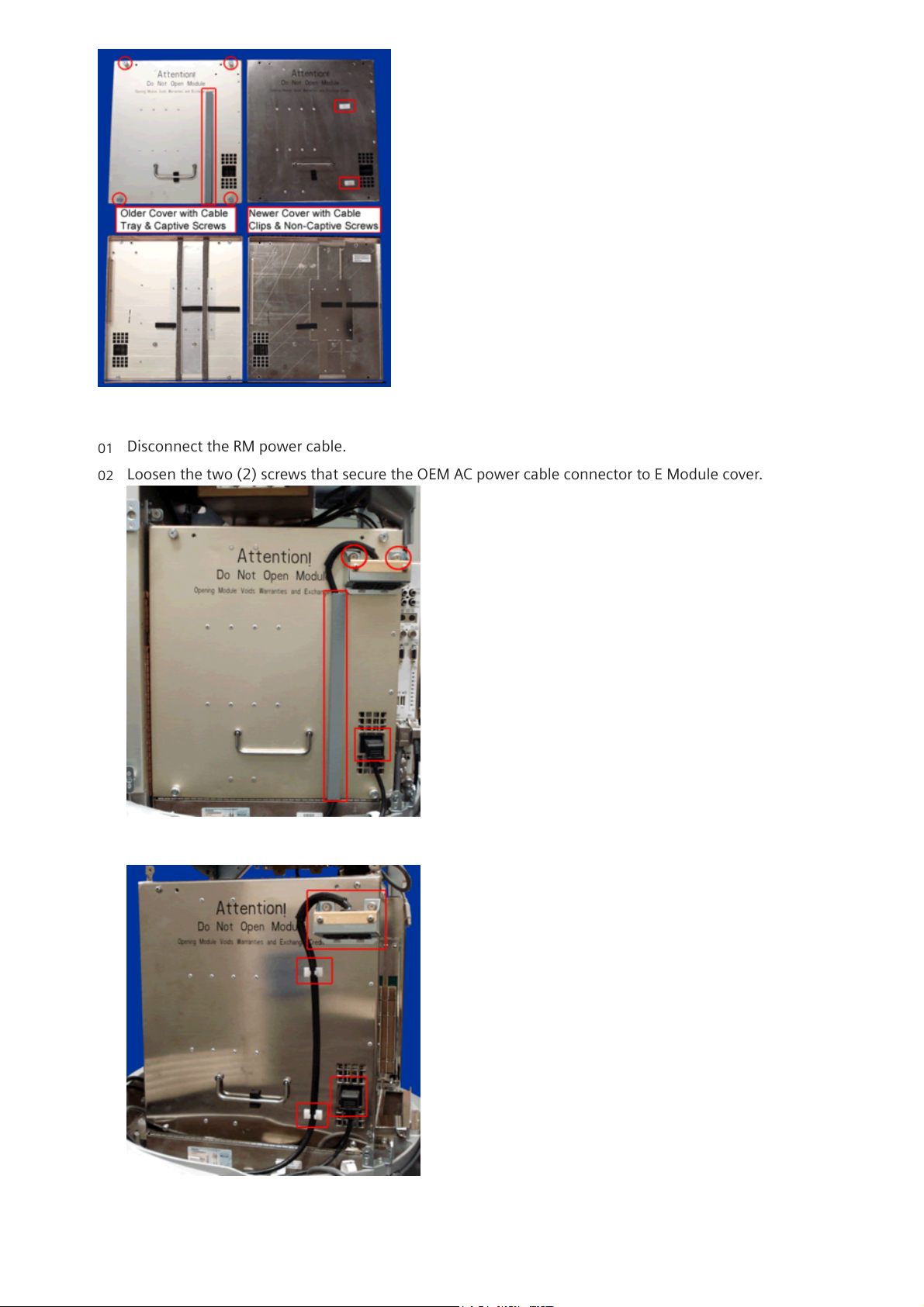
Fig.177:E Module Cover Versions
Disconnect the RM power cable.
01
Loosen the two (2) screws that secure the OEM AC power cable connector to E Module cover.
Fig.178:Older E Module Cover -- OEM AC Cable Connector and RM Power Cable
Fig.179:Newer E Module Cover -- OEM AC Cable Connector and RM Power Cable
02
21.08.24, 11:47
ACUSON S3000
localhost:3006/#/documents/US22-101.841.01.XX.02.json?fragment=%2FUS22-101.841.01.XX.02.d3ff9f51462ebbea0a53dbda7dfa389b.html&s…
4/33
Page 5
Depending upon the E Module cover, remove the cable from the cable clips, or remove the cable tray
cover and then remove the cable.
i
Newer E Module covers will have cable clips instead of a cable tray.
03
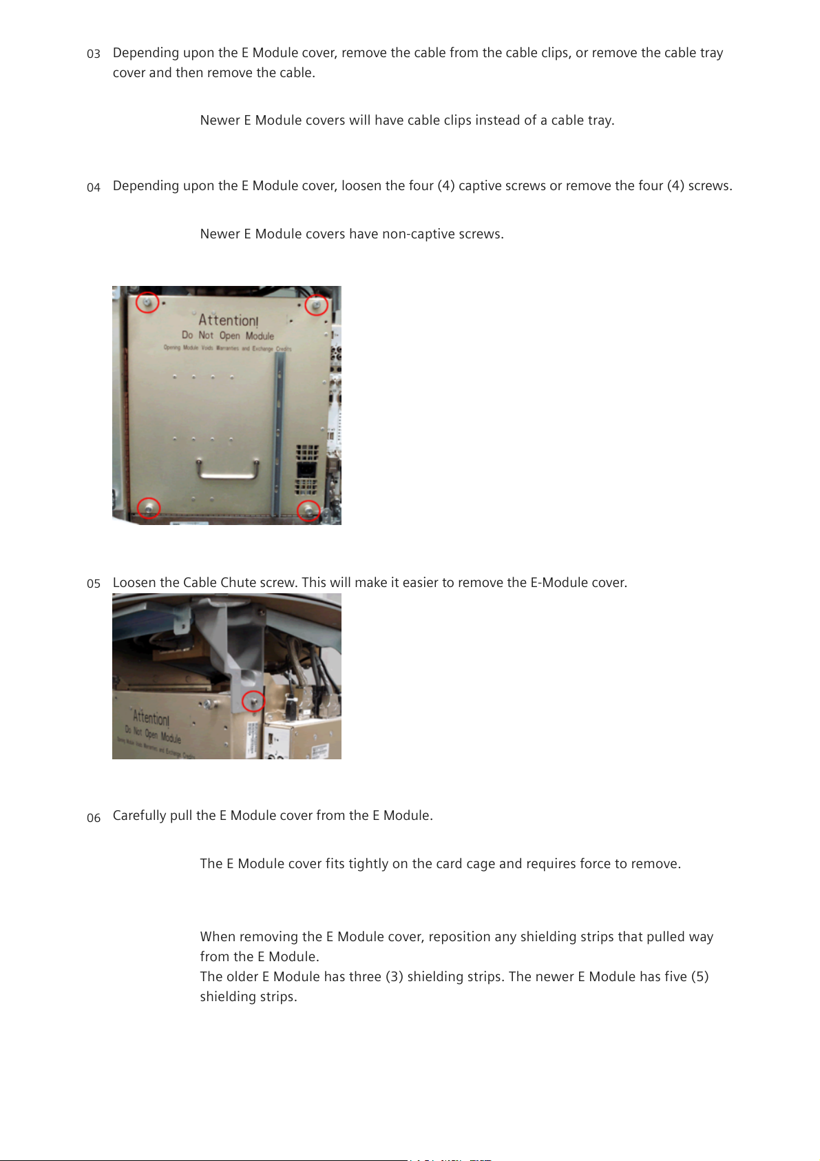
Depending upon the E Module cover, loosen the four (4) captive screws or remove the four (4) screws.
i
Newer E Module covers have non-captive screws.
Fig.180:E Module Cover -- Screws
04
Loosen the Cable Chute screw. This will make it easier to remove the E-Module cover.
Fig.181:Cable Chute Screw
05
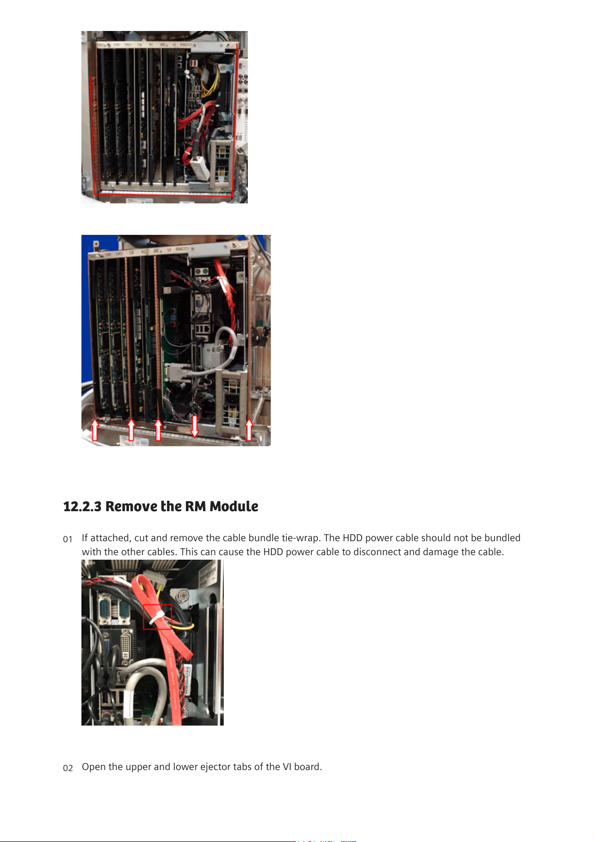
Carefully pull the E Module cover from the E Module.
i
The E Module cover fits tightly on the card cage and requires force to remove.
i
When removing the E Module cover, reposition any shielding strips that pulled way
from the E Module.
The older E Module has three (3) shielding strips. The newer E Module has five (5)
shielding strips.
06
21.08.24, 11:47
ACUSON S3000
localhost:3006/#/documents/US22-101.841.01.XX.02.json?fragment=%2FUS22-101.841.01.XX.02.d3ff9f51462ebbea0a53dbda7dfa389b.html&s…
5/33
Page 6
12.2.3Remove the RM Module
Fig.182:Older E Module with Three (3) Shielding Strips
Fig.183:Newer E Module with Five (5) Shielding Strips
If attached, cut and remove the cable bundle tie-wrap. The HDD power cable should not be bundled
with the other cables. This can cause the HDD power cable to disconnect and damage the cable.
Fig.184:HDD Cables Bundled with Tie-Wrap
01
Open the upper and lower ejector tabs of the VI board.
02
21.08.24, 11:47
ACUSON S3000
localhost:3006/#/documents/US22-101.841.01.XX.02.json?fragment=%2FUS22-101.841.01.XX.02.d3ff9f51462ebbea0a53dbda7dfa389b.html&s…
6/33
Page 7
Pull the VI board approximately one-inch out from the card cage to gain access to the VI Board
connectors.
03
Carefully disconnect the VI board connections (P is the RM cable connector, J is the VI board
connector):
04
P10 - J10 (RM200 Only)
P11 - J11
P13 - J13
P16 - J16
P12 - J12
P17-- J17
P18 – J18
P21 -- J21
RS232 Ribbon Cable (RM 200 Only)
DVI Video Cable
Carefully disconnect the following RM connections:
i
The Line In (Blue) audio cable is not used with the RM 301 Module.
05
Audio cables, labeled: Line In (Blue); Line Out (Green); Mic (Pink)
Two USB cables: USB 0, USB 1
Assy, PCI-e Cable (J7)
DVI Video Cable
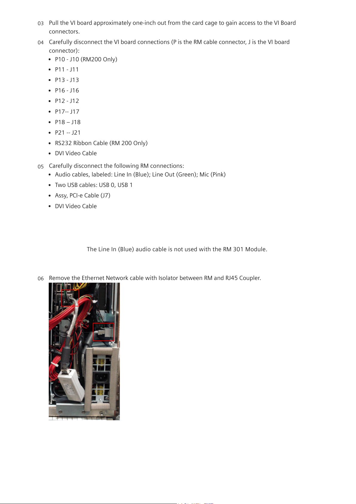
Remove the Ethernet Network cable with Isolator between RM and RJ45 Coupler.
Fig.185:Ethernet Cable with Isolator
06
21.08.24, 11:47
ACUSON S3000
localhost:3006/#/documents/US22-101.841.01.XX.02.json?fragment=%2FUS22-101.841.01.XX.02.d3ff9f51462ebbea0a53dbda7dfa389b.html&s…
7/33
Page 8
12.2.4Remove the Hard Disk Drive
i
The RM300 requires two (2) Ethernet Cables with the Isolator. The RM301 only uses
one (1) Ethernet Cable and does not require the Isolator.
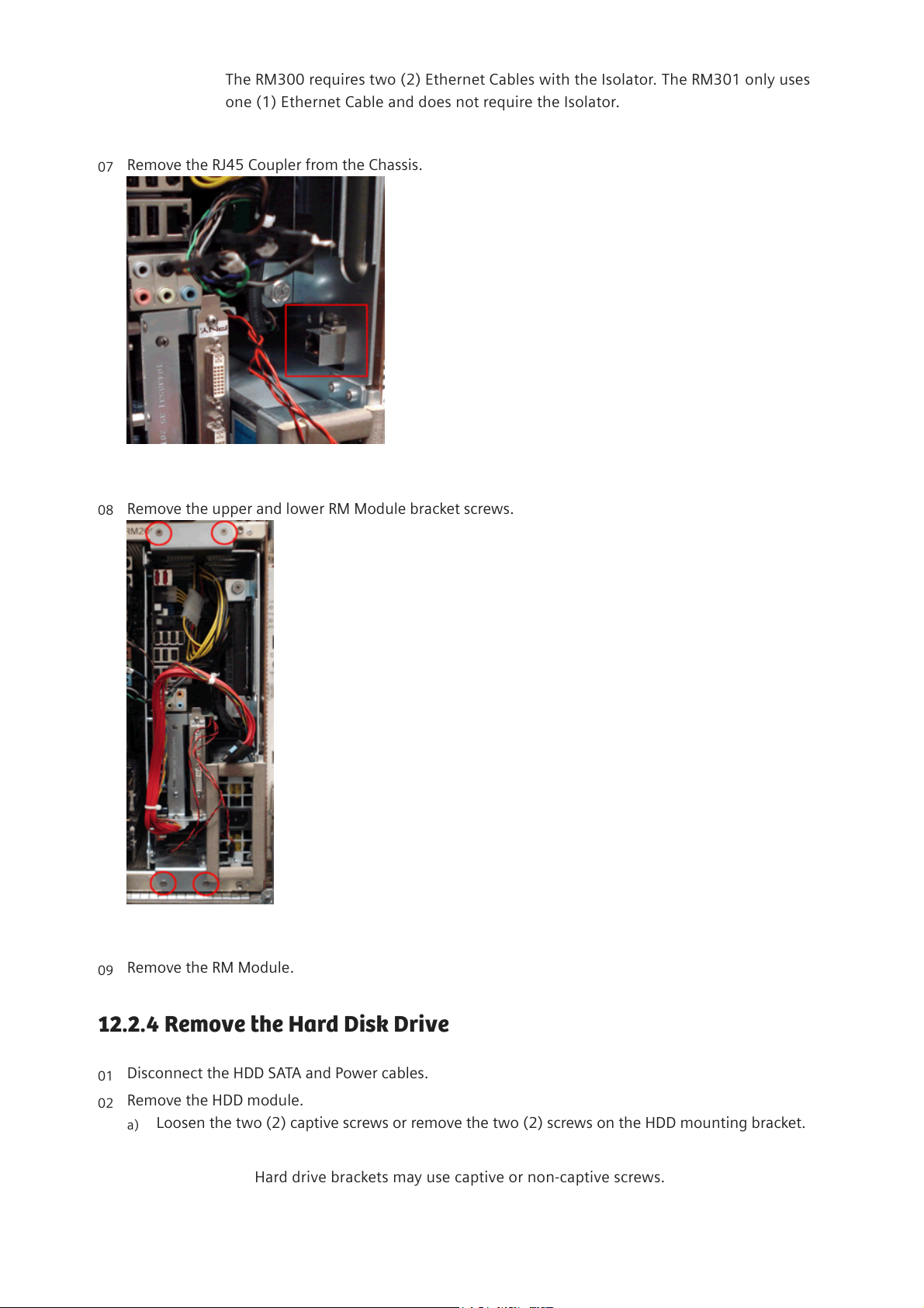
Remove the RJ45 Coupler from the Chassis.
Fig.186:RJ45 Coupler
07
Remove the upper and lower RM Module bracket screws.
Fig.187:RM200 Module Bracket Screws
08
Remove the RM Module.
09
Disconnect the HDD SATA and Power cables.
01
Remove the HDD module.
02
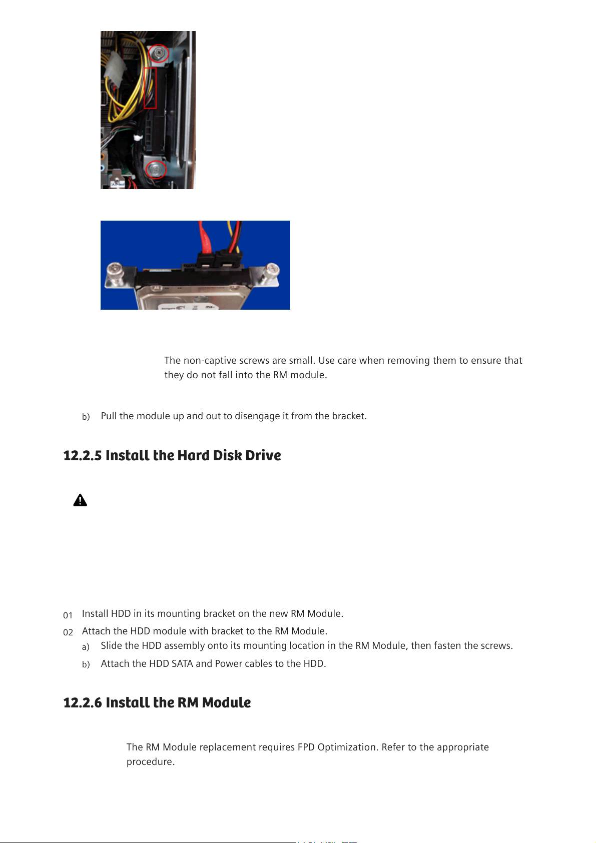
Loosen the two (2) captive screws or remove the two (2) screws on the HDD mounting bracket.
i
Hard drive brackets may use captive or non-captive screws.
a)
21.08.24, 11:47
ACUSON S3000
localhost:3006/#/documents/US22-101.841.01.XX.02.json?fragment=%2FUS22-101.841.01.XX.02.d3ff9f51462ebbea0a53dbda7dfa389b.html&s…
8/33
Page 9
12.2.5Install the Hard Disk Drive
12.2.6Install the RM Module
i
The RM Module replacement requires FPD Optimization. Refer to the appropriate
procedure.
Fig.188:HDD Bracket Screws
Fig.189:HDD SATA and Power Connections
i
The non-captive screws are small. Use care when removing them to ensure that
they do not fall into the RM module.
Pull the module up and out to disengage it from the bracket.
b)
CAUTION
The system contains components that are sensitive to damage by electrostatic discharge (ESD).
Observe all ESD protective procedures and use ESD protective equipment including an ESD
wrist strap when the protective covers are removed from the system.
Install HDD in its mounting bracket on the new RM Module.
01
Attach the HDD module with bracket to the RM Module.
02
Slide the HDD assembly onto its mounting location in the RM Module, then fasten the screws.
a)
Attach the HDD SATA and Power cables to the HDD.
b)
21.08.24, 11:47
ACUSON S3000
localhost:3006/#/documents/US22-101.841.01.XX.02.json?fragment=%2FUS22-101.841.01.XX.02.d3ff9f51462ebbea0a53dbda7dfa389b.html&s…
9/33
Page 10
i
RM Module Replacement requires that the field electrical safety test be performed. Refer
to General Field Electrical Safety Test Procedure / US00-004.860.01 or Field Electrical
Safety Test Procedure / US00-003.860.01 for the procedure, and to Electrical Safety
Limits / US22-101.833.01 for limits.
Slide the RM Module into the RM slot in the card cage.
01
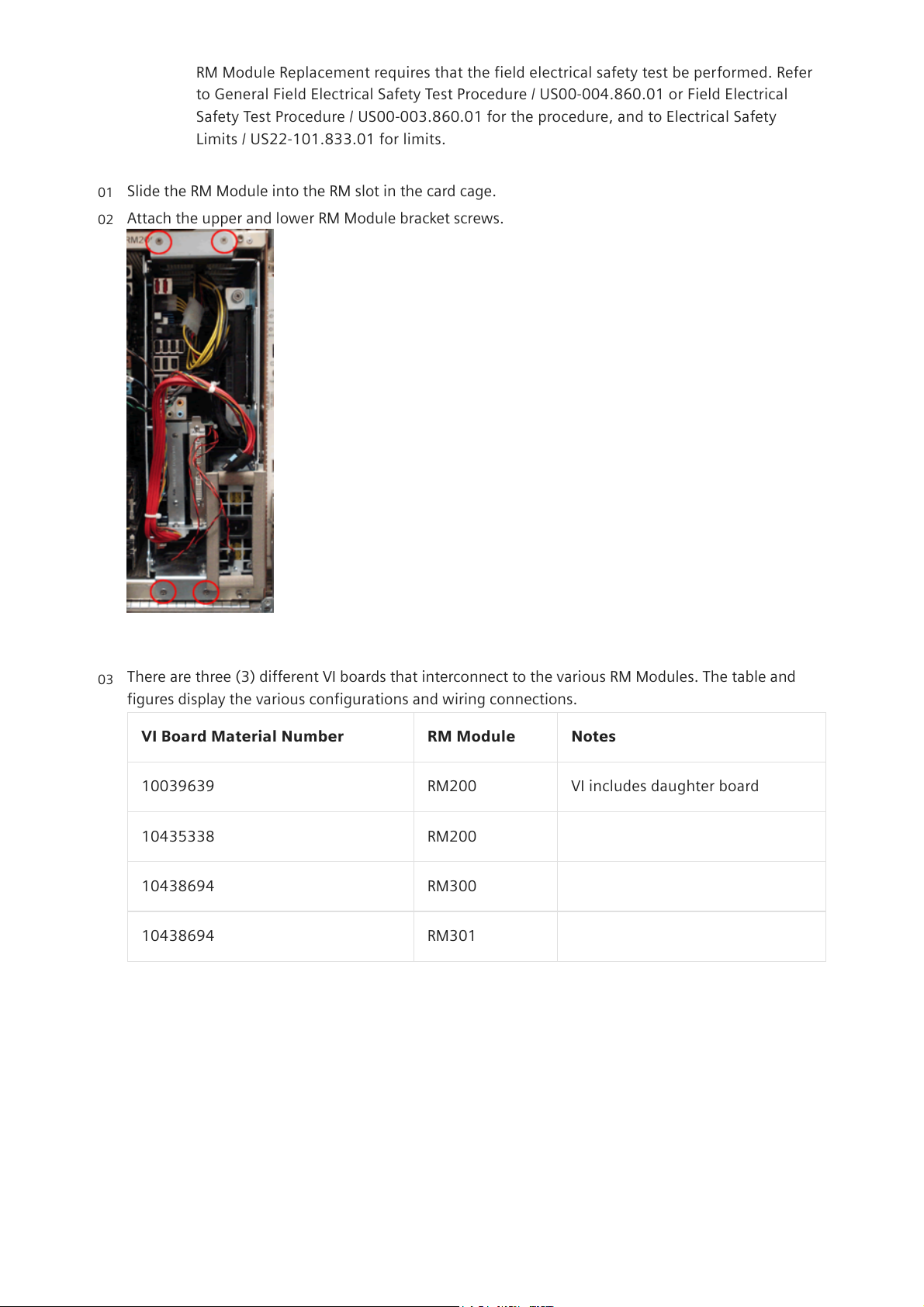
Attach the upper and lower RM Module bracket screws.
Fig.190:RM Module Screws
02
There are three (3) different VI boards that interconnect to the various RM Modules. The table and
figures display the various configurations and wiring connections.
VI Board Material Number RM Module Notes
10039639 RM200 VI includes daughter board
10435338 RM200
10438694 RM300
10438694 RM301
Tab.2:VI Board to RM Module Configuration
03
21.08.24, 11:47
ACUSON S3000
localhost:3006/#/documents/US22-101.841.01.XX.02.json?fragment=%2FUS22-101.841.01.XX.02.d3ff9f51462ebbea0a53dbda7dfa389b.html&…
10/33
Page 11
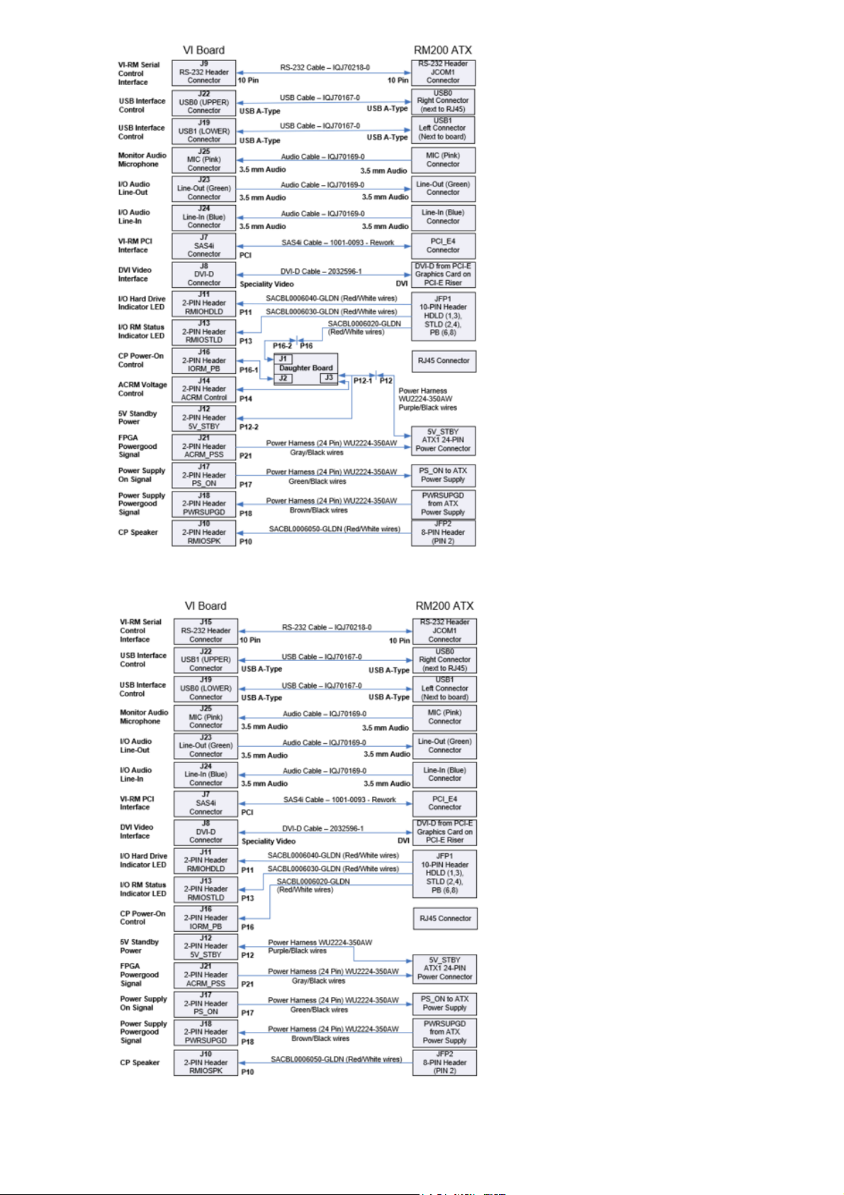
Fig.191:VI Board Material Number 10039639 to RM200 Module
Fig.192:VI Board Material Number 10435338 to RM200 Module
21.08.24, 11:47
ACUSON S3000
localhost:3006/#/documents/US22-101.841.01.XX.02.json?fragment=%2FUS22-101.841.01.XX.02.d3ff9f51462ebbea0a53dbda7dfa389b.html&…
11/33
Page 12
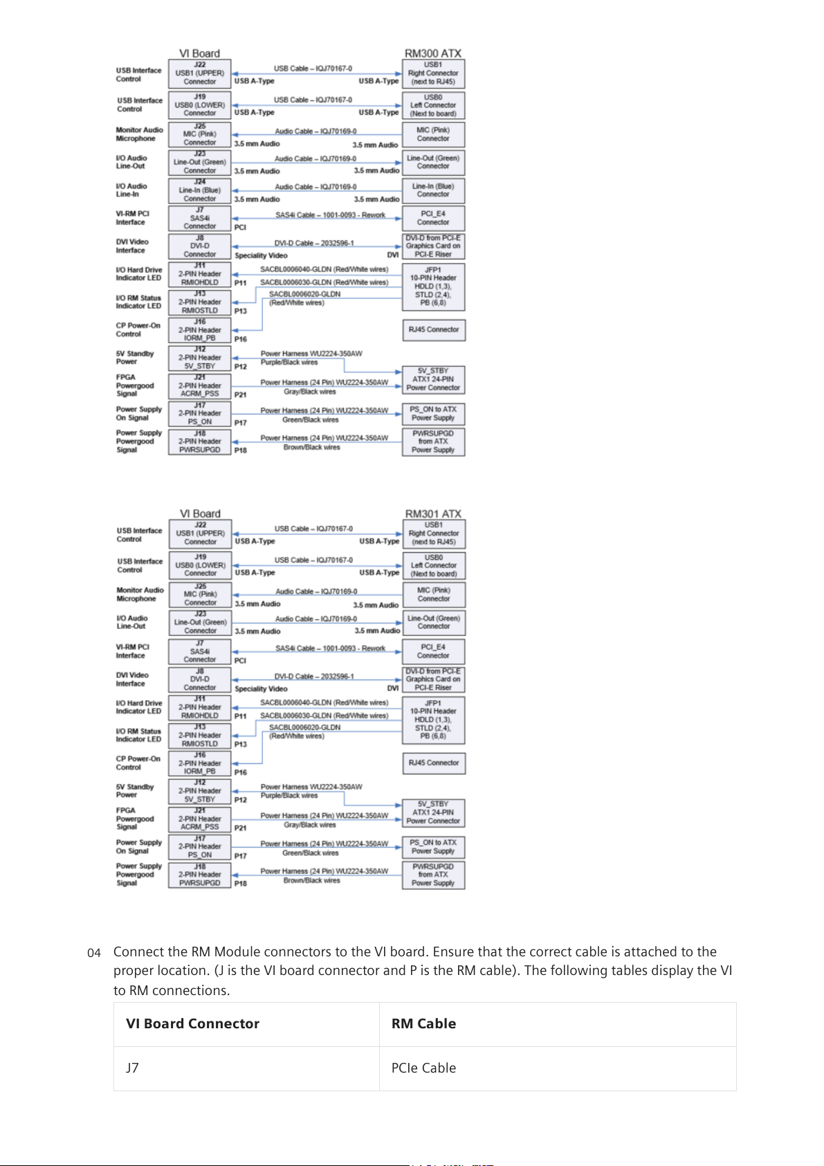
Fig.193:VI Board Material Number 10438694 to RM300 Module
Fig.194:VI Board Material Number 10438694 to RM301 Module
Connect the RM Module connectors to the VI board. Ensure that the correct cable is attached to the
proper location. (J is the VI board connector and P is the RM cable). The following tables display the VI
to RM connections.
VI Board Connector RM Cable
J7 PCIe Cable
04
21.08.24, 11:47
ACUSON S3000
localhost:3006/#/documents/US22-101.841.01.XX.02.json?fragment=%2FUS22-101.841.01.XX.02.d3ff9f51462ebbea0a53dbda7dfa389b.html&…
12/33
Page 13
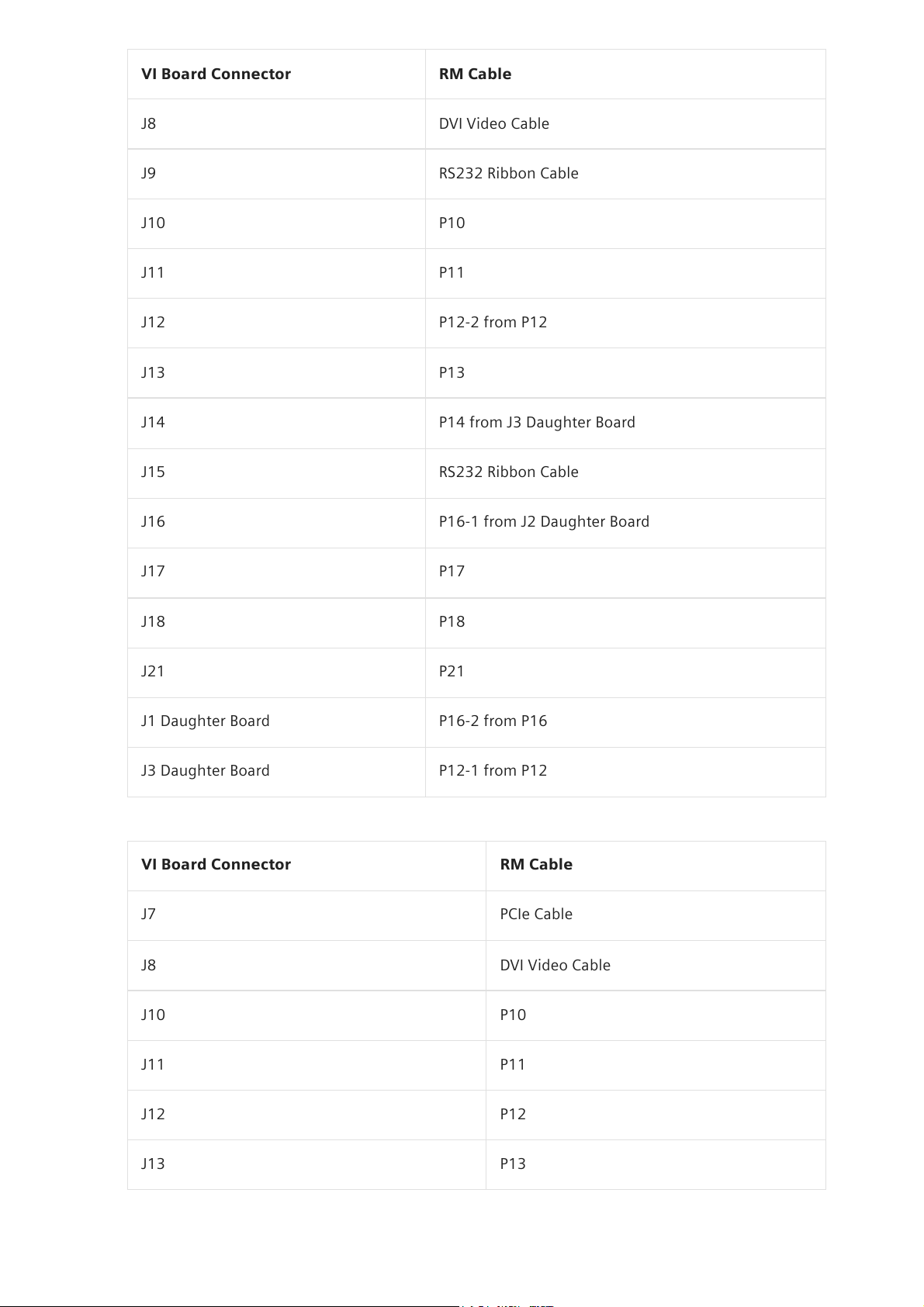
VI Board Connector RM Cable
J8 DVI Video Cable
J9 RS232 Ribbon Cable
J10 P10
J11 P11
J12 P12-2 from P12
J13 P13
J14 P14 from J3 Daughter Board
J15 RS232 Ribbon Cable
J16 P16-1 from J2 Daughter Board
J17 P17
J18 P18
J21 P21
J1 Daughter Board P16-2 from P16
J3 Daughter Board P12-1 from P12
Tab.3:VI Board (10039639) Connector to RM 200 Module
VI Board Connector RM Cable
J7 PCIe Cable
J8 DVI Video Cable
J10 P10
J11 P11
J12 P12
J13 P13
21.08.24, 11:47
ACUSON S3000
localhost:3006/#/documents/US22-101.841.01.XX.02.json?fragment=%2FUS22-101.841.01.XX.02.d3ff9f51462ebbea0a53dbda7dfa389b.html&…
13/33
Page 14
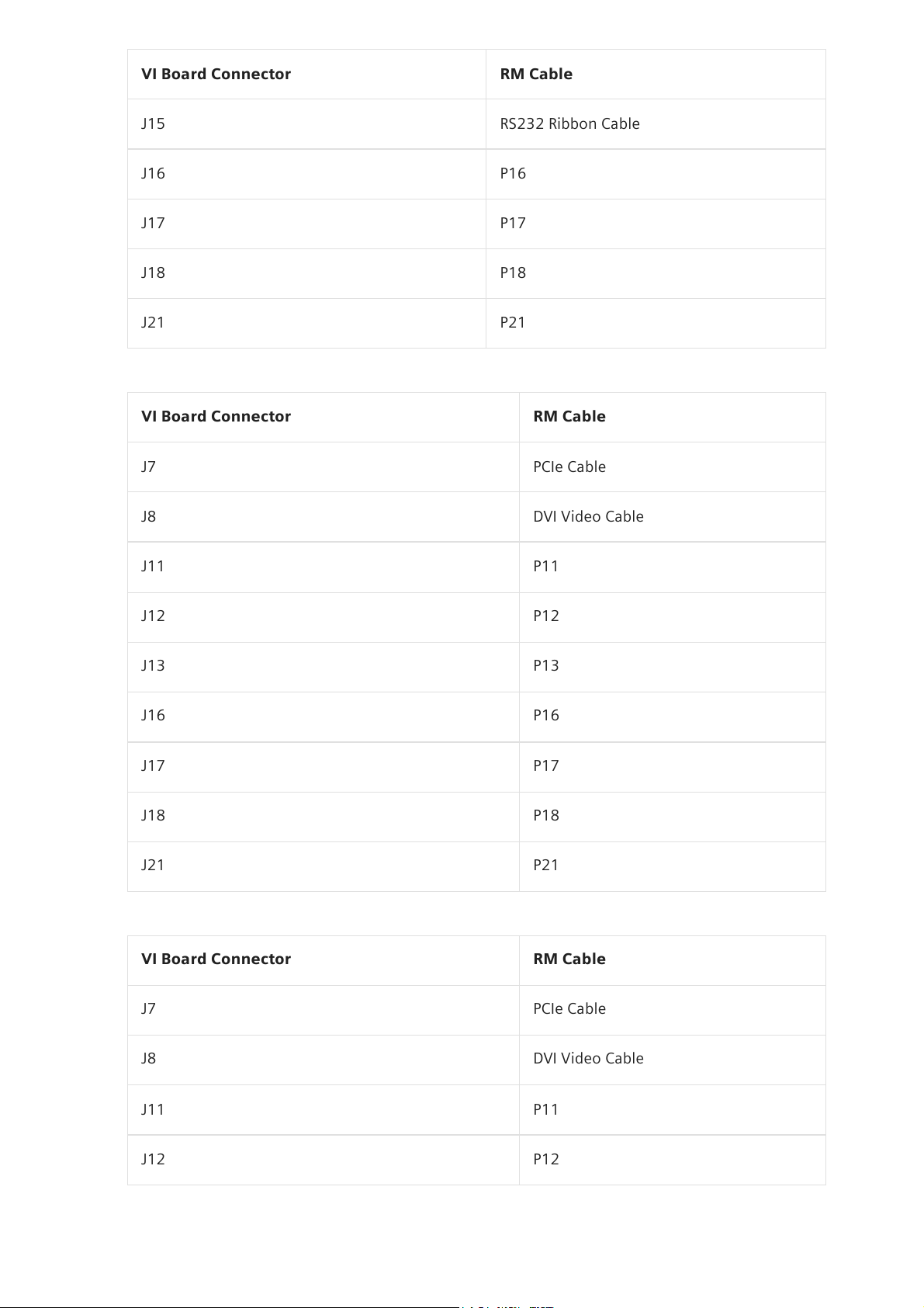
VI Board Connector RM Cable
J15 RS232 Ribbon Cable
J16 P16
J17 P17
J18 P18
J21 P21
Tab.4:VI Board (10435338) Connector to RM 200 Module
VI Board Connector RM Cable
J7 PCIe Cable
J8 DVI Video Cable
J11 P11
J12 P12
J13 P13
J16 P16
J17 P17
J18 P18
J21 P21
Tab.5:VI Board (10438694) Connector to RM 300 Module
VI Board Connector RM Cable
J7 PCIe Cable
J8 DVI Video Cable
J11 P11
J12 P12
21.08.24, 11:47
ACUSON S3000
localhost:3006/#/documents/US22-101.841.01.XX.02.json?fragment=%2FUS22-101.841.01.XX.02.d3ff9f51462ebbea0a53dbda7dfa389b.html&…
14/33
Page 15
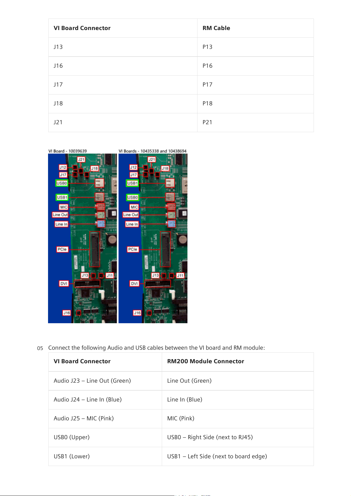
VI Board Connector RM Cable
J13 P13
J16 P16
J17 P17
J18 P18
J21 P21
Tab.6:VI Board (10438694) Connector to RM 301 Module
Fig.195:VI Board Connections
Connect the following Audio and USB cables between the VI board and RM module:
VI Board Connector RM200 Module Connector
Audio J23 – Line Out (Green) Line Out (Green)
Audio J24 – Line In (Blue) Line In (Blue)
Audio J25 – MIC (Pink) MIC (Pink)
USB0 (Upper) USB0 – Right Side (next to RJ45)
USB1 (Lower) USB1 – Left Side (next to board edge)
05
21.08.24, 11:47
ACUSON S3000
localhost:3006/#/documents/US22-101.841.01.XX.02.json?fragment=%2FUS22-101.841.01.XX.02.d3ff9f51462ebbea0a53dbda7dfa389b.html&…
15/33
Page 16
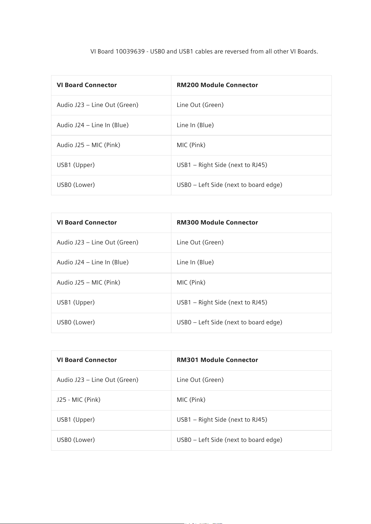
Tab.7:VI Board 10039639 to RM200 Module
i
VI Board 10039639 - USB0 and USB1 cables are reversed from all other VI Boards.
VI Board Connector RM200 Module Connector
Audio J23 – Line Out (Green) Line Out (Green)
Audio J24 – Line In (Blue) Line In (Blue)
Audio J25 – MIC (Pink) MIC (Pink)
USB1 (Upper) USB1 – Right Side (next to RJ45)
USB0 (Lower) USB0 – Left Side (next to board edge)
Tab.8:VI Board 10435338 to RM200 Module
VI Board Connector RM300 Module Connector
Audio J23 – Line Out (Green) Line Out (Green)
Audio J24 – Line In (Blue) Line In (Blue)
Audio J25 – MIC (Pink) MIC (Pink)
USB1 (Upper) USB1 – Right Side (next to RJ45)
USB0 (Lower) USB0 – Left Side (next to board edge)
Tab.9:VI Board 10438694 to RM300 Module
VI Board Connector RM301 Module Connector
Audio J23 – Line Out (Green) Line Out (Green)
J25 - MIC (Pink) MIC (Pink)
USB1 (Upper) USB1 – Right Side (next to RJ45)
USB0 (Lower) USB0 – Left Side (next to board edge)
Tab.10:VI Board 10438694 to RM301 Module
21.08.24, 11:47
ACUSON S3000
localhost:3006/#/documents/US22-101.841.01.XX.02.json?fragment=%2FUS22-101.841.01.XX.02.d3ff9f51462ebbea0a53dbda7dfa389b.html&…
16/33
Page 17
i
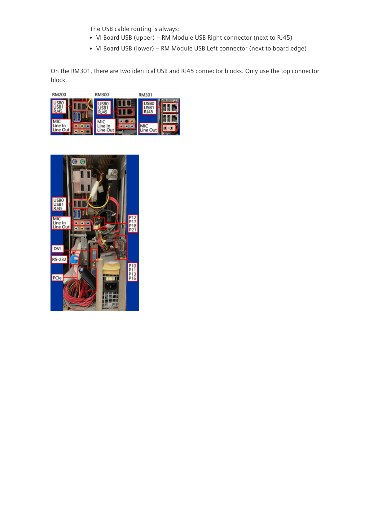
The USB cable routing is always:
On the RM301, there are two identical USB and RJ45 connector blocks. Only use the top connector
block.
Fig.196:RM Module USB, RJ45 Network Jack, and Audio Cable Connections
Fig.197:RM200 Cables and Connections
VI Board USB (upper) – RM Module USB Right connector (next to RJ45)
VI Board USB (lower) – RM Module USB Left connector (next to board edge)
21.08.24, 11:47
ACUSON S3000
localhost:3006/#/documents/US22-101.841.01.XX.02.json?fragment=%2FUS22-101.841.01.XX.02.d3ff9f51462ebbea0a53dbda7dfa389b.html&…
17/33
Page 18
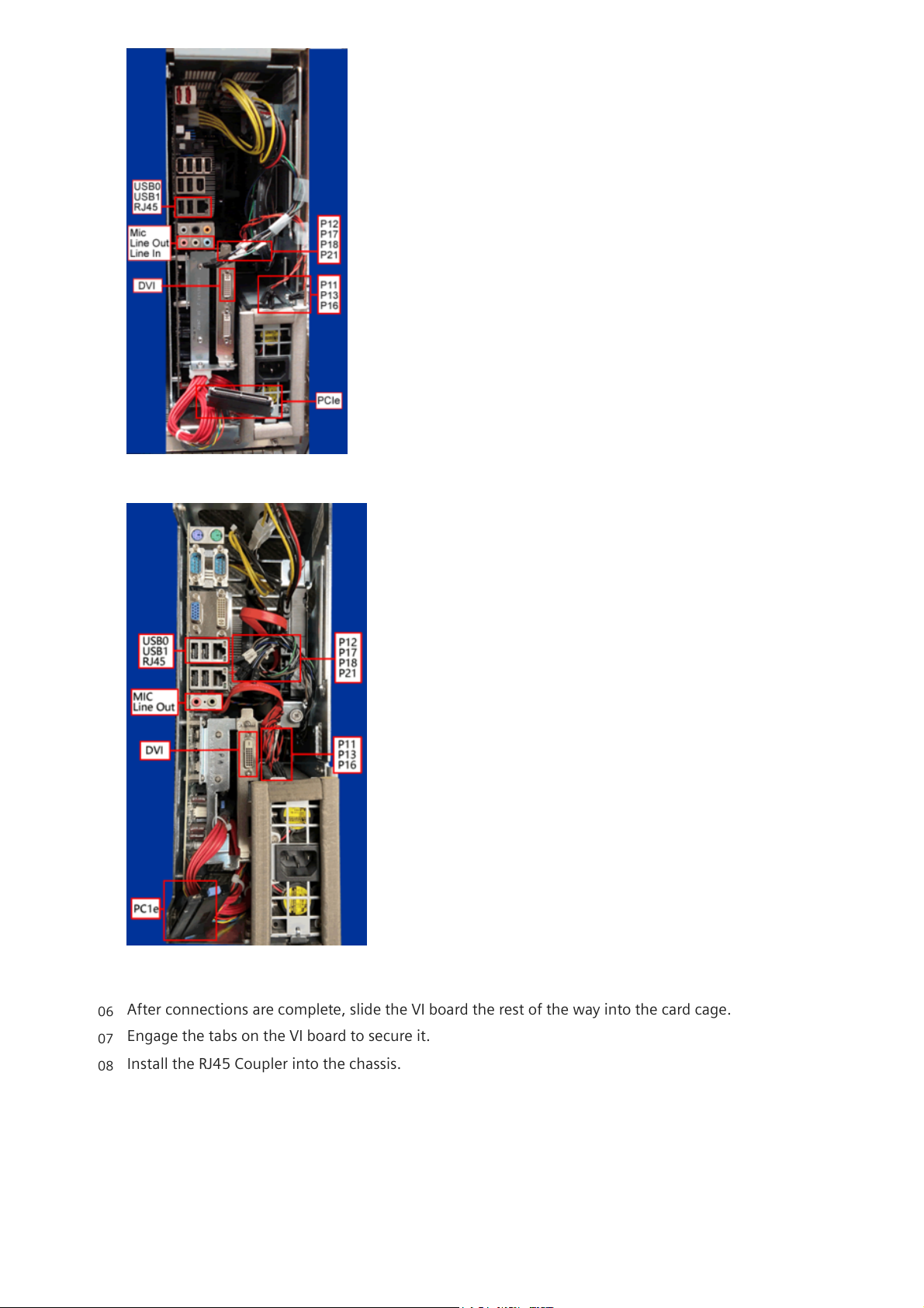
Fig.198:RM300 Cables and Connections
Fig.199: RM301 Cables and Connections
After connections are complete, slide the VI board the rest of the way into the card cage.
06
Engage the tabs on the VI board to secure it.
07
Install the RJ45 Coupler into the chassis.
08
21.08.24, 11:47
ACUSON S3000
localhost:3006/#/documents/US22-101.841.01.XX.02.json?fragment=%2FUS22-101.841.01.XX.02.d3ff9f51462ebbea0a53dbda7dfa389b.html&…
18/33
Page 19

Fig.200:RJ45 Coupler
Connect the Ethernet Cable(s) and Isolator (if applicable):
i
On the RM301, there are two (2) identical USB and RJ45 connector blocks. Only use
the top connector block.
Fig.201:RM Module USB, RJ45 Network Jack, and Audio Cable Connections
Fig.202:Isolator Markings - Network Connection and RM300 Connection
i
The RM300 requires two (2) Ethernet Cables with the Isolator. The RM200 and
RM301 only uses one (1) Ethernet Cable and does not require an Isolator.
09
For the RM200 and RM301: Connect the Ethernet cable between the RM Module RJ45 Network Jack
and the RJ45 Coupler.
For the RM300: Connect two Ethernet cables with an Isolator between the RM Module RJ45
Ensure that the Isolator is installed in the correct direction.
21.08.24, 11:47
ACUSON S3000
localhost:3006/#/documents/US22-101.841.01.XX.02.json?fragment=%2FUS22-101.841.01.XX.02.d3ff9f51462ebbea0a53dbda7dfa389b.html&…
19/33
Page 20
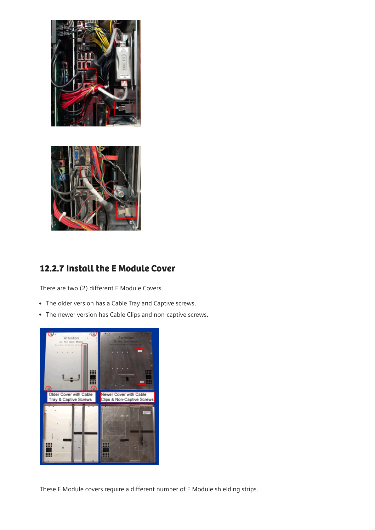
12.2.7Install the E Module Cover
There are two (2) different E Module Covers.
Fig.205:E Module Cover Versions
These E Module covers require a different number of E Module shielding strips.
Fig.203:RM300 Ethernet Cable with Isolator Properly Connected
Fig.204:RM301 Ethernet Cable without Isolator
The older version has a Cable Tray and Captive screws.
The newer version has Cable Clips and non-captive screws.
21.08.24, 11:47
ACUSON S3000
localhost:3006/#/documents/US22-101.841.01.XX.02.json?fragment=%2FUS22-101.841.01.XX.02.d3ff9f51462ebbea0a53dbda7dfa389b.html&…
20/33
Page 21
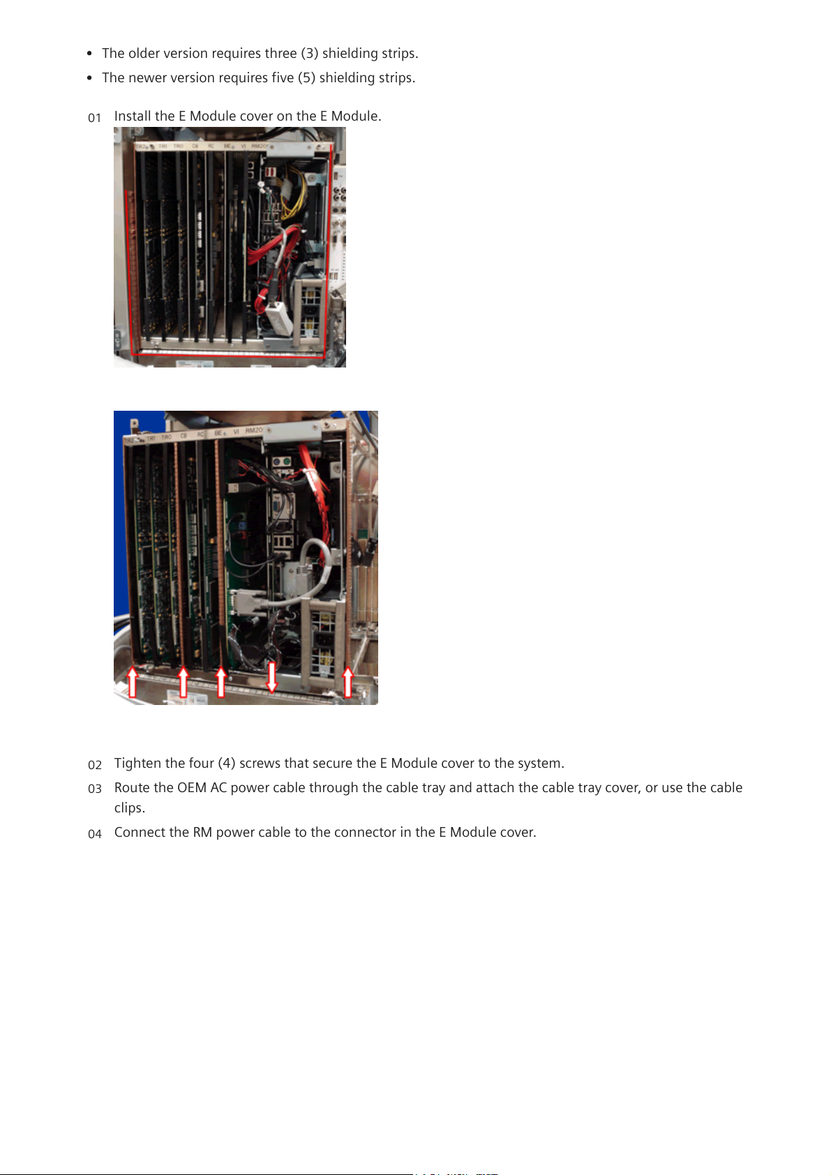
The older version requires three (3) shielding strips.
The newer version requires five (5) shielding strips.
Install the E Module cover on the E Module.
Fig.206:Older E Module with Three (3) Shielding Strips
Fig.207:Newer E Module with Five (5) Shielding Strips
01
Tighten the four (4) screws that secure the E Module cover to the system.
02
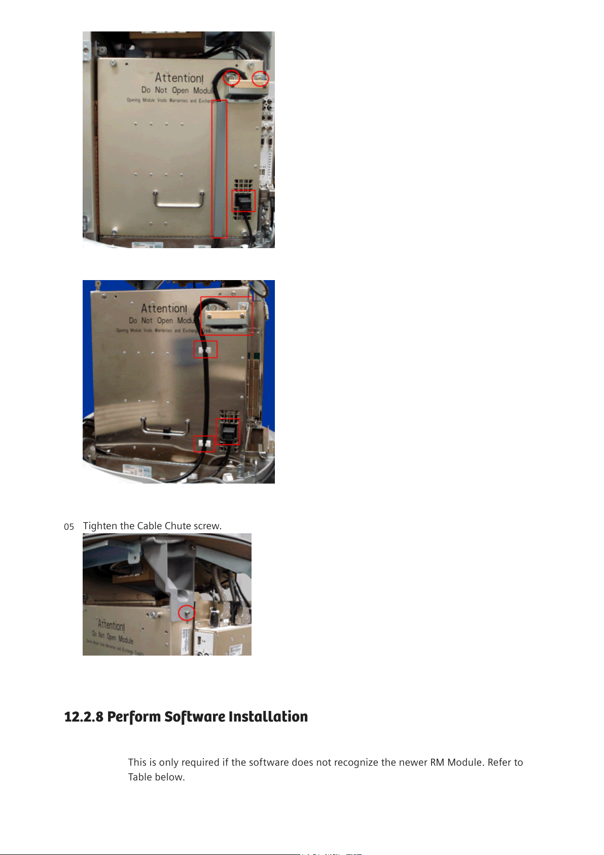
Route the OEM AC power cable through the cable tray and attach the cable tray cover, or use the cable
clips.
03
Connect the RM power cable to the connector in the E Module cover.
04
21.08.24, 11:47
ACUSON S3000
localhost:3006/#/documents/US22-101.841.01.XX.02.json?fragment=%2FUS22-101.841.01.XX.02.d3ff9f51462ebbea0a53dbda7dfa389b.html&…
21/33
Page 22
12.2.8Perform Software Installation
i
This is only required if the software does not recognize the newer RM Module. Refer to
Table below.
Fig.208:Older E Module Cover -- OEM AC Cable Connector and RM Power Cable
Fig.209:Newer E Module Cover -- OEM AC Cable Connector and RM Power Cable
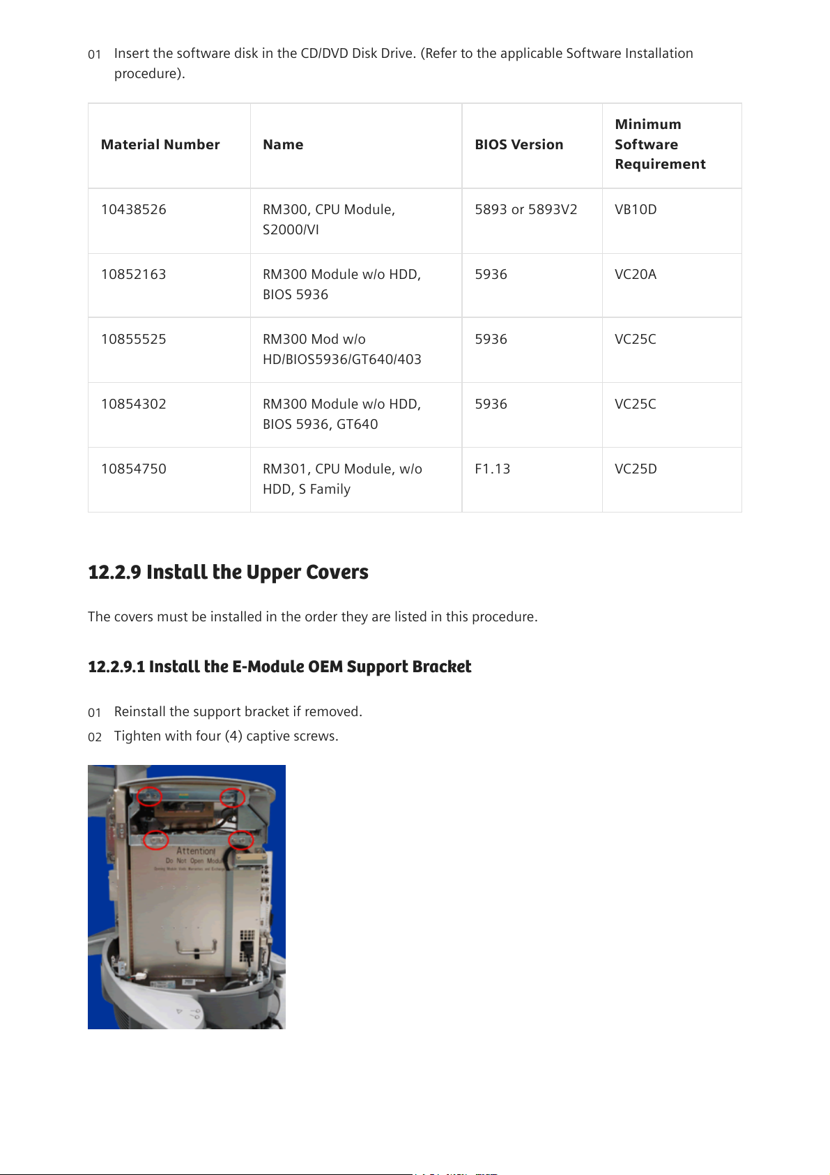
Tighten the Cable Chute screw.
Fig.210:Cable Chute Screw
05
21.08.24, 11:47
ACUSON S3000
localhost:3006/#/documents/US22-101.841.01.XX.02.json?fragment=%2FUS22-101.841.01.XX.02.d3ff9f51462ebbea0a53dbda7dfa389b.html&…
22/33
Page 23
Material Number Name BIOS Version
Minimum
Software
Requirement
10438526 RM300, CPU Module,
S2000/VI
5893 or 5893V2 VB10D
10852163 RM300 Module w/o HDD,
BIOS 5936
5936 VC20A
10855525 RM300 Mod w/o
HD/BIOS5936/GT640/403
5936 VC25C
10854302 RM300 Module w/o HDD,
BIOS 5936, GT640
5936 VC25C
10854750 RM301, CPU Module, w/o
HDD, S Family
F1.13 VC25D
Tab.11:RM300 Module Hardware/Software Matrix
12.2.9Install the Upper Covers
The covers must be installed in the order they are listed in this procedure.
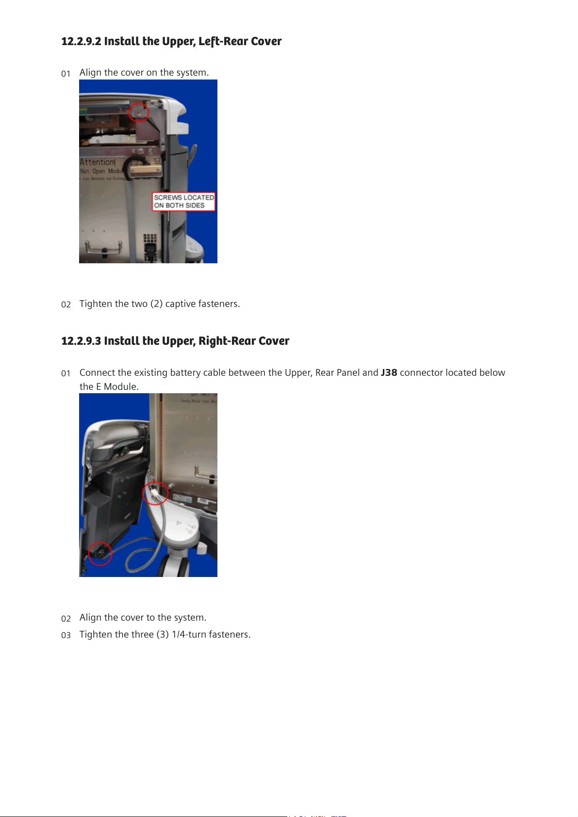
12.2.9.1Install the E-Module OEM Support Bracket
Fig.211:E-Module OEM Support Bracket
Insert the software disk in the CD/DVD Disk Drive. (Refer to the applicable Software Installation
procedure).
01
Reinstall the support bracket if removed.
01
Tighten with four (4) captive screws.
02
21.08.24, 11:47
ACUSON S3000
localhost:3006/#/documents/US22-101.841.01.XX.02.json?fragment=%2FUS22-101.841.01.XX.02.d3ff9f51462ebbea0a53dbda7dfa389b.html&…
23/33
Page 24
12.2.9.2Install the Upper, Left-Rear Cover
12.2.9.3Install the Upper, Right-Rear Cover
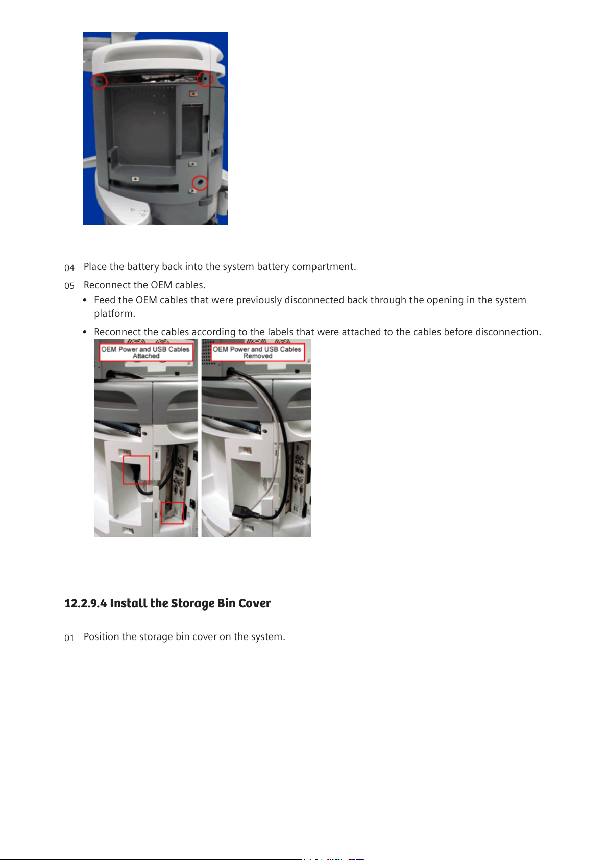
Align the cover on the system.
Fig.212:Upper Left Rear Cover - Screw Shown
01
Tighten the two (2) captive fasteners.
02
Connect the existing battery cable between the Upper, Rear Panel and J38 connector located below
the E Module.
Fig.213:Battery Cable
01
Align the cover to the system.
02
Tighten the three (3) 1/4-turn fasteners.
03
21.08.24, 11:47
ACUSON S3000
localhost:3006/#/documents/US22-101.841.01.XX.02.json?fragment=%2FUS22-101.841.01.XX.02.d3ff9f51462ebbea0a53dbda7dfa389b.html&…
24/33
Page 25
12.2.9.4Install the Storage Bin Cover
Fig.214:Upper Right Rear Cover Shown
Place the battery back into the system battery compartment.
04
Reconnect the OEM cables.
05
Feed the OEM cables that were previously disconnected back through the opening in the system
platform.
Reconnect the cables according to the labels that were attached to the cables before disconnection.
Fig.215:OEM Cables
Position the storage bin cover on the system.
01
21.08.24, 11:47
ACUSON S3000
localhost:3006/#/documents/US22-101.841.01.XX.02.json?fragment=%2FUS22-101.841.01.XX.02.d3ff9f51462ebbea0a53dbda7dfa389b.html&…
25/33
Page 26
12.2.9.5Install the Upper, Right-Front Cover
12.2.9.6Install the Physio Cover
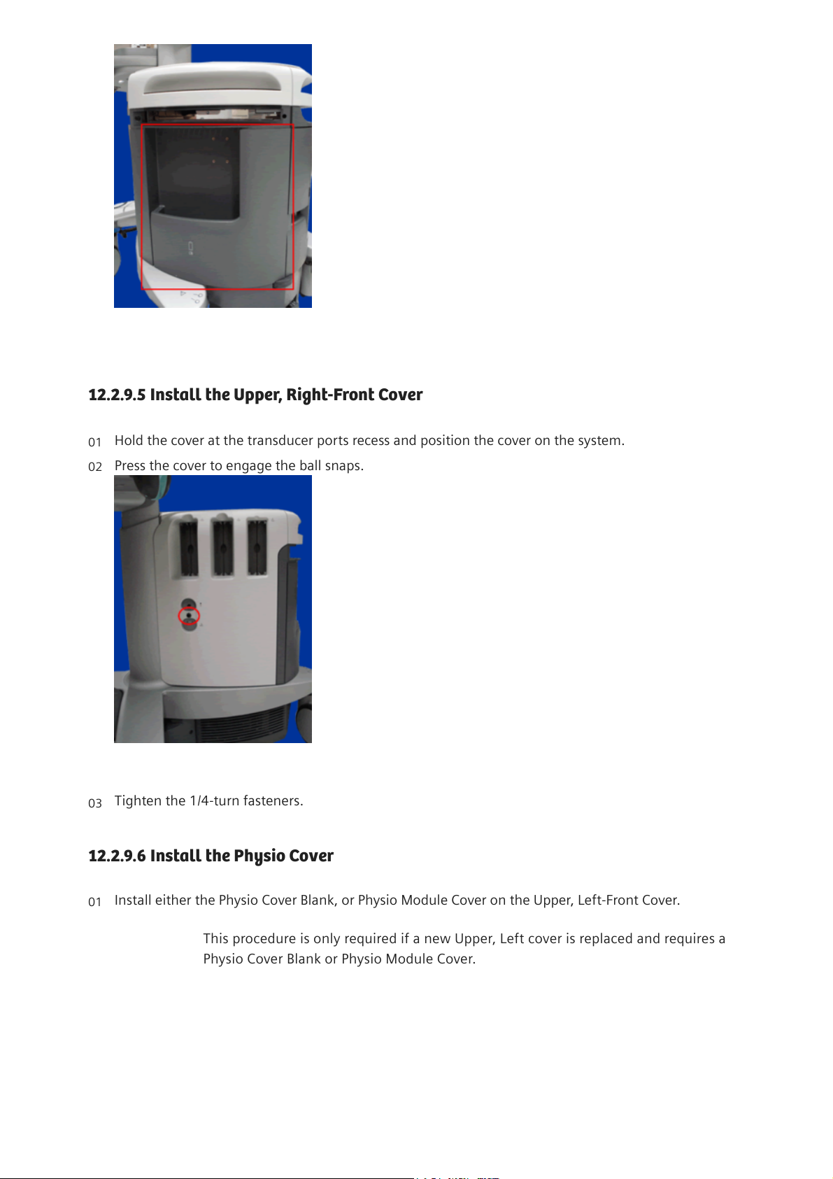
Fig.216:Storage Bin Cover
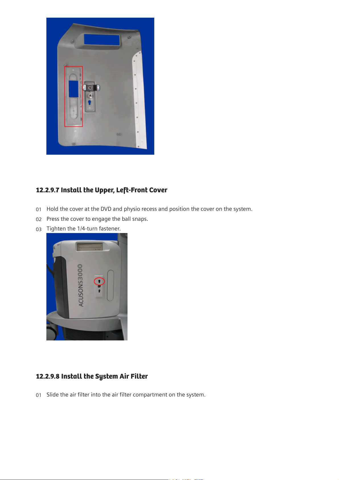
Hold the cover at the transducer ports recess and position the cover on the system.
01
Press the cover to engage the ball snaps.
Fig.217:Upper Right Front Cover
02
Tighten the 1/4-turn fasteners.
03
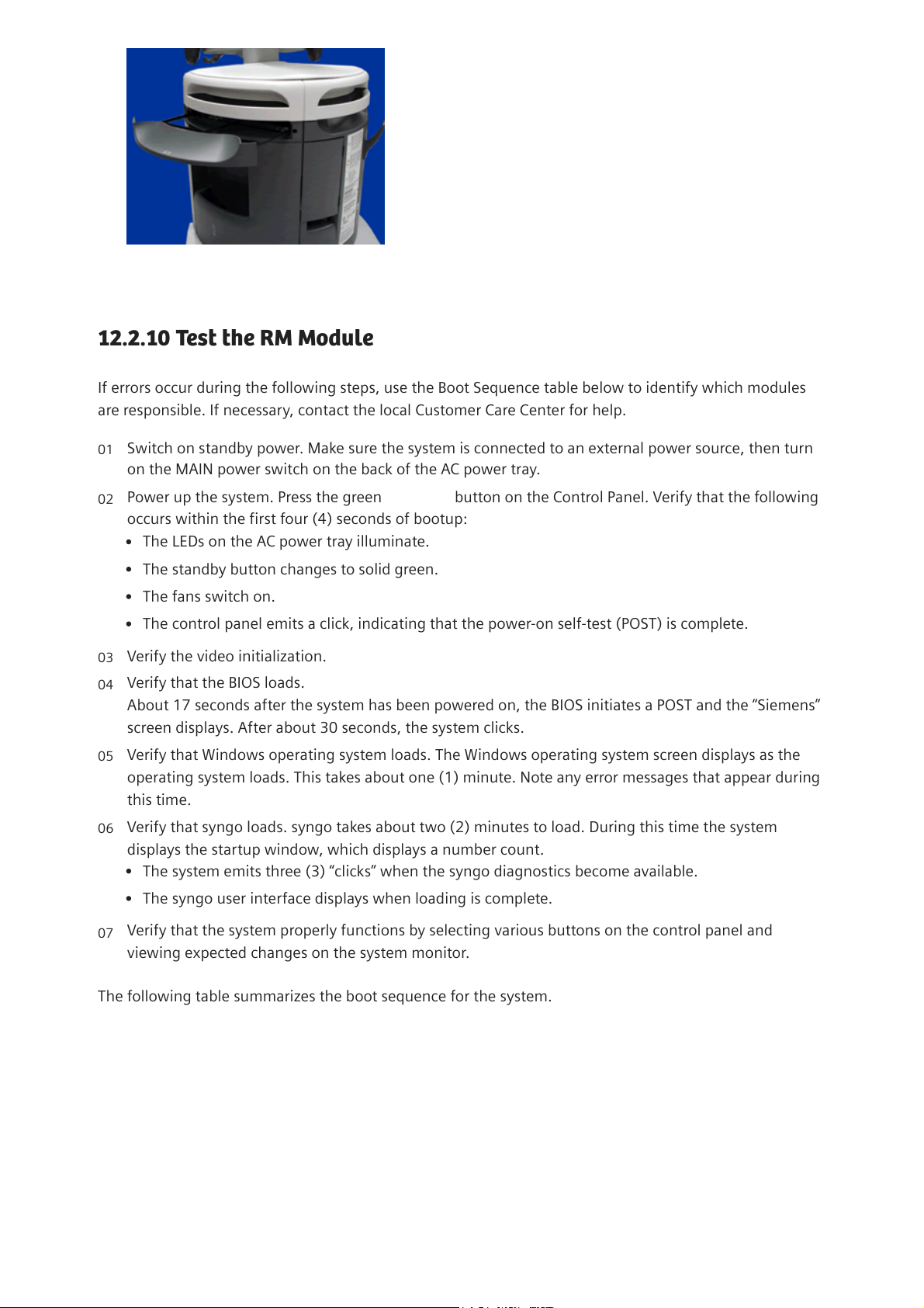
Install either the Physio Cover Blank, or Physio Module Cover on the Upper, Left-Front Cover.
i
This procedure is only required if a new Upper, Left cover is replaced and requires a
Physio Cover Blank or Physio Module Cover.
01
21.08.24, 11:47
ACUSON S3000
localhost:3006/#/documents/US22-101.841.01.XX.02.json?fragment=%2FUS22-101.841.01.XX.02.d3ff9f51462ebbea0a53dbda7dfa389b.html&…
26/33
Page 27
12.2.9.7Install the Upper, Left-Front Cover
12.2.9.8Install the System Air Filter
Fig.218: Upper, Left Cover - Physio Cover Location
Hold the cover at the DVD and physio recess and position the cover on the system.
01
Press the cover to engage the ball snaps.
02
Tighten the 1/4-turn fastener.
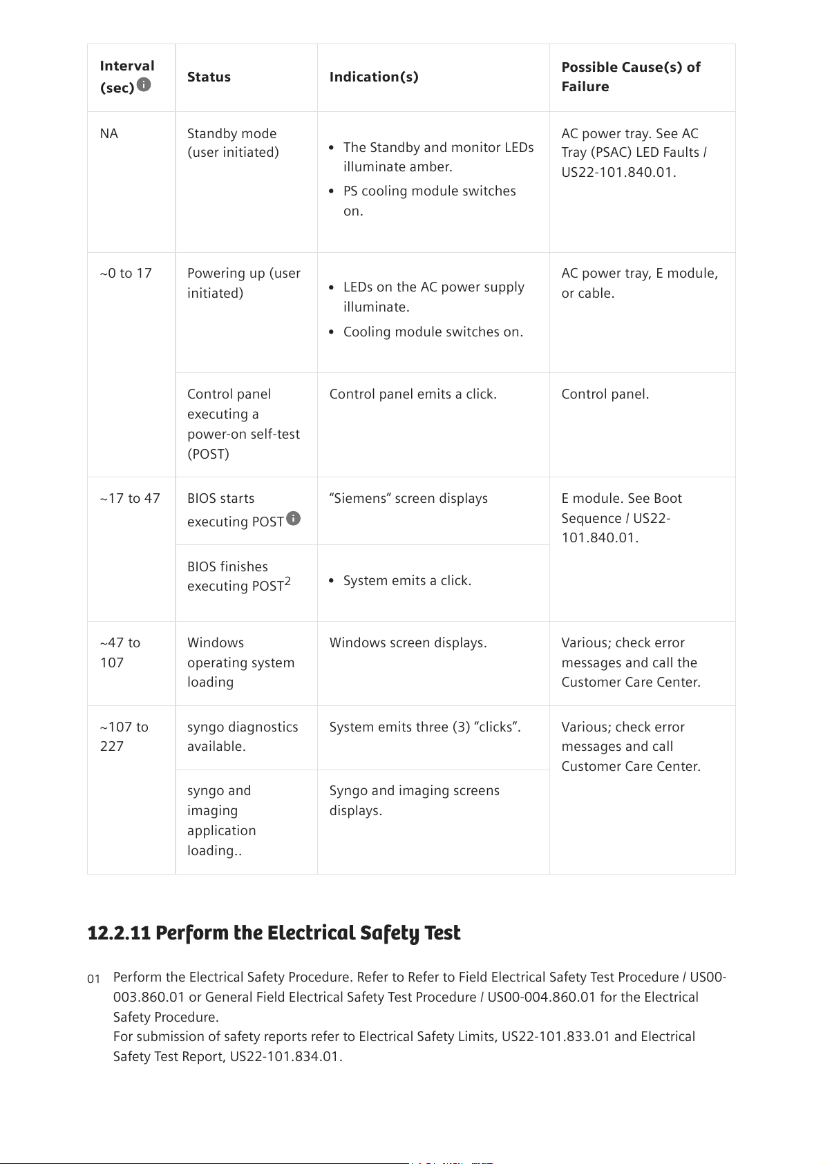
Fig.219:Left Front Cover Shown
03
Slide the air filter into the air filter compartment on the system.
01
21.08.24, 11:47
ACUSON S3000
localhost:3006/#/documents/US22-101.841.01.XX.02.json?fragment=%2FUS22-101.841.01.XX.02.d3ff9f51462ebbea0a53dbda7dfa389b.html&…
27/33
Page 28
12.2.10Test the RM Module
If errors occur during the following steps, use the Boot Sequence table below to identify which modules
are responsible. If necessary, contact the local Customer Care Center for help.
The following table summarizes the boot sequence for the system.
Fig.220:Air Filter Shown
Switch on standby power. Make sure the system is connected to an external power source, then turn
on the MAIN power switch on the back of the AC power tray.
01
Power up the system. Press the green STANDBY button on the Control Panel. Verify that the following
occurs within the first four (4) seconds of bootup:
02
The LEDs on the AC power tray illuminate.
The standby button changes to solid green.
The fans switch on.
The control panel emits a click, indicating that the power-on self-test (POST) is complete.
Verify the video initialization.
03
Verify that the BIOS loads.
About 17 seconds after the system has been powered on, the BIOS initiates a POST and the “Siemens”
screen displays. After about 30 seconds, the system clicks.
04
Verify that Windows operating system loads. The Windows operating system screen displays as the
operating system loads. This takes about one (1) minute. Note any error messages that appear during
this time.
05
Verify that syngo loads. syngo takes about two (2) minutes to load. During this time the system
displays the startup window, which displays a number count.
06
The system emits three (3) “clicks” when the syngo diagnostics become available.
The syngo user interface displays when loading is complete.
Verify that the system properly functions by selecting various buttons on the control panel and
viewing expected changes on the system monitor.
07
21.08.24, 11:47
ACUSON S3000
localhost:3006/#/documents/US22-101.841.01.XX.02.json?fragment=%2FUS22-101.841.01.XX.02.d3ff9f51462ebbea0a53dbda7dfa389b.html&…
28/33
Page 29
Interval
(sec)
Status Indication(s)
Possible Cause(s) of
Failure
NA Standby mode
(user initiated)
AC power tray. See AC
Tray (PSAC) LED Faults /
US22-101.840.01.
~0 to 17 Powering up (user
initiated)
AC power tray, E module,
or cable.
Control panel
executing a
power-on self-test
(POST)
Control panel emits a click. Control panel.
~17 to 47 BIOS starts
executing POST
“Siemens” screen displays E module. See Boot
Sequence / US22-
101.840.01.
BIOS finishes
executing POST
~47 to
107
Windows
operating system
loading
Windows screen displays. Various; check error
messages and call the
Customer Care Center.
~107 to
227
syngo diagnostics
available.
System emits three (3) “clicks”. Various; check error
messages and call
Customer Care Center.
syngo and
imaging
application
loading..
Syngo and imaging screens
displays.
Tab.12:Boot Sequence Summary
12.2.11Perform the Electrical Safety Test
The Standby and monitor LEDs
illuminate amber.
PS cooling module switches
on.
LEDs on the AC power supply
illuminate.
Cooling module switches on.
2 System emits a click.
Perform the Electrical Safety Procedure. Refer to Refer to Field Electrical Safety Test Procedure / US00-
003.860.01 or General Field Electrical Safety Test Procedure / US00-004.860.01 for the Electrical
Safety Procedure.
For submission of safety reports refer to Electrical Safety Limits, US22-101.833.01 and Electrical
Safety Test Report, US22-101.834.01.
01
21.08.24, 11:47
ACUSON S3000
localhost:3006/#/documents/US22-101.841.01.XX.02.json?fragment=%2FUS22-101.841.01.XX.02.d3ff9f51462ebbea0a53dbda7dfa389b.html&…
29/33
Page 30
Siemens Healthineers © 2024|v3.5.1
| Disclaimer and Copyright | Corporate Information | Privacy Policy
| Cookie Policy | Terms of Use
21.08.24, 11:47
ACUSON S3000
localhost:3006/#/documents/US22-101.841.01.XX.02.json?fragment=%2FUS22-101.841.01.XX.02.d3ff9f51462ebbea0a53dbda7dfa389b.html&…
30/33
Page 31

21.08.24, 11:47
ACUSON S3000
localhost:3006/#/documents/US22-101.841.01.XX.02.json?fragment=%2FUS22-101.841.01.XX.02.d3ff9f51462ebbea0a53dbda7dfa389b.html&…
31/33
Page 32

21.08.24, 11:47
ACUSON S3000
localhost:3006/#/documents/US22-101.841.01.XX.02.json?fragment=%2FUS22-101.841.01.XX.02.d3ff9f51462ebbea0a53dbda7dfa389b.html&…
32/33
Page 33

21.08.24, 11:47
ACUSON S3000
localhost:3006/#/documents/US22-101.841.01.XX.02.json?fragment=%2FUS22-101.841.01.XX.02.d3ff9f51462ebbea0a53dbda7dfa389b.html&…
33/33
 Loading...