

Page 1
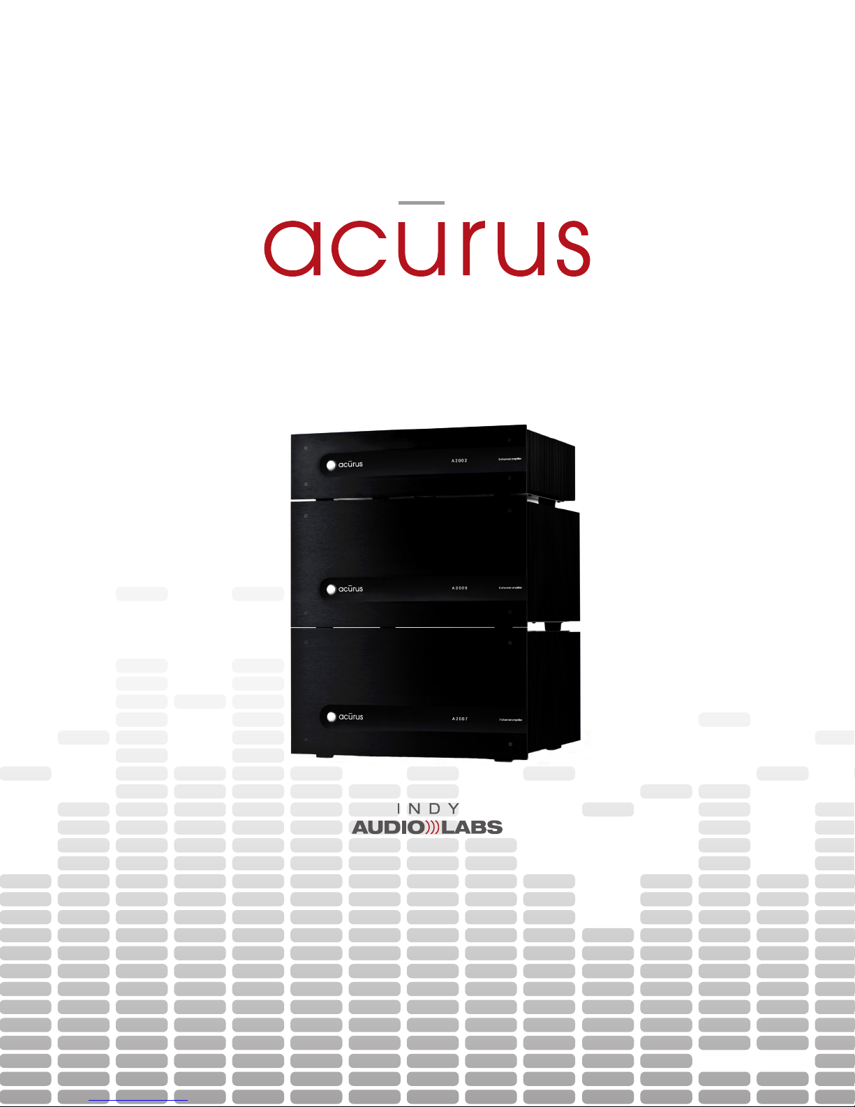
A2000-Series Amplier User Guide
2, 5 and 7-channel models
Document No. 1000571
Page 2
IMPORTANT SAFETY INSTRUCTIONS
CAUTION:
RISK OF ELECTRIC SHOCK!
DO NOT OPEN!
CAUTION! To reduce the risk of electric shock and fire, do not remove the cover or back plate of the device
enclosure. There are no user serviceable parts inside. Refer servicing to an Acurus authorized service center.
CAUTION! The international symbol of a lightning bolt inside a triangle is intended to alert the user to
uninsulated “dangerous voltage” within the device enclosure. The international symbol of an exclamation
point inside a triangle is intended to alert the user to the presence of important operating, maintenance and
servicing information in the manual accompanying the device.
WARNING! To reduce the risk of fire or electrical shock, do not expose this equipment to rain or moisture.
1. Read Instructions – All safety and operating instructions should be
read before operating the device.
2. Retain Instructions – The safety and operating instructions should be
retained for future reference.
3. Heed Warnings – All warnings on the device and in the operating
instructions should be adhered to.
4. Follow instructions – All operating and safety instructions should
be followed.
5. Attachments – Do not use attachments not recommended by the
product manufacturer as they may cause hazards.
6. Water and Moisture – Do not use this product near water (for
example, near a bath tub, wash bowl, kitchen sink, or laundry tub;
in a wet basement; or near a swimming pool; and the like).
7. Ventilation – Slots and openings in the cabinet are provided for
ventilation and to ensure reliable operation of the product and to
protect it from overheating, and these openings must not be blocked
or covered. The openings should never be blocked by placing the
product on a bed, sofa, rug, or other similar surface. This product
should not be placed in a built-in installation such as a bookcase
or rack unless proper ventilation is provided or the manufacturer’s
instructions have been adhered to.
8. Heat – This product should be situated away from heat sources
such as radiators, heat registers, stoves, or other products that
produce heat.
9. Power Sources – This product should be operated only from the
type of power source indicated on the marking label. If you are not
sure of the type of power supply in your home, consult with your
product dealer or the local power company. For products intended
to operate from battery power, or other sources, refer to the
operating instructions.
10. Grounding – This product is equipped with a three-wire groundingtype plug, a plug having a third (grounding) pin. This plug will only
fit into a grounding-type power outlet. This is a safety feature. If you
are unable to insert the plug into the outlet, contact your electrician
to replace your obsolete outlet. Do not defeat the safety purpose of
the grounding-type plug.
11. Power Cord Protection – Power supply cords should be routed
so that they are not likely to be walked on or pinched by items
placed upon or against them, paying particular attention to cords
at plugs, convenience receptacles, and the point where they exit
from the product.
12. Overloading – Do not overload wall outlets, extension cords, or
integral convenience receptacles as this can result in a risk of fire
or electrical shock.
13. Lightning and Periods of Non-Use – For added protection for this
product during a lightning storm, or when it is left unattended and
unused for long periods of time, unplug it from the wall outlet and
disconnect the antenna or cable system. This will prevent damage
to the product due to lightning and powerline surges.
14. Cleaning – Unplug this product from the wall outlet before cleaning.
Do not use liquid cleaners or aerosol cleaners. Use a damp cloth
for cleaning.
15. Object and Liquid Entry – Never push objects of any kind into this
product through openings as they may touch dangerous voltage
points or short-out parts that could result in a fire or electric shock.
Never spill liquid of any kind on the product.
16. Damage Requiring Service – Unplug this product from the wall
outlet and refer servicing to qualified service personnel under the
following conditions:
a) When the power supply cord or plug is damaged,
b) If liquid has been spilled, or objects have fallen into the product,
c) If the product has been exposed to rain or water,
d) If the product does not operate normally by following the
operating instructions. Adjust only those controls that are covered
by the operating instructions as an improper adjustment of other
controls may result in damage and often will require extensive
work by a qualified technician to restore the product to its
normal operation,
e) If the product has been dropped or damaged in any way, or
f) When the product exhibits a distinct change in performance – this
indicates a need for service.
17. Replacement Parts – When replacement parts are required, be sure
the service technician has used replacement parts specified by the
manufacturer or that have the same characteristics as the original
parts. Unauthorized substitutions may result in fire, electric shock,
or other hazards.
18. Safety Check – Upon completion of any service or repairs to this
product, ask the service technician to perform safety checks to
determine that the product is in proper operating condition.
19. Servicing – Do not attempt to service this product yourself as
opening or removing covers may expose you to dangerous voltage
or other hazards. Refer all servicing to qualified service personnel.
If this unit is purchased outside of the U.S., please contact your
local dealer or distributor for service center information. If purchased
inside the U.S. and dealer service is not available, contact Acurus
Customer Service for a return authorization (RA) number before
shipping. For further service information, contact:
ACURUS CUSTOMER SERVICE
phone: 1-866-781-7284
email: [email protected]
5225 EXPLORATION DRIVE
INDIANAPOLIS, IN 46241
A 2 0 0 0 - S E R I E S A M P L I F I E R U S E R G U I D E
2
©2012 Indy Audio Labs, LLC all rights reserved / Revision20120420
Document No. 1000571
Page 3

contents
2
Important Safety Instructions
5
Becoming Familiar with Your
New Acurus Amplifier
Front Panel
Exterior Surfaces
Rear and Bottom Panel
3
Contents
7
Placement and Setup
Shelf Mounting
Rack Mounting
4
Congratulations
Unpacking
Outer and Inner Carton
Package Contents
Retain your Packaging
Register your Product
Record your Unit Information
8
System Planning and Optimizing
Making System Connections
Speaker Outputs
Audio Inputs
Pre-amp On/Off Control
Mains (AC) Power
Control Networks
9
Operation
Standby Mode
Normal Operation
Acurus’ Proprietary Enhanced
Ethernet Control (E2C)
Amplier Control and
Status using E2C
18
Design Notes
©2012 Indy Audio Labs, LLC all rights reserved / Revision20120420
Document No. 1000571
14
Problem Resolution
Troubleshooting Table
Obtaining Additional Help
19
Warranty
U.S. and Canada
Applicable Territories
16
Technical Specifications
A2002 Architects and
Engineering Specications
A2005 Architects and
Engineering Specications
A2007 Architects and
Engineering Specications
20
About Acurus and
Indy Audio Labs
A 2 0 0 0 - S E R I E S A M P L I F I E R U S E R G U I D E
3
Page 4

congratulations
Congratulations on your purchase of an Acurus A2000-
series 2, 5 or 7-channel amplier. Each Acurus A2000
series amplier is a state-of-the-art component featuring
high-end audio performance combined with unprec-
edented control and connectivity. Years of dedicated
research, extensive testing, and engineering renement
went into the creation of this product. Since 1993, Acu-
rus has been delivering high-value, high-performance
electronics. Just like the rst Acurus amps to roll off the
assembly line nearly 20 years ago, your Acurus was
designed, hand-assembled and tested with pride by
engineers, technicians and skilled assemblers in the
United States of America. You should expect years of
trouble-free operation from your product investment.
Package Contents
Inside the box you should nd the following:
1. Acurus amplifier
1. Foam Bumpers (2)
1. Power Cord
1. User Guide
1. Warranty Card
In the unlikely event of any of the above items
missing, immediately contact your dealer or
Acurus Customer Service:
ACURUS CUSTOMER SERVICE
phone: 1-866-781-7284
email: [email protected]
5225 EXPLORATION DRIVE
INDIANAPOLIS, IN 46241
Acurus components offer unparalleled performance and
control exibility for the most discriminating listener. Your
A2000-series amplier incorporates many advanced
design and construction features combined
in a superbly crafted amplier.
unpacking
Outer and Inner Carton
Using a sharp object such as a knife or scissors, care-
fully open the outer single-walled (brown) shipping car-
ton and inner double-walled (white) packaging cartons
along their top seams.
Your Acurus amplier is wrapped in a protective poly
bag and sandwiched between 100% recycled foam
bumpers. Carefully lift the amplier out of the package
with the foam bumpers attached.
TEAM LIFT! - To Avoid injury, lift with
someone else - your amplifier is very heavy!
Retain your Packaging
We highly recommend retaining your box and packag-
ing materials as these are the best way to protect your
amplier in transit. Should warranty service be required,
you MUST either use your original packaging materials
or request new packaging from Acurus Customer Serv-
ice (for a nominal fee).
Register your Product
In order to validate your purchase and qualify for the full
ve (5) year parts and labor manufacturer’s warranty on
your new Acurus product, you must have purchased it
from an authorized Acurus retailer AND you must return
the included warranty card completely lled out within
30 days of purchase.
Record your Unit Information
For future reference, we recommend recording your
product information here:
Model No.
Serial No.
Date of Purchase
Date Registration Sent
A 2 0 0 0 - S E R I E S A M P L I F I E R U S E R G U I D E
4
©2012 Indy Audio Labs, LLC all rights reserved / Revision20120420
Document No. 1000571
Page 5
becoming familiar
with your new
acurus amplifier
indication meaning
unlit
steady red
flashing red
blue
No power input
Low-power (idle) mode
Amplifier circuits initializing
Amplifier ON
Your Acurus amplier has been engineered to provide
years of trouble-free enjoyment when installed and used
according to this guide. This section will help you get fa-
miliarized with all the physical features of this component.
Front Panel
The front-panel design of your new Acurus was execut-
ed with beauty, simplicity and control condence as
the primary goals.
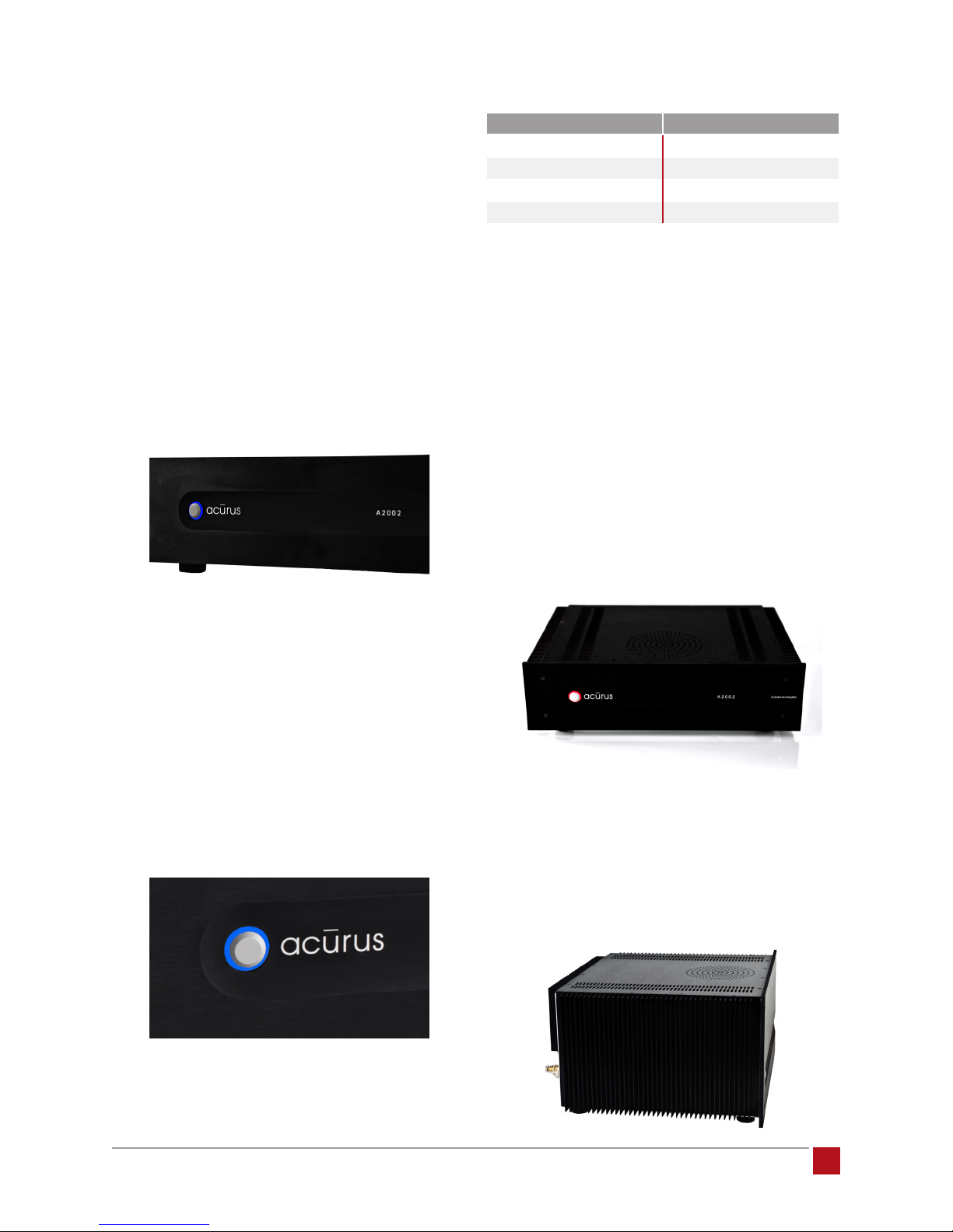
Power Button: To turn on your amplier, simply press the
power button. This custom-designed solid aluminum
push-button responds with positive feedback. For auto-
matic turn-on via an external pre-amp or pre-amp/proc-
essor, see section entitiled Pre-amp On/Off Control, p9.
After pushing the power button, the light ring remains
red briey as the amplier circuits are initialized.
Once ready for audio, the light ring illuminates blue.
To adjust the brightness of the light ring indicator for
your particular environment via Acurus Enhanced Ether-
net Control (E2C), see section entitled Acurus’ Propri-
etary Enhanced Ethernet Control (E2C), p10.
Exterior Surfaces
The top and sides of your Acurus amplier are designed
for both style and function.
Top Cover: The brushed aluminum top cover contains
ventillation slots to allow convective air ow through the
internal chassis, drawing air from underneath to keep
the internal circuit cards and transformer running cooler.
Status Light: Our proprietary status light design consists
of a light ring surrounding the power button. This status
light is clearly visible at a wide range of angles and in
varying lighting conditions. It indicates amplier status
as shown below:
©2012 Indy Audio Labs, LLC all rights reserved / Revision20120420
Document No. 1000571
Sides: The extruded aluminum sides include heat trans-
fer ns to direct heat away from the internal amplier
circuits to the ambient air. Unlike many other amplier
designs, Acurus A2000-series amplier ns are mounted
externally to achieve the most effective convective
cooling action for all channels in both cabinet-mount
and rack-mount installations.
A 2 0 0 0 - S E R I E S A M P L I F I E R U S E R G U I D E
5
Page 6
Rear and Bottom Panel
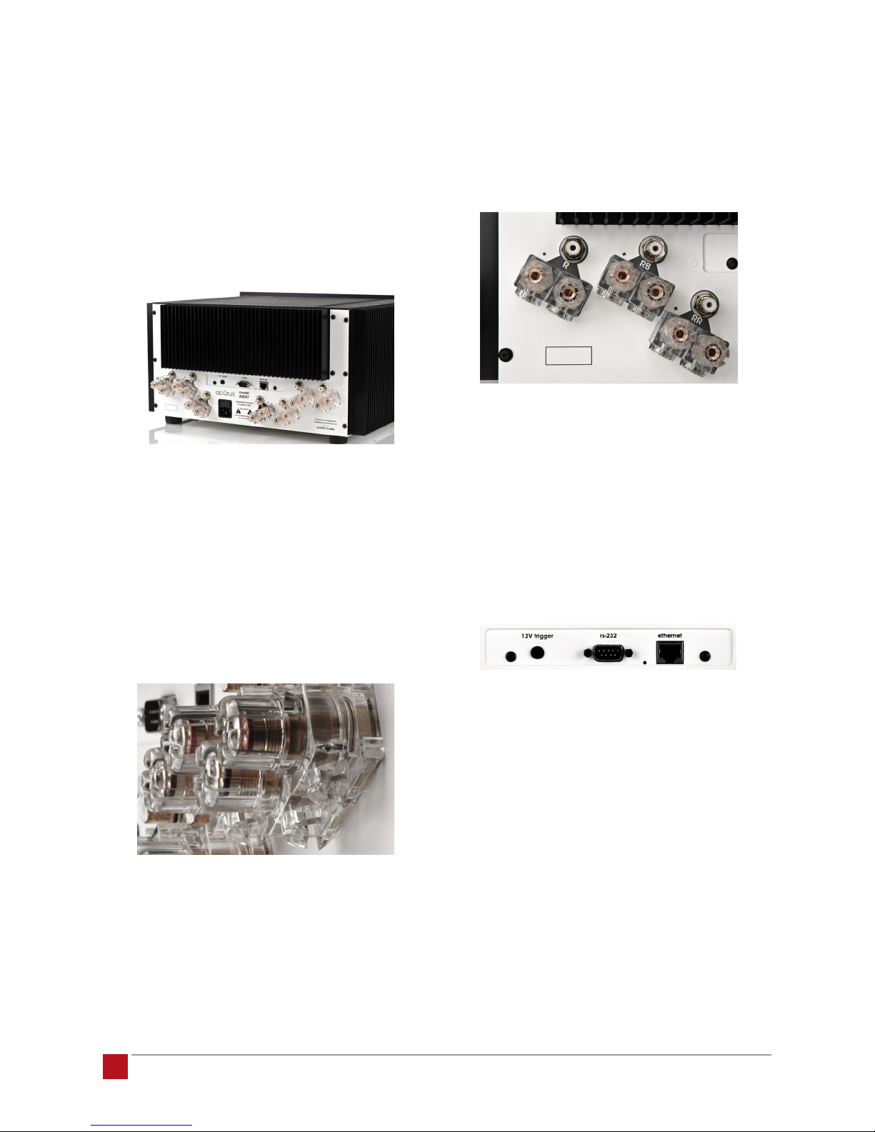
The rear panel of your Acurus amplier has been pains-
takingly designed for ease of installation.
Rear panel nish: The rear chassis features a durable
powdercoat nish to provide both scratch resistance
and high-contrast colors for installation in dimly-lit
environments. All labels are clear and concise utilizing
easy-to-read fonts.
Speaker Outputs: Speaker outputs are discrete, rug-
ged, 60-amp gold-plated binding posts with anti-touch
protective clear housings.
All posts are color-coded with red and black rings for
+ and - speaker polarity and are spaced in pairs to ac-
commodate dual banana jacks. All pairs are angled to
minimize tangling and strain on heavy gauge speaker
wire exits, particularly in rack installations.
Audio Inputs: Each audio input consists of a high-
conductivity, gold-plated, isolated RCA jack logically ar-
ranged near its corresponding output connection. Rear
panel graphics clearly indicate which inputs correspond
to which outputs.
AC Mains Inlet: The AC mains inlet is a removeable IEC-
320-style high-current appliance inlet with integral mains
fuse holder. This inlet is approved for international use.
Network Module: Your new Acurus ampler includes
built-in remote control and networking capabilities that
provide a wide array of options and ultimate installation
exibility. All these functions are provided in an upgrade-
able hardware card.
1 2 3 4
A 2 0 0 0 - S E R I E S A M P L I F I E R U S E R G U I D E
6
1 - External 12V Trigger Input Within the network
module section, a 3.5mm jack allows for connection to a
typical 5-24V trigger output from an external pre-amp or
pre-amp/processor via a stereo 3.5mm cable.
2 - System Controller (RS-232) Input The network mod-
ule section contains an RS-232 DB-9 connector for inter-
face to an external system controller. Contact Indy Audio
Labs for a list of veried control system manufacturers.
3 - Ethernet Network Active LED The Ethernet Network
Active LED illuminates green with an active network
connection between the Acurus amplier and a network
switch or router.
©2012 Indy Audio Labs, LLC all rights reserved / Revision20120420
Document No. 1000571
Page 7
4 - Ethernet Jack The Ethernet jack enables connection
to either an external system controller or to a standard
home Ethernet 10/100 network switch or router port.
Control and status monitoring of the amplier using any
device with a web browser is supported via the web
server embedded in the Acurus amplier.
It is NEVER advisable to:
1. Enclose the unit in a cabinet without air ow or ad-
equate ventilation, particularly across the heat ns
along the side and back of the unit.
2. Place the unit near a source of moisture such as a
window or a live plant
Feet: Heavy-duty thermoplastic rubber feet ensure good
underside airow, isolate your amplier from external
vibration and protect the surface nish of AV furniture
underneath.
For rack-mount installations where other equipment is in-
stalled directly adjacent, these feet are easily removed.
placement
and setup
An enjoyable home entertainment experience always
begins with carefully planned placement and setup of
system components. This section will provide guidance
on how to best install your new Acurus amplier.
Shelf Mounting
When planning to mount on a shelf, be aware of the
physical dimensions of your Acurus amplier as outlined
in the section entitled Technical Specifications, p16.
3. Place other components in a stack on top of the
amplier
4. Place the amplier on a carpeted surface
5. Remove the safety ground connector from the AC
mains cord
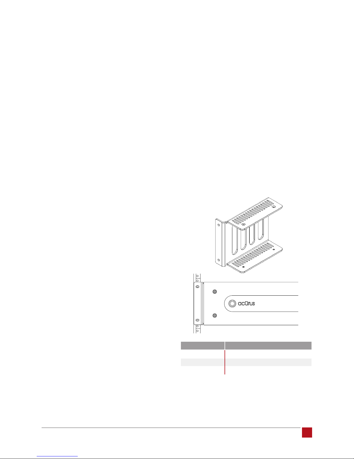
Rack Mounting
Your Acurus amplier can easily be congured to mount
in a standard 19-inch rack cabinet with an optional
Acurus rack mount accessory kit. Hardware and
detailed installation instructions are included.
It is ALWAYS advisable to:
1. Provide ample space above the unit (1-2 inches is
the minimum preferred)
2. Provide plenty of room (at least 1-2 inches) between
the sides of the unit at nearby surfaces or other
components
3. Locate the unit near an AC outlet or power condition-
er and avoid using extension cords or power strips
4. Locate the amplier as close as possible to the pre-
amp or pre-processor
5. Use as short length wire leads as practical, espe-
cially on the amplier inputs
6. Connect the amplier to the same mains circuit as
the pre-amplier
©2012 Indy Audio Labs, LLC all rights reserved / Revision20120420
Document No. 1000571
model acurus rack-mount kit part number
A2002
A2005
A2007
Contact your dealer or Acurus Customer Service with questions or
to request the rack mount kit designed specifically for your amplifier
model.
A 2 0 0 0 - S E R I E S A M P L I F I E R U S E R G U I D E
1000548
1000549
1000549
7
Page 8

system planning
and optimizing
In order to experience the best performance from your
amplier, the entire system needs to be planned and
components carefully selected to work together. Your
authorized Acurus dealer is trained to be able to help
you ensure your components work well together.
The following are some helpful guidelines to ensure your
Acurus amplier is well-matched to the other compo-
nents in your system.
5. Well-designed computer-based audio sources
should have isolated grounds in order to avoid
hum and buzz associated with connecting audio
systems with typical digital system power supplies.
Your Acurus dealer can recommend good quality
components that meet these criteria.
6. Systems with cable TV or sattelite source com-
ponents may need isolation transformers or other
ground isolation devices (such as the Modial
“MAGIC” box) in order to reduce or eliminate hum
due to ground loops.
1. Quality loudspeakers can have a dramatic impact
on overall sound quality in a system for a given
room environment. When planning or upgrad-
ing a system, as a rule of thumb, we recommend
budgeting for loudspeakers at or somewhat above
the price range of your amplier electronics. Your
Acurus dealer will be able to advise you on best
loudspeaker selection for your electronics, your
environment, and, most importantly, your listening
preferences.
2. Using higher-efciency loudspeakers (87dB/W/m or
greater) will reduce the average amount of amplier
power consumed to produce a target listening loud-
ness. This effectively helps reserve greater peak
amplier power when loud transient passages are
reproduced.
3. High-power ampliers (over 100W continuous into
8 ohms) are generally OK to pair with speakers with
slightly lower power ratings, particularly if subwoof-
ers are involved. Higher-power ampliers will tend
not to go into clipping distortion as readily as lower-
powered ampliers or receivers. Clipping is a type
of distortion that is prone to damage loudspeakers.
making system
connections
Your Acurus amplier is designed for simple, reliable
connections in a variety of system congurations.
Following the instructions below will ensure optimal
performance from your amplier.
Speaker Outputs
Use a high-quality speaker cable with sufcient guage
wire for the loudspeaker run lead length. Be sure to
observe consistent speaker polarity connections (plus
(+) and minus (-) speaker leads) from amplier to
loudspeaker. The Acurus A2000 series ampliers are
non-polarity inverting.
Physical connection options supported include bare
wire, single banana post, dual banana post, spade con-
nector and wire lead.
Connect loudspeakers to their corresponding speaker
terminals as follows:
4. Preamps should be chosen with output voltage
swing capability equal to or greater than the ampli-
er sensitivity spec for full rated power output (for
example, 1.42V for full rated output). Similarly, an
ideal preamp choice has a noise spec less than or
equal to that of the power amplier.
A 2 0 0 0 - S E R I E S A M P L I F I E R U S E R G U I D E
8
rear panel label loudspeaker position
L
R
C
LR
RR
LB
RB
Front left
Front right
Center
Rear surround left
Rear surround right
Back surround left
Back surround right
©2012 Indy Audio Labs, LLC all rights reserved / Revision20120420
Document No. 1000571
Page 9
Audio Inputs
We recommend using good quality RCA interconnects
to connect the preamp output to the amplier inputs.
Use the same connection scheme as in the table above.
Pre-amp On/Off Control
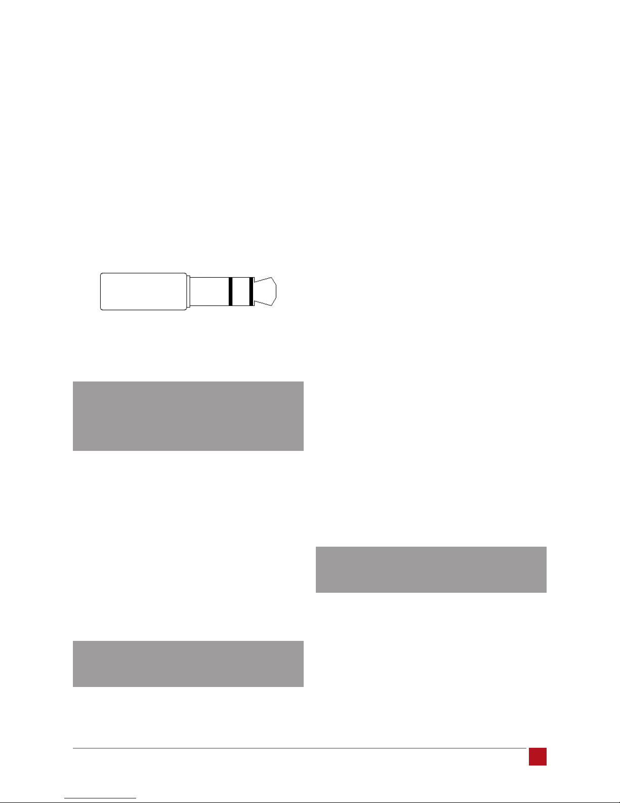
To enable an external 2-channel or surround preamp
to power on your Acurus amplier, connect the trigger
out from the preamp to the the 3.5mm jack labelled 12V
trigger on the Acurus. The jack is wired with its tip active
and will accept a stereo or mono plug.
3.5mm stereo plug
1 2 3
1 – Ground
2 – Ground
3 – Trigger Voltage
Control Networks
Ethernet: In order to take advantage of Acurus En-
hanced Ethernet Control (E2C), connect the Ethernet
port to a 10/100 or faster home network router or switch
port via a standard CAT 5e or newer Ethernet cable. The
network activity indicator near the Ethernet jack illumi-
nates green when network activity is detected.
This port may also be directly connected to a system
controller utilizing Ethernet command protocols. Con-
tact your dealer or Acurus Customer Service in order to
verify compatibility with certain control systems.
RS-232: Connect this port to a system controller using a
9-pin RS-232 serial cable in order to control and monitor
the amplier remotely. Contact your dealer or Acurus
Customer Service in order to verify compatibility with
certain control systems.
operation
NOTE: the front panel power button functions
normally even if the trigger input is used.
The Acurus amplifier will automatically
resume control sync with the external preamp
after the next time system power is cycled.
Mains (AC) Power
Your Acurus A2000 series amplier is equipped with a
high-quality 16 gauge, 3-conductor power cord. Plug
this cord into the back of the amplier and then into
a nearby AC outlet. Avoid using any extension cords
or plugging into other components with rear-panel
switched outlets. If using the amplier with a power con-
ditioner, ensure that the receptacle your amplier plugs
into is capable of providing the full current required by
the amplier. See section entitled Technical Specifica-
tions, p16 for a list of current requirements for each
model amplier in the A2000 series.
It is recommended practice to connect AC
power only after all other connections have
been made.
This section discusses the normal operation of your
Acurus amplier and highlights the control exibility
engineered into this component.
Standby Mode
When rst connected to AC power, your Acurus amplier
initializes in standby mode. This is indicated by a red
illuminated Status Light. Normally, the initialization proc-
ess takes a few seconds. Once the amplier is initial-
ized, it is ready to be powered on.
Before powering on, ensure that your preamp
volume level is not too high or else speaker
damage may occur.
Turn on the amplier by pressing the front panel power
button. If an external trigger input from a preamp is
used, turning on the preamp should automatically turn
on the amplier. The Status Light turns blue indicating
the amplier is active. Toggling the power button again
puts the amplier back into standby mode.
©2012 Indy Audio Labs, LLC all rights reserved / Revision20120420
Document No. 1000571
A 2 0 0 0 - S E R I E S A M P L I F I E R U S E R G U I D E
9
Page 10

LAST ON, FIRST OFF! – To avoid potential
loud pops and/or hum, always turn on the
amplifer last after other components such
as pre-amps and sources and turn off the
amplifer first when powering down.
Normal Operation
Observe these simple guidelines during normal operation:
Setting up Enhanced Ethernet Control (E2C): To enable
E2C, the amplier must be connected directly to a net-
work router or switch as indicated by the green network
activity LED on the rear panel of the amplier. After a
couple minutes connected to the network, the amplier
network module will be initialized and the amplier will
be controllable as a network device.
Source Material: Your Acurus amplier will sound only as
good as the source material it is amplifying. We recom-
mend CD-quality or higher bitrate sources in order to
experience the full capabilities of your new amplier.
You’ll probably nd that MP3 or other lossy, compressed
(less than 256Kbps bitrate) source audio lack the detail
and denition that your Acurus components are capable
of delivering.
Break In Period: While we burn-in each unit at the fac-
tory before it is shipped, we recommend playing your
amplier a minium of 24 hours before performing any
critical listening.
When not in Use: We do not recommend leaving the
amplier on continuously as a means of somehow
improving it’s long-term reliability or sonics. As with
prior Acurus designs, we’ve designed the A2000 series
ampliers to come up to operating temperature in a few
short minutes and have chosen components that can
handle temperature cycles well beyond the intended life
of the product.
We can minimize electric utilization and preserve our
global environment by taking advantage of the low-pow-
er standby mode these ampliers offer.
Acurus’ Proprietary Enhanced
Ethernet Control (E2C)
Enhanced Ethernet Control allows the user or installer to
quickly and easily control and monitor the status of Acu-
rus components over a home network. For the A2000
series ampliers, this capability provides a useful setup
and diagnostic tool.
Any networked computer, smartphone or tablet con-
nected to the local network and running up-to-date web
browser software may be used to control and monitor
the amplier. To access the control page of the amplier,
the amplier’s IP address must be typed in the browser
URL line of the controlling device.:
Because most network routers default to allow DHCP
(service running on the router) to automatically assign
IP addresses to network devices, it is necessary rst to
discover the specic IP address assigned to the ampli-
er by the network router. There are a few common
methods to accomplish this.
Manual Network Discovery: Below are several methods
that can be used to discover an Acurus A2000 series
amplier on a local network. The critical information
for identifying the Acurus component is that the A2000
series mac address always is formatted with the rst 3
pairs of numbers constant as:
MAC Address 00:03:75:XX:YY:ZZ
A 2 0 0 0 - S E R I E S A M P L I F I E R U S E R G U I D E
10
©2012 Indy Audio Labs, LLC all rights reserved / Revision20120420
Document No. 1000571
Page 11
Discovering the IP address with a Mobile Device:
On a mobile device such as an iPad or iPhone, down-
load one of several available IP address scanner
programs such as iNet or IP Scanner. Programs such as
these are typically free or available for sale for a nominal
fee. Similar Android and other mobile OS apps are
available with this capability. These programs scan the
entire network and list the connected devices, their IP
addresses and their MAC addresses.
IP Discovery via Traditional Computer: On a laptop or
desktop computer, login to the local router administration
software, open the list of attached devices and note the
assigned IP address of the amplier from the list of con-
nected devices on the local network.
Amplifier Control and Status using E2C
To illustrate how to control and monitor status of an
Acurus amplier using E2C, let’s assume you are operat-
ing on a DHCP-enabled network and have discovered
the amplier at IP address 192.168.1.125. You can now
connect to the amplier using your control computer
or mobile device by typing the above IP address in the
browser window.
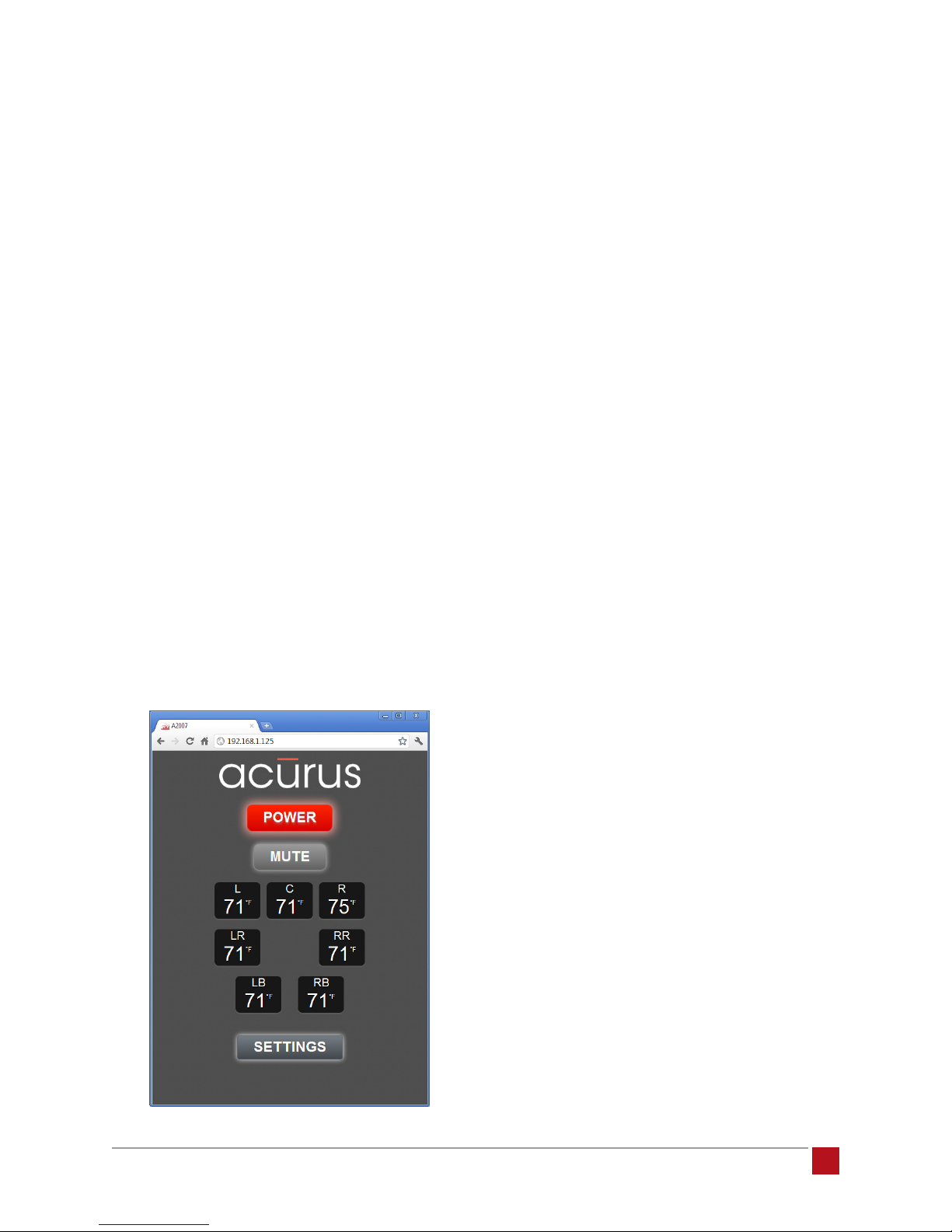
A view of the main control page similar to the one below
should appear (A2007 shown):
Power: This button performs the same function as the
front panel button on the amplier. The color of the but-
ton matches the light ring on the physical unit. It toggles
the unit between “on” and “standby” operation.
Mute: The mute button removes the audio output from
all channels of the amplier to the loudspeakers while
keeping the amplier channels powered on. In addi-
tion to providing a quick way to cut out audio in a room,
this feature is useful for breaking the signal path to help
diagnose possible sources of noise or other issues.
Channel Temperature Indicators: These indicators
provide real-time temperature information from each of
the channels. When in standby, or after initial power up,
these indicators will typically match room temperature
(within a few degrees). After several minutes of warm
up, when the channels have reached normal operating
temperature, these meters normally indicate channel
temperatures in the 95-110 degree F range. It is not unu-
sual to have up to 9 degrees of variation from channel-
to-channel. However, if one particular channel is running
outside this range, there may be an abnormal condition
such as a mismatch with a speaker load or service
adjustments that need to be made on the amplier by a
service technician. The number of Channel Temperature
Indicators in this view varies according to the number of
channels (2, 5 or 7) the amplier model provides.
©2012 Indy Audio Labs, LLC all rights reserved / Revision20120420
Document No. 1000571
Settings Button: The settings button opens the settings
page of the interface.
A 2 0 0 0 - S E R I E S A M P L I F I E R U S E R G U I D E
11
Page 12
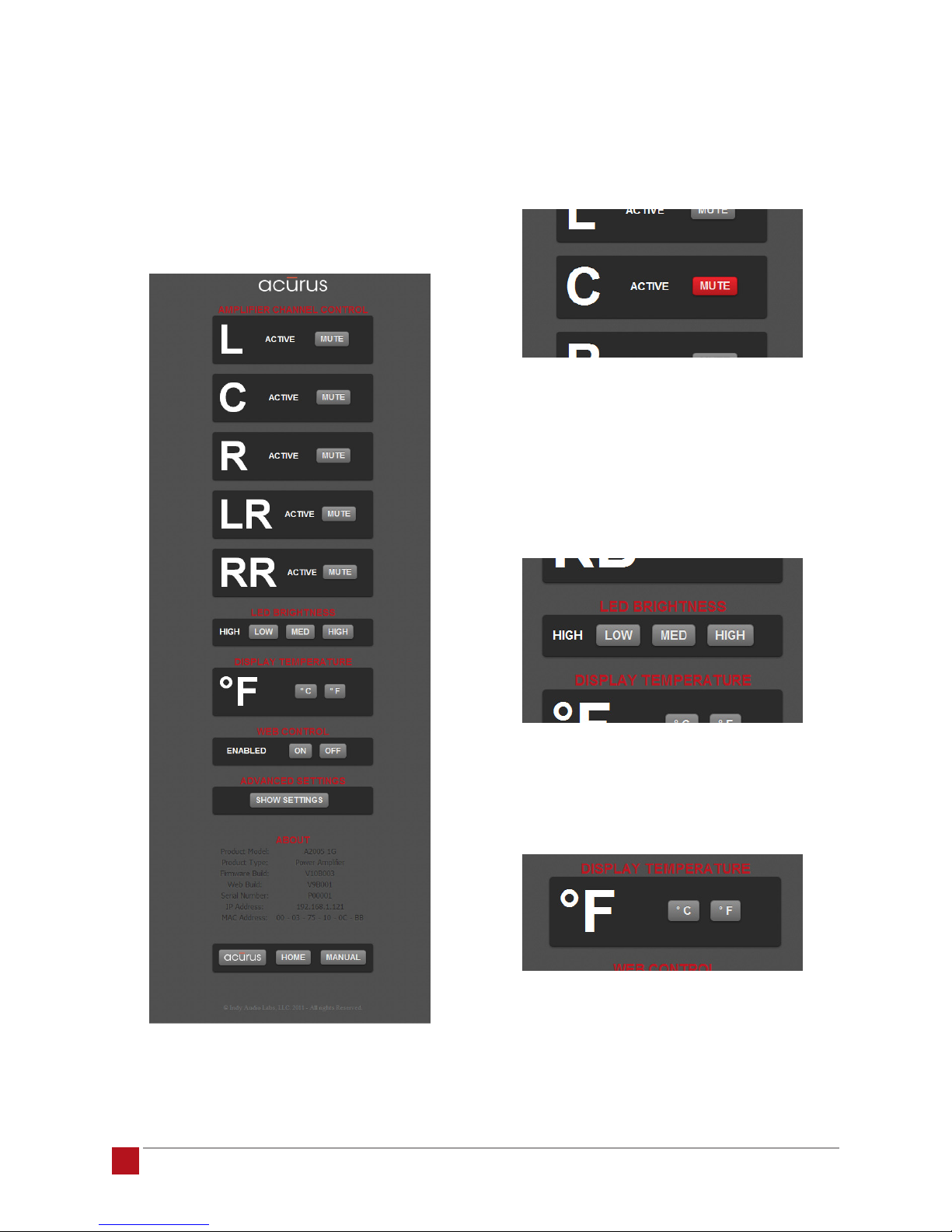
Settings Page: The top section of the settings page
shows each channel’s functional status (either “AC-
TIVE” or “PROTECT”) along with an individual channel
mute button. A channel reports PROTECT status if an
overtemp condition is encountered. The channel input is
automatically disconnected until the temperature sensed
is back within operating range.
Individual Channel Mute: The individual channel mutes
allow for simple troubleshooting and setup of individual
channels, particularly in a multi-channel surround setup.
When muted, the mute button illuminates red as below:
Front Panel Illumination Brightness Control: The front
panel status ring may be too bright for installations with
low lighting levels or more dimly illuminated companion
equipment. This section of the control interface allows
the default brightness level to be customized from high
to medium or low.
A 2 0 0 0 - S E R I E S A M P L I F I E R U S E R G U I D E
12
Temperature Display Units: This section toggles the
displayed temperature units from degrees F to degrees
C and vice versa.
©2012 Indy Audio Labs, LLC all rights reserved / Revision20120420
Document No. 1000571
Page 13
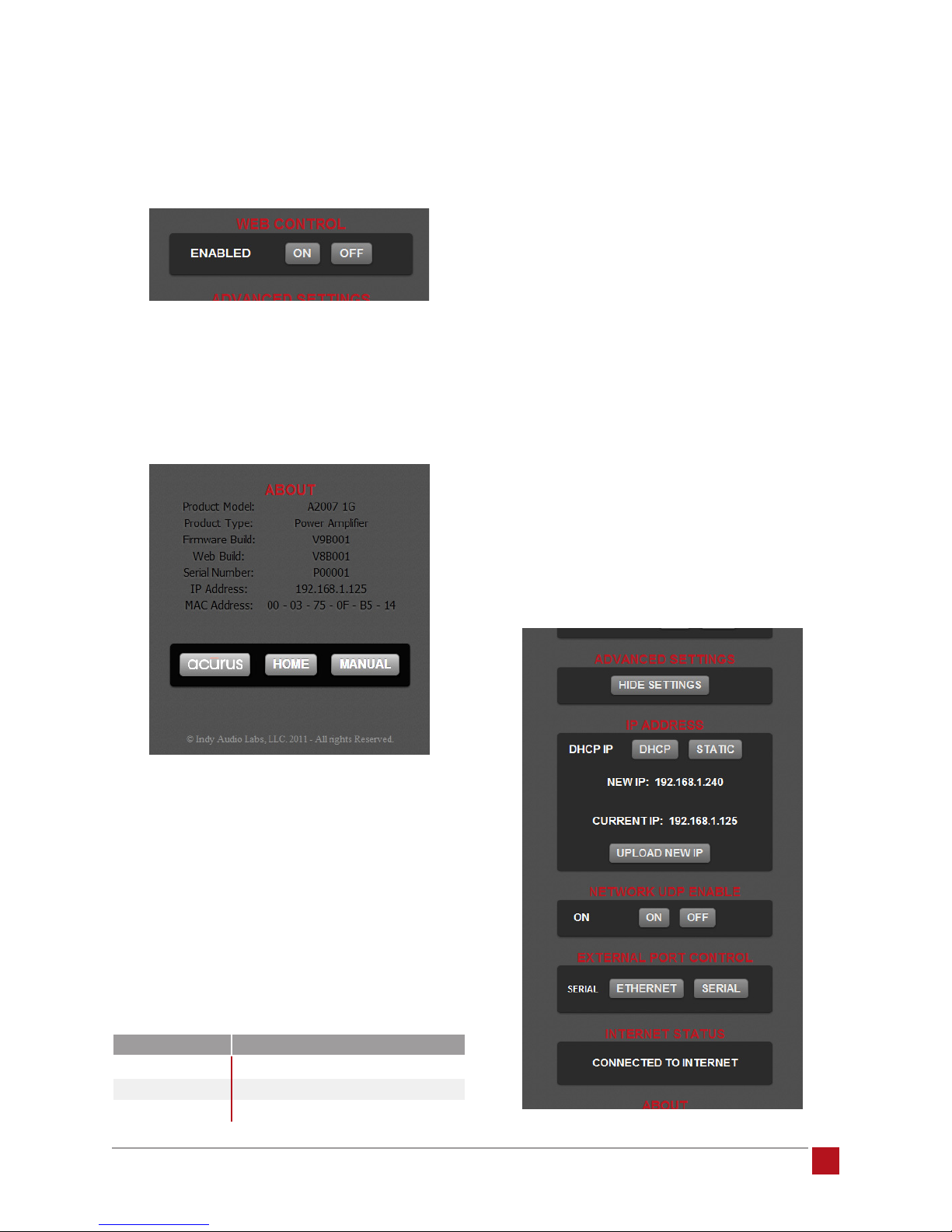
Web Control Enable: This on/off toggle is used for instal-
lations in which RS-232 or Ethernet commands are sent
from an external control system rather than via web
browser control.
About Information Section: This section contains useful
information such as product model, software version, IP
address, MAC address as well as buttons to view the
Acurus web page http://www.acurusav.com, and a but-
ton to view the latest version of the online user guide.
Press the “Static” button and enter a new static IP
address or simply hit “Enter” to accept the default
ip address. Then press the “Upload New IP” button
to change the current IP address to the new Static
IP address. The new Static IP address will be set
and the next time a browser is pointed to this IP ad-
dress, a permanent control link can be easily
created on the control device’s desktop.
2. Restoring automatic DHCP address assignment
- press the DHCP button to force the internal web
server to request a new address from the network
DHCP server.
3. Enabling/disabling UDP commands – prevents the
amplier from responding to Ethernet network com-
mands. In most cases, when no external Ethernet
controller is present, this can be turned off to add
an additional level of network security.
4. Changing external controller type - in cases where an
external Ethernet or Serial Control System is present,
either Ethernet or Serial control can be selected.
Advanced Settings: By selecting the “Show Settings”
button in the Advanced Settings section, advanced
information boxes appear that allow advanced control
functions and monitoring including:
1. Forcing a static IP address – used for creating
persistent links to the control page on a computer or
mobile device. (Note that an alternate method to ac-
complish this is to force a static IP for this MAC Ad-
dress in the local router.) The initial IP address of the
amplier is set to a default value per the table below:
5. Showing status on whether an internet connection
is present.
model default ip address
A2002
A2005
A2007
©2012 Indy Audio Labs, LLC all rights reserved / Revision20120420
Document No. 1000571
192.168.1.250
192.168.1.241
192.168.1.240
A 2 0 0 0 - S E R I E S A M P L I F I E R U S E R G U I D E
13
Page 14
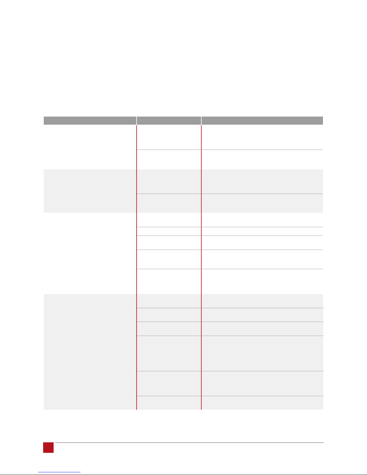
problem resolution
From time to time, problems may occur. The following ta-
ble is intended to help categorize and solve issues that
may arise. Of course, if problems persist, do not hesitate
to call your local dealer or Acurus Customer Service.
Troubleshooting Table
problem or symptom possible causes recommendations
Amplifier does not power on –
no front panel lights
Amplifier powers on with red standby
light but does not switch on with blue
light indicator via web control
Amplifier switches on (blue indicator)
but does not produce audio
Not all amplifier channels appear
to be working
AC not connected • Check that power cord is connected at the wall and at the
Blown or missing mains fuse Check fuse compartment in back of unit near AC inlet.
Control device not connected
to local network
Amplifier disconnected from
local network
Loudspeakers disconnected Check loudspeaker connections at the amplifier and at the
Pre-amp not powered on Check preamp power status.
Pre-amp not connected
properly
Source device disconnected • Check connections between source device and pre-amp.
Web control global or
channel mutes active
Shorted or open speaker leads Check loudspeaker connections at the amplifier and at the
Pre-amp not connected
properly
Loudspeaker problem Disconnect problem loudspeaker and reconnect it to a known
Preamp or source device
surround mode problem
(applies primarily to
A2005, A2007)
Web control global or
channel mutes active
Blown channel protection
fuse(s)
back of the unit.
• Check that switched AC outlets are on.
• Check that power conditioner is on (if applicable).
Replace fuse and retest. If problem persists, refer unit to
service personnelle.
• Check to ensure control device is connected to the local
network and not another neigboring network.
• Check to ensure that all network routers and switches are
powered up and active.
Check network activity light – if not illuminated green, check
opposite end of cable. If cable is plugged in and switch or
router shows activity indication, replace network cable.
speaker terminals. Look for frayed or disconnected leads.
Check to ensure amplifier inputs are connected directly from
corresponding pre-amp outputs via good RCA cables.
• Try using an alternate source device to eliminate the
possibility of a pre-amp problem.
Using web control, check mute button states on main view
and advanced views. Alternately, reset AC power to the unit to
reset the mute states. Note that with DHCP control, this may
reset the unit IP address.
speaker terminals. Look for frayed or disconnected leads.
Check to ensure amplifier inputs are connected directly from
corresponding pre-amp outputs via good RCA cables.
good amplifier channel.
Check that speaker sound is supported in the processing
mode that is active. For example, a center channel speaker
will be silent in Dolby Digital 2.0 mode. Likewise, for speech
playback, often the left and right front speakers will be silent
in Dolby Pro Logic mode. Refer to the information that came
with the preamp or source device.
Using web control, check mute button states on main view
and advanced views. Alternately, reset AC power to the unit to
reset the mute states. Note that with DHCP control, this may
reset the unit IP address.
Can sometimes occur after faulty connection to good
loudspeaker OR good connection to faulty loudspeaker.
A 2 0 0 0 - S E R I E S A M P L I F I E R U S E R G U I D E
14
©2012 Indy Audio Labs, LLC all rights reserved / Revision20120420
Document No. 1000571
Page 15

problem or symptom possible causes recommendations
Amplifier sound is garbled
or distorted
Hum persists only when amplifier
is on – goes away in standby
Cannot control amplifier from mobile
device or computer
Turning on pre-amp does not
automatically turn on amplifier
Amplifier runs for a while then one
or more channels cut out
Amplifier runs hot even at low
audio levels
Shorted or open speaker leads Check loudspeaker connections at the amplifier and at the
Pre-amp not connected
properly
Loudspeaker problem Disconnect problem loudspeaker and reconnect it to a
Partially connected or faulty
RCA input cable
Bad AC ground connection • Check to ensure the original 3-conductor heavy-guage
Cable or Sattelite TV connection
causing hum
Control device not connected
to local network
Amplifier disconnected from
local network
Incorrect IP address input to
controlling computer or mobile
device browser
Trigger cable missing or plug
not seated fully in trigger
in jack
Trigger voltage outside
acceptable range
Faulty (shorted) loudspeaker
connection
Faulty loudspeaker Remove loudspeaker and re-check channel with a
Ventillation inadequate Check to ensure that sides, rear and top of unit have at least
Low impedance
loudspeaker load
Faulty (shorted)
loudspeaker connection
Faulty loudspeaker Remove loudspeaker and re-check channel with a
speaker terminals. Look for frayed or disconnected leads.
Check to ensure amplifier inputs are connected directly from
corresponding pre-amp outputs via good RCA cables.
known good amplifier channel.
• Check for RCA plugs not seated completely in jacks
• Isolate and replace faulty cable.
power cord that shipped with your Acurus is used for
the amplifier.
• Try a different power outlet in case the wall outlet ground
is defective.
• Attempt to power the system from a single AC outlet
to minimize ground loops.
Verify source by disconnecting incoming cable line or satellite
dish cable to see if hum disappears. If this is the source, then
hum will dissappear when the cable is disconnected from the
system. If so, us an isolation transformer (or Mondial Magic
Box) at each of the cable and/or satellite inputs.
• Check to ensure control device is connected to the local
network and not another neigboring network.
• Check to ensure that all network routers and switches are
powered up and active.
Check network activity light – if not illuminated green, check
opposite end of cable. If cable is plugged in and switch or
router shows activity indication, replace network cable.
Check IP address on host router or using an IP scan tool.
If IP address is correct, perform full power reset of amplifier
(remove and reinsert AC inlet cord).
Check trigger cable connections and re-test.
Refer to pre-amp information to ensure the trigger output falls
into the range 5-24Vdc.
Check loudspeaker connections at the amplifier and at the
speaker terminals. Look for frayed leads touching each other
or touching chassis metal.
known-good loudspeaker.
2 inches of air space and that air can flow in and out of
space around amplifier installation.
Check to ensure that the loudspeakers are greater than or
equal to 4 ohms nominal impedance.
Check loudspeaker connections at the amplifier and at the
speaker terminals. Look for frayed leads touching each other
or touching chassis metal.
known-good loudspeaker.
Obtaining Additional Help
For problems not addressed here, have the model, serial
number and date of purchase of your Acurus compo-
©2012 Indy Audio Labs, LLC all rights reserved / Revision20120420
Document No. 1000571
nent handy and contact your local dealer or contact
Acurus Customer Service at 1-866-781-7284 M-F, 9AM
to 5PM E.S.T. or email [email protected].
A 2 0 0 0 - S E R I E S A M P L I F I E R U S E R G U I D E
15
Page 16

technical specifications
All Models
A2002 only
A2005 only
A2007 only
Power output 200W into 8Ω, multiple channels driven
THD < 0.03%, multiple channels driven, full power, 8 ohms
Frequency response 20Hz to 20kHz ± 0.1dB
Tim/dim distortion < 0.003%
S/N >106 dB, A-weighted
Damping factor 500, 8Ω @50Hz
Input sensitivity 1W: 100mV
Input impedance 20kΩ
Recommended loudspeaker impedance range 4-8 ohms nominal
DC offset (output) <3mV
Rail voltage +/-80Vdc
THX Ultra2 Certified
Number of channels driven for
continuous power spec
Power consumption Standby: 1W
Unit dimensions (LxWxH) 13.5 x 17 x 5 (inches), 34 x 43 x 13 (cm)
Rack height 3 RU
Unit weight 29lbs (13kg)
Finish Black anodized aluminum with laser-etched markings
Shipping carton (LxWxH) 22 x 18 x 10 (inches), 56 x 46 x 25 (cm)
Carton weight 35lbs (16kg)
Number of channels driven for
continuous power spec
Power consumption Standby: 1W
Unit dimensions (LxWxH) 15 x 17 x 9 (inches), 38 x 43 x 23 (cm)
Rack height 5 RU
Unit weight 47lbs (21kg)
Finish Black anodized aluminum with laser-etched markings
Shipping carton (LxWxH) 22 x 20 x 16 (inches), 56 x 51 x 41 (cm)
Carton weight 55lbs (25kg)
Number of channels driven for
continuous power spec
Power consumption Standby: 1W
Unit dimensions (LxWxH) 15 X 17 x 9 (inches), 38 x 43 x 23 (cm)
Rack height 5 RU
Unit weight 52Lbs (24kg)
Finish Black anodized aluminum with laser-etched markings
Shipping carton (LxWxH) 22 X 20 x 16 (inches), 56 x 51 x 41 (cm)
Carton weight 60Lbs (27kg)
300W into 4Ω, multiple channels driven
< 0.05%, multiple channels driven, full power, 4 ohms
10Hz to 70kHz +0,-3dB
200W: 1.42V
2 channels
Idle: 23W
Max: 1200W
5 channels, music at 50% duty cycle
4 channels, sine wave, 8 ohms
Idle: 75W
Max: 1440W
7 Channels, music at 50% duty cycle
4 Channels, sine wave, 8 ohms
Idle: 85W
Max: 1440W
A 2 0 0 0 - S E R I E S A M P L I F I E R U S E R G U I D E
16
©2012 Indy Audio Labs, LLC all rights reserved / Revision20120420
Document No. 1000571
Page 17
A2002 Architects and Engineering Specifications
The audio amplier shall provide 2 output channels and
produce 200W continuous power into 8 ohms, each
channel driven.
A2007 Architects and Engineering Specifications
The audio amplier shall provide 7 output channels and
produce 200W continuous power into 8 ohms, each
channel driven.
The unit shall include a 10/100 Ethernet port and an
RS-232 port for remote control and status monitoring.
A 12V Trigger port shall be included to allow remote on/
off triggering by an external preamp or power control
center. The amplier shall have an internal web server
which delivers a browser-compatible GUI. This GUI shall
allow for remote control and monitoring via computer or
mobile device/An RS-232 port.
The unit shall have adjustable front panel lighting levels
for dimly lit environments or bright rooms. The rear panel
shall have gold-plated input RCA connectors and gold-
plated 60A-rated loudspeaker binding posts.
The unit shall contain a worldwide congurable power
supply, and be compliant with FCC Part 15 and CE
requirements.
The unit shall be the Acurus A2002.
A2005 Architects and Engineering Specifications
The audio amplier shall provide 5 output channels and
produce 200W continuous power into 8 ohms, each
channel driven.
The unit shall include a 10/100 Ethernet port and an
RS-232 port for remote control and status monitoring. A
12V Trigger port shall be included to allow remote on/
off triggering by an external preamp or power control
center. The amplier shall have an internal web server
which delivers a browser-compatible GUI. This GUI shall
allow for remote control and monitoring via computer or
mobile device/An RS-232 port.
The unit shall have adjustable front panel lighting levels
for dimly lit environments or bright rooms. The rear panel
shall have gold-plated input RCA connectors and gold-
plated 60A-rated loudspeaker binding posts.
The unit shall contain a worldwide congurable power
supply, and be compliant with FCC Part 15 and CE
requirements.
The unit shall be the Acurus A2007.
The unit shall include a 10/100 Ethernet port and an
RS-232 port for remote control and status monitoring. A
12V Trigger port shall be included to allow remote on/
off triggering by an external preamp or power control
center. The amplier shall have an internal web server
which delivers a browser-compatible GUI. This GUI shall
allow for remote control and monitoring via computer or
mobile device/An RS-232 port.
The unit shall have adjustable front panel lighting levels
for dimly lit environments or bright rooms. The rear panel
shall have gold-plated input RCA connectors and gold-
plated 60A-rated loudspeaker binding posts.
The unit shall contain a worldwide congurable power
supply, and be compliant with FCC Part 15 and CE
requirements.
The unit shall be the Acurus A2005.
©2012 Indy Audio Labs, LLC all rights reserved / Revision20120420
Document No. 1000571
THX and Ultra2 are trademarks of THX Ltd.
THX is registered in some jurisdictions. All rights reserved.
A 2 0 0 0 - S E R I E S A M P L I F I E R U S E R G U I D E
17
Page 18

design notes
The Acurus A2000 series was designed by engineers
at Indy Audio Labs to deliver audio experiences un-
matched by any other products in their category.
While not an easy task, here’s how we do it.
To achieve such a high level of perfection in a high-
performance audio amplier, a reliable, fast, efcient
amplier topology is required. The Acurus A2000 series
uses high-bandwidth, matched On Semiconductor®
output transistors in a fully-discrete class A/B design,
input-to-output. Unlike many other discrete topologies
in this class of amplier, our design remains symmetric
from the very rst current-mirror input stage on through
to the output. No op-amps are used in the signal path
- only precision, low-noise semiconductors. The result
is an audio output that nearly perfectly mirrors the input
signal characteristics and dynamics. Soundstage is dis-
tinct, broad and detailed. High-frequency transients are
crisp and clean. Bandwidth is beyond wide, spanning
from less than 10Hz on the low end to more than 70 kHz
at the top, well beyond the range of most sources, let
alone human hearing. Low-frequencies are reproduced
authoritatively due in no small part to the big power
supply which features a massive toroidal transformer
and 46,000 microfarads of power supply capacity even
in the basic A2002. The 5 and 7-channel models more
than double that capacitance. In fact, all A2000 series
ampliers are capable of delivering current peaks to a
speaker load exceeding 18 Amps!
However, we don’t feel it’s not enough for engineers to
build a unit which measures well on the test bench. To
make every one of these ampliers sound as good in
your home as the very rst ones we hand-built in the
lab, we have the circuit boards stuffed and inspected by
both hand and machine and nal assemble each here
in the USA in our factory in southern Indiana. We take
advantage of a manufacturing environment designed
to make not only high-performance audio products, but
also precision devices for demanding medical, military
and communications customers. Within our products,
carefully inspected printed circuit boards feature thick
copper layers and are populated with tight-tolerance
(1%) resistors and lm capacitors throughout the signal
path. Internal wiring is done by hand using high-tem-
perature and Teon-coated materials. Transformers are
custom-wound to our specications and made in North
America with virgin materials.
The solid look of these ampliers should come as no
surprise. The Acurus A2000 series metalwork is done
right in Indiana at some of the same precision metal
suppliers building certied componentry for IRL (Indy
Racing League) cars. Thick-gauge steel forms the
framework for the Acurus-standard anodized Aluminum
alloy faceplate, top cover and side heat sinks. The frame
is powder-coated white to protect it, to make assembly
easier and to make the rear panel easier to read during
installation in the typical dimly-lit home AV equipment
rack. Unlike most of our competitors, externally mounted
heat sinks on all models draw heat away from the interior
of the chassis using natural convection most effectively,
especially in a rack mount scenario. Custom rack ears
make system-integration smooth. Mechanical details
are important to us - down to the laser-etched logo and
model information on the custom-tooled front panel.
Even the power switch was designed from the ground-
up by Acurus engineers for long-life, good illumination
and a solid feel.
When an Acurus amp initially “comes to life” on the as-
sembly line, we make sure it’s rst days are its most dif-
cult. Once an amplier is fully-assembled and quality-
checked, it is tuned on the assembly line for optimal
performance prior to burn-in, tested and then re-tested
once again. Our tough burn-in tests not only prepare the
amplier for rst use but also expose it to worst-case op-
erational loads, exceeding the most challenging home
environments we can imagine. Our goal is to make sure
each amplier we build lasts as long as legacy Acurus
amps built more than a decade ago.
While we’re proud of what we achieved with the Acurus
A2000 series, we recognize our own human bias can
easily get in the way of objectivity and fair comparisons.
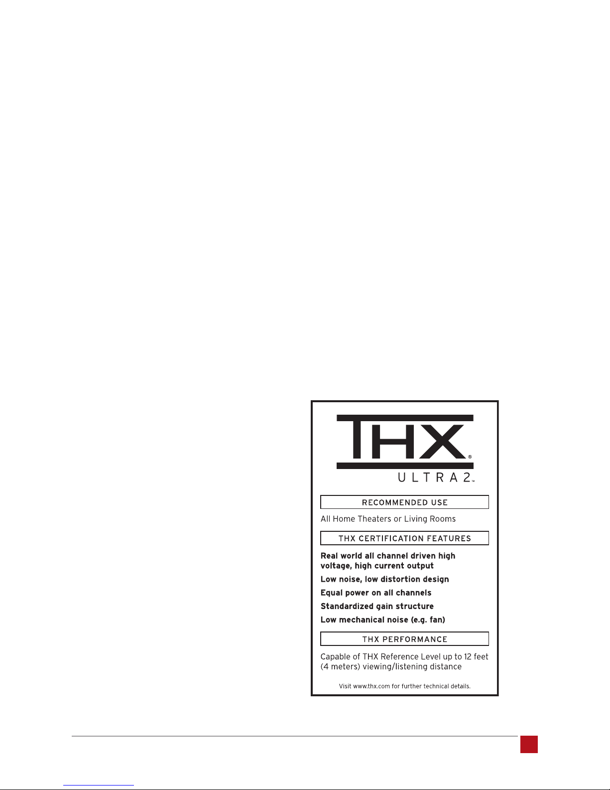
That’s why we chose to engage the assistance of THX to
certify our Acurus A2000 series to their stringent Ultra2
requirements. THX Ultra2 is designed for home audio
enthusiasts that demand peak performance. It offers
A 2 0 0 0 - S E R I E S A M P L I F I E R U S E R G U I D E
18
©2012 Indy Audio Labs, LLC all rights reserved / Revision20120420
Document No. 1000571
Page 19

uncompromised playback of multi-channel movies, mu-
sic and games. It incorporates new features and power
requirements for premium Home Theater receivers,
pre-ampliers, power ampliers and speakers capable
of distributing an optimal soundstage across wide view-
ing areas in dedicated Home Theaters. We’re happy to
report that our ampliers pass with ying colors.
WARRANTY
U.S. and Canada:
The Warranty below is valid only for sales to consumers
in the United States or Canada.
The manufacturer warrants this product to be free from defects in
materials and workmanship (subject to the terms set forth below)
for a period of five (5) years from the date of purchase. During
the Warranty period, the manufacturer will repair or replace (at the
manufacturer’s option) this product or any defective parts.
But in today’s world, you may point out, it’s not enough
to simply deliver great sound. You want control of the
experience. We recognized that too when we designed
the Acurus A2000 series. That’s why we developed an
entirely new technology which gives you total control of
your system - using our built-in proprietary web control.
With our web control, you can monitor and control all
system features and functions through an existing home
network, all with a smart phone, computer, or almost
any device with a web browser. No need for yet another
IR remote on the coffee table. We put the control where
you want it - in your hands and in your pocket. As future
updates become available, these amps can be updated
in both software and hardware. There are no apps to
download since all the software, including the user inter-
face, resides in the unit itself.
So, see your local dealer and ask for a demo to under-
stand why we feel, and others agree, that the Acurus
A2000 series delivers an audio experience unmatched
by any others in its class.
To obtain technical support and/or warranty service, you may either:
(a) contact the authorized Acurus dealer from which you purchased
this product or (b) call INDY AUDIO LABS at 1-866-559-5113
(toll free) or (c) email INDY AUDIO LABS support at support@
indyaudiolabs.com. If you choose to call INDY AUDIO LABS directly
we strongly suggest that you choose the technical support option as
the majority of customer problems can be solved over the phone.
If technical support is unable to solve the problem, they will advise
as to whether the preferred route to obtain warranty service is to
return the product to the INDY AUDIO LABS authorized dealer from
which you purchased the product or to return the product directly
to the manufacturer, freight paid, for repair. If returning the product
you will need to obtain a Return Authorization from Indy Audio Labs
and ship this product in either its original packaging or packaging
affording an equal degree of protection.
Proof of purchase in the form of a bill of sale or receipted invoice
(which is evidence that this product is within the Warranty period)
must be presented or included in order to obtain Warranty service.
This Warranty is invalid if (a) the factory-applied serial number has
been altered or removed from this product or (b) this product was not
purchased from an INDY AUDIO LABS authorized dealer. You may call
1-866-559-5113 (choose the INDY AUDIO LABS customer service
option) to confirm that you have an unaltered serial number and/or
that you purchased from a INDY AUDIO LABS authorized dealer.
This Warranty is only valid for the original purchaser and will
automatically terminate prior to expiration if this product is sold or
otherwise transferred to another party.
This Warranty does not cover cosmetic damage or damage due to
misuse, abuse, negligence, acts of God, accident, commercial use or
modification of, or to any part of, the product. This Warranty does not
cover damage due to improper operation, maintenance or installation,
or attempted repair by anyone other than the manufacturer or an
INDY AUDIO LABS dealer which is authorized to do INDY AUDIO LABS
warranty work. Any unauthorized repairs will void this Warranty.
This Warranty does not cover product sold AS IS or WITH ALL FAULTS.
Acurus A2000 Series – 2012 CES Innovations Award
Honoree – Audio Components Category
©2012 Indy Audio Labs, LLC all rights reserved / Revision20120420
Document No. 1000571
REPAIRS OR REPLACEMENTS AS PROVIDED UNDER THIS
WARRANTY ARE THE EXCLUSIVE REMEDY OF THE CONSUMER.
THE MANUFACTURER SHALL NOT BE LIABLE FOR ANY INCIDENTAL
OR CONSEQUENTIAL DAMAGES FOR BREACH OF ANY EXPRESS
OR IMPLIED WARRANTY ON THIS PRODUCT. EXCEPT TO THE
EXTENT PROHIBITED BY LAW, THIS WARRANTY IS EXCLUSIVE
AND IN LIEU OF ALL OTHER EXPRESS AND IMPLIED WARRANTIES
WHATSOEVER, INCLUDING BUT NOT LIMITED TO, THE WARRANTY
OF MERCHANTABILITY AND FITNESS FOR A PRACTICAL PURPOSE.
Applicable Territories: Some states and foreign territories do not allow
the exclusion or limitation of incidental or consequential damages or
implied warranties so the above exclusions may not apply to you.
This Warranty gives you specific legal rights, and you may have
other rights, which vary from state to state and territory to territory. The
warranty on this product if it is sold to a consumer outside of the United
States or Canada shall comply with applicable law and shall be the
sole responsibility of the distributor that supplied this product. To obtain
any applicable warranty service, please contact the dealer from which
you purchased this product, or the distributor that supplied this product.
A 2 0 0 0 - S E R I E S A M P L I F I E R U S E R G U I D E
19
Page 20
about acurus and
indy audio labs
Acurus and Aragon are wholly owned brands of Indy Audio
Labs. Acurus was originally founded in 1993 by Mondial
designs as a more affordable alternative to its, by then,
critically acclaimed Aragon brand.
Indy Audio Labs was founded in late 2008 by three
audio engineers and a physicist who saw a vision for an
affordable set of home entertainment products which bring
together professional-grade audio performance, state-of-
the-art control and connectivity, and simplied access to
today’s content sources.
Like it’s predecessor, Mondial, Indy Audio Labs designs
and manufactures all of its audio components in the USA
using custom fabricated parts and assemblies. Indy Audio
Labs prides itself on remaining true to the original mission
of Acurus – delivering “Accuracy from the USA”.
www.indyaudiolabs.com
5225 Exploration Drive
Indianapolis, IN 46241
T 866.559.5113
F 866.719.8516
 Loading...