

Page 1
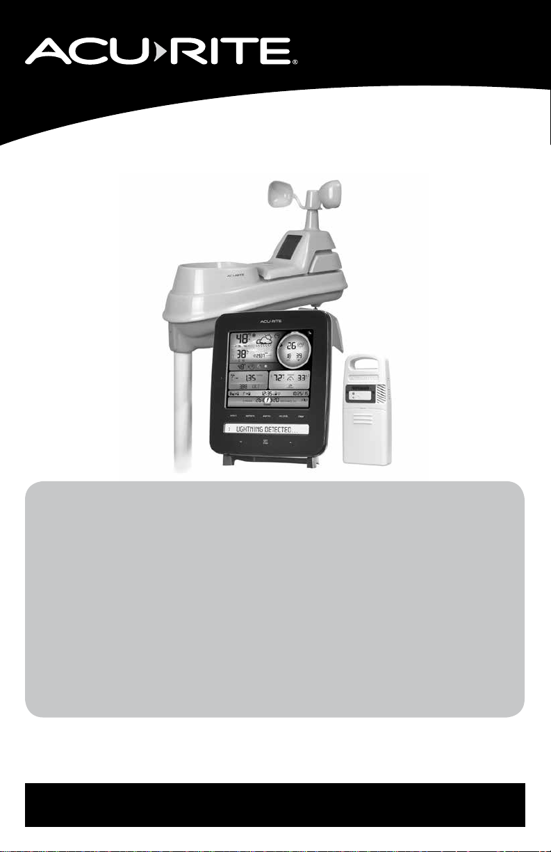
Instruction Manual
Weather Station with Lightning Detector
models 01022, 02080, 06046
CONTENTS
Unpacking Instructions ............... 2
Package Contents ...................... 2
Product Registration ................... 2
Features & Benets: Lightning Sensor .. 3
Features & Benets: 5-in1 ........... 4
Features & Benets: Display........ 5
Setup ........................................ 9
Lightning Sensor Setup ............... 9
5-in-1 Sensor Setup ...................10
Display Setup ...........................11
Set the Time, Date & Units .........12
Backlight Settings ......................12
Placement Guidelines ................13
5-in-1 Sensor Installation............15
Using the Weather Center .........16
Rainfall Tracking .......................18
Weather Ticker .........................19
Programmable Alarms.............. 20
Troubleshooting ....................... 22
Care & Maintenance................ 24
Calibration .............................. 24
Specications........................... 26
FCC Information ...................... 26
Customer Support .................... 27
Warranty................................. 27
Questions? Contact Customer Support at
(877) 221-1252 or visit www.AcuRite.com.
SAVE THIS MANUAL FOR FUTURE REFERENCE.
Page 2
Congratulations on your new AcuRite product. To ensure the best
possible product performance, please read this manual in its entirety
and retain it for future reference.
Unpacking Instructions
Remove the protective lm that is applied to the LCD screen prior to using this
product. Locate the tab and peel off to remove.
Package Contents
1. Display with Tabletop Stand
2. 5-in-1 Sensor
3. Lightning Sensor
4. Sensor Mounting Bracket
5. Mounting Hardware
6. Power Adapter
7. Instruction Manual
PRODUCT MUST BE REGISTERED
IMPORTANT
TO RECEIVE WARRANTY SERVICE
PRODUCT REGISTRATION
Register online to receive 1 year warranty protection
www.AcuRite.com
2
Page 3
Features & Benets
1
2
3
I=
4
5
NOTE: Under no circumstances shall the Lightning Detector, Chaney Instrument
Co. or the Primex Family of Companies be held responsible for any damages
whatsoever that may result from the use of or inability to use this product, including
without limitation any indirect, incidental, special, exemplary or consequential
damages, which are expressly disclaimed. This disclaimer of liability applies to
any damages or injury caused by any failure of performance, error, omission,
inaccuracy, interruption, deletion, defect, delay in operation or transmission
software virus, communication failure, theft or destruction or unauthorized access
to, alteration of, or use of the product, whether for breach of contract, tortuous
behavior (including, without limitation, strict liability), negligence, or under any
other cause of action, to the fullest extent permissible by law. This does not affect
any statutory rights which may not be disclaimed. The contents of this product,
including all lightning and weather data are provided “as is” and without warranty
or condition of any kind, express or implied, including, without limitation, any
warranty of merchantability or tness for a particular purpose. Chaney Instrument
Co. & the Primex Family of Companies do not warrant that this product or the
data that it provides will be free of errors, interruptions, viruses or other harmful
components. Chaney Instrument Co. & the Primex Family of Companies do not
warrant the accuracy or reliability of any lightning strike alerts, weather data or
other information provided by the product. Chaney Instrument Co. & the Primex
Family of Companies reserve the right to alter the product or withdraw it from the
market at its sole discretion.
l!!I
~;
[
,...,
6
7
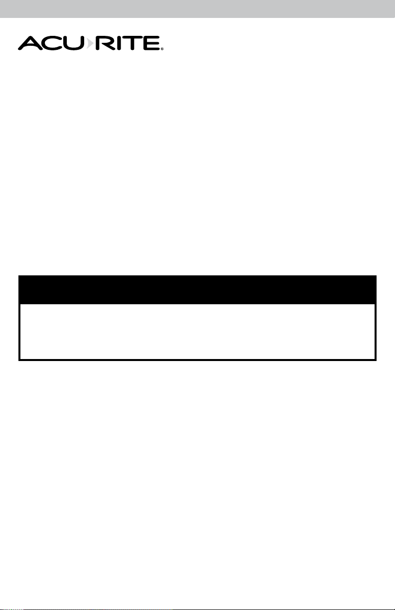
LIGHTNING SENSOR
1. Integrated Hanger
For easy placement.
2. Wireless Signal Indicator
Flashes when data is being
sent to the companion unit.
3. Interference Indicator
Flashes when interference is
detected (see page 14).
4. A-B-C Switch
ID code that must match
display’s A-B-C switch to ensure
units synchronize.
5. Battery Compartment
6. Lightning Strike Indicator
Indicates a lightning strike has
occurred within 25 miles (40 km).
7. Battery Compartment Cover
3
Page 4
Features & Benets
7
1
2
9
11
6
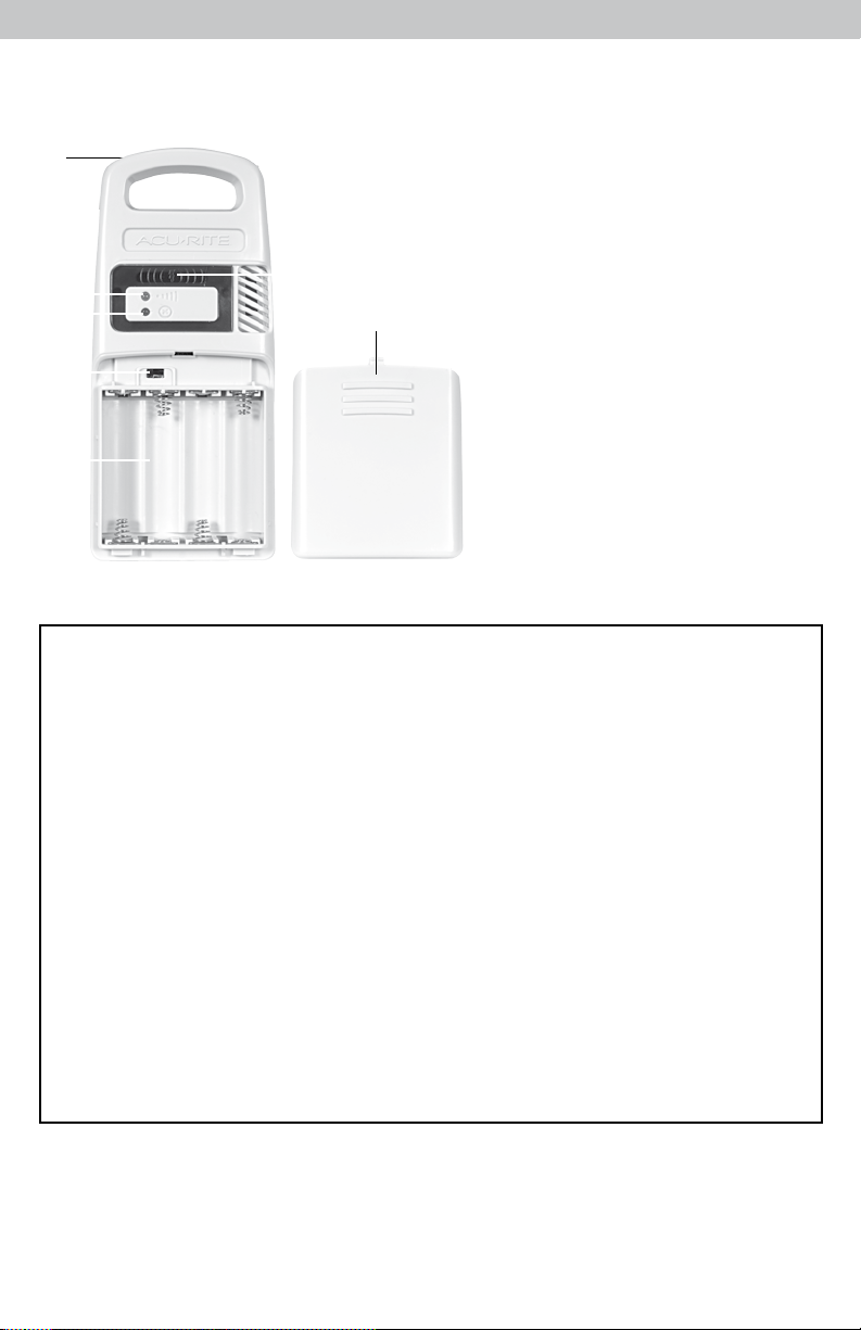
5-in-1 SENSOR
1. Rainfall Collector Funnel
2. Solar Cell Panel
Converts sunlight into power to run
internal aspirating fan.
Internal Aspirating Fan
(not shown)
Draws ambient air into
sensor to reduce solar radiation
heating, resulting in more accurate
temperature measurement.
3. A-B-C Switch
ID code that must match display’s
A-B-C switch to ensure units
synchronize.
4. Battery Compartment
4
3
5
8
10
5. Temperature & Humidity Sensors
(internal)
6. Mounting Point
7. Wind Speed Anemometer
8. Wind Direction Vane
9. Mounting Bracket
10. Mounting Hardware
Includes 5 anchors & the following
screws:
Qty Diameter Length
5 #4 3/4”
1 #4 1/2”
1 #6 1/2”
11. Debris Filter
Pre-installed to prevent debris from
entering the rain gauge.
4
Page 5
Features & Benets
1
2 3 4 65 7 3 8
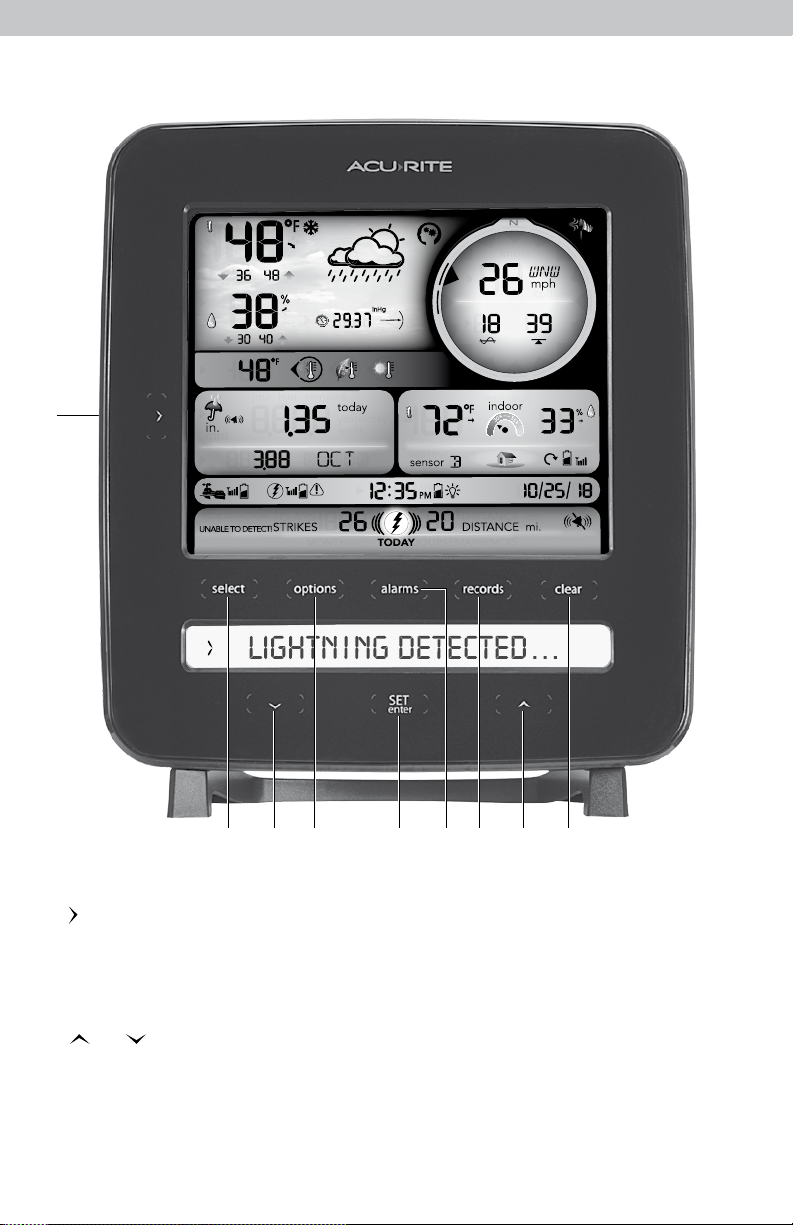
FRONT OF DISPLAY
1. Button
>
Press to view rainfall records (see page 18).
2. select Button
Press to cycle through available
readings and access options, alarms
and records menu.
3. and Buttons
A V
For setup preferences and manually
cycling through Weather Ticker messages
(when display is not connected to
additional sensors). For manually cycling
add-on sensor data (when display is
connected to additional sensors).
4. options Button
For calibration and setup preferences.
SET
5.
6. alarms Button
7. records Button
8. clear Button
Button
enter
For setup preferences.
For alarm setup preferences.
Press to view historical records for
reading selected.
Press to clear selected record.
5
Page 6
Features & Benets
FRONT OF DISPLAY
41 4039 38 37 34 36
1
2
3
4
5
6
7
8
9
10
11
12
13
14
15
16
35
34
33
32
31
30
29
28
27
26
25
24
23
8
17 18 14 19 222120
6
Page 7

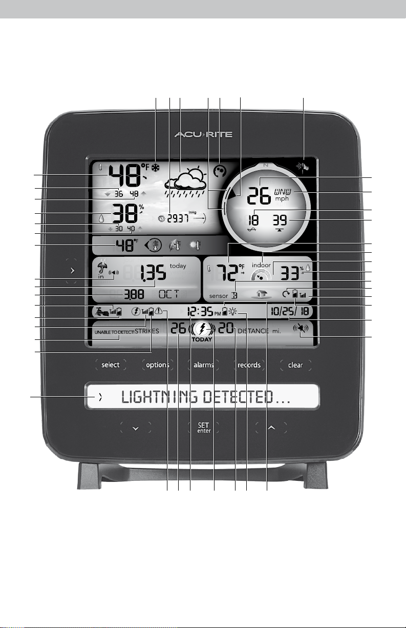
1. Current Outdoor Temperature
Arrow indicates direction temperature
is trending.
2. Outdoor Low Temperature Record
Lowest temperature recorded since
midnight.
3. Outdoor High Temperature Record
Highest temperature recorded since
midnight.
4. Current Outdoor Humidity
Arrow indicates direction humidity
is trending.
5. Outdoor Low Humidity Record
Lowest humidity recorded since midnight.
6. Outdoor High Humidity Record
Highest humidity recorded since midnight.
7. Weather Select
Heat Index calculation displays when
temperature is 80°F (27°C) or higher.
Dew Point calculation displays when
temperature is 79°F (26°C) or below.
Wind chill calculation displays when
temperature is 40°F (4°C) or lower.
8. Alarm ON Indicator
Indicates alarm is activated to emit an
audible alert when conditions exceed
your presets (see page 20).
9. Rainfall
Displays most recent rainfall total
(today, yesterday or this week).
10. Rainfall History
Displays historical rainfall totals
(see page 18).
11. 5-in-1 Sensor Signal Strength
12. 5-in-1 Sensor Low Battery Indicator
13. Lightning Sensor Signal Strength
14. Interference Indicator
Flashes when interference is detected
(see page 14).
15. Lightning Sensor Low Battery Indicator
16. Weather Ticker
Streams real-time data (see page 19).
17. Strike Counter
Displays most recent total of lightning
strikes that has been detected (today,
this week, this month).
18. Clock
Automatically updates for Daylight
Saving Time.
19. Lightning Strike Indicator
Indicates a lightning strike has
occurred within 25 miles.
20. Estimated Distance to Storm Front
Updates with latest lightning strike
detected today.
21. Icon
v
Indicates display is in auto-dimming
brightness mode (see page 12).
22. Display Low Battery Indicator
23. Date
24. Add-on Sensor Low Battery Indicator
If applicable (see page 17).
25. Add-On Sensor Signal Strength
If applicable (see page 17).
26. Auto-Cycle Indicator
Indicates auto-cycle mode is enabled.
If applicable (see page 17).
27. Add-On Sensor Indicator
If applicable (see page 17).
28. Current Humidity for #27 or #30
Arrow icon indicates direction humidity
is trending.
29. Humidity Level Indicator
Indicates a high, low, or ideal humidity
comfort level.
30. Indoor Indicator
Indicates indoor (display) conditions are
being shown.
31. Current Temperature for #27 or #30
Arrow icon indicates direction temperature
is trending.
32. Peak Wind Speed
Highest speed from the last 60 minutes.
33. Average Wind Speed
Average wind speed over the past 2 minutes.
34. Current Wind Direction
35. Current Wind Speed
36. Wind Speed Alert Indicator
Activates when wind speed is over 32 mph.
37. Learning Mode Icon
Disappears after weather forecast
self-calibration is complete (see page 16).
38. Previous 2 Wind Directions
39. 12 to 24 Hour Weather Forecast
Self-Calibrating Forecasting pulls data from
your 5-in-1 sensor to generate your
personal forecast.
40. Barometric Pressure
Arrow icon indicates direction pressure
is trending.
41. Freeze Alert Indicator
Indicates temperature is below freezing
(32°F; 0°C).
7
Page 8
1
2
3
8
7
6
4
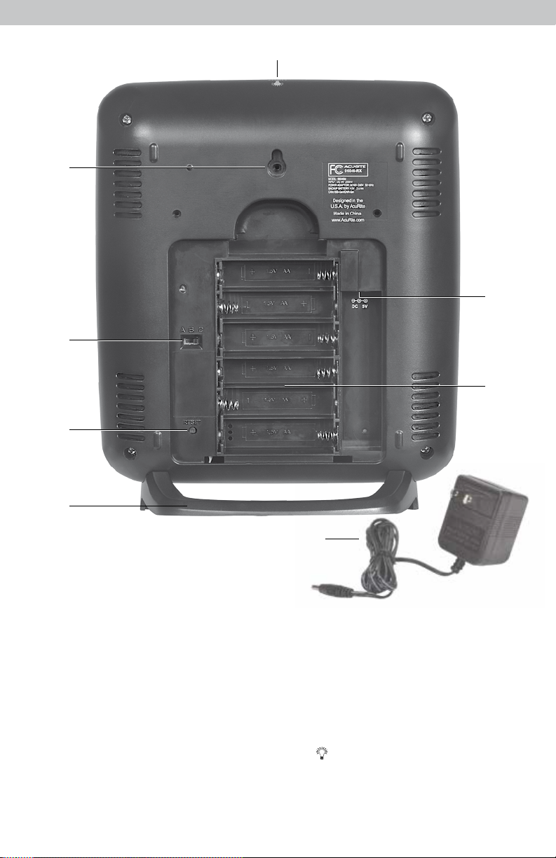
BACK OF DISPLAY
1. Integrated Hang Hole
For easy wall mounting.
2. A-B-C Switch
ID code that must match the
5-in-1 sensor and lightning sensor’s
A-B-C switches to ensure units
synchronize.
3. RESET Button
Press and release for full reset to
factory defaults.
5
4. Removable Tabletop Stand
5. Power Adapter
6. Battery Compartment Cover
(not shown)
7. Plug-in for Power Adapter
8. Button
LIGHT
Dimmer control while using power
adapter. Activates momentary
backlight while on battery power.
8
Page 9
SETUP
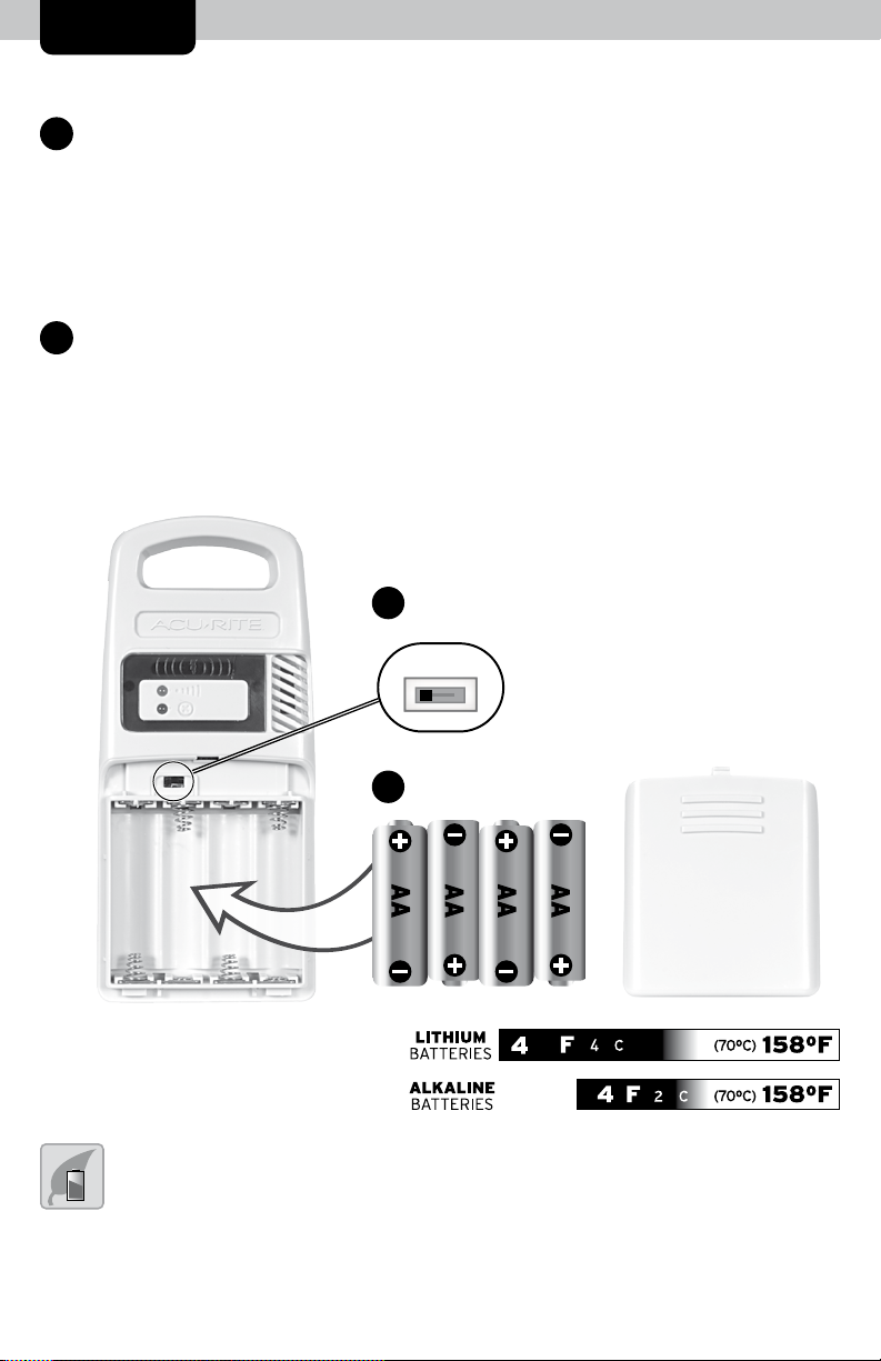
Lightning Sensor Setup
1
Set the A-B-C Switch
Locate the A-B-C switch inside the
•
battery compartment. It can be set
to A, B or C. However, you must
select the same letter choices for the
display, 5-in-1 sensor and lightning
sensor in order for the units to
synchronize.
Install or Replace Batteries
2
AcuRite recommends high quality
•
alkaline or lithium batteries in
the wireless sensor for the best
product performance. Heavy duty
or rechargeable batteries are not
recommended.
The sensor requires lithium batteries
in low temperature conditions. Cold
temperatures can cause alkaline
batteries to function improperly. Use
lithium batteries in the sensor for
temperatures below -4ºF / -20ºC.
1. Slide off the battery compartment
cover.
2. Insert 4 x AA batteries into the
battery compartment, as shown.
Follow the polarity (+/-) diagram
in the battery compartment.
3. Replace the battery cover.
A-B-C Switch
1
Set to match display & 5-in-1 sensor
•
A B C
Install Batteries
2
4 AA batteries
LITHIUM
BATTERIES - • - -
ALKALINE
BATTERIES
PLEASE DISPOSE OF OLD OR DEFECTIVE BATTERIES IN AN ENVIRONMENTALLY SAFE
WAY AND IN ACCORDANCE WITH YOUR LOCAL LAWS AND REGULATIONS.
used for an extended period of time. Follow the polarity (+/-) diagram in the battery compartment. Promptly remove dead batteries from the device. Dispose of used
batteries properly. Only batteries of the same or equivalent type as recommended are to be used. DO NOT incinerate used batteries. DO NOT dispose of batteries in fire,
as batteries may explode or leak. DO NOT mix old and new batteries or types of batteries (alkaline/standard). DO NOT use rechargeable batteries. DO NOT recharge
non-rechargeable batteries. DO NOT short-circuit the supply terminals.
BATTERY SAFETY: Clean the battery contacts and also those of the device prior to battery installation. Remove batteries from equipment that will not be
9
■
tt■••l
•iill\:)
■
•
--'
■
,;,
■~■
•&•11·
■
-
Cti WAH½ (7QOC) 1580f I
(70°C) 158°F I
Page 10

5-in-1 Sensor Setup
Set the A-B-C Switch
1
Locate the A-B-C switch inside the
•
battery compartment. It can be
set to A, B or C. However, you
must select the same letter choices
for the display, 5-in-1 sensor and
lightning sensor in order for the
units to synchronize.
Install or Replace Batteries
2
Batteries MUST be installed for
•
this product to operate. AcuRite
recommends high quality alkaline
or lithium batteries for the best
product performance. Heavy duty
or rechargeable batteries are not
recommended.
The 5-in-1 sensor requires lithium
batteries in low temperature
conditions. Cold temperatures can
cause alkaline batteries to function
improperly. Use lithium batteries in
the 5-in-1 sensor for temperatures
below -4ºF/-20ºC.
1. Slide off the battery
compartment cover.
2. Insert 4 x AA batteries into the
battery compartment, as
shown. Follow the polarity
(+/-) diagram in the battery
compartment.
3. Replace the battery cover.
3
Remove Rain Gauge Stabilizer
Locate and remove the rain gauge
•
stabilizer (plastic tab) taped into
the bottom of the sensor. The rain
gauge will not function until this is
removed.
A B C
A-B-C Switch
1
Set to match
•
display &
lightning sensor
2
Install Batteries
4 AA Batteries
Rain Gauge Stabilizer
3
Remove and discard
•
NOTE: If add-on sensors are being used with the display (see page 17), set them up at this
time. If pairing more than one wireless sensor with the display, the A-B-C channel must differ
between each add-on sensor. The display will automatically begin searching for add-on sensors
during initial setup.
10
Page 11

Display Setup
AcuRite recommends high quality alkaline batteries for the best product
performance. Heavy duty or rechargeable batteries are not recommended.
Set the A-B-C Switch
1
Locate the A-B-C switch inside the
• •
battery compartment. It can be set
to A, B or C. However, you must
select the same letter choices for the
display, 5-in-1 sensor and lightning
sensor in order for the units to
synchronize.
A-B-C Switch
1
Set to match
5-in-1 sensor and
lightning sensor
A B C
Plug Power Adapter into
2
Electrical Outlet
Install or Replace
3
Backup Batteries (optional)
•
Insert 6 x AA alkaline batteries
into the battery compartment,
as shown. Follow the polarity
(+/-) diagram in the battery
compartment.
Install Backup
3
Batteries
(optional)
6 AA Batteries
Plug in Power
2
Adapter
IMPORTANT: Batteries are a backup power source to preserve records in the event of
a power outage. Power adapter is the recommended primary power source to enjoy
the full functionality of this product.
11
Page 12

Set the Time, Date & Units
The display will automatically enter SET MODE after the unit has powered on.
Once in set mode, the preference you are currently setting will blink on the display.
To adjust the currently selected (ashing) item, press and release the “ “ or
V
“ “ buttons (press and HOLD to fast adjust).
To save your adjustments, press and release the “
SET
” button again to adjust
enter
the next preference. The preference set order is as follows:
LANGUAGE (English, French)
COUNTRY (USA, Canada, Australia, Other)
TIME ZONE (EST, CST, MST, PST, AKT, HAT, NST, AST)
AUTO DST CHANGE* (YES, NO)
WEATHER TICKER SPEED (SLOW, MEDIUM, FAST)
CLOCK HOUR
CLOCK MINUTE
CALENDAR MONTH
CALENDAR DATE
CALENDAR YEAR
TEMPERATURE UNITS (ºF or ºC)
WIND SPEED UNITS (mph, kph, knots)
RAINFALL UNITS (in or mm)
PRESSURE UNITS (inHg or hPa)
DISTANCE UNITS (mi or km)
*If you live in an area that observes Daylight Saving Time, DST should be set
to YES, even if it is not currently Daylight Saving Time.
You will automatically exit SET MODE if no buttons are pressed for 15 seconds.
Enter SET MODE at any time by pressing the “
SET
enter
” button.
Display Backlight Settings
This weather station’s color display features three different lighting settings:
High (100%) brightness, Medium (60%) brightness and Low (15%) brightness.
Using battery power alone, the backlight is available momentarily for 10
seconds by pressing the “ ” button.
When the display is powered with the power adapter, the backlight remains
on at 100% brightness. Press the “ ” button once to dim to 60% brightness;
press again to dim to 15%, press a 3rd time to enter “AUTO DIM” mode. “ ”
will appear next to the clock.
NOTE: Pressing and holding the “ ” button for 5 seconds will disable the backlight.
Once any button is pressed, the backlight will return to your selected setting.
AUTO DIM MODE: Automatically adjusts display brightness based on time of day.
LIGHT
LIGHT
LIGHT
6:00 a.m. - 9:00 p.m. = 100% brightness
9:01 p.m. - 5:59 a.m.= 15% brightness
12
LIGHT
Page 13

Placement for Maximum Accuracy
AcuRite sensors are sensitive to surrounding environmental conditions. Proper
placement of the display, 5-in-1 sensor and lightning sensor is critical to the
accuracy and performance of this product.
Display Placement
Place the display in a dry area free of dirt and dust. To ensure
accurate temperature measurement, place out of direct sunlight
and away from heat sources or vents. Display stands upright for
tabletop use or is wall-mountable.
5-in-1 Sensor Placement
The 5-in-1 sensor is designed to remain outdoors all year long.
Choose an open location with no obstructions above or around
the sensor for the most accurate measurements.
Lightning Sensor Placement
The Lightning Sensor is water-resistant and is designed for
general outdoor use, however, to extend its life place the sensor
in an area protected from direct weather elements.
Hang the sensor using the integrated hanger, or by using string
(not included) to hang it from a suitable location, like a well
covered tree branch. The best location is 4 to 8 feet above the
ground with permanent shade and plenty of fresh air to circulate
around the sensor.
Important Placement Guidelines
Display must be within 330 feet (100 meters) of 5-in-1 sensor and lightning sensor.
MAXIMIZE WIRELESS RANGE
Place units away from large metallic items, thick walls, metal surfaces, or other
objects that may limit wireless communication.
PREVENT WIRELESS INTERFERENCE
Place units at least 3 feet (.9 m) away from electronic devices (TV, computer,
microwave, radio, etc.).
LOCATE AWAY FROM HEAT SOURCES
Position sensor away from heaters, air conditioners, chimneys, exhaust vents,
asphalt and concrete (surfaces that radiate heat).
LOCATE AWAY FROM HUMIDITY SOURCES
Avoid installing the sensor near pools, spas, or other bodies of water. Water
sources may impact humidity accuracy.
13
Page 14

LOCATE AWAY FROM SPRINKLER HEADS
DO NOT install the sensor where it will be sprayed by a sprinkler system. This
may force water inside the sensor.
LOCATE AWAY FROM WIND & RAIN OBSTRUCTIONS
DO NOT mount the sensor with obstructions around it.
Consider a location that is a wide open area, with few
structures around to ensure accurate wind measurement.
Visit us online to view installation photos and
video, or learn more about AcuRite technology:
www.AcuRite.com/5in1
View Video
Lightning Sensor Installation Guidelines
False Detection
This sensor features advanced technology to distinguish between lightning
strikes and interference, however in rare cases the sensor may "false detect"
lightning activity due to interference. In these situations, verify there is no
lightning in the area and then relocate the sensor. If the false detections persist,
identify and relocate the source of interference or relocate the sensor.
Interference
The sensor features enhanced interference rejection capabilities to prevent
false lightning detection. When the detector cannot detect lightning due to
interference from nearby equipment, the sensor's interference indicator will ash.
• Electric motors (windshield wiper motor or fan motors in cars, hard drive and
optical drive motors on your PC and AV equipment, well pumps, sump pumps)
• CRT monitors (PC monitors, TV's)
• Fluorescent light xtures (turned off or on)
• Microwave ovens (while in use)
• PC's and mobile phones
WARNING: Take shelter IMMEDIATELY when lightning is present, whether or
not it has been detected by the Lightning Detector. If you are concerned about
lightning strikes, follow all safety precautions to keep yourself and others safe.
DO NOT rely on this Lightning Detector as your only source for warnings
about potentially deadly lightning strikes or other severe weather conditions.
14
Page 15

5-in-1 Sensor Installation Guidelines
INSTALLATION HEIGHT Mount the sensor at a minimum height of 5 feet
(1.5 meters) off the ground, in an open area. Higher is better for wind
measurements - the National Weather Service recommends 33 feet
(10 meters) high!
MOUNTING OPTIONS The included mounting bracket is designed to screw
directly onto wooden posts or surfaces that are 2”x 4” or larger. The sensor
can also be mounted directly to 3/4” steel pipe (available at hardware stores
and home centers).
SOLAR CELL INSTALLATION Install the sensor
with the solar cell facing SOUTH. This ensures
the cell receives as much sun as possible and
orients wind direction.
NO OBSTRUCTIONS
ABOVE OR AROUND
SOUTH
5-in-1 Sensor Installation
1. Fasten mounting base (included) to a post
or pole (not included) using the 4 longer
screws included in the hardware bag.
2. Insert the mounting base into the hole on
the bottom of the sensor.
3. Make sure the arrows on the top of the
sensor are pointed in the proper direction
and the bubble level is centered. The solar
cell should be facing south to properly
orient the wind direction.
(1.5 meters)
4. Fasten the sensor into the mounting base
using the 2 shorter screws included in the
hardware bag.
The 5-in-1 sensor is now ready to use.
Basic Setup is Complete
The 5-in-1 sensor will now synchronize with the display. It may take a few
minutes for synchronization to complete. If both or one of the units appear to
be functioning improperly, please refer to the troubleshooting section.
15
Page 16

OPERATION
Using the Professional Weather Center
Learning Mode
Self-Calibrating Forecasting use a unique algorithm to analyze changes in pressure over
a time period (called Learning Mode) to determine your altitude. After 14 days, the
icon disappears from the display screen. At this point, the self-calibrated pressure is
tuned in to your location and the unit is ready for superior weather prediction.
Weather Forecast
AcuRite’s patented Self-Calibrating Forecasting provides your personal forecast of weather
conditions for the next 12 to 24 hours by collecting data from the sensor in your backyard.
It generates a forecast with pinpoint accuracy - personalized for your exact location.
STORMY
& WINDY
(flashing=stormy)
SNOW
LIKELY
SNOW / RAIN
MIX LIKELY
RAIN
LIKELY
CLOUDY
View the complete list of icons at www.AcuRite.com/acurite-icons
Weather Select
Weather Select displays data including wind chill, dew point and heat index based
on current outdoor conditions. To manually change the Weather Select reading
being displayed:
1. Press and release the “select” button until “WEATHER SELECT” is shown on the
Weather Ticker.
2. Press and release the “options” button.
3. Press and release the “
the display.
4. Press and release the “
After 5 seconds of inactivity, you will exit set mode.
” or “ ” buttons until the desired reading is shown on
SET
” button to save your selection.
enter
Wind Speed
This weather center displays the current, average and peak wind speeds. By
default, average wind speed is calculated in 2-minute intervals. To adjust the time
interval for average wind speed calculations:
1. Press and release the “select” button until “WIND SPEED AVERAGE” is shown
on the Weather Ticker.
2. Press and release the “options” button.
3. Press and release the “
4. Press and release the “
on the display.
5. Press and release the “
After 5 seconds of inactivity, you will exit set mode.
SET
” button.
enter
V
” or “ ” buttons until the desired interval is shown
SET
” button to save your selection.
enter
16
Page 17

Barometric Pressure
Subtle variations in barometric pressure greatly affect the weather. This weather
center displays the current pressure with an arrow icon to indicate the direction the
pressure is trending (FALLING, STEADY, or RISING).
Lightning Detection
The lightning sensor detects cloud-to-cloud, cloud-to-ground and intra-cloud
lightning. When lightning is detected, the sensor will beep and the strike indicator
will ash for each of the rst 10 strikes. After 10 strikes, the sensor will enter silent
mode but will continue to ash. The sensor will stay in silent mode for 2 hours after
the last lightning detection.
The display will automatically show the most recent lightning event (TODAY, WEEK,
MONTH). The
keeps a running count of lightning strikes detected. The display shows an estimate
of the distance to the front of today’s lightning-producing storm.
icon appears on the display when lightning is detected and
Expand the System
The display features built-in sensors for measuring temperature and humidity
at its location. The display can be expanded to track additional areas by using
compatible Temperature & Humidity Sensors (optional; sold separately). Add up
to 3 indoor/outdoor sensors to observe conditions in additional locations within
330 ft (100 m).
Compatible Sensors are available at: www.AcuRite.com
Compatible Sensors Perfect for:
E
Temperature & Humidity Sensor
Model 06002
Temperature & Humidity Sensor
Model 06044
• Indoor and outdoor applications
• Integrated digital display for conditions
at a glance
• Measures temperature and humidity
• For indoor applications
View Indoor/Add-On Sensor Readings
The weather station displays the current indoor temperature and humidity readings,
by default.
If the weather station is being used with additional sensors (see Expand the
System), toggle between indoor readings and each sensor’s readings by pressing
and releasing the “
In auto-cycle mode, the display will automatically cycle through indoor and each
sensor’s data. Auto-cycle mode can be activated by pressing and releasing the
“
“ or “ “ buttons until the “ “ indicator appears.
“ or “ “ buttons.
V
17
Page 18

The Sensor Indicator is used to determine which add-on sensor readings you
are viewing. For example, if the Sensor Indicator is displaying “A”, the readings
are being transmitted from the sensor with the A-B-C switch set to “A”.
Rainfall Tracking
This weather station features enhanced tracking of historical rainfall data.
Rain accumulation data is displayed for the current day, yesterday, or week
(most recent rainfall total). Press the “ ” button to review historical rainfall
records.
Records are shown in the following order:
CURRENT YEAR TOTAL (default)
PREVIOUS MONTHLY TOTALS WITH RAIN (up to 12 months prior)
CURRENT YEAR TOTAL
PREVIOUS YEAR TOTAL
ALL-TIME TOTAL
Rainfall Data
in.
"
Rainfall History
135 today
•
TODAY
Displays rainfall
recorded TODAY
since 12:00am,
if applicable.
35 today
in.
"
•
Y0.27 2018
CURRENT YEAR TOTAL RAINFALL ALL-TIME TOTAL RAINFALL
TOTAL RAINFALL FOR MONTH SHOWN
(default)
in .
l35 yesterday r.
"
YESTERDAY
If there hasn’t been any
rainfall this week, the
current month’s rainfall is
displayed.
35 today
in.
"
•
B.35 OCT 96.BY ALL
If there hasn’t been any
rainfall today, the current
week’s rainfall (Sunday to
Saturday) is displayed, if
in.
"
1.35 week
WEEK
applicable.
35 today
•
Weather Ticker
The Weather Ticker automatically ashes your real-time weather information
and alerts as text in the lower part of the display screen.
The possible WEATHER TICKER messages are as follows:
HEAT INDEX-XX
WINDCHILL-XX
DEW POINT-XX
™
18
Page 19

IT FEELS LIKE XX OUTSIDE
TODAY’S HIGH HUMIDITY...OUTDOOR XX/INDOOR XX
TODAY’S LOW HUMIDITY...OUTDOOR XX/INDOOR XX
TODAY’S HIGH TEMP...OUTDOOR XXX/INDOOR XXX
TODAY’S LOW TEMP...OUTDOOR XXX/INDOOR XXX
7 DAY HIGH TEMP. XX–MM/DD
7 DAY LOW TEMP. XX–MM/DD
30 DAY HIGH TEMP. XX–MM/DD
30 DAY LOW TEMP. XX–MM/DD
ALL TIME HIGH TEMP. XXX…RECORDED MM/DD/YY
ALL TIME LOW TEMP. XXX…RECORDED MM/DD/YY
24 HOUR TEMP. CHANGE +XX
ALL TIME HIGH WIND XX MPH…RECORDED MM/DD/YY
7 DAY AVERAGE WIND XX MPH
TODAY’S AVERAGE WIND XX MPH
MOON- NEW
MOON- WAXING CRESCENT
MOON- FIRST QUARTER
MOON-WAXING GIBBOUS
MOON- FULL
MOON- WANING GIBBOUS
MOON- LAST QUARTER
MOON- WANING CRESCENT
INDOOR HUMIDITY OK
INDOOR HUMIDITY HIGH
INDOOR HUMIDITY LOW
NEW LOW TEMP. RECORD XX
NEW HIGH TEMP. RECORD XX
NEW WIND RECORD TODAY XX
CURRENT RAINFALL RATE X.XX /HR.
RAIN EVENT STARTED XX HRS. AGO
5-IN-1 SENSOR BATTERIES LOW
DISPLAY BATTERIES LOW
5-IN-1 SENSOR SIGNAL LOST…CHECK BATTERIES AND PLACEMENT
CAUTION– HEAT INDEX IS XXX
CAUTION– WIND CHILL IS XXX
LIGHTNING DETECTED...XX MILES AWAY...STRIKES CLOSER
LIGHTNING DETECTED...XX MILES AWAY...STRIKES FARTHER AWAY
LIGHTNING STRIKES...LAST 48 HOURS - XXXX
LIGHTNING STRIKES...LAST MONTH - XXXX
LIGHTNING STRIKES...THIS YEAR - XXXX
LIGHTNING STRIKES...LAST YEAR - XXXX
LIGHTNING STRIKES...ALL TIME - XXXX
MOST LIGHTNING...IN ONE DAY - XXXX...MM/DD/YY
CAN’T DETECT LIGHTNING...RELOCATE SENSOR
LIGHTNING SENSOR...BATTERIES LOW
LIGHTNING SENSOR...SIGNAL LOST...CHECK BATTERIES... AND PLACEMENT
19
Page 20

High and Low Records
Today’s high and low records are displayed for outdoor temperature and
humidity. Today’s records automatically clear at 12:00am midnight every day.
Historical records (daily, weekly, monthly) can also be viewed by accessing the
records menu. Records include:
OUTDOOR TEMPERATURE
OUTDOOR HUMIDITY
BAROMETRIC PRESSURE
WIND SPEED
RAINFALL
INDOOR TEMPERATURE
INDOOR HUMIDITY
LIGHTNING STRIKES
View Records
1. Press and release the “select” button until the reading for which you wish to
view is shown on the Weather Ticker screen.
2. Press and release the “records” button to enter RECORDS MODE.
3. Press and release the “ ” or “ ” buttons to cycle through available record
values for that reading.
4. Repeat steps 1-3, as needed.
NOTE: To clear a record, press and release the “clear” button while viewing the
record you wish to clear. Dashes display to conrm you have cleared the record.
V
Programmable Weather Alarms
Each selectable weather category features an alarm option. When an alarm
sounds, the display emits audible beeping and ashes the affected category, its
alarm settings, and any other relevant data.
Alarms can be customized to alert you when your programmed value is
reached. Alarms include:
OUTDOOR TEMPERATURE
OUTDOOR HUMIDITY
BAROMETRIC PRESSURE
WIND SPEED
WEATHER SELECT
RAINFALL
INDOOR TEMPERATURE
INDOOR HUMIDITY
LIGHTNING STRIKES (ON/OFF only; ON by default)
20
Page 21

Setup an Alarm
Press and release the “select” button until the reading for which you wish to set
an alarm for is shown on the Weather Ticker screen.
1. Press and release the “alarms” button to enter ALARM SET MODE.
2. Press and release the “
3. Press and release the “ ” or “ ” buttons until “ALARM ON” is ashing
SET
enter
” button.
V
on the Weather Ticker screen.
4. Press and release the “
SET
” button. The current LOW alarm value will be
enter
shown on the display.
5. Press and release the “ ” or “ ” buttons to adjust the alarm’s LOW value.
6. Press and release the “
enter
V
SET
” button. The current HIGH alarm value will be
shown on the display.
7. Press and release the “ ” or “ ” buttons to adjust the alarm’s HIGH value.
8. Press and release the “
9. Repeat steps 1-8, as needed.
SET
enter
V
” button.
Disable an Alarm
Press and release the “select” button until the reading for which you wish to set
an alarm is shown on the Weather Ticker screen.
1. Press and release the “
2. Press and release the “
3. Press and release the “ ” or “ ” buttons until “ALARM OFF” is ashing
alarms
” button to enter ALARM SET MODE.
SET
” button.
enter
V
on the Weather Ticker screen.
4. Press and release the “
5. Repeat steps 1-4, as needed.
NOTE: To disable ALL alarms at once, press and HOLD the “
SET
enter
” button.
alarms
” button for
15 seconds.
21
Page 22

Troubleshooting
Problem Possible Solution
No 5-in-1 sensor
or lightning sensor
reception
no bars
Tull
• Relocate the display and/or the sensor. The units must be
within 330 ft (100 m) of each other.
• Make sure all units are placed at least 3 feet (.9 m)
away from electronics that may interfere with the wireless
communication (such as TVs, microwaves, computers, etc).
• Use standard alkaline batteries (or lithium batteries in
sensor when temperature is below -20ºC/-4ºF). Do not use
heavy duty or rechargeable batteries.
a few minutes for display and sensors to synchronize after
batteries are replaced.
• Synchronize the units:
1. Bring both sensors and display indoors and remove
power adapter/batteries from all.
2. Reinstall batteries in outdoor sensors.
3. Reinstall power adapter/batteries in display.
4. Let the units sit within a couple feet of each other for a
few minutes to gain a strong connection.
NOTE: It may take
Outdoor
temperature
is ashing or
showing dashes
Inaccurate forecast
Inaccurate
temperature or
humidity
Flashing of the outdoor temperature may be an indication of
wireless interference.
• Make sure the A-B-C switch in the battery compartments the
display and both sensors are switched to the same letter.
You may choose A, B or C; but units must match to sync up.
Sometimes changing to a different channel can help.
• Weather Forecast icon predicts conditions for the next
12 to 24 hours, not current conditions.
• Has Learning Mode icon disappeared from the display?
Learning Mode must complete before forecast and
pressure will be accurate.
• Allow unit to run continuously for 33 days. Battery removal
or resetting the display will restart Learning Mode. After 14
days, forecast should be fairly accurate, however Learning
Mode calibrates for a total of 33 days.
• Make sure both the display and 5-in-1 sensor are placed
away from any heat sources or vents
(see page 13).
• Make sure both units are positioned away from moisture
sources (see page 13).
• Make sure 5-in-1 sensor is mounted at least 1.5 m (5 ft)
off of the ground.
• Calibrate indoor and outdoor temperature and humidity
(see page 24).
22
Page 23

Troubleshooting
Problem Possible Solution
No rainfall
Inaccurate wind
readings
Display screen
not working
• Check to ensure the rain gauge stabilizer (plastic tab) has
been removed from the bottom of the sensor (see page 10).
• Clear debris, such as leaves, out of the rain collector
funnel and debris screen.
• Calibrate the Rain Gauge (see page 25).
• What is wind reading being compared to? Pro weather
stations are typically mounted at 30 ft (9 m) high or more.
Make sure to compare data using a sensor positioned at
the same mounting height.
• Check location of the sensor. Ensure it’s mounted a
minimum of 5 ft (1.5 m) in the air with no obstructions
around it (within several feet).
• Ensure wind cups are spinning freely. If they hesitate or stop
try lubricating with graphite powder or spray lubricant.
• Check that the power adapter is plugged into the
display and an electrical outlet.
• Reset the display by pressing and releasing the RESET
button, located in the battery compartment of the display.
Time and date will need to be entered after a reset.
If the display is being used with add-on Temperature & Humidity
Add-on Sensor
not recognized
Interference
Indicator is ashing
Sensors (models 06002 or 06044), the A-B-C channels must differ
between each add-on sensor.
1. Bring the display and wireless sensors together and
position them side-by-side.
2. Unplug cord & remove the batteries from the display.
3. Verify that each sensor has a different A-B-C channel selected.
• Model 06002 - Locate the A-B-C switch inside the
battery compartment to adjust channel setting.
• Model 06044 - Locate the A-B-C button on the back of the
sensor to adjust channel setting (indicated on sensor display).
4. Re-install sensor batteries (if applicable).
5. Plug in & re-install display batteries.
NOTE: It may take a few minutes for the display and
sensor(s) to synchronized after batteries are replaced.
• Relocate the lightning sensor.
• Make sure the lightning sensor is placed at least
3 feet (.9 m) away from electronics that may cause
interference (see page 14).
If your AcuRite product does not operate properly after trying
the troubleshooting steps, visit www.AcuRite.com or call
(877) 221-1252 for assistance.
23
Page 24

Care & Maintenance
Display Care
Clean with a soft, damp cloth. Do not use caustic cleaners or abrasives. Keep away
from dust, dirt and moisture. Clean ventilation ports regularly with a gentle puff of air.
5-in-1 Sensor Care
Clean the Sensor
Clean with a soft damp cloth. Do not use caustic cleaners or abrasives that
will mar the polished surfaces of the rain collection funnel or the solar cell.
Scratches will result in decreased performance and reliability.
Insect Prevention
Insects may cause obstructions and interrupt data by nesting in or on the 5-in-1
sensor. To limit this problem, spray sensor with a household insect repellent.
Consult the insect repellent instructions prior to use.
Snow & Freezing Weather
The 5-in-1 sensor will not be damaged by freezing conditions. NOTE: If the rain
collector cup lls with snow and then melts, it will register as rain on the display.
Clean the Rain Collector Cup
Remove and empty rain collector debris lter. The debris lter is located in the
rain collector funnel. Remove from the top by gently squeezing and pulling out.
Clean the Wind Vane & Anemometer
Remove foreign matter from the outside of the sensor for free movement of the
wind vane and anemometer. If needed, use a small amount of spray lubricant,
clear silicone or graphite powder on the anemometer for improved movement.
Lightning Sensor Care
Clean with a soft, damp cloth. Do not use caustic cleaners or abrasives.
Calibration
The indoor and outdoor temperature and humidity readings, and barometric
pressure* can be calibrated on the display to improve accuracy. Calibration
can improve accuracy when sensor placement or environmental factors impact
the data accuracy.
1. To access calibration mode, press and release the “select” button until the
reading you wish to calibrate is shown on the Weather Ticker.
2. Press and release the “options” button.
3. If necessary, press and release the “ ” or “ ” button until “CALIBRATION”
is shown on the Weather Ticker.
4. Press and release the “
on the display.
5. Press and release the “ “ or “ “ button to calibrate the data value higher
or lower from the actual reading.
6. To save your adjustments, press and release the “
icon will remain illuminated next to calibrated values.
7. Repeat steps 1-6, as needed.
SET
” button. The currently selected item will ash
enter
24
V
SET
” button. The “
enter
”
Page 25

*Barometric pressure must be set to MANUAL mode to calibrate. To change
from AUTO to MANUAL pressure mode and vice versa, press and release the
“select” button until BAROMETER is shown on the Weather Ticker. Press and
release the “options” button and then cycle through the options using the “
“ “ button. Press and release “
V
SET
” button once the mode you desire appears
enter
“ or
on the Weather Ticker. The “ ” icon will appear next to the barometric
pressure to indicate that MANUAL mode has been activated.
After 5-10 seconds of inactivity, the display will save the adjustments and exit
calibration mode. NOTE: Calibrations will be erased if the display is reset or if
batteries are removed and the power adapter is unplugged.
Calibrate the Rain Gauge
The rain gauge on the 5-in-1 sensor can be calibrated to improve accuracy.
Items Needed: 5-in-1 sensor, display, plastic cup, pin, screw driver
1. First, ensure 5-in-1 sensor is perfectly level using built-in bubble level.
2. Place display close so you can monitor it during calibration.
3. Make a pin hole in the bottom of a plastic cup. Hold the cup over the rain
gauge and ll it with exactly 1 cup (8oz) of water, allowing the water to drip
into the rain gauge. You should hear the internal buckets tip and see water
drain through the rain gauge.
4. A few seconds after each bucket tip, the display displays rainfall in
approximately 0.01” (.25 mm) or more increments.
5. The cup of water should take more than 20 minutes to empty; a quicker
period will result in inaccurate calibration. Try to simulate a normal steady
rainfall. When cup is empty of water, display should register 1.06” (27 mm).
Tips
• There should be nearly an equal number of water drops (about 25 water
drops) between bucket tips. If not, adjust the calibration screws on the
bottom of the 5-in-1 sensor until an equal number of water drops are tipping
the buckets. Then, restart the calibration procedure.
• If you don’t hear the buckets tipping and see water dripping alternately out
of each drain, there may be an issue with the rain gauge or it’s adjustment.
See Troubleshooting on page 22.
Adjustment
If the rain gauge doesn’t register close to 1.06” (27 mm), make an EQUAL
adjustment to the two calibration screws on the bottom of the 5-in-1 sensor.
Turning screws clockwise increases rainfall; counter clockwise decreases rainfall.
• To adjust the rainfall reading by 2% turn both screws 1/8 of a turn.
• To adjust the rainfall reading by 4% turn both screws 1/4 of a turn.
• To adjust the rainfall reading by 8% turn both screws 1/2 of a turn.
Watch the video at www.acurite.com/5in1
25
Page 26

Specications
TEMPERATURE RANGE
HUMIDITY RANGE
LIGHTNING DETECTION
RANGE
WIND SPEED
WIND DIRECTION
INDICATORS
RAINFALL MEASUREMENT
WIRELESS RANGE
OPERATING FREQUENCY
POWER
DATA REPORTING
Outdoor: -40ºF to 158ºF; -40ºC to 70ºC
Indoor: 32ºF to 122ºF; 0ºC to 50ºC
Outdoor: 1% to 99%
Indoor: 1% to 99%
1 - 25 miles / 1.6 - 40km
0 to 99 mph; 0 to 159 km/h
16 points
0.01 inches (0.25 mm) and up
330ft / 100m depending on home construction materials
433 MHz
Display: 5V, 250mA adapter
6 x AA alkaline batteries (optional)
5-in-1 Sensor: 4 x AA alkaline or lithium batteries
Lightning Sensor: 4 x AA alkaline or lithium batteries
Display: Indoor temperature & humidity: 60 second updates
5-in-1 Sensor: Wind Speed: 18 second updates;
Direction: 36 seconds; Outdoor temperature & humidity:
36 second updates
Lightning Sensor: 24 second updates during normal
conditions; 8 seconds once lightning detected
FCC Information
This device complies with part 15 of FCC rules. Operation is subject to the following two conditions:
1- This device may NOT cause harmful interference, and
2- This device must accept any interference received, including interference that may cause undesired operation.
WARNING: Changes or modications to this unit not expressly approved by the party responsible for compliance could void the
user’s authority to operate the equipment.
NOTE: This equipment has been tested and found to comply with the limits for a Class B digital device, pursuant to Part 15 of the
FCC rules. These limits are designed to provide reasonable protection against harmful interference in a residential installation. This
equipment generates, uses and can radiate radio frequency energy and, if not installed and used in accordance with the instructions,
may cause harmful interference to radio communications. However, there is no guarantee that interference will not occur in a
particular installation. If this equipment does cause harmful interference to radio or television reception, which can be determined by
turning the equipment off and on, the user is encouraged to try to correct the interference by one or more of the following measures:
• Reorient or relocate the receiving antenna.
• Increase the separation between the equipment and the receiver.
• Connect the equipment into an outlet on a circuit different from that to which the receiver is connected.
• Consult the dealer or an experienced radio/TV technician for help.
NOTE: The manufacturer is not responsible for any radio or TV interference caused by unauthorized modications to this equipment.
Such modications could void the user authority to operate the equipment.
This device complies with Industry Canada licence-exempt RSS standard(s).
Operation is subject to the following two conditions:
(1) This device may not cause interference, and
(2) This device must accept any interference received, including interference that may cause undesired operation of the device.
26
Page 27

27
Limited 1-Year Warranty
We expressly disclaim all liability for special, consequential,
Canada, please consult the policies applicable to the country in
PURPOSE.
State of Wisconsin.
Wisconsin; and purchaser consents to jurisdiction within the
federal or State courts having jurisdiction in Walworth County,
dispute relating to this Policy shall be brought exclusively in the
laws of the United States and the State of Wisconsin. Any
This Return, Refund, and Warranty Policy is governed by the
Governing Law
resale sites such as eBay or Craigslist.
refund, or warranty services if you buy products used or from
of our products. We cannot and do not offer any return,
Additionally, this Policy applies only to the original purchaser
which you made your purchase.
purchases made in a country other than the United States or
purchases made in the United States and Canada. For
This Return, Refund, and Warranty Policy applies only to
Applicability of Policy
original purchase price paid for the product.
products, your purchase or your use thereof, exceed the
In no case shall our liability for any claim relating to our
writing and signed by a duly authorized agent of ours.
to modify or waive the terms of this warranty unless done in
Furthermore, no person, rm or corporation is authorized
or liability in connection with the sale of our products.
or corporation is authorized to bind us to any other obligation
consequences arising from their use or misuse. No person, rm
any of our products, the purchaser assumes all liability for the
our products to the extent permitted by law. By acceptance of
We further disclaim liability from personal injury relating to
so the above limitation or exclusion may not apply to you.
exclusion or limitation of incidental or consequential damages,
from any breach of this warranty. Some states do not allow the
or incidental damages, whether arising in tort or by contract
AND THE IMPLIED WARRANTY OF FITNESS FOR A PARTICULAR
LIMITATION THE IMPLIED WARRANTY OF MERCHANTABILITY
ARE HEREBY EXPRESSLY DISCLAIMED, INCLUDING WITHOUT
OTHER THAN THE EXPRESS WARRANTY SET FORTH HEREIN
WARRANTIES, EXPRESS OR IMPLIED. ALL OTHER WARRANTIES
FOR THE PRODUCTS AND IS EXPRESSLY IN LIEU OF ALL OTHER
THE ABOVE-DESCRIBED WARRANTY IS THE SOLE WARRANTY
the amount of the original purchase price.
or replacement is not feasible, we may, at our option, refund
replacement of the defective item(s). If we determine that repair
Remedy for breach of this warranty is limited to repair or
than our authorized representatives.
abused, improperly installed, or repaired or altered by others
been damaged (including by acts of nature), tampered,
wear and tear not affecting the functionality of the product,
will give no credit for products which have received normal
costs and charges. This warranty will not be breached, and we
We hereby disclaim all responsibility for such transportation
charges for returned goods shall be paid for by the purchaser.
option, be repaired or replaced by us. Transportation costs and
from date of sale will, upon examination by us, and at our sole
to breach the warranty contained herein within ONE YEAR
Any product which, under normal use and service, is proven
period of one year from the date of purchase.
properly installed and operated, will be free of defects for a
warranty are of good material and workmanship and, when
We warrant that all products we manufacture under this
provides the benets and services set forth herein.
forth herein. For purchases of Chaney products, Chaney
products, AcuRite provides the benets and services set
Instrument Company. For purchases of AcuRite
AcuRite is a wholly owned subsidiary of Chaney
www.AcuRit e.com
PRODUCT REGIS TRATION
TO RECEIVE WARRANT Y SERVICE
PRODUCT MUS T BE REGIS TERED
Regist er online t o receive 1 year war ranty pro t ection
IMPORTANT
(877) 221-1252
► Replacement Parts ► Submit Feedback & Ideas
► Instruction Manuals ► Support User Forum
► Installation Videos ► Register your Product
Visit us at www.AcuRite.com
Q)
product available and contact us in any of the following ways:
class service. For assistance, please have the model number of this
AcuRite customer support is committed to providing you with best-in-
Customer Support
Page 28

ACU
►
RITE®
Weather Temperature Weather Kitchen
Stations & Humidity Alert Radio Thermometers
designed to provide you with information you can depend on to
& Timers
It’s More than Accurate, it’s
AcuRite offers an extensive assortment of precision instruments,
Plan your day with condence
ACU
►
.
™
Clocks
RITE.
www.AcuRite.com
©Chaney Instrument Co. All rights reserved. AcuRite is a registered trademark of
the Chaney Instrument Co., Lake Geneva, WI 53147. All other trademarks and copy-
Printed in China
06046M INST 071516 Visit www.AcuRite.com/patents for details.
rights are the property of their respective owners. AcuRite uses patented technology.
 Loading...