

Page 1
1995-1998 2.5TL/3.2TL Body Repair Manual
INTRODUCTION
How to Use This Manual
Body Repair
Preparation of
Work
1
This manual covers the repairs of 1995-1998 Acura 2.5TL/3.2TL automobiles which have been involved
in accidents, and it describes the work related to the replacement of damaged body parts.
Please read through these instructions and familiarize yourself with them before actually using this
manual.
NOTE: Refer to the 1995-1998 Acura 2.5TL Service Manual (P/N 61SW504) and 1996-1998 Acura
3.2TL Service Manual Supplement (P/N 61SW505) for specifications, wire harness locations, safety
stand support points, etc.
Special Information
WARNING
Indicates a strong possibility of severe personal injury or death if instructions are not followed.
CAUTION
Indicates a possibility of personal injury or equipment damage if instructions are not followed.
NOTE: Gives helpful information.
CAUTION
Detailed descriptions of standard workshop procedures, safety principles and service operations are
not included. Please note that this manual does contain warnings and cautions against some specific
service methods which could cause PERSONAL INJURY, damage a vehicle, or make it unsafe.
Please understand that these warnings cannot cover all conceivable ways in which service, whether
or not recommended by Honda, might be done or of the possible hazardous consequences of each
conceivable way, nor could Honda investigate all such ways. Anyone using service procedures or
tools, whether or not recommended by Honda, must satisfy himself thoroughly that neither personal
safety or vehicle safety will be jeopardized.
Welding Methods/
Repair Tools
2
General
Information
3
Replacement
4
Cross Section
of Body and
5
Sealants
Body
Dimensional
6
Drawings
Rust-preventive
Treatments
7
All information contained in this manual is based on the latest product information available at the time of
printing. We reserve the right to make changes at any time without notice. No part of this publication may be
reproduced, stored in retrieval system, or transmitted, in any form by any means, electronic, mechanical,
photocopying, recording, or otherwise, without the prior written permission of the publisher. This includes
text, figures and tables.
HONDA MOTOR CO., LTD.
Service Publication Office
First Edition 5/95 158 pages
All Rights Reserved
Paint Repair
Body Paint
Repair
8
Resin Parts
Paint Repair
9
(Exterior)
Service Precautions
General Safety
Precautions
Page 2
Preparation of Work
Main Menu
Table of Contents
Description
• Most monocoque bodies are composed as a single unit by welding together pressed parts made of steel plates which come in
a variety of different shapes and sizes. Each part is responsible for displaying a certain strength and durability in order that it
may play its role in meeting the functions of the body as a whole.
Damage to the exterior of the body can be inspected visually, but where there has been an external impact, it is necessary to inspect
the extent of the damage. In some cases, the deformation has spread beyond the actual areas which were in the collision and so
this has to be inspected closely.
Page 3

Checkpoints
Main Menu
Table of Contents
• Accurate Inspection of Damaged Parts (Visual)
Seat Belts
Replace the seat belts if:
1. The belt material is cut, punctured, burned or in any way damaged.
2. The buckle or retractor does not work properly.
3. They were being worn at the time of a collision (check for damage at the seat belt anchor points).
4. Their condition is questionable.
Front Section:
1. Is there any bending, splitting, denting or other damage to the suspension and its related parts?
2. Is there any deformation of the front bulkhead or radiator core? Have any of the connected sections come apart?
3. Are there any creases or distortion in the front wheelhouse or side frame? Have any of the connected sections come apart?
4. Is there any bending or twisting of the whole front area?
5. Is there any deformation like creases, bulges, or dents in the front pillar, dashboard, floor, etc.?
6. Is there any vertical twisting or misaligned clearance in the door?
7. Is the windshield seal broken?
8. Is there any deformation in the vicinity of the top part of the roof panel's center pillar?
9. Is there any damage inside the automobile (is there any twisting of the dashboard, or anything irregular with the clearances
or sheet-mounting parts)?
10. Is there any damage to the steering wheel? Is there any deformation in the column and the column-mounted parts?
11. Is there any oil or water leakage and damage to the engine, transmission or brakes?
12. Is there any irregular noise in the gear changing operation, engine and transmission rotation?
13. Are there any traces of contact between the engine block and the dashboard lower panel?
14. Is there any damage to brake or fuel lines, or wire harnesses?
Rear Section:
1. Is there any twisting, bulging or denting of the rear floor and rear bolsters? Have any of the connected sections come apart?
2. Is there any irregular bulging or denting in the rear fender?
3. Is there any distortion in the rear inner panel? Is there any bending and denting in the vicinity of the rear pillar?
4. Is there any distortion or creasing is the rear wheelhouse and arch sections? Have any of the connected sections come apart?
5. Is there anything irregular in the rear glass and quarter glass seal clearance?
6. Is there any twisting or misalignment of the clearance of the trunk lid or tailgate opening section?
7. Is there any bending, splitting, denting or other damage to the suspension and its related parts?
8. Is there any deformation of the rear floor, rear floor cross member and damper base? Have any of the connected sections
come apart?
Page 4
Preparation of Work
Main Menu
Table of Contents
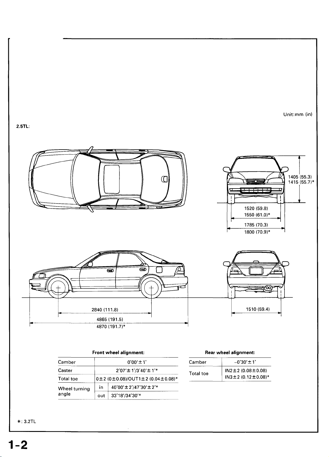
Correction of the Damaged Area
Set the frame corrector on the car body.
The side sill is flangeless to allow reshaping by pulling it out.
Use the horizontal pinch welds for anchoring the car.
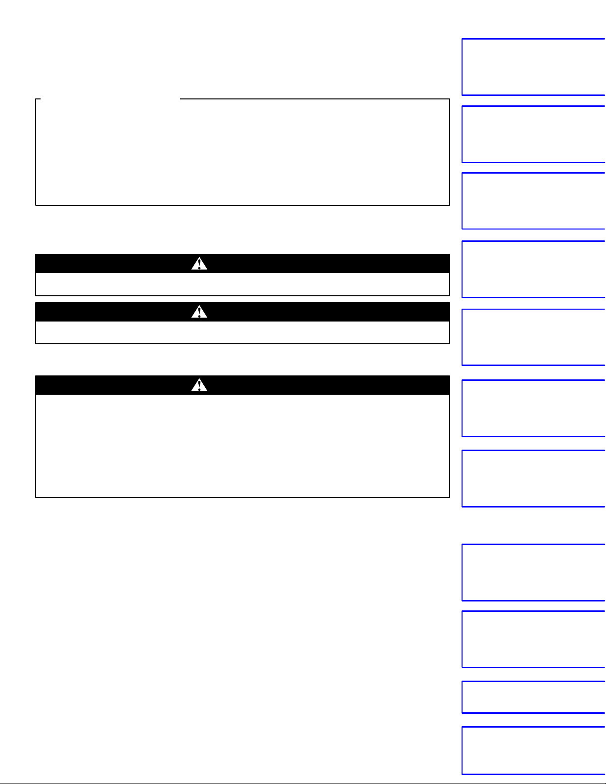
Underbody Clamp Specifications:
UNDERBODY CLAMPS
Page 5

1. Apply load to the damaged section and pull it out until
Main Menu
Table of Contents
the section is almost restored to the original shape.
8. Weld the replacement parts.
Welding methods (see section 2).
2. Check that the parts of the body they cover have been
more or less restored to their original shapes.
NOTE: Check the original position using the body
dimensional drawings (see section 6) and the positioning jigs (see page 1-7).
3. Remove the parts that require replacement.
4. Decide whether to replace all the affected parts or
whether to cut the weld joint parts and replace them.
5. Cut off and separate the damaged parts.
NOTE: When cutting the parts off, take special care
that you do not damage adjacent parts on the automo-
bile.
Setting Condition of Replacement Parts Joint Sections:
• Make sure that you can perform straightening work
after welding.
• Make sure that the locations are not susceptible to
distortion caused by other parts.
• Make sure that there are few removable parts and
that the location allows safe welding.
• Make sure that the joints are short, and that paint
repair can be performed easily.
• Make sure the locations are such that the joints can
be finished in a way that does not affect the outward
appearance.
• Make sure that the locations do not hinder the
removing and attaching of parts.
NOTE: Bear in mind all of these conditions, and after
determining the joint locations, cut the joints for an
overlap of 20~30 mm (0.8~1.2 in).
NOTE: Use of the positioning jig is recommended.
CAUTION: Protect body parts with the heat-resistant
protective cover to prevent damage, when welding.
The paint film, which is designed to prevent corrosion
caused by moisture, is destroyed around the edges of the
locations which have been repaired by welding.
Therefore, in such places and especially in those areas
which are not visible, apply another coat of the paint,
referring to the anti-corrosion painting manual. This
operation is designed to maintain durability and quality
(see section 7).
6. Mold the related parts.
7. Set and tack weld the replacement parts.
NOTE: Temporarily mount the related parts and check
the clearance and level differences.
Page 6
Preparation of Work
Main Menu
Table of Contents
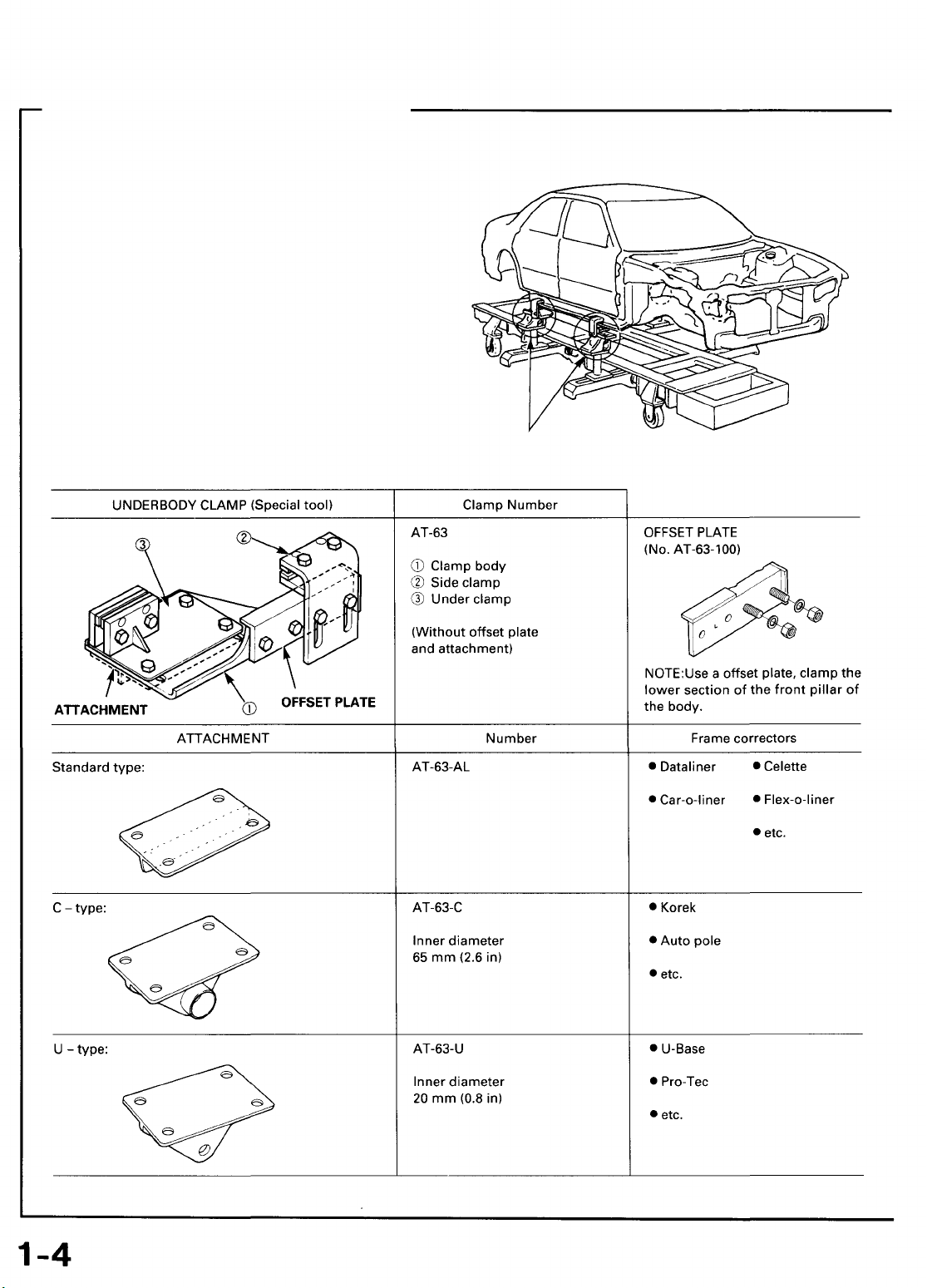
Measurement (Excluding small damage)
Whenever possible, make judgements and conclusions based on measurement. Measure the wheel alignment (see page 1-2) so as to
prevent any future trouble like unsymmetrical wear of the tires or catching of the steering wheel.
If there are any deviations, use a tram tracking gauge and measure parts of the body.
POINTER A
If there is any twisting to the body, measure using a frame centering gauge.
When measuring body dimensions, use a universal tram gauge.
Page 7
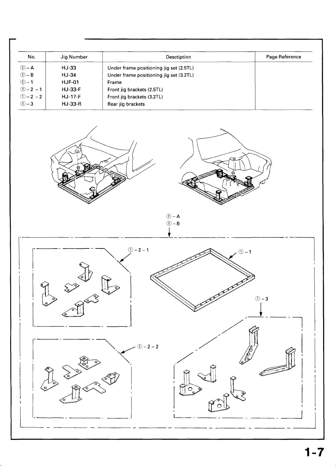
Positioning Jigs
Main Menu
Table of Contents
4-12,
4-18, 4-50, 4-55
4-12,
4-18
4-50, 4-55
Page 8
Welding Methods/Repair Tools
Main Menu
Table of Contents
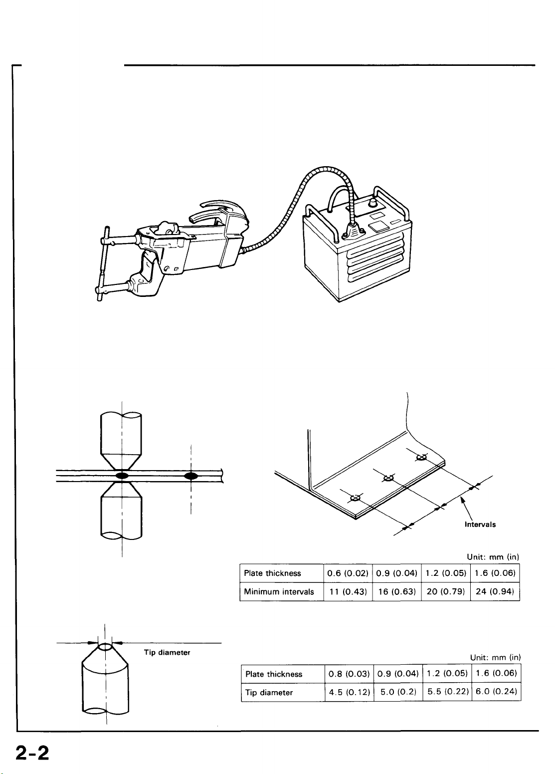
Spot Welding
Spot welding is also known as resistance spot welding, and it is the most suitable method of welding for automobiles. It has three
main features: the welding can be performed instantaneously, it exercises very little effect on the mother material, and it reduces
the generation of distortion to the absolute minimum. However, please remember to remove all paint and other impurities from
the surface of the material you intend to weld for reliable results.
Welders:
Spot welder
Welding Conditions:
When performing spot welding, make absolutely sure that you conform to the conditions governed by the current, conductivity
time, welding pressure, holding time, and shutdown time recommended for the spot welder.
Please bear in mind the following points when welding:
• Plate thickness and minimum welding pitch
NOTE: When the welding intervals are too
small, this leads to branching, making it im-
possible to maintain the desired soldering
state.
• Plate thickness and tip diameter
Timer
Page 9
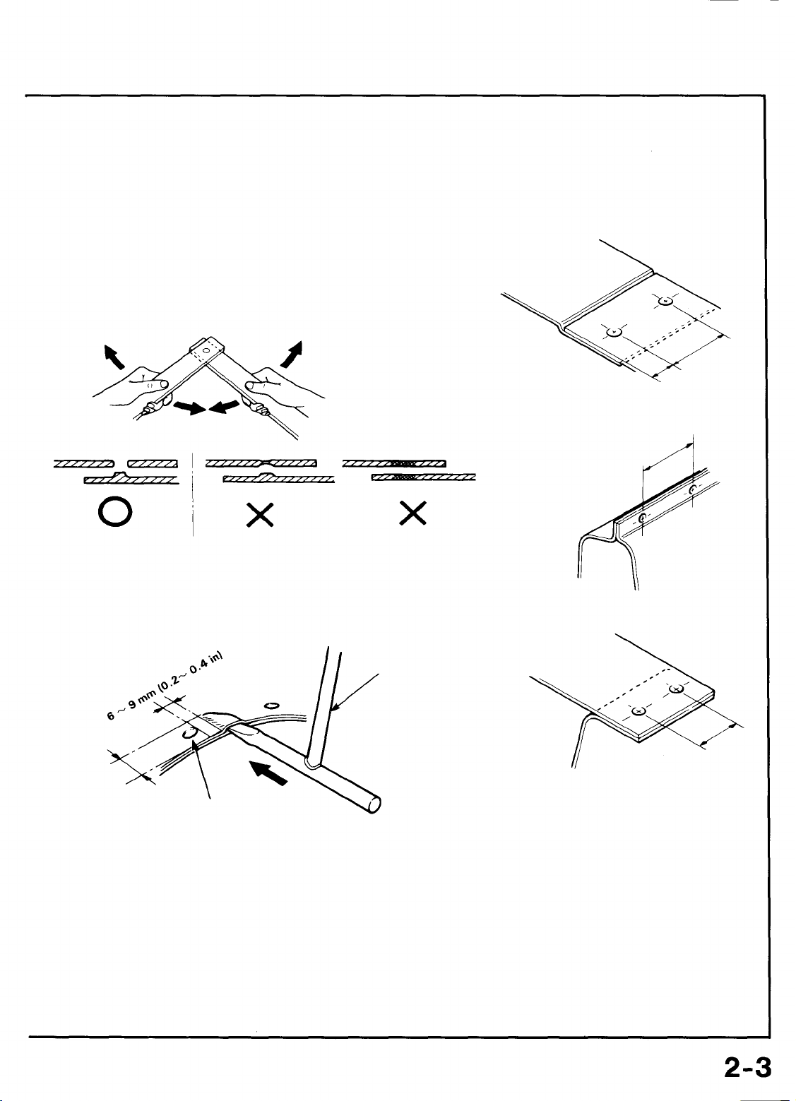
• Welding Strength Test
Main Menu
Table of Contents
Even if you perform the welding in accordance with the conditions, the strength of the welded sections may fluctuate widely with
drops in the voltage and other factors. The quality of the welding cannot be evaluated unless the welded sections are destroyed.
Provide yourself with a steel plate of the same thickness and conduct a destruction test.
• If holes appear in the steel plates, this means that the
welding is standard strength.
• Drive a wedge between two panels near the nugget. If
the welded parts do not come apart and the diameter of
the nugget is more than 3mm (0.1 in), the welding
should be satisfactory.
WEDGE
30 mm
(1.2in)
Stop inserting the wedge when
the full size of the nugget appears.
NOTE:
It is difficult to perform spot welding in the following circumstances:
• When it is not possible to remove any rust or paint attached to the welding surfaces.
• When the tip of the spot welder cannot be inserted into the welding section.
• When the welding surfaces can be seen from the outside and welding will impair the exterior appearance.
In all these cases, the gas welding method should be employed. Moreover, if it is not possible to perform spot welding because of
space restrictions, plug welding using on the arc welding method may be performed instead. For plug welding, the sections to be
welded must be close together.
Page 10
Welding Methods/Repair Tools
Main Menu
Table of Contents
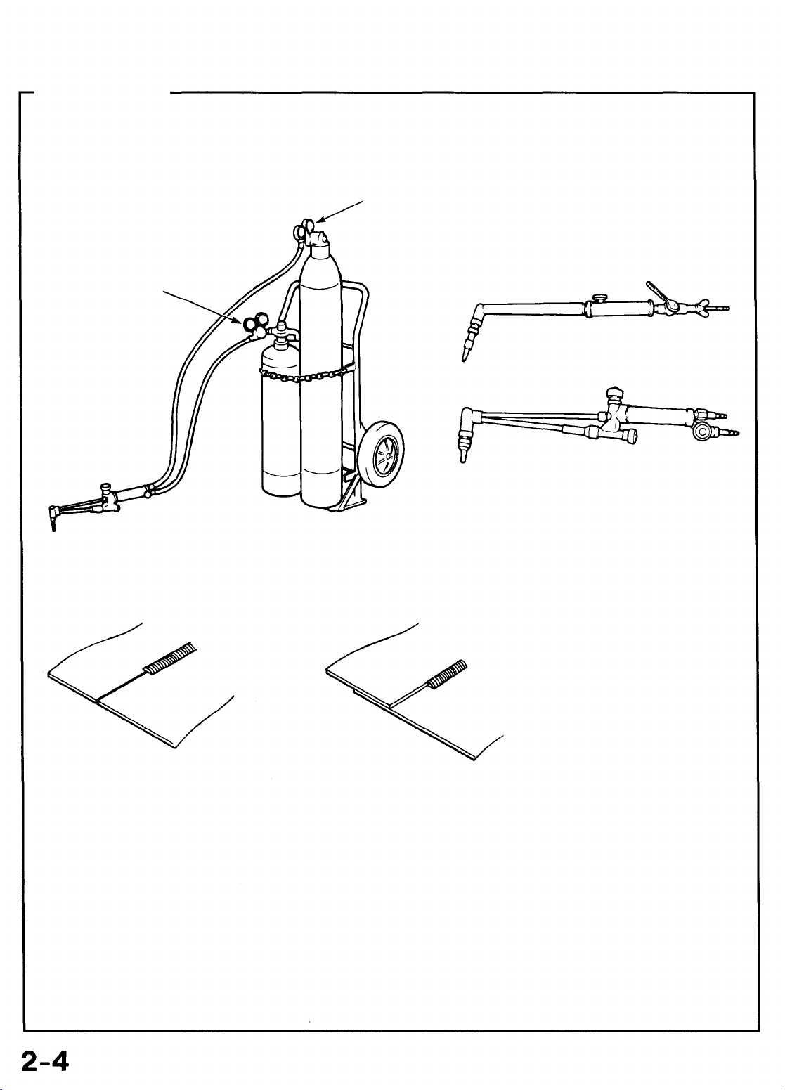
Gas Welding
Gas welding is indispensable for body repair because of the broad range of its applications for joining the body panels, cutting the
materials that construct the body, and applying heat to reform panels, and also because it is easy to get hold of the tools.
However, this method requires experience.
Welders:
Gas regulator
Welding Methods:
Gas regulator
Welder
Cutter
Oxygen/Acetylene tanks
Butt welding
Fillet welding or soldering
Page 11
Carbon Dioxide Arc Welder (MIG Arc Weld)
Main Menu
Table of Contents
This welding process uses inexpensive carbon dioxide instead of expensive inert gases as a shielding means. Consumable metal
electrodes are employed. It has a wide range of applications, including butt welding of thin plate, fillet welding, plug welding, and
MIG spot welding. In terms of the weld strength, it is also highly stable.
Welders:
CAUTION: Disconnect the negative battery cable before arc welding.
Welding Methods:
Butt Welding
Fillet welding
Spot welding Plug welding
Page 12
Welding Methods/Repair Tools
Main Menu
Table of Contents
Examples of Repair Tools
Item
Protective tools
Operator
Work
Tools, equipment used
1. Protective goggles
2. Cap
3. Ear plug
4. Shield for eyes
5. Overalls with long sleeves
6. Dust-proof mask
7. Protective apron
8. Welding gloves
9. Foot protectors
10. Safety shoes
11. Work gloves
12. Spattering guard
Processing tools
Vehicle body
Plug hole drilling
Heat-resistant
protective cover.
DRILLING BLADE, DRILL, SPOT CUTTER
PUNCH
PRESSURE
DRILL
Page 13
Flange tools
Main Menu
Table of Contents
Item
Work
Edge preparation
Tools, equipment used
Cutting tools
Cutting
AIRSAW
AIR IMPACT CUTTER
AIR JIGSAW
HANDSAW
HAND NIBBLER
CHISEL
Sanding tools
Cleaning
PLASMA CUTTER
DISC SANDER
Air type: Electric type:
BELT SANDER
Page 14
Welding Methods/Repair Tools
Main Menu
Table of Contents
Examples of Repair Tools (cont'd)
Fixing tools
Shaping tools
Item
Work
Base metal fixing
Skin panel shaping
VISE-GRIPS
HAMMERS
Tools, equipment used
SCREW CLAMP
SQUILL VISES
DOLLIES CHISEL
SNIPS/
SHEARS
Body, frame shaping
SPOONS
WELDER
BODY JACK
SLIDE HAMMER
Page 15
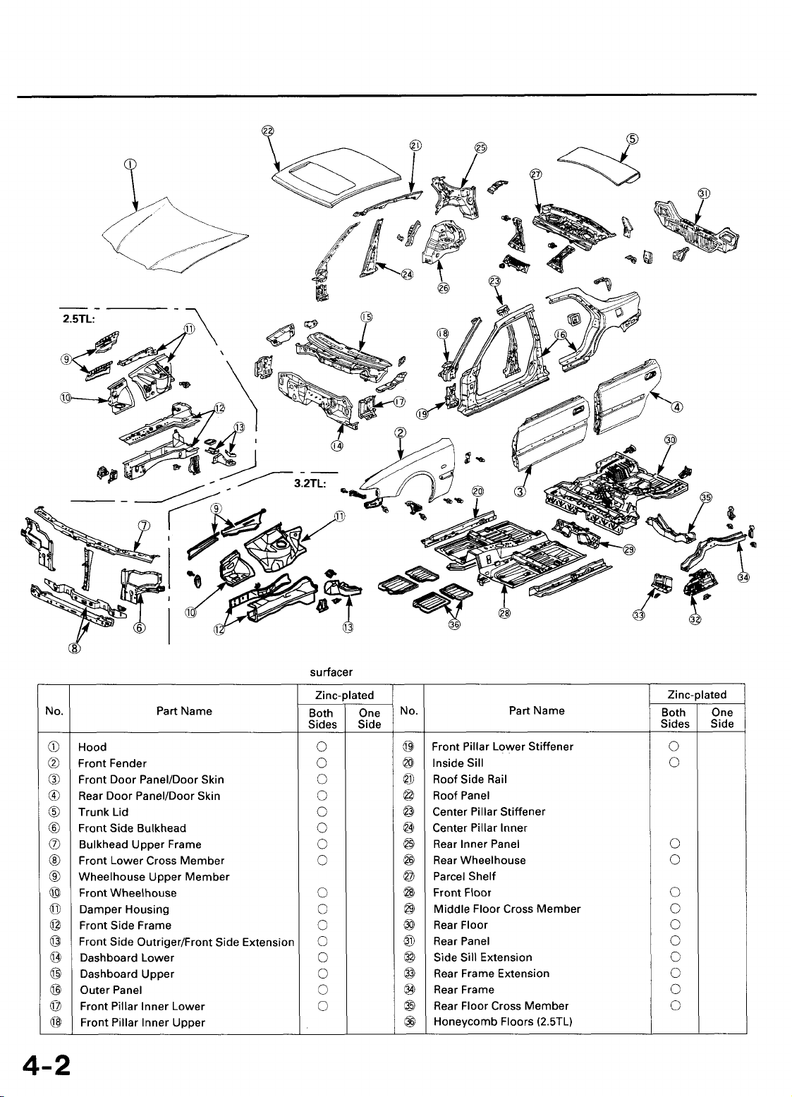
General Information
Main Menu
Table of Contents
Zinc-plated Steel Plate Repair
The zinc-plated steel plate used in some panels of the Acura 2.5TL/3.2TL requires different repair techniques than ordinary steel plate.
Refer to "Body Construction" (see page 4-2) for the location of the zinc-plated panels.
ZINC PLATING (5~6 microns)
Steel plate
1. Before spot welding the zinc-plated steel plate, remove the paint from both sides of the flange to be welded. Apply sealer to
the flange after welding.
To prevent eye injury, wear goggles or safety glasses whenever sanding, cutting or grinding.
NOTE: Seal the sanded surfaces thoroughly to prevent rust.
2. The electric continuity properties of zinc-plated steel plate is different from ordinary steel plate. When spot welding, increase
the current by 10-20%, or increase the resistance welding time.
Increase the number of weld spots by 10-20% also.
NOTE: The MIG welding procedures for zinc-plated steel plate are the same as for ordinary steel plate.
To prevent eye injury and burns when welding, wear an approved welding helmet, gloves and safety
shoes.
3. Before applying putty or body filler to the zinc-plated steel plate, sand the zinc plating thoroughly to promote adhesion and
prevent blistering.
NOTE:
• Use only epoxy-based putties and fillers on zinc-plated steel plate.
• Follow the manufacturer's specification.
4. When performing paint work, apply caulking to the ground wire
mounting position to mask the body.
SPECIAL
BOLT
CAULKING
GROUND
WIRE
GROUND WIRE
MOUNTING
HOLE
Page 16
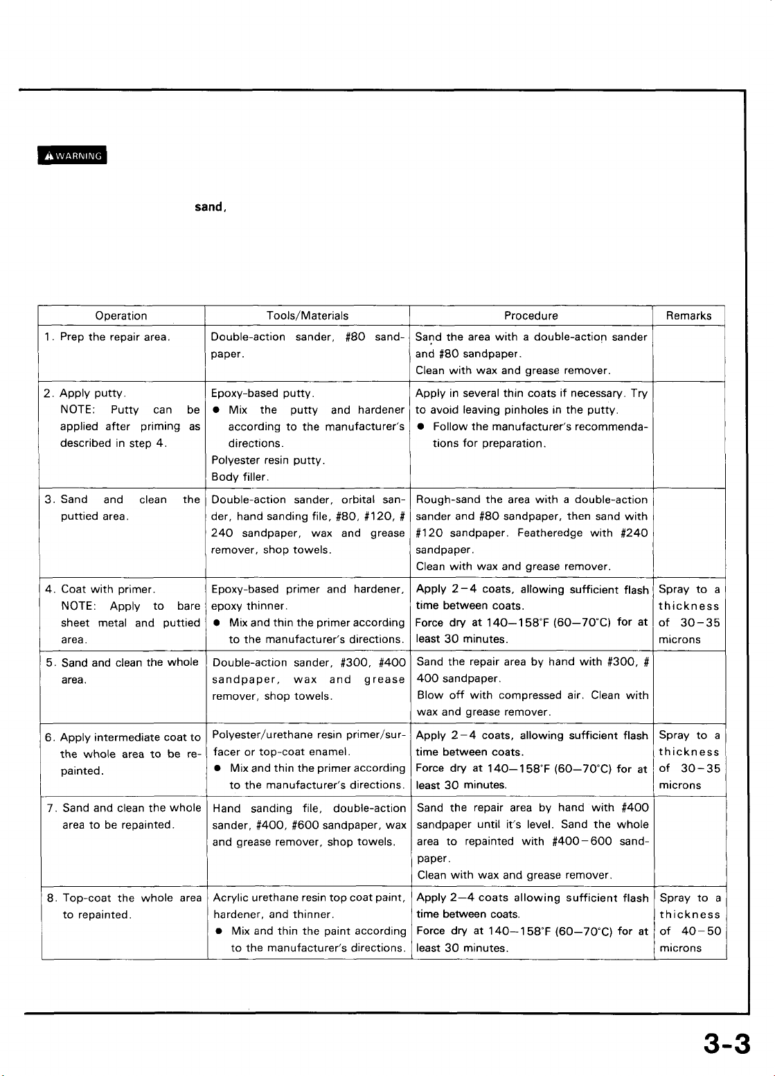
Avoid puttying as much as possible when repairing a new car. Use alternative methods as much as possible.
Main Menu
Table of Contents
• Most paints contain substances that are harmful if inhaled or swallowed. Read the paint label before opening the
container. Spray paint only in a well ventilated area.
• Cover spilled paint with
sand,
or wipe it up at once.
• Wear an approved respirator, gloves, eye protection and appropriate clothing when painting. Avoid contact with skin.
• If paint gets in your mouth or on your skin, rinse or wash thoroughly with water. If paint gets in your eyes, flush with
water and get prompt medical attention.
• Paint is flammable. Store it in a safe place, and keep it away from sparks, flames or cigarettes.
Page 17
General Information
Main Menu
Table of Contents
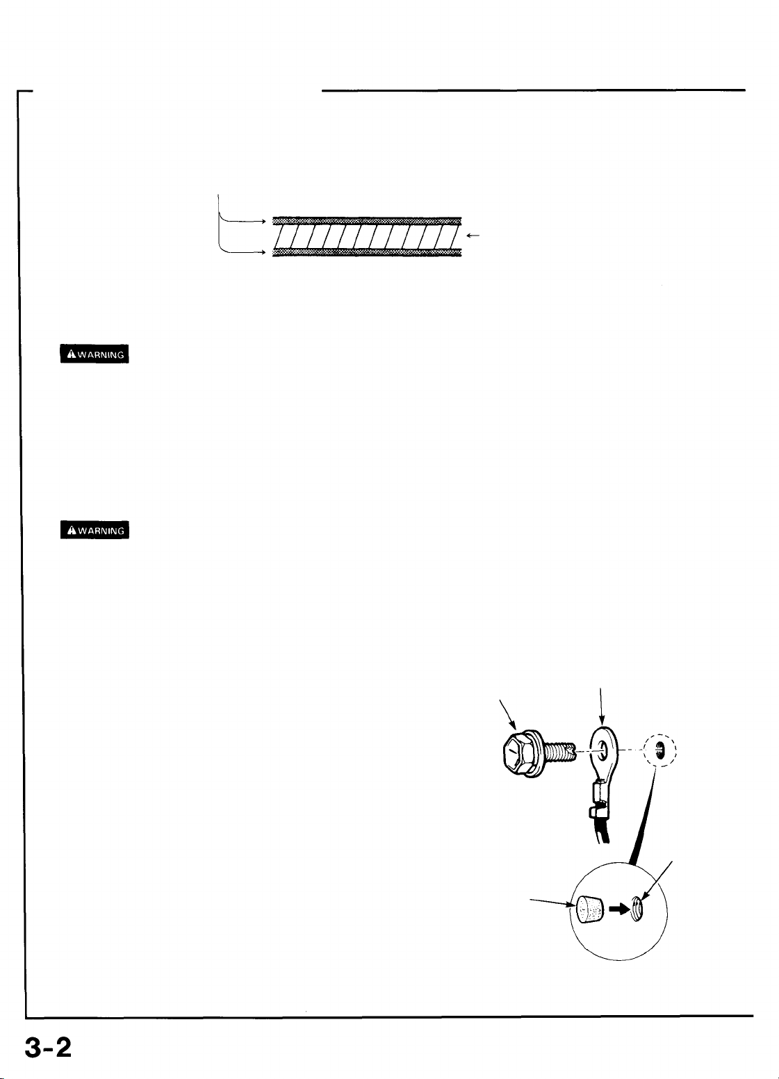
Door and Bumper Reinforcement Beams
Door and bumper reinforcement beams used on Honda automobiles are made from a metal equivalent to High Strength Steel (except
2.5TLfront
Should High Strength Steel be heated, the strength of the steel will be reduced. If High Strength Steel is damaged, as in a automobile
accident where the door reinforcement beams are bent, the beams may crack should any attempt be made to straighten them.
2.5TL
For this reason, Door and Bumper Reinforcement Beams should never be repaired, they should be replaced if they become damaged.
NOTE: If a door beam is damaged, the whole door panel assembly should be replaced.
bumper reinforcement beam).
front bumper reinforcement beam is made of aluminum alloy (#6000).
FRONT DOOR
REINFORCEMENT
BEAM
REAR DOOR
REINFORCEMENT
BEAM
2.5TL:
3.2TL:
FRONT BUMPER
REINFORCEMENT
BEAM
(Aluminum alloy)
FRONT BUMPER
REINFORCEMENT BEAM
(High Strength Steel)
REAR BUMPER
REINFORCEMENT
BEAM
(High Strength Steel)
vffMr/////////////////////^
Wmmm/mmm//////^/),
Page 18
Construction
Main Menu
Table of Contents
NOTE: Be sure to use epoxy-based putty and primer
surfacer
to make any repairs on paint coats or zinc-plated sheet metal (see page 3-3).
Page 19
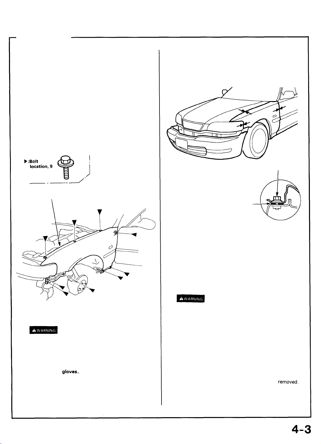
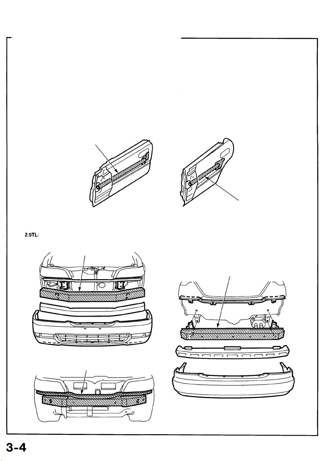
Front Fender
Main Menu
Table of Contents
Replacement
NOTE: Check clearance and level differences of the hood,
door panels and front bumper.
1.
Remove the related parts.
• Front bumper
• Headlight
• Mud guard
• Side sill panel
• Inner fender
2. Mask parts with tape.
Stick masking tape on the neighboring lower windshield
and the door to protect painted surfaces from damage.
3. Remove the front fender mounting bolts.
FRONT
FENDER
5. Set the front fender.
Fasten to the front wheelhouse at two spots with bolts.
Close the hood and check the front and rear clearances,
door clearance and level differences.
MOUNTING
BOLT
NOTE: Apply the mastic sealer
to the mounting positions of the
front fender.
MASTIC
SEALER
4. Apply paint on the back of the new fender.
See Paint Repair section
• Ventilate when spraying paint. Most paint
contains substances that are harmful if inhaled
or swallowed. Read the paint label before
opening paint container.
• Avoid contact with skin. Wear an approved
respirator,
clothing when painting.
• Paint is flammable. Store it in a safe place, and
keep it away from sparks, flames or cigarettes.
NOTE: Apply paint to lower section of front pillar also.
gloves,
eye protection and appropriate
6. After checking the mounting position, tighten all
bolts fully.
7. Apply the undercoat (see section 7
Apply an undercoat to the inside of the front fender and
upper face of the front wheelhouse.
8. Apply the paint.
See Paint Repair section.
• Ventilate when spraying paint. Most paint
contains substances that are harmful if inhaled
or swallowed. Read the paint label before
opening the paint container.
• Avoid contact with skin. Wear an approved
respirator, gloves, eye protection and appropriate
clothing when painting.
• Paint is flammable. Store it in a safe place, and
keep it away from sparks, flames or cigarettes.
9. Install the related parts.
Install in the reverse order in which they were
10. Check and adjust.
• Check wiring connections.
• Adjust the headlight aim.
).
removed.
Page 20
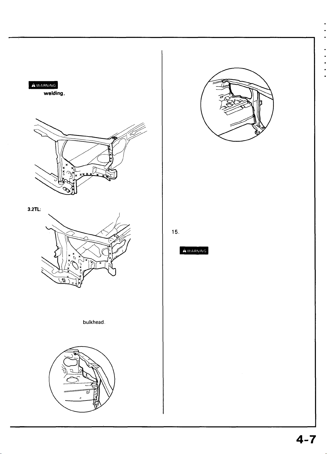
Front Bulkhead
Main Menu
Table of Contents
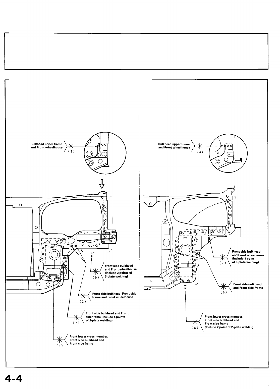
Description
The front bulkhead is joined to the front wheelhouse and front side frame. It forms the base for the headlights and other parts and
maintains the rigidity of the front section of the body. Pay particular attention to twists and parallelism and check mounting of
related parts when
Mass Production Body Welding Diagram
welding.
2.5TL:
3.2TL:
Page 21
Replacement
Main Menu
Table of Contents
1.
Remove the related parts.
• Front bumper
• Hood
• Right and left headlights
• Right and left front fenders
• Radiator, condenser
• Hood latch
NOTE: When drilling holes be careful not to drill down
to the front wheelhouse or front side frame themselves.
• Cut off the bulkhead with an air chisel, leaving the
welding flanges intact.
• Level and finish the burrs from the pried off spot
welds with a disc sander.
-1
2. Roughly pull out and straighten the damaged area.
• Check the damage to the front wheelhouse and
front side frame before removing the front bulkhead.
Use the frame staightener to roughly pull out and
repair the damaged bulkhead before removing the
bulkhead.
NOTE: Check the fit of the door, taking care not to pull
the damaged area out more than necessary.
• Use the horizontal pinch weld clamps and attach the
car to the frame straightener at the clamping points
securely.
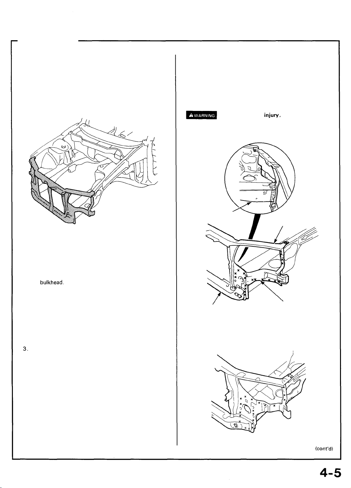
3.
Keep the body level.
Jack up the body, and place safety stands at the four
designated places of the side sills.
To prevent eye
or safety glass whenever sanding, cutting or
grinding.
2.5TL:
FRONT SIDE
FRAME
FRONT LOWER
CROSS MEMBER
3.2TL:
injury,
wear goggles
BULKHEAD UPPER
FRAME
FRONT SIDE
BULKHEAD
NOTE: Refer to the Acura
Manuals for safety stand location points.
4. Cut and pry off the front bulkhead.
• Center punch around the spot weld imprints.
• Use the special spot cutter to drill holes at the spot
weld nuggets on the front wheelhouse and front side
frame.
2.5TL/Acura
3.2TL
Service
Page 22
Front Bulkhead
Main Menu
Table of Contents
Replacement
(cont'd)
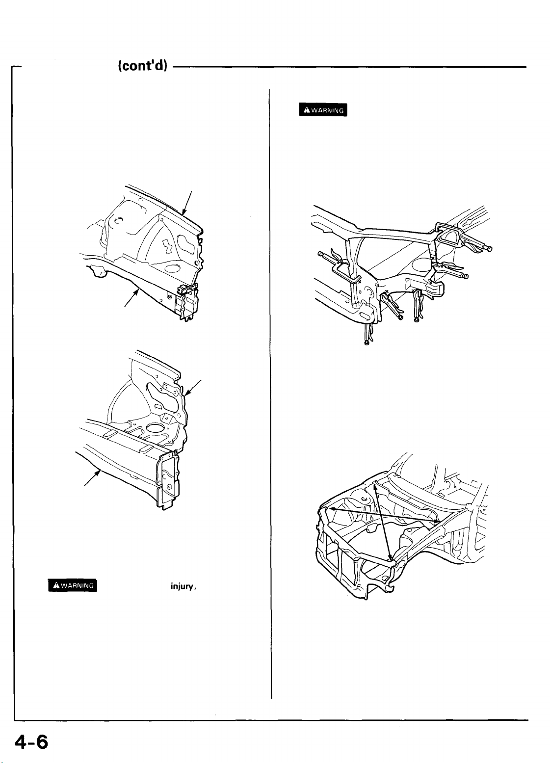
5. Mold the damaged related parts.
• Use a hammer and dolly to mold the damaged areas
of the front wheelhouse front and side frame.
• Even out the welding flanges with a hammer and
dolly.
• Fill all drilled holes by MIG or gas welding.
2.5TL:
FRONT SIDE FRAME
3.2TL:
FRONT WHEELHOUSE
FRONT
WHEELHOUSE
7. Tack weld the new front bulkhead.
To prevent eye injury and burns
when welding, wear an approved welding helmet,
gloves and safety shoes.
Spot weld the clamped sections.
NOTE: Make sure that the right and left bulkheads are
in line with each other.
8. Measure the front compartment diagonally.
Measure the front compartment diagonally with a tracking gauge or convex tool as shown to check it for
twisting or bending.
FRONT SIDE
FRAME
6. Set the new front bulkhead.
• Grind both sides of the welding section of the bulkhead with a sander to remove the undercoat and
expose the steel plate.
U^^JQQ
or safety glasses whenever sanding, cutting or
grinding.
• Clamp both the right and left sides with the visegrips as shown.
NOTE: Apply the spot sealer to the welding surface
when spot welding.
• Check the front bulkhead position using the body
dimensional drawings (see section 6).
To
prevent
eye
injury,
wear
goggles
9. Temporarily assemble the hood, headlight and front
fender, then check the clearances and level differences.
Page 23
10. Perform the main welding.
Main Menu
Table of Contents
• Spot weld the bulkhead as shown.
• Make 20% to 30% more spot welds than there were
holes drilled.
To prevent eye injury and burns
when
welding,
wear an approved welding helmet,
gloves and safety shoes.
2.5TL:
3.2TL
3.2TL:
12.
Apply the undercoat (see section
13.
Attach the front fender.
14.
Lower the body.
7).
NOTE: Tighten the wheel nuts to the specified torque.
Torque: 108
N-m
(11.0
kgf-m,
79.6
Ibf-ft)
11.
Finish the welds.
Use a hammer and dolly to even out the front wheelhouse and front side frame flanges for a close fit with
the surface of the front
bulkhead.
2.5TL:
15.
Apply the paint.
See Paint Repair section.
• Ventilate when spraying paint. Most paint
contains substances that are harmful if inhaled
or swallowed. Read the paint label before
opening the paint container.
• Avoid contact with skin. Wear an approved
respirator, gloves, eye protection and appropriate
clothing
when
painting.
• Paint is flammable. Store it in a safe place, and
keep it away from sparks, flames or
cigarettes.
16. Install the related parts.
17.
Inspect, check, and make adjustments.
• Adjust the headlight aim.
• Check that the electical components light up and
operate properly.
• Replenish radiator coolant and inspect for leaks.
Page 24

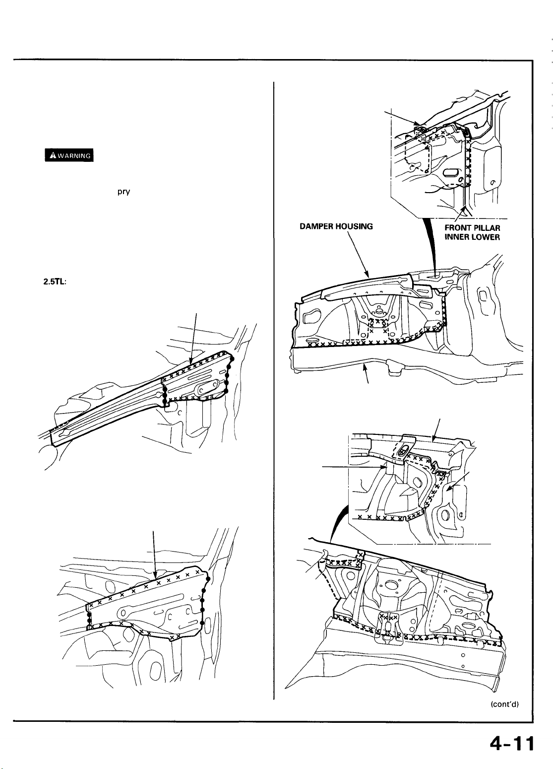
Front Wheelhouse/Damper Housing
Main Menu
Table of Contents
Description
The front wheelhouse component is constructed as a unit with the front damper housing. Therefore, replacement of the
component affects the front wheel alignment. When assembling it, either use a positioning jig or follow dimensions on the
frame repair chart for positioning. Weld carefully.
Page 25
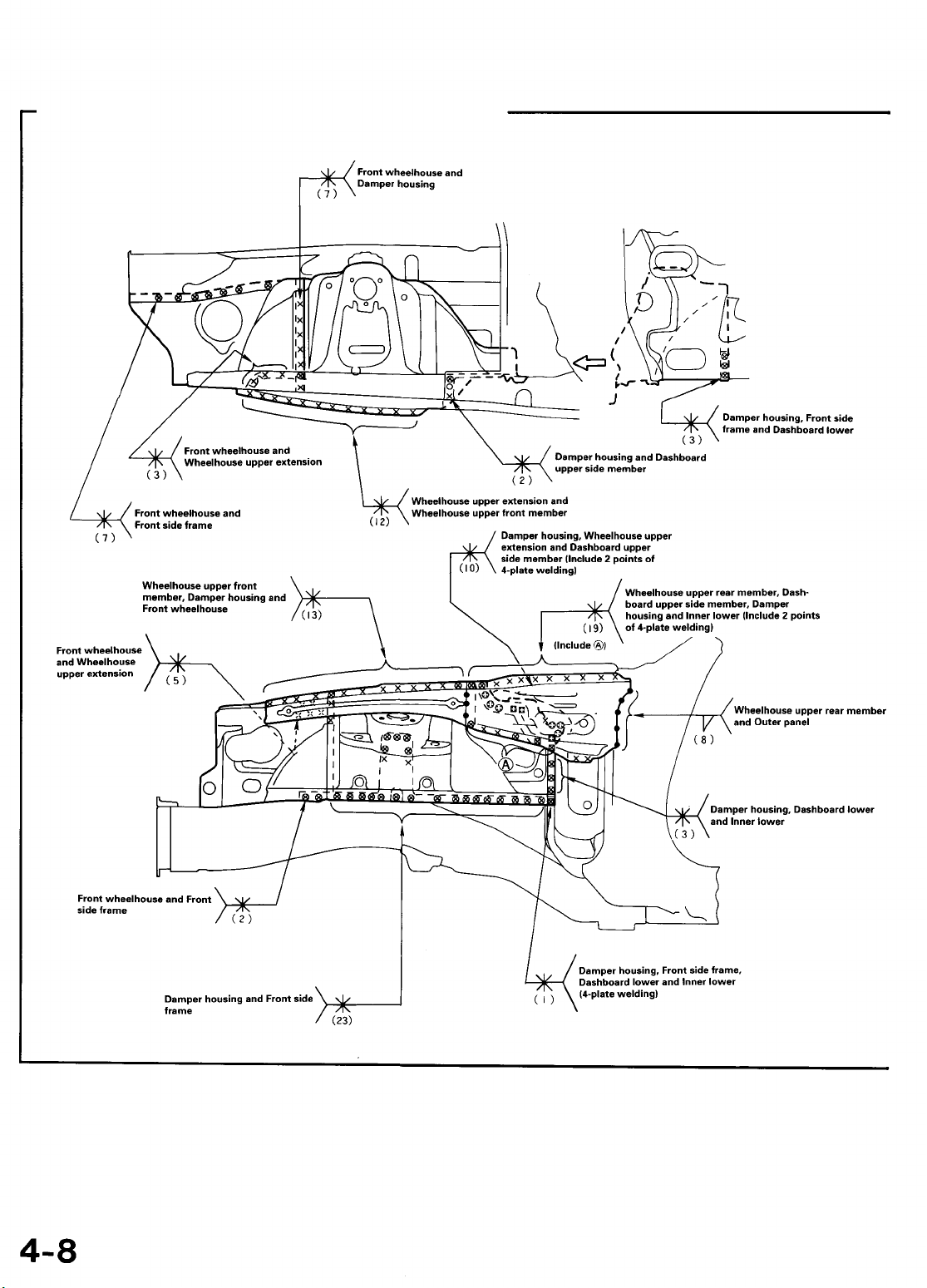
Front Wheelhouse/Damper Housing
Main Menu
Table of Contents
Mass Production Body Welding Diagram
2.5TL:
Page 26
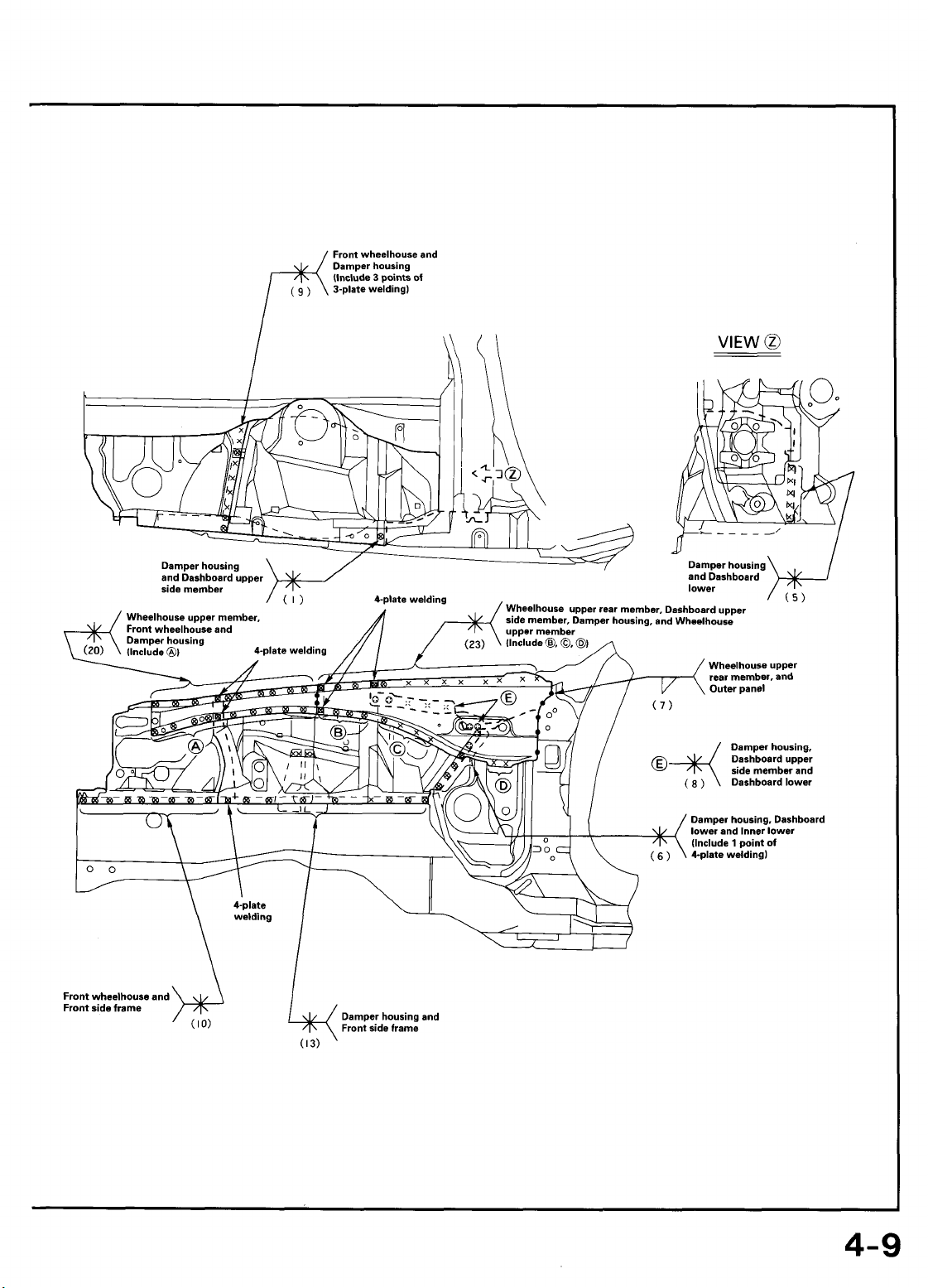
3.2TL:
Main Menu
Table of Contents
Page 27
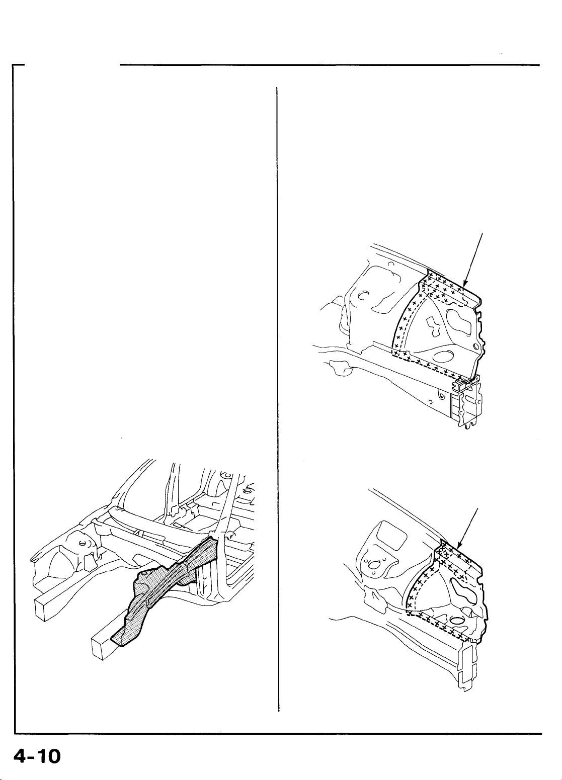
Front Wheelhouse/Damper Housing
Main Menu
Table of Contents
Replacement
1.
Remove the related parts.
• Parts to be removed when removing the front bulkhead
• Parts on passenger side of lower dashboard which
are especially flammable
• Electrical accessories in engine compartment and
wire harnesses.
2.5TL
NOTE: See the 95-96 Acura
Service Manuals, for removal and installation of the
engine, front suspension and brakes.
2. Pull out and straighten the damaged area to approximately the original shape.
• Attach the car to the frame straightener by tightening the underbody clamps at the horizontal pinch
weld points.
NOTE: Refer to the 95-96 Acura 2.5TL & 96 Acura 3.2TL
Service Manuals for safety stand location points.
• Before cutting off the damaged sections, pull them
out so that they are restored to the original shape.
• Do not pull out more than necessary.
• Pull out and straighten the damaged area of the
lower dashboard, front pillar, and other parts.
• After pulling, check the damper housing position
using the body dimensional drawings (see section 6)
and positioning jig (see page 1-7).
& 96 Acura
3.2TL
4. Cut and pry off the front wheelhouse and damper
housing.
-1.
When replacing the front wheelhouse only.
• Center punch around the spot weld imprints on the
front side frame and damper housing.
• Drill holes in the center punched areas using a spot
cutter.
• Using a chisel, pry off the welded flange.
2.5TL:
FRONT WHEELHOUSE
NOTE: Check the condition of the door and hinges.
3. Peel off the undercoat.
Heat the undercoat at the weld areas of the wheelhouse
and front side frame with a gas torch, and peel off the
undercoat with a metal spatula.
3.2TL:
FRONT WHEELHOUSE
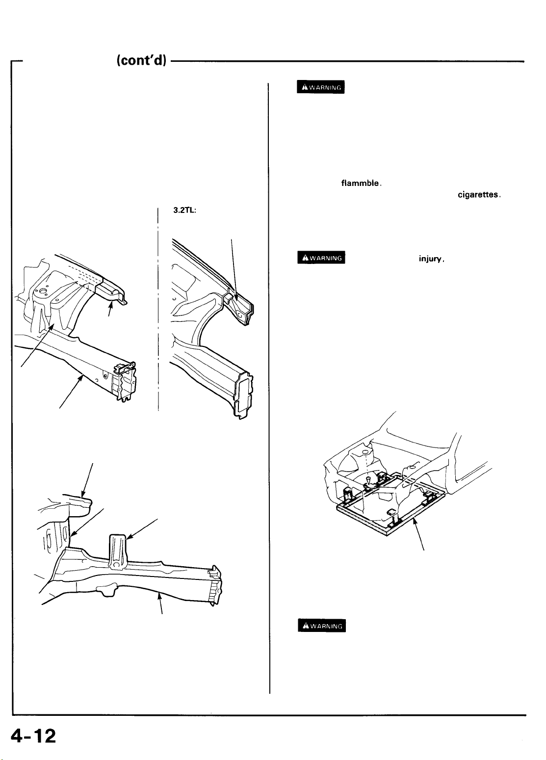
Page 28
-2.
Main Menu
Table of Contents
Replace the damper housing with the front
wheelhouse.
• Remove the wheelhouse upper rear member.
• Remove the MIG weld flange with a disc sander.
To prevent eye injury, wear goggles or
safety glasses whenever sanding, cutting or grinding.
2.5TL:
DASHBOARD
UPPER SIDE
MEMBER
• Using a chisel,
front pillar and damper housing.
NOTE: Remove the wheelhouse upper rear member
carefully so they can be reused.
2.5TL:
pry
off the welded flange form the
WHEELHOUSE UPPER
REAR MEMBER
3.2TL:
DAMPER
HOUSING
FRONT SIDE FRAME
DASHBOARD UPPER SIDE MEMBER
FRONT PILLAR
INNER LOWER
3.2TL:
WHEELHOUSE UPPER
REAR MEMBER
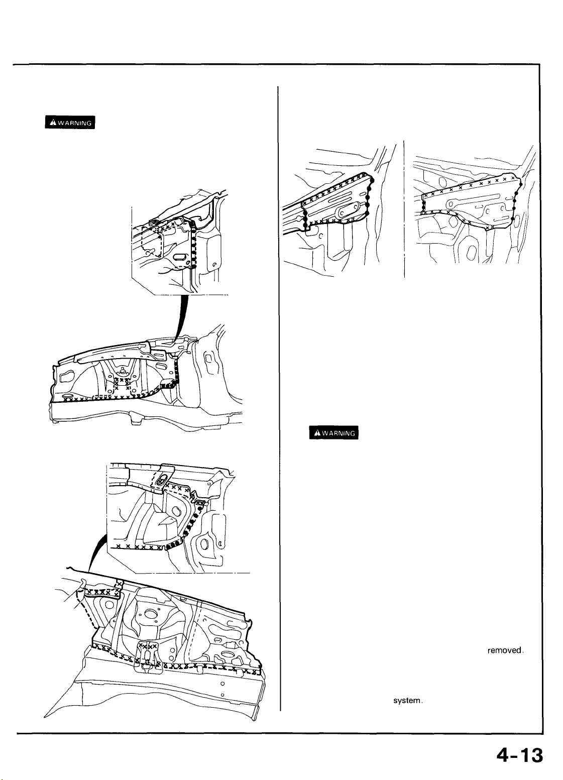
Page 29
Front wheelhouse/Damper housing
Main Menu
Table of Contents
Replacement
5. Mold the related parts.
• Level and finish the burrs left on the welding
surfaces with a sander.
• Fill all drilled holes by MIG or gas welding.
Use a hammer and dolly to even out the welded areas of
the lower dashboard, front side frame and dashboard
upper side member.
2.5TL:
DAMPER
HOUSING
FRONT SIDE FRAME
(cont'd)
3.2TL:
WHEELHOUSE UPPER
MEMBER DIAGONAL
WHEELHOUSE
UPPER
EXTENSION
• Ventilate when spraying paint. Most paint
contains substances that are harmful if inhaled
or swallowed. Read the paint label before
opening the paint container.
• Avoid contact with
respirator, gloves, eye protection and appropriate
clothing when painting.
• Paint is
• Remove the undercoat from both sides of the weld-
or safety glasses whenever sanding, cutting or
grinding.
• Clamp to the front side frame with vise-grips and
NOTE: Apply the spot sealer to the welding surface
when spot welding.
• Clamp the front bulkhead with vise-grips.
• Measure the front compartment diagonally.
NOTE: Use of a positioning jig is recommended (see
page 1-7).
flammble.
keep it away from sparks, flames or
ing section and expose the steel plate using a disc
sander.
squill vises.
skin.
Wear an approved
Store it in a safe place, and
To prevent eye
injury,
wear goggles
cigarettes.
DASHBOARD UPPER
SIDE MEMBER
DASHBOARD LOWER
DAMPER STIFFENER
FRONT SIDE FRAME
6. Set the new front wheelhouse and damper housing.
• Apply body paint to both sides of the new front
wheelhouse and damper housing.
• See Paint Repair section.
POSITIONING JIG
• Spot weld several points in the clamped sections, and
temporarily attach the front wheelhouse and damper
housing.
To prevent eye injury and burns
when welding, wear an approved welding helmet,
gloves and safety shoes.
7. Check the dimensions, temporarily install the hood, front
fender and headlight, and check for differences in level
and clearance.
Page 30
8. Perform the main welding.
Main Menu
Table of Contents
• Weld as much as possible with the jig still
To prevent eye injury and burns
when welding, wear an approved welding helmet,
gloves and safety shoes.
• Make 20% to 30% more spot welds than there were
holes drilled.
2.5TL:
mounted.
9. Weld the wheelhouse upper rear member.
When the upper rear member is to be reused, make MIG
welds at the drilled holes.
2.5TL:
10. Finish the welded area.
Use a hammer and dolly to even out the side bulkhead
and front side frame flanges for close fit with the surface
of the front wheelhouse and damper housing.
11. Apply the sealer (see section 5).
Apply sealer to the mating surfaces of the lower
dashboard and front side frame, etc.
3.2TL:
3.2TL:
12. Apply the paint.
See Paint Repair section.
• Ventilate when spraying paint. Most paint
contains substances that are harmful if inhaled
or swallowed. Read the paint label before
opening the paint container.
• Avoid contact with skin. Wear an approved
respirator, gloves, eye protection and appropriate
clothing when painting.
• Paint is flammable. Store it in a safe place, and
keep it away from sparks, flames or cigarettes.
13. Apply the undercoat.
Undercoat the front floor, etc, and apply anti-rust agent
to the inside of the welding section of the front side
frame, lower dashboard, and upper member, etc (see
section 7).
14. Install the related parts.
Install in the reverse order in which they were
15. Inspect, check and make adjustment.
• Measure the front wheel alignment.
• Inspect the brake
• Adjust the headlight aim.
system.
removed.
Page 31

Front Side Frame
Main Menu
Table of Contents
Description
The front side frame acts as a base for the front suspension and is highly important in maintaining the rigidity of the front section.
Pay careful attention to the position and dimensions of the weld joints and weld carefully.
Page 32

Front Side Frame
Main Menu
Table of Contents
Mass Production Body Welding Diagram
2.5TL:
NOTE: Replace the front side frame and front side outrigger as an assembly.
Page 33

3.2TL:
Main Menu
Table of Contents
NOTE: Replace the front side frame and front side extension
as an assembly.
Page 34

Front Side Frame
Main Menu
Table of Contents
Replacement
1. Remove the related parts.
• Front suspension related parts
• Brake hoses and pipes
• Engine compartment electrical components
• Fittings in passenger compartment, etc.
• Steering gearbox.
2. Remove the sub-frame.
NOTE: With the front bulkhead removed.
3. Roughly pull out and straighten the damaged area.
• Attach the car to the frame straightener by tightening the underbody clamps located at the horizontal
pinch welds.
NOTE: Refer to the 95-96 Acura 2.5TL & 96 Acura 3.2TL
Service Manuals for safety stand location points.
• Before cutting off the damaged sections, pull them
out so that they are restored to the original shape.
• Cutting off the front side frame before roughly
pulling out the damage makes repair of the related
front floor, lower dashboard, and other related parts
difficult.
4. Peel off the undercoat.
Heat the undercoat at the weld areas of the lower
dashboard, front floor and side sill with a gas torch and
peel off the undercoat with a metal spatula.
CAUTION: Be careful not to burn the fittings inside
the passenger compartment when heating.
5. Remove the front side frame.
NOTE: It's not necessary to separate the front wheel-
house from the front side frame if the wheelhouse/
damper housing is to be replaced also.
• Center punch around the spot weld imprints on the
wheelhouse, damper housing, lower dashboard, front
floor and floor frame.
• Using a spot cutter, drill holes in the spot welded
areas.
• Peel off the welding flange using the chisel.
Page 35

Remove the burrs from the drilled sections with a
Main Menu
Table of Contents
disc sander.
To prevent eye injury, wear goggles
or safety glasses whenever sanding, cutting or
grinding.
NOTE: When drilling holes and be careful not to
drill down to the inside sill.
2.5TL:
• Center punch around the spot weld imprints on the
front side frame and front side outrigger from inside
the passenger compartment.
• Drill holes in the spot welded area with a 5 mm (0.2 in)
drill.
NOTE: Drill holes completely through the parts since the
replacement front side frame, front side outrigger and jack-up
stiffener will be welded by MIG welding.
• Remove the MIG welds of the front side frame-and-lower
dashboard with a disc sander.
Page 36

Front Side Frame
Main Menu
Table of Contents
Replacement (cont'd)
7. Set the new front side frame.
• Remove the undercoat from the both sides of the
welding section, and expose the steel plate using a
disc sander.
To prevent eye injury, wear goggles
or safety glasses whenever sanding, cutting or
grinding.
NOTE: Apply the spot sealer to the welding surface
when spot welding.
• Tighten the front side frame against the front floor
and side sill using vise-grips or pliers.
• Place a jack under the front side frame end and
support it, and measure the positions for temporary
attachment.
NOTE: Use of a positioning jig is recommended (see
page 1-7).
6. Mold the related parts.
• Reshape the front wheelhouse and damper housing
lower dashboard-to-front floor joint using a hammer
and dolly.
• Fill all drilled holes by MIG or gas welding.
• Clamp the front bulkhead and front wheelhouse/
damper housing with squill vises and vise-grips.
• Measure the front compartment diagonally.
• Spot weld several points in the clamped sections,
and temporarily attach the front side frame.
To prevent eye injury and burns
when welding, wear an approved welding helmet,
gloves and safety shoes.
• Check the body dimensions (see section 6).
Page 37

8. Perform the main welding.
Main Menu
Table of Contents
• Make 20% to 30% more spot welds than there were
holes drilled.
• Weld as much as possible with the jig still mounted.
To prevent eye injury and burns
when welding, wear an approved welding helmet,
gloves and safety shoes.
• Weld the front side frame, wheelhouse, damper
housing and bulkhead.
3.2TL:
• From the passenger compartment side, plug weld
the holed areas of the lower dashboard and front
floor with a MIG welder.
2.5TL:
• and make 5 mm (0.2 in) holes in the MIG weld
holes with the outrigger, and plug weld the inside sill
with a MIG welder.
2.5TL:
Page 38

Front Side Frame
Main Menu
Table of Contents
Replacement (cont'd)
3.2TL:
9. Finish the welds.
Use a hammer and dolly to even out the damper housing,
wheelhouse, lower dashboard, front bulkhead and side
sill flanges for a close fit with the surface of the front side
frame.
12. Apply the undercoat.
Undercoat the front floor, and apply anti-rust agent to
the inside of the welding section of the side sill, front side
frame, etc (see section 7).
13. Install the related parts.
Install in the reverse order in which they were removed.
14. Inspect, check and adjust.
• Measure the front wheel alignment.
• Inspect the brake system.
• Adjust the headlight aim.
10. Apply the sealer (see section 5).
Apply sealer to the mating surfaces of the lower dash-
board, etc.
11. Apply the paint.
See Paint Repair section.
Ventilate when spraying paint. Most paint
contains substances that are harmful if inhaled
or swallowed. Read the paint label before
opening the paint container.
Avoid contact with skin. Wear an approved
respirator, gloves, eye protection and appropriate
clothing when painting.
Paint is flammable. Store it in a safe place, and
keep it away from sparks, flames or cigarettes.
Page 39

Front Side Outrigger/Front Side Extension
Main Menu
Table of Contents
Description
The front side outriggers connect the front side frames to the body and are vital to the rigidity of the entire body frame. Pay
particular attention when welding the front side outriggers from beneath the front floor and side sill.
Page 40

Front Side Outrigger/Front Side Extension
Main Menu
Table of Contents
Mass Production Body Welding Diagram
2.5TL:
NOTE: Replace the front side outrigger, locating bracket and front side brace as an assembly.
Page 41

Front side Outrigger/Front Side Extension
Main Menu
Table of Contents
Mass Production Body Welding Diagram (cont'd)
3.2TL:
Page 42

Replacement
Main Menu
Table of Contents
1. Remove the related parts.
• Front seat
• Carpet
• Refer to the front side frame (see page 4-16).
2. Pull out and straighten the damaged area.
• The front side outrigger receives impact through the
front side frame or side sill. Such impact generally
requires replacement of all these parts.
• Before cutting off the front side outrigger or side sill,
pull out the damaged area with the frame straightener and correct the related parts such as the front
floor and dashboard. Check the clearance and level
differences of the front doors.
• Jack up the body and place safety stands at the four
designated places of the side sills. If necessary,
place safety stands at the rear of the frame.
3. Peel off the undercoat.
Heat the undercoat at the weld areas of the front side
outrigger and side frame with a gas torch and peel off the
undercoat with a metal spatula.
CAUTION: Be careful not to burn the fittings inside
the passenger compartment when heating.
4. Remove the front side outrigger.
• Center punch around the spot weld imprints on the
front side outrigger from inside the passenger compartment.
• Drill holes is the spot welded areas with a 5 mm (0.2
in) drill.
• Remove the MIG welds with a disc sander.
NOTE: Drill holes through the parts completely since the
replacement front side outrigger will be welded by MIG
welding.
• Center punch around the spot weld imprints on the
front side frame, floor frame and inside sill.
• Drill holes using a spot cutter.
NOTE: When drilling holes be careful not to drill down to
the front side frame, floor frame and inside sill.
Page 43

Front Side Outrigger/Front Side Extension
Main Menu
Table of Contents
Replacement (cont'd)
3.2TL:
FRONT SIDE
FRONT SIDE
FRAME
FLOOR FRAME
Level off and finish the burrs of the pried off spot
welds with a disc sander.
To prevent eye injury, wear goggles
or safety glasses whenever sanding, cutting or
grinding.
EXTENSION
6. Set the new front side outrigger.
• Remove the undercoat from both sides of the areas
to be spot welded with a sander to expose the steel
plate.
• Clamp the weld flanges with the side sill using the
vise-grip pliers. Set the front side outrigger on the
side frame using a jack.
• Drill 3 mm (0.12 in) holes, and screw 5 mm selftapping screws into the drilled holes at the areas
where the front side outrigger does not fit closely.
• Even out the welded flange and damaged area with
a hammer and dolly.
7. Perform the main welding.
To prevent eye injury and burns
when welding, wear an approved welding helmet,
gloves and safety shoes.
• From the passenger compartment side, weld the
holes in the lower dashboard, front floor and floor
frame with a MIG welder.
• Weld the front side frame and front side outrigger
using MIG welds.
2.5TL:
5. Mold the related parts.
Reshape the lower dashboard, front side frame, front
floor, inside sill and side sill inner joint using a hammer
and dolly.
2.5TL:
Remove the remains of
the front side outrigger.
FRONT SIDE FRAME
Page 44

Make 5 mm (0.2 in) holes in the MIG weld holes with
Main Menu
Table of Contents
the outrigger or front side extension, and weld the
front side frame, floor frame and inside sill with a MIG
welder.
2.5TL:
8. Apply the sealer (see section 5).
Apply sealer to the mating surface of the lower dash-
board and front floor.
9. Apply the paint.
See Paint Repair section.
6 point of MIG welding the bending angle of a flange.
Welding pitch=30 mm (1.2 in)
3.2TL:
• Ventilate when spraying paint. Most paint
contains substances that are harmful if inhaled
or swallowed. Read the paint label before
opening the paint container.
• Avoid contact with skin. Wear an approved
respirator, gloves, eye protection and appropriate
clothing when painting.
• Paint is flammable. Store it in a safe place, and
keep it away from sparks, flames or cigarettes.
10. Apply the undercoat.
Undercoat the front floor, etc, and apply anti-rust agent
to the inside of the front side outrigger and side sill (see
section 7).
Page 45

Front Pillar (Outer Panel)
Main Menu
Table of Contents
Description
The front pillar is connected to the roof, windshield, the door hinges, and side sills and is a highly important support. Connection
of the front pillar determines the position of the windshield and front door. Align the front fender, door, and windshield while
the front pillar is loosely mounted, and check the clearances and level differences.
Mass Production Body Welding Diagram
Page 46

Replacement
Main Menu
Table of Contents
1. Remove the related parts:
• Hood
• Front fender
• Front door
• Windshield
• Front side trim
• Door opening trim
• Side cowl lining
• Dashboard
• Front pillar trim
• Wire harness, etc.
• Steering column
• Steering hanger pipe
NOTE: Make sure that the right and left pillars are
parallel with the windshield surface. Check the door for
proper opening and closing.
2. Pull out and straighten the damaged area.
• Pull out the damaged area with the frame straightener before cutting off the front pillar extension and
front pillar.
NOTE: Pull out until the pillar is lined up with the
surface of the windshield.
• With the pillar pulled out, pull out and straighten the
related lower dashboard and floor section.
• After pulling, check the inner pillar position using the
body dimensional drawings (see section 6).
4. Cut off the front pillar.
• Cut off the front pillar along the bold line shown in
the figure to the right with a gas cutter.
• Use a handsaw to cut the windshield and side sill
areas.
NOTE: Be careful not to cut the inner section.
• Center punch around the spot weld imprints.
• Drill holes using a spot cutter.
• Chisel off the weld flanges.
• Finish the burrs at the drilled areas with a disc
sander.
To prevent eye injury, wear goggles
or safety glasses whenever sanding, cutting or
grinding.
OUTER
PANEL
UPPER
STIFFENER
INSIDE SILL
INNER
UPPER
3. Remove the wheelhouse upper rear member.
WHEELHOUSE
UPPER REAR MEMBER
OUTER PANEL
Repair the front pillar lower stiffener if necessary.
FRONT INNER UPPER
PILLAR
FRONT PILLAR LOWER
STIFFENER
Page 47

Front Pillar (Outer Panel)
Main Menu
Table of Contents
Replacement (cont'd)
5. Mold the related parts.
Fill any holes by MIG or gas welding, and even out with a
hammer and dolly.
To prevent eye injury and burns
when welding, wear an approved welding helmet,
gloves and safety shoes.
6. Set the repair part
• Align the repair part with the top cut section, then
cut it with a handsaw.
NOTE: Cut the side sill joint with a handsaw leaving an
overlap of 30 mm (1.2 in).
• Remove the undercoat from both sides of the areas
to be spot welded with a sander to expose the steel
plate.
NOTE: Apply the spot sealer to the welding surface
when spot welding.
• Clamp with vise-grips as shown.
• Check the body dimensions (see section 6).
8. Temporarily mount the door and front fender.
• Remove the vise-grips, then mount the door.
• Check the clearance and level differences of the
door and fender.
9. Perform main welding.
• Weld the front pillar and side sill outer joints with a
MIG welder.
• Make 20% to 30% more spot welds than there were
holes drilled.
To prevent eye injury and burns
when welding, wear an approved welding helmet,
gloves and safety shoes.
• Make 5 mm (0.2 in) holes in the MIG weld holes
with the repair part, and weld the lower stiffener
extension, lower stiffener and dashboard upper side
member with a MIG welder.
REPAIR PART
FRONT PILLAR
LOWER STIFFENER
7. Tack welds the clamped sections.
To prevent eye injury and burns
when welding, wear an approved welding helmet,
gloves and safety shoes.
• Weld the wheelhouse upper rear member.
WHEELHOUSE
UPPER REAR MEMBER
Page 48

10. Finish the welding areas.
Main Menu
Table of Contents
• Finish grind the finishing allowance with a disc
sander until it is smooth.
To prevent eye injury, wear goggles
or safety glasses whenever sanding, cutting or
grinding.
• Smooth the flanged section of the door opening
with a hammer and dolly.
11. Apply the sealer (see section 5).
12. Apply the paint.
See Paint Repair section.
• Ventilate when spraying paint. Most paint
contains substances that are harmful if inhaled
or swallowed. Read the paint label before
opening the paint container.
• Avoid contact with skin. Wear an approved
respirator, gloves, eye protection and appropriate
clothing when painting.
• Paint is flammable. Store it in a safe place, and
keep it away from sparks, flames or cigarettes.
13. Apply anti-rust agent to the inside of the front pillar,
wheelhouse upper member and side sill (see section 7).
14. Install the related parts.
• Install in the reverse order of removal.
• Check the door for proper installation and level
difference from the fenders.
15. Clean and check.
• After installing the dashboard, check the lights and
gauges for proper operation.
• Clean the passenger compartment and check for
water leaks.
Page 49

Windshield Lower
Main Menu
Table of Contents
Description
Impact damage to the windshield lower area may spread to
the back of the panel and wiper mounting area, calling for
replacement of the affected skins.
Mass Production Body Welding Diagram
Page 50

Windshield Lower
Main Menu
Table of Contents
Replacement
1. Remove the related parts.
Wiper arm and motor
Windshield
Right and left front fenders
Right and left front door opening trims
Front pillar trim
Hood
Dashboard, etc
Wire harnesses and electrical accessories
Steering column
2. Cut the windshield lower and separate the welded
flange.
• Center punch around the spot weld imprints.
• Drill holes with a spot cutter through the nuggets.
• Peel off the welding flange using a chisel.
• Level off and finish the burrs of the pried-off spot
welds with a sander.
To prevent eye injury, wear goggles
or safety glasses whenever sanding, cutting or
grinding.
WINDSHIELD LOWER
A/C DUCT SHELTER
LOWER SUPPORT
CENTER DEFROSTER
DUCT
DASHBOARD
UPPER
WINDSHIELD
LOWER
Page 51

LOWER SUPPORT
Main Menu
Table of Contents
A/C DUCT
SHELTER
DASHBOARD UPPER
3. Set the new windshield lower.
• Apply an undercoat and body paint to the inside.
DASHBOARD
UPPER SIDE
BULKHEAD
CENTER
DEFROSTER
DUCT
6. Finish the welding section.
Smooth the mating surface with the windshield with a
hammer and dolly.
• Ventilate when spraying paint. Most paint
contains substances that are harmful if inhaled
or swallowed. Read the paint label before
opening the paint container.
• Avoid contact with skin. Wear an approved
respirator, gloves, eye protection and appropriate
clothing when painting.
• Paint is flammable. Store it in a safe place, and
keep it away from sparks, flames or cigarettes.
• Sand off the undercoat down to the metal from both
flanges to be welded.
• Clamp the new windshield lower in place with visegrips and squill vises.
NOTE: Apply the spot sealer to the welding surface
when spot welding.
• Install the new windshield and check for proper
installation and alignment.
4. Tack weld the new windshield lower.
To prevent eye injury and burns
when welding, wear an approved welding helmet,
gloves and safety shoes.
• Remove the vise-grips and install the fender and
hood. Check for differences in level and clearance.
5. Perform the main welding.
• Make 20% to 30% more spot welds than there were
holes drilled.
To prevent eye injury and burns
when welding, wear an approved welding helmet,
gloves and safety shoes.
7. Apply the sealer (see section 5).
Apply sealer to the upper dashboard, pillars, etc.
8. Install the front fender and hood.
Check the front fender and hood for differences in level
and clearance.
9. Apply the paint.
See Paint Repair section.
• Ventilate when spraying paint. Most paint
contains substances that are harmful if inhaled
or swallowed. Read the paint label before
opening the paint container.
• Avoid contact with skin. Wear an approved
respirator, gloves, eye protection and appropriate
clothing when painting.
• Paint is flammable. Store it in a safe place, and
keep it away from sparks, flames or cigarettes.
10. Apply anti-rust agent to the inside of the windshield
lower and dashboard upper (see section 7).
11. Install the related parts.
Install in the reverse order of removal.
NOTE: Take care not damage the windshield and the
paint finishes.
12. Inspect and clean.
• Check the windshield for water leaks.
• After installing the dashboard, check the lights,
gauges, etc. for proper operation.
• Clean the interior.
Page 52

Side Sill (Outer Panel)
Main Menu
Table of Contents
Description
The side sill should, depending on the degree of damage, be repaired as much as possible rather than replaced. (Repair by pulling
out with slide hammer with pin and washer welded on.)
Mass Production Body Welding Diagram
Page 53

Replacement
Main Menu
Table of Contents
1. Remove the related parts.
• Front and rear doors
(remove according to part damaged)
• Side and center pillar trim
• Door opening trim
• Carpet
• Door switch
• Seat belt
2. Pull out and straighten the damaged area.
Damage may extend to the inner pillar, the inside sill and
floor. Determine the extent of the damage first, so that
the frame can be pulled out properly.
3. Cut and pry off the side sill.
• Check the damage on the outer side sill, then cut the
repair outer side sill so it will overlap by 30 mm (1.2 in)
in the front and back.
• Cut the side sill with a handsaw along the bold line
shown in the figure to the right.
NOTE: Be careful not to cut the inside sill. This could
result in extensive repair.
• If the damage involves part of the center pillar and
rear wheel arch, cut them as shown with a handsaw.
• Cut the side sill with a chisel leaving the weld flanges
intact.
• Center punch around the spot weld imprints on the
welded flange.
• Drill holes using the spot cutter.
• Pry off the welded flange with a chisel.
NOTE: Be careful not to let the holes penetrate down to
the inner section.
REPAIR
PART
REPAIR
PART
30 mm
(1.2
in)
REPAIR
PART
30 mm
(1.2
in)
SIDE SILL
OUTER PANEL
OUTER
PANEL
CENTER PILLAR
OUTER
CENTER INNER
PILLAR
Page 54

Side Sill (Outer Panel)
Main Menu
Table of Contents
Replacement (cont'd)
2.5TL:
BULKHEAD
INSIDE SILL
CENTER INNER
PILLAR
CENTER PILLAR
STIFFENER
BULKHEAD
REINFORCEMENT
WHEEL ARCH
EXTENSION
CENTER PILLAR
STIFFENER
NOTE: Check the damage of the honeycomb floors and if
necessary replace it (see page 4-58).
HONEYCOMB
FLOORS
SIDE SILL
EXTENSION
5. Set the repair part.
• Sand off the undercoat from both sides of the welded
flange on the repair part.
• Clamp the repair part in place with vise-grips.
NOTE: Apply the spot sealer to the welding surface when
spot welding.
4. Mold the related parts.
• Fill any holed areas by MIG or gas welding.
To prevent eye injury and burns
when welding, wear an approved welding helmet,
gloves and safety shoes.
• Level and finish burrs at welded areas with a disc
sander, then even them out with a hammer and
dolly.
• Sand off the undercoat from both sides of the flange
to be welded.
• Check the body dimensions (see section 6).
6. Tack weld the repair part.
To prevent eye injury and burns
when welding, wear an approved welding helmet,
gloves and safety shoes.
REPAIR
PART
• Remove the vise-grips and install the fender and
doors. Check for differences in level and clearance.
Page 55

7. Perform main welding.
Main Menu
Table of Contents
To prevent eye injury and burns
when welding, wear an approved welding helmet,
gloves and safety shoes.
• Weld the side sill and rear side outer joints with a MIG
welder.
• Spot weld the side sill flanges.
• Make 20% to 30% more spot welds than there were
holes drilled.
• Make 5 mm (0.2 in) holes in the MIG weld holes with
the repair part, and weld the center pillar stiffener and
wheel arch extension with a MIG welder.
• Level the weld beads at the front and rear with a disc
sander. Hammer down the projections, then fill with
solder or putty to finish it.
8. Apply the sealer.
Apply sealer to the mating surfaces of the floor and
inside sill (see section 5).
9. Apply the paint.
See Paint Repair section.
• Ventilate when spraying paint. Most paint
contains substances that are harmful if inhaled
or swallowed. Read the paint label before
opening the paint container.
• Avoid contact with skin. Wear an approved
respirator, gloves, eye protection and appropriate
clothing when painting.
• Paint is flammable. Store it in a safe place, and
keep it away from sparks, flames or cigarettes.
10. Apply the undercoat.
Undercoat the front floor, and apply an anti-rust agent
to the inside of the side sill and center pillar (see section
7).
11. Install the related parts.
• Install in the reverse order of removal.
• Check the door for proper installation and level
differences from the fenders.
12. Clean and check.
Clean the passenger compartment and check for water
leaks.
Page 56

Roof Panel
Main Menu
Table of Contents
Description
Deformation of the roof panel is highly noticeable in terms of the vehicle's outer appearance.
Before replacing the roof rail, make sure that the body is horizontal. Before welding the roof panel, adjust the roof rail flanges so
that they contact the roof panel.
Mass Production Body Welding Diagram
Page 57

Replacement
Main Menu
Table of Contents
1. Remove the related parts.
Windshield
Rear window
Sunvisor
Ceiling lights
Headliner
Moonroof frame (For some types)
2. Pull out and straighten the damaged area to approxi-
mately the original shape.
NOTE: Check the inner front pillar and the inner center
pillar for position and damage.
Cut the roof panel and pull out the pillars if necessary.
• Pull out the damaged area with the frame straightener before removing the roof panel.
• Attach the car to the frame straightener by tighten-
ing the underbody clamps located at the horizontal
pinch welds.
3. Keep the body level.
NOTE: Refer to the 95-96 Acura 2.5TL & 96 Acura 3.2TL
Service Manuals for safety stand location points.
Jack-up the body at the front and back. Place safety
stands at the four designated places of the side sills.
4. Cut off the shaded areas of the roof panel.
• Cut the roof rail weld flange with a handsaw at the
four corners.
• Using a chisel, pry off the roof panel along the bold
lines as shown.
• Center punch around the spot weld imprints of the
roof gutter welded flange.
• Drill holes using the spot cutter.
• Using a chisel, pry off the welded flange.
OUTER PANEL
ROOF PANEL
ROOF SIDE RAIL
NOTE: Make sure that the right and left pillars are
parallel with the windshield surface. Check the door for
proper opening and closing.
REAR ROOF
FRONT ROOF
UPPER RAIL
REAR ROOF
LOWER RAIL
• Weld the holed areas with a MIG or gas welder.
when welding, wear an approved welding helmet,
gloves and safety shoes.
ROOF PANEL
To prevent eye injury and burns
UPPER RAIL
Forward
Page 58

Roof Panel
Main Menu
Table of Contents
Replacement (cont'd)
Level and finish burrs on the welded flanges with a
disc sander.
To prevent eye injury, wear goggles
or safety glasses whenever sanding, cutting or
grinding.
• Even out the roof side rail welded flange with a
hammer and dolly for a close fit with the roof panel
welded flange.
REAR INNER PANEL
ROOF SIDE RAIL
5. Apply paint to the underside of the new roof panel.
• See Paint Repair section.
• Ventilate when spraying paint. Most paint
contains substances that are harmful if inhaled
or swallowed. Read the paint label before
opening the paint container.
• Avoid contact with skin. Wear an approved
respirator, gloves, eye protection and appropriate
clothing when painting.
• Paint is flammable. Store it in a safe place, and
keep it away from sparks, flames or cigarettes.
6. Set the new roof panel.
• Sand off the undercoat from both sides of the flange
sections to be spot welded to expose the steel plate.
To prevent eye injury, wear goggles
or safety glasses whenever sanding, cutting or
grinding.
• Clamp the roof panel with vice-grips.
NOTE:
• Check that the flange surfaces fit closely. Be careful
not to twist or deform the roof panel.
• Check the width of the groove for the roof moldings
on both sides.
• Apply the spot sealer to the welding surface when
spot welding.
14 mm
(0.6
in)
OUTER PANEL
ROOF PANEL
• Check the body dimension (see section 6).
7. Tack weld the new roof panel.
To prevent eye injury and burns
when welding, wear an approved welding helmet,
gloves and safety shoes.
• Spot weld the clamped sections to temporarily install
the roof panel.
• Set the windshield and rear window, and check the
roof panel for proper installation.
• Install the roof molding and check the width of the
groove.
8. Perform the main welding.
To prevent eye injury and burns
when welding, wear an approved welding helmet,
gloves and safety shoes.
• Spot weld the roof rails at the front and rear.
• Spot weld the roof arch.
• Make 20% to 30% more spot welds than there were
holes drilled.
NEW ROOF
PANEL
Page 59

• Smooth the spot weld areas under the windshield and
Main Menu
Table of Contents
rear window with a hammer and dolly.
NOTE: After welding the pillars, grind and finish the
welded areas flat and blend them into the roof panel.
9. Apply and level the sealer to the welded areas.
10. Apply the paint.
See Paint Repair section.
• Ventilate when spraying paint. Most paint
contains substances that are harmful if inhaled
or swallowed. Read the paint label before
opening the paint container.
• Avoid contact with skin. Wear an approved
respirator, gloves, eye protection and appropriate
clothing when painting.
• Paint is flammable. Store it in a safe place, and
keep it away from sparks, flames or cigarettes.
Weld the roof rail from the inside by MIG welding as
shown.
To prevent eye injury and burns
when welding, wear an approved welding helmet,
gloves and safety shoes.
<Front>
Forward
11. Apply an anti-rust agent to the inside of the roof side rail.
12. Install the related parts.
Install in the reverse order of removal.
13. Check and clean.
• Check the windshield and rear window for water
leaks.
• Make sure the moonroof operates smoothly.
• Clean the passenger compartment thoroughly.
Page 60

Rear Side Outer Panel
Main Menu
Table of Contents
Description
The rear side outer panel is a conspicuous part of the vehicle. It is especially important for body line continuing from the door.
Therefore, pay particular attention to it when conducting work. This part also is next to the trunk lid, door and rear window and other
parts and must be aligned with them.
Mass Production Body Welding Diagram
Page 61

Replacement
Main Menu
Table of Contents
1. Remove the related parts.
• Rear bumper
• Rear window
• Taillight
• Rear pillar trim panel
• Trunk side panel
• Rear seat
• Rear seat belt
• Fuel fill pipe (left side only)
Do not smoke while working near
the fuel system. Keep open flame away from the fuel
system. If necessary, remove the fuel tank and/or
lines before welding nearby. Drain fuel into an
approved container.
2. Pull out and straighten the damaged area.
NOTE: Carefully check the inner pillar and trunk gutter
for position and damage. Pull out the inner panel by
cutting the outer if necessary.
• Jack-up the body and place safety stands at the four
designated support points.
• Pull out the damaged rear side outer panel with the
frame straightener, then pull out and straighten the
center pillar inner panel and rear wheelhouse.
NOTE: Be careful not to pull out more than necessary.
• After pulling, check the inner pillar and trunk gutter
position using the body dimensional drawings (see
section 6).
Do not smoke while working near
the fuel system. Keep open flame away from the fuel
system. If necessary, remove the fuel tank and/or
lines before welding nearby. Drain fuel into an
approved container.
PLASTIC GROMMET
MOUNTING HOLE
PLASTIC GROMMET
MOUNTING HOLE
REAR DAMPER
Cut area.
INNER
PANEL
REAR DAMPER
SEPARATOR
STIFFENER
OUTER PANEL
3. Cut and pry off the rear side outer panel.
• Cut at the rear pillar and side sill with a handsaw.
• Cut the panel from the body with a chisel leaving the
weld flange at the inner panel intact.
NOTE: Do not cut or damage the inner panel and rear
damper stiffener.
• Cut at the side sill or wheel arch according to the
extent of the damage.
• Center punch around the spot weld imprints on the
remaining flange.
• Drill out the spot welds with the spot cutter.
• Pry off the welded flange sections using a chisel.
OUTER PANEL
NOTE: Do not cut or damage the rear damper stiffener
and rear damper separator.
Page 62

Rear Side Outer Panel
Main Menu
Table of Contents
Replacement (cont'd)
OUTER
PANEL
REAR PARCEL
SHELF
TRUNK GUTTER
REAR
PANEL
REAR DAMPER
SEPARATOR
SIDE SILL
EXTENSION
REAR
DAMPER
STIFFENER
INNER PANEL
WHEEL
ARCH
EXTENSION
Apply the mastic sealer.
REAR PANEL
REAR FLOOR
4. Mold the inner panel and related parts.
• Fill and holes drilled by MIG or gas welding.
To prevent eye injury and burns
when welding, wear an approved welding helmet,
gloves and safety shoes.
• Level and finish burrs, etc. with a disc sander.
To prevent eye injury, wear goggles
or safety glasses whenever sanding, cutting or
grinding.
5. Cut the replacement part.
• Cut so that the repair part overlaps the side sill by 30
mm
(1.2 in).
• Apply body paint to the back of the repair part.
• See Paint Repair section.
• Ventilate when spraying paint. Most paint
contains substances that are harmful if inhaled
or swallowed. Read the paint label before
opening the paint container.
• Avoid contact with skin. Wear an approved
respirator, gloves, eye protection and appropriate
clothing when painting.
• Paint is flammable. Store it in a safe place, and
keep it away from sparks, flames or cigarettes.
• Remove the undercoat from both sides of the weld
flange with a sander to expose the steel plate.
Page 63

REPAIR PART
Main Menu
Table of Contents
6. Set the repair part.
• Install the outer panel and clamp it with vise-grips.
NOTE: Apply the spot sealer to the welding surface when
spot welding.
9. Perform the main welding.
To prevent eye injury and burns
when welding, wear an approved welding helmet,
gloves and safety shoes.
• Weld the outer panel at the rear pillar and side sill with
a MIG welder.
• Make 20% to 30% more spot welds than there were
holes drilled.
• Make 5 mm (0.2 in) hole in the MIG weld hole with the
repair part, and the wheel arch extension with a MIG
welder.
• Check the body dimensions (see section 6).
7. Tack weld the repair part.
when welding, wear an approved welding helmet,
gloves and safety shoes.
Temporarily spot weld the panel at the clamped positions.
8.
Remove
door and trunk lid.
NOTE:
• Check for flushness of the front fender, door, and
• Check the rear window openings.
the
vise-grips
the rear fender and make sure the body lines flow
smoothly.
To prevent eye injury and burns
and
check
the
alignment
of the
Page 64

Rear Side Outer Panel
Main Menu
Table of Contents
Replacement (cont'd)
10. Finish the welded areas.
• Level the MIG welded areas with a disc sander.
13. Apply the undercoat.
Apply undercoat to the wheelhouse and apply anti-rust
agent to the inside of the outer panel (see section 7).
14. Install the related parts.
Install in the reverse order in which they were removed.
15. Inspect, check, and clean.
• Adjust the clearance with the door and trunk lid, then
adjust the level differences and fit. Check operation.
• Test for leaks in the trunk and passenger compartments.
• Clean the trunk floor.
To prevent eye injury, wear goggles
or safety glasses whenever sanding, cutting or
grinding.
• Even out high areas with a hammer. Be careful not to
deform them.
• Even out the spot welded flange areas with a hammer and dolly.
• Fill in deformations and level differences of the
welded areas with solder or putty, then finish.
11. Apply the sealer (see section 5).
Apply sealer to the fuel fill section, trunk lid opening
joint and around the taillight area of the rear panel.
12. Apply the paint.
See Paint Repair section.
• Ventilate when spraying paint. Most paint
contains substances that are harmful if inhaled
or swallowed. Read the paint label before
opening the paint container.
• Avoid contact with skin. Wear an approved
respirator, gloves, eye protection and appropriate
clothing when painting.
• Paint is flammable. Store it in a safe place, and
keep it away from sparks, flames or cigarettes.
Page 65

Rear Panel
Main Menu
Table of Contents
Description
The rear panel is joined to the rear outer panel and rear floor, and maintains the rigidity of both sides of the rear body. It must
be welded carefully.
Mass Production Body Welding Diagram
Page 66

Rear Panel
Main Menu
Table of Contents
Replacement
1. Remove the related parts.
• Rear bumper
• Rear bumper upper beam
• Trunk lid lock and its attachments
• Other related parts
• Rear and side trim panels
• Taillights
2. Pull out and straighten the damaged area.
• Pull out the related rear side inner panel, rear floor,
rear
side frame
frame straightener.
• Attach the car to the frame straightener by tightening the underbody clamps located at the jack-up
points on the bottom of the side sill and the side sill
side flanges.
3. Cut and pry off the rear panel.
• Cut along the bold line shown with a gas cutter or an
air chisel and remove the rear panel.
• Center punch around the spot weld imprints with the
rear side outer panel and rear floor.
• Drill holes using the spot cutter.
NOTE: Be careful not to let holes penetrate through to
the rear floor.
• Remove weld flange with a chisel.
and
other
damaged
parts
with
the
4. Mold the related parts.
• Repair the rear floor upper stiffener if necessary.
• Repair all cracks, holes or other defects by MIG or
gas welding.
To prevent eye injury and burns
when welding, wear an approved welding helmet,
gloves and safety shoes.
REAR FLOOR
JACK-UP
STIFFENER
SILENCER MOUNT
BRACKET
REAR
FRAME
REAR
PANEL
REAR FLOOR
UPPER
STIFFENER
JACK-UP
STIFFENER
Page 67

5. Set the new rear panel.
Main Menu
Table of Contents
• Paint the inside of the panel with the body color.
• See Paint Repair section.
6. Tack weld the rear panel.
• Weld the clamped sections for temporary installation.
• Ventilate when spraying paint. Most paint
contains substances that are harmful if inhaled
or swallowed. Read the paint label before
opening the paint container.
• Avoid contact with skin. Wear an approved
respirator, gloves, eye protection and appropriate
clothing when painting.
• Paint is flammable. Store it in a safe place, and
keep it away from sparks, flames or cigarettes.
• Remove the undercoat from the welding section of
the panel and expose the steel plate using a disc
sander.
To prevent eye injury, wear goggles
or safety glasses whenever sanding, cutting or
grinding.
• Install the new rear panel and clamp it with visegrips.
NOTE: Apply the spot sealer to the welding surface when
spot welding.
To prevent eye injury and burns
when welding, wear an approved welding helmet,
gloves and safety shoes.
7. Open and close the trunk lid to check for proper
installation.
NOTE: Make sure the trunk lid or tailgate locks securely.
Position the rear panel in its correct position with the rear
bumper and taillight installed.
8. Perform the main welding.
To prevent eye injury and burns
when welding, wear an approved welding helmet,
gloves and safety shoes.
• Make 20% to 30% more spot welds than there were
holes drilled.
• Check the rear panel position using the body dimensionnal drawings (see section 6).
Page 68

Rear Panel
Main Menu
Table of Contents
Replacement (cont'd)
9. Finish the welding areas.
• Level the welded acres with a disc sander, then even
out high areas with a hammer. Be careful not to de-
form them.
To prevent eye injury, wear goggles
or safety glasses whenever sanding, cutting or
grinding.
• Even out the spot welded flange area with a hammer
and dolly.
10. Apply the sealer (see section 5).
• Apply sealer to the rear side outer joint and around
the taillight areas of the rear panel.
• Apply sealer to the rear panel and rear floor joint.
11. Apply the paint.
See Paint Repair section.
• Ventilate when spraying paint. Most paint
contains substances that are harmful if inhaled
or swallowed. Read the paint label before
opening the paint container.
• Avoid contact with skin. Wear an approved
respirator, gloves, eye protection and appropriate
clothing when painting.
• Paint is flammable. Store it in a safe place, and
keep it away from sparks, flames or cigarettes.
12. Apply anti-rust agent (see section 7).
• Apply agent to the outer panel, rear panel and rear
floor joint.
• Apply agent to the inside of the jack-up stiffener.
13. Install the related parts.
Install in the reverse order in which they were removed.
14. Inspect, check, and clean.
• Adjust the clearance with the trunk lid, then adjust the
level difference and fit. Check operation.
• Test for leaks in the trunk compartment.
• Clean the trunk floor.
Page 69

Rear Floor
Main Menu
Table of Contents
Description
The rear floor is the base of the rear body and it is critical for the rigidity of the rear body. During replacement, refer to the body
dimension chart or body correction chart and determine the position to set the rear floor properly. Be sure that the rear floor is
not bent or deformed. Weld securely following the welder manufacturer's instructions to maintain the rigidity of the body.
Mass Production Body Welding Diagram
Page 70

Rear Floor
Main Menu
Table of Contents
Replacement
1. Remove the related parts.
• Rear seat
• Trim and other luggage compartment fittings
• Left and right rear suspension assembly
• Parking brake parts
• Muffler
• Wire harness
• Other parts as necessary
• Fuel tank and fuel pipes
Do not smoke while working near
the fuel system. Keep open flame away from the fuel
system. If necessary, remove the fuel tank and/or
lines before welding nearby. Drain fuel into an
approved container.
2. Remove the rear suspension cross beam.
3. Remove the rear floor upper extensions.
4. Pull out and straighten the damaged area.
• Check whether the damage extended to the rear
floor cross member, rear wheelhouse and the pas-
senger compartment, and pull out the damaged
parts using the frame corrector.
• Impact damage to the rear floor spreads to related
parts such as the rear frame, rear floor cross member
and rear wheelhouse.
• Therefore, pull out the damaged areas with the
frame straightener and measure in reference to body
dimensional drawing.
NOTE: Use of a positioning jig is recommended (see
page 1-7).
5. Peel off the undercoat.
Heat the undercoat at the weld areas of the lower rear
floor with a gas torch and peel off the undercoat with a
metal spatula.
CAUTION: Be careful not to burn the fittings inside the
trunk compartment while heating.
6. Cut and pry off the rear panel (see page 4-45).
Page 71

7. Cut and pry off the rear floor.
Main Menu
Table of Contents
• Cut off the rear floor with a gas cutter or air chisel.
Level the spot welded flanges of the rear side frame
and rear floor cross member, as shown by the bold
line in the figure below.
• Center punch around the spot weld imprints on the
remaining welded flanges. Do the same with the rear
wheelhouse and the side of the rear end inner panel.
• Drill holes with a spot cutter.
NOTE: When drilling holes, be careful not to drill down
to the rear frame.
• Pry off the flanges using a chisel.
OUTER PANEL
REAR FLOOR
NOTE: Cut the rear floor 15 mm (0.6 in) from the welded
flange of the rear floor upper cross member.
REAR FLOOR
CROSS MEMBER
REAR FLOOR
REAR FRAME
REAR FLOOR UPPER
CROSS MEMBER
REAR INNER PANEL
REAR WHEELHOUSE
8. Mold the related parts.
• Remove the burrs from the spot weld or MIG weld
using a sander.
To prevent eye injury, wear goggles
or safety glasses whenever sanding, cutting or
grinding.
• Fill any holes made in the spot welded areas of the
flange by MIG or gas welding.
To prevent eye injury and burns
when welding, wear an approved welding helmet,
gloves and safety shoes.
Page 72

Rear Floor
Main Menu
Table of Contents
Replacement (cont'd)
• Smooth the welding flanges of the rear frame with a
hammer and dolly.
NOTE: Check that the rear frame is parallel at the right
and left.
REAR FLOOR UPPER
CROSS MEMBER
REAR FRAME
REAR FLOOR
CROSS MEMBER
• Pry off the welded flange sections using a chisel.
REAR FLOOR UPPER
CROSS MEMBER
REAR FLOOR
9. Keep the body level.
Jack-up the body at the front and back. Place safety
stands at the four designated places of the side sill.
10. Set the repair part.
• Cut the new rear floor to align it with the body.
NOTE: Cut the new part so it overlaps the body side floor
by approximately 40 mm (1.6 in).
• Center punch the spot weld imprints on the rear floor
upper cross member welded flange.
• Drill holes with a spot cutter at the areas joined to the
rear floor upper cross member and rear floor.
NOTE: When drilling holes be careful not to drill down to
the rear floor.
REAR FLOOR
UPPER CROSS
MEMBER
REAR FLOOR
REAR FLOOR
CROSS MEMBER
Remove the undercoat from both sides of the areas
to be welded with a sander to expose the steel plate.
To prevent eye injury, wear goggles
or safety glasses whenever sanding, cutting or
grinding.
REPAIR PART
Page 73

• Insert the repair part between the rear floor and rear
Main Menu
Table of Contents
floor upper cross member.
• Check that the weld flange surfaces fit closely.
REAR FLOOR
UPPER CROSS
MEMBER
REPAIR
PART
REAR FLOOR
CROSS MEMBER
11. Set the rear floor upper stiffener, and check the rear panel
position.
REAR FLOOR
UPPER
STIFFENER
12. Perform the main welding.
To prevent eye injury and burns
when welding, wear an approved welding helmet,
gloves and safety shoes.
Spot welding:
NOTE: Apply the spot sealer to the welding surface when
spot welding.
• Recheck the position of the rear frames and rear floor,
then weld the repair part and rear frames.
• Make 20% to 30% more spot welds than there were
holes drilled.
REAR
FLOOR
• Check the position of the rear floor and rear frames using
the body dimensional drawings (see section 6) and the
positioning jig.
REAR FLOOR
UPPER CROSS
MEMBER
REPAIR
PART
REAR FLOOR REAR FLOOR
CROSS MEMBER
MIG welding:
• Drill the holes for welding the repair part.
• Check the rear frame position and weld the repair part
to the rear frames.
Page 74

Rear Floor
Main Menu
Table of Contents
Replacement (cont'd)
• Make 5 mm (0.2 in) hole in the MIG weld hole with the
repair part.
• Weld the rear floor, repair part and rear floor upper
cross member.
REAR FLOOR
UPPER CROSS
MEMBER
REAR
FLOOR
• Weld the rear wheelhouse and outer panel.
MIG
welding
REPAIR
PART
• Weld the rear panel and install the rear floor upper
extension.
13. Finish the welded area.
Even out the welded area with a hammer and dolly, and
fit the flange surfaces closely together.
14. Apply the sealer.
Apply sealer at the overlapped area of the rear floor, and
the welded surfaces of the rear wheelhouse and rear
end inner panel. Seal gaps completely (see section 5).
15. Apply the paint.
See Paint Repair section.
• Ventilate when spraying paint. Most paint
contains substances that are harmful if inhaled
or swallowed. Read the paint label before
opening the paint container.
• Avoid contact with skin. Wear an approved
respirator, gloves, eye protection and appropriate
clothing when painting.
• Paint is flammable. Store it in a safe place, and
keep it away from sparks, flames or cigarettes.
16. Apply the undercoat.
Apply anti-rust agent to the inside of the jack-up stiffener and jointed areas of the rear floor (see section 7).
17- Weld the rear panel and install the related parts.
Install in the reverse order in which they were removed.
18. Inspect and clean.
• Measure the rear wheel alignment.
• Clean the inside of the trunk compartment.
Page 75

Rear Floor Cross Member
Main Menu
Table of Contents
Description
The rear floor cross member position is critical for rear wheel alignment. During replacement, check the position of the rear beam
and rear damper base and position the rear floor cross member properly.
Weld securely following the welder manufacturer's instructions to maintain rigidity. Use of the positioning jig is recommended.
Mass Production Body Welding Diagram
Page 76

Rear Floor Cross Member
Main Menu
Table of Contents
Replacement
1. See Rear Floor Replacement for removal of related
parts.
2. Peel off the undercoat.
Heat the undercoat at the weld areas of the rear floor
and rear frame with a gas torch, and peel off the
undercoat with a metal spatula.
CAUTION: Be careful not to burn the fittings inside
the trunk compartment when heating.
3. Remove the rear floor cross member.
To prevent eye injury, wear goggles
or safety glasses whenever sanding, cutting or
grinding.
• Center punch around the spot weld imprints on the
rear floor cross member from under the rear floor.
• Drill holes with a spot cutter at the area joined to the
rear floor cross member and rear floor.
NOTE: When drilling holes be careful not to drill down to
the rear floor upper cross member.
• Center punch around the spot weld imprints on the
rear frame.
• Drill holes with a spot cutter.
• Be careful not to let them penetrate through to the
rear frame.
• Pry off the part with a chisel.
4. Set the new rear floor cross member.
• Sand off undercoat from both sides of the areas to
be welded to expose the steel plate.
To prevent eye injury, wear goggles
or safety glasses whenever sanding, cutting or
grinding.
• Make 5 mm (0.2 in) holes in the MIG weld holes with
the new rear floor cross member.
• Set the new rear floor cross member in the original
position properly and place a jack under the rear
floor cross member for support.
• Refer to the set position body dimensional drawings
(see section 6) for proper positioning of the rear floor
cross member.
• Temporarily weld the mating surfaces with the rear
frame.
To prevent eye injury and burns
when welding, wear an approved welding helmet,
gloves and safety shoes.
• Check the rear floor cross member in its correct
position with the fuel tank installed.
5. Perform the main welding.
To prevent eye injury and burns
when welding, wear an approved welding helmet,
gloves and safety shoes.
• MIG weld the rear floor cross member from under the
rear floor.
Page 77

6. Finish the welding area.
Main Menu
Table of Contents
Roughly grind the welds in the trunk compartment with
a disc grinder. Be sure to leave the finishing allowance.
NOTE: Take care not to grind excessively.
7. Apply the sealer (see section 5).
8. Apply the paint.
See Paint Repair section.
• Ventilate when spraying paint. Most paint
contains substances that are harmful if inhaled
or swallowed. Read the paint label before
opening the paint container.
• Avoid contact with skin. Wear an approved
respirator, gloves, eye protection and appropriate
clothing when painting.
• Paint is flammable. Store it in a safe place, and
keep it away from sparks, flames or cigarettes.
9. Apply the undercoat (see section 7).
10. Install the related parts.
Install in the reverse order of removal.
11. Check and clean.
• Check the rear wheel alignment.
• Clean the trunk compartment.
Page 78

Honeycomb Floors (2.5TL)
Main Menu
Table of Contents
NOTE: What is known as "honeycomb" construction is employed for the front floor. Properly designed and applied, it plays an
important role in maintaining the structural rigidity of that section of the car's floor. The honeycomb floor is installed with an epoxy
resin adhesive. Care must be exercised when installing a new honeycomb floor as seepage of water into the honeycomb
construction will adversely affect its performance.
Replacement
3. Flattening of melt-sheet
• Heat the surface of the melt-sheet with a torch or heat
gun until it becomes soft and pliable.
• Finish the surface smooth and flat with a steel spatula.
NOTE: In order to take full advantage of the honeycomb
floor, its face must contact the base fully.
1. Remove the related parts.
• Front and rear seats.
• Carpet, others
2. Removal of honeycomb floors.
• Scrape off the dust sealer all the way around the
floor.
• Separate the floor from the body by using a pair of
pliers.
CAUTION: Be careful not to burn the fittings inside
the passenger compartment when heating.
Page 79

4. Application of adhesive.
Main Menu
Table of Contents
• Apply adhesive all over the melt-sheet.
6. Application of dust sealant.
• Apply dust sealer all the way around the floors.
NOTE: Use CEMEDINE EP-330 or equivalent (epoxy
resin adhesive designed to harden quickly at normal
temperature). Follow the adhesive manufacturer's
instructions.
NOTE: It is essential to make the floor completely impervious to water as seepage into honeycomb construction
will adversely affect its performance. Use sufficient dust
sealant to seal the floor.
• Using a bristle brush or spatula, spread the dust
sealant all over the surface until it becomes smooth
and flat.
• Check that the dust sealant is applied to the seat
brackets thoroughly.
5. Installation of new honeycomb floors.
• Install the new honeycomb floors.
• Clamp the floor in place using a clamp at the front
and rear as shown.
NOTE: Place weights on the floor for 30-60 minutes
until the adhesive hardens.
7. Apply the paint (body color).
• See Paint Repair Manual.
• Ventilate when spraying paint. Most paint
contains substances that are harmful if inhaled
or swallowed. Read the paint label before
opening paint container.
• Avoid contact with skin. Wear an approved
respirator, gloves, eye protection and appropriate
clothing when painting.
• Paint is flammable. Store in a safe place, and
keep it away from sparks, flames or cigarettes.
8. Install the related parts.
9. Check and clean.
Check the electrical parts for proper operation.
Page 80

Cross Section of Body and Sealants
Main Menu
Table of Contents
NOTE: Seal the following areas to prevent air leaks, water leaks and rust.
: Sealing locations
2.5TL:
<Engine Compartment>
Spot Sealer: 3M #08892 (Internal)
: 3M #08893 (External)
Use materials above or equivalents.
<Front Wheelhouse>
Page 81

<Front Floor/Rear Floor>
Main Menu
Table of Contents
<Roof panel>
<Front Pillar Inner Panel>
Page 82

Cross Section of Body and Sealants
Main Menu
Table of Contents
(cont'd)
2.5TL:
<Outer Panel, Rear Floor/Rear Panel>
Page 83

<Under Floor/Frame>
Main Menu
Table of Contents
Page 84

Cross Section of Body and Sealants
Main Menu
Table of Contents
(cont'd)
2.5TL:
<Hood>
Page 85

3.2TL:
Main Menu
Table of Contents
< Engine Compartment >
<Front Wheelhouse/Under floor>
NOTE: The sealing locations of except those above are the same as 2.5TL.
Page 86

Cross Section of Body and Sealants
Main Menu
Table of Contents
Spot/Mastic Sealers
NOTE: Seal the following areas to prevent air leaks, water
leaks and rust.
: Sealing locations
Page 87

Body Dimensional Drawings
Main Menu
Table of Contents
Upper Body Measuring Dimensions
<Engine Compartment>
2.5TL:
Unit: mm (in)
NOTE: Measuring dimensions show
the distance between the forward or
upper edge of positioning bosses
and/or holes shown in the detail
sketches.
Measuring point (Black dots)
Page 88

3.2TL: Unit: mm (in)
Main Menu
Table of Contents
Page 89

Body Dimensional Drawings
Main Menu
Table of Contents
Upper Body Measuring Dimensions (cont'd)
<Passenger Compartment>
Unit: mm (in)
Page 90

Under Body Measuring Dimensions
Main Menu
Table of Contents
2.5TL:
Unit: mm (in)
Page 91

Body Dimensional Drawings
Main Menu
Table of Contents
Under Body Measuring Dimensions (cont'd)
3.2TL:
Unit: mm (in)
Page 92

Opening Repair Chart
Main Menu
Table of Contents
Unit: mm (in)
<Windshield/Doors Opening>
<Rear Window/Trunk Lid Opening>
Page 93

Body Dimensional Drawings
Main Menu
Table of Contents
Frame Repair Chart
2.5TL:
Unit: mm (in)
Page 94

Main Menu
Table of Contents
Page 95

Body Dimensional Drawings
Main Menu
Table of Contents
Frame Repair chart
NOTE: The dimensions of the rear floor area are the same as the table on page 6-9.
3.2TL:
Page 96

Rust-preventive Treatments
Main Menu
Table of Contents
General
Corrosion starts immediately after the steel base contacts the atmosphere. The condition is aggravated by sea wind, road salt, rain,
snow and industrial fallout. There are many ways to protect automobiles against corrosion. Primers, primer surfacers and paints
are applied by electrodeposition or spray to protect the car body.
Anti-rust Agents and Spray Guns
Use the following anti-rust agents or equivalents when making a body repair.
ANTI-RUST agents contain substances that are harmful if you breathe or swallow them, or get them on your
skin. Wear coveralls, gloves, eye protection, and an approved respirator while using such agents.
Anti-rust agents:
Spray guns:
Use the correct gun for the agent being used.
• Use of a pressure type spray gun is recommended when work involves a considerable number of cars.
Precautions:
1. Before applying an anti-rust agent, thoroughly clean the areas to be coated with a steam cleaner, etc., and let dry.
NOTE: Waxoyl may be applied to wet surface.
2. Spray an anti-rust agent sufficiently until the excess amount oozes out when filling, the doors, side sills, etc.
Wipe the excess agent with a clean rag dampened with light oil.
3. Do not spray an anti-rust agent to the brake hoses, brake wheel cylinders, brake drums, exhaust muffler and its related parts,
emission control devices in the engine compartment, ball joint covers, plastic fuel strainer, etc.
Wipe up spilled agent at once.
4. Heat an anti-rust agent to room temperature 97.7°F (36.5°C) by submerging the container in hot water when outside
temperature is below 50°F (10°C).
5. Ventilate when spraying an anti-rust agent since it contains a small amount of organic solvent. Keep sparks, flames and
cigarettes away.
Clean the spray gun after spraying with anti-rust agent.
CAUTION: Any remaining agent will harden in the passages of the spray gun, making it unserviceable.
Page 97

Diagram
Main Menu
Table of Contents
NOTE:
• Apply the designated thickness over surfaces including
gaps and edges.
• Avoid spraying agents on following parts:
Window glass, lights, grille, exhaust parts, tires, bumper and
lower skirt.
• Wipe up spilled agents at once from rubber and plastic
parts.
Anti-rust Agents:
• Use RUSTOP, DEOX #100, WAXOYL or equivalents
for protecting inner surfaces.
• Use NOX-RUST 409-20S, SOLTON 1000S or equivalents
for protecting outer surfaces.
Page 98

Rust-preventive Treatments
Main Menu
Table of Contents
Areas to be Covered by Anti-rust Agents
Rust-preventive Treatments:
Hood, Underside
• Coat the entire panel and seams all the way around.
• Spray sufficient anti-rust agent to the front area and
each corner.
• Apply rust-preventive agent or grease to the hood
hinges.
• Also coat the bulkhead upper frame and hood frame with
anti-rust agent.
Nozzles used: A and B
Front Bulkhead Area
• With the hood opened, coat the joints of the bulkhead,
wheelhouse and side frame and around the back of the
headlight assembly.
Nozzle used: B
Dashboard Upper/Windshield Lower
• Coat the windshield lower and dashboard upper water
drain with anti-rust agent at front, right and left.
• Spray anti-rust agent completely over the rear of the
dashboard upper (windshield side).
NOTE: To insert the nozzle in the dashboard upper, remove
the air scoop grille for easier, more thorough spraying.
Nozzles used: A and B
• Coat the inside of the front lower cross member.
Nozzles used: A and B
Page 99

Front Fender, Underside
Main Menu
Table of Contents
Apply anti-rust agent to the end of the fender, wheelhouse,
and side sill installation.
NOTE:
• Apply a coat of agent to the front door side, wheel arch
end.
• If the fender is to be removed, care take to avoid damaging
the paint finish. Apply agent to the entire surface of the
back of the fender.
• Apply agent to the front fender filling pillar.
Nozzles used: B and C
Outside Panel (Front Pillar and Center Pillar), Inside
• Remove the door harness grommet and insert the nozzle
facing down.
NOTE: Make sure that the nozzle is not interfering with the
door hinge bracket. Spray thoroughly.
• Coat the door checker bracket.
Nozzles used: A and B
Front Pillar
Wheelhouse Upper Member, Inside
• Remove the front fender.
• Remove the air scoop grille in the dashboard upper and
coat the inside of the wheelhouse upper member with
anti-rust agent.
Nozzles used: A and B
Center Pillar
Page 100

Rust-preventive Treatments
Main Menu
Table of Contents
Areas to be Covered by Anti-rust Agents (cont'd)
Doors, Inside
• Apply agent to the joint between the door stiffener and
door skin through the water drain hole at the bottom of
the door.
• If necessary, remove the door side molding and weatherstrip, then spray the agent through the hole.
NOTE:
When a suction
door trim panel.
Nozzles used: A and B
type spray
gun is
used, remove
the
Rear Side Outer Panel, Inside
• Remove the door lock striker, taillight and grommets, then
spray agent through the hole.
• To apply agent to the inside of the rear wheelhouse,
remove rear trim panel and trunk side trim panel.
NOTE: Make sure that all the surfaces are coated with antirust agent since the areas to be covered are relatively
extensive.
Nozzle used: A
<Front>
<Rear>
 Loading...