

Page 1
Acura RSX S
Supercharger Kit
Installation Instruction
(2005-2006 models) Kit #350-029
4717 GOLDEN FOOTHILL BLVD • EL DORADO HILLS, CA 95762 • 916.933.1080 • FAX 916.939.9196 • www.comptechusa.com • M-F 8:00 AM—5:00 PM PST
INS-156
Thank you for purchasing the Comptech Supercharger kit for the 2005-2006 Acura RSX Type S. All components
have been designed and manufactured utilizing the latest in technology and materials. Please take a moment to read this
instruction manual and warranty information page thoroughly before starting any work. Always work in a clean environment
and use the appropriate safety equipment and tools to avoid any potential damage or injuries. Comptech recommends the
use of a Genuine Honda Service Manual to supplement these instructions. All Comptech products are intended to be installed by a professional installer. Many stock parts are reused during installation. Do not damage or discard any pieces
during disassembly or installation. We recommend marking any hose or wire before disconnecting to avoid confusion during
reassembly.
10.3.2006 VERSION:
Torque Specifications:
M5 = 3 ft-lbs
M6 = 6 ft-lbs
M8 = 16 ft-lbs
M10 = 31 ft-lbs
M12 = 54 ft-lbs
M14 = 87 ft-lbs
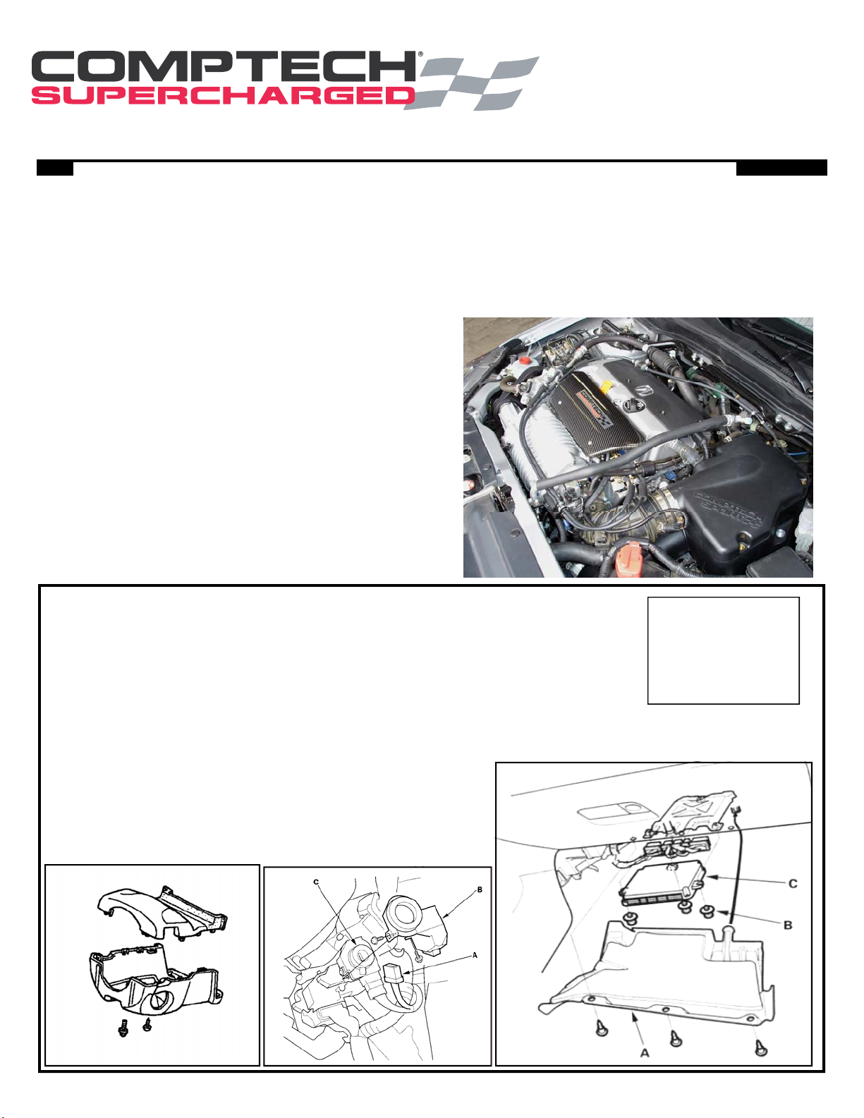
STEP #1 Remove ECU/Immobilizer & Ship to Comptech:
• Disconnect the negative side of the battery.
• Remove the lower dash board cover (A).
• Disconnect the wire plugs at the ECU.
• Remove the three ECU mounting bolts (B) and remove the ECU (C).
• Place the included sticker on the ECU and fill out all of the info.
Immobilizer Removal:
• Remove the steering column covers (2 self tapping screw & 1 washer screw)
• Remove the 2 screws holding the immobilizer control unit-receiver to the ignition key cylinder.
• Disconnect the 7 pin connector (A) and remove the unit (B).
• Send the ECU, immobilizer unit, and your key to HONDATA
using the supplied box (see Address to right).
Ship ECU to:
HONDATA
386 BEECH AVE.
UNIT B2
TORRANCE, CA 90501
1
Page 2
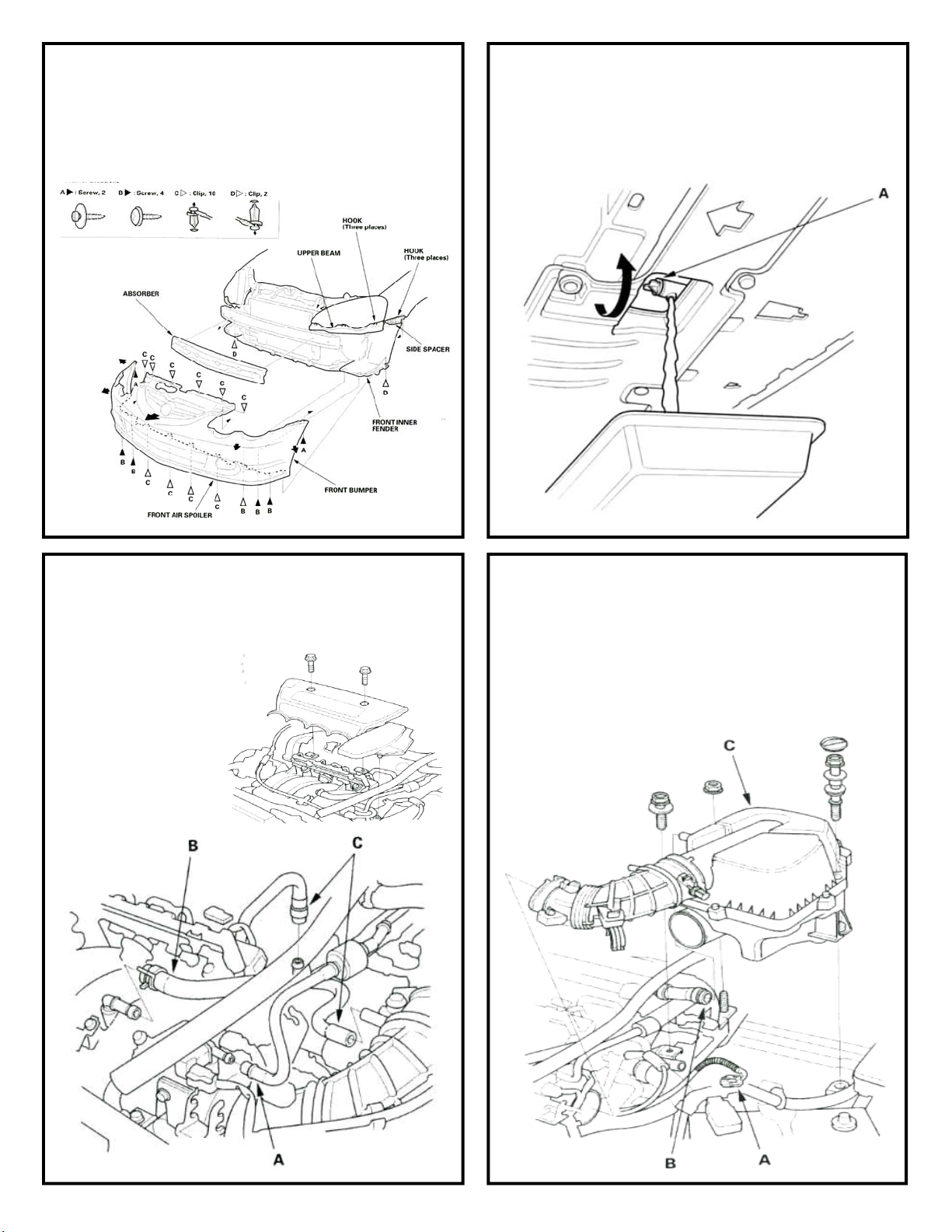
STEP #2 Remove Front Bumper:
• Jack up and support the front of the car using jack
stands.
• Remove the front bumper being careful not to damage
any of hardware because it will be reused.
STEP #3 Prep to remove Manifold:
• Make sure the engine is cool and remove the radiator
cap.
• Drain the cooling system by loosening the drain plug
(A) at the bottom of the radiator.
• Once all of the coolant is drained close the drain plug.
STEP #4 Remove Cover & Disconnect Hoses:
• Remove the intake manifold cover. The cover and
hardware will not be reused.
• Remove the Evaporative Emissions (EVAP) canister
hose (A), brake
booster vacuum
hose (B) and vacuum hoses (C).
Keep all of the
hoses as some will
be reused.
STEP #5 Remove Air Box:
• Disconnect the Intake Air Temperature (IAT) sensor
connector (A), and remove the breather hose (B), then
remove the air cleaner housing (C), and inlet tube.
Keep all of the parts because they will be reinstalled.
2
Page 3

STEP #6 Remove Throttle Body:
• Disconnect the water bypass hoses, then plug the water bypass hoses.
• Disconnect the MAP Sensor, IAC valve connector, TP
sensor, and EVAP canister purge valve connector.
• Remove the (2) M8 nuts and (2) M8 bolts holding the
throttle body to the manifold.
• Leaving the cables attached, carefully move the throttle body out of the way. Making sure not to bend or
kink the cables.
• Use two M8 Flange nuts and remove the Throttle body
studs from the manifold they will be reinstalled into
the new SC manifold.
EVAP Valve
STEP #7 Remove harness:
• Remove the PVC hose (A) but save the clamps because they will be reused.
• Remove the harness holder mounting bolt (B) and harness clamp mounting bolt (C). Remove the harness
holder from the harness it and the hardware will not
be reused.
MAP Sensor
TPS Sensor
STEP #8 Relieve fuel Pressure:
• Loosen the fuel fill cap to relieve any pressure in the
tank.
• Place a wrench on the fuel pulsation damper (A) at
the fuel rail.
• Place a rag (B) over the fuel pulsation damper.
• Slowly loosen it one complete turn
• Once all the fuel is drained retighten the damper.
STEP #9 Remove Fuel Rail:
• Disconnect the fuel line from the rail by squeezing the
lock tabs, push and pull the line until it is loose.
• Remove the harness ground from the manifold and
keep the M6x15 bolt; it will be reused.
• Disconnect the injector harness from each injector and
the harness cover from the rail (B). Trim harness cover
as shown.
• Remove the two M8 nuts holding the rail to the manifold and
remove the rail with injectors
(A). Keep the two rail spacers
and the rail they will be reused.
3
Trim Off Tab
Page 4

STEP #10 Remove Manifold supports:
• From the bottom of the car remove the two
M8 Bolts holding the supports to the manifold.
• Remove the two M8 bolts holding the supports
to the block and remove the supports. They
will not be reused.
STEP #11 Remove Stock Manifold:
• Remove the (2) M8 nuts and (4) M8 flange bolts.
• Use two M8 Nuts and remove the two studs from the cylinder
head (A).
• Remove the intake manifold (B) and gasket. Neither of these
will be reused.
STEP #12 Remove Belt:
• Remove the power steering reservoir from its mounting bracket.
• Move the auto-tensioner (A) to relieve tension from
the belt (B), and remove the belt, it will not be reused.
STEP #13 Remove Power Steering Pump:
• Remove the (2) M8x45 bolts holding the power steering pump to the engine.
• Move the pump out of the way but do not disconnect
the lines
• Save the M8x45 bolts, they will be reused in a
later step.
4
Page 5

STEP #14 Remove the Stock Tensioner:
• Remove the (3) M8 bolts holding the auto tensioner to the
engine and remove the tensioner.
• Remove the tensioner pulley
from the tensioner, the pulley
will be reused.
• The tensioner and the hardware will not be reused.
STEP #15 Remove Alternator:
• Disconnect the power wire (B) (M6 nut), harness connector (A) and the harness bracket (M4 nut) from the
back of the alternator.
• Remove the
M8x105 and
the (2)
M8x45 bolts
from the alternator.
Save the Alternator, it
will be reused, but the
hardware will
not.
Step #16 Remove Radiator overflow bottle:
• Remove the (2) M6x16 washer bolts holding the upper
radiator brackets.
• Remove the (2) M6x25 bolts holding the A/C condenser to the chassis. Pull the radiator and condenser
out and away from the chassis being careful not to
damaged the A/C lines.
• Remove the (2) M6x25 bolts holding the overflow bottle to the fan shroud. Pull the overflow bottle up
through the gap in the radiator and chassis.
• Save all of the parts as they will be reinstalled.
STEP #17 Install Alternator Relocation Brackets:
• For the top bracket remove the M10x105 bolt and reinstall it with the new bracket using the M8x40 allen
bolt supplied in the kit.
• For the bottom bracket use the new (2) M8x20 allen
bolts to mount the new lower bracket.
5
Page 6

Step #18 Reinstall the Alternator:
• Bend the A/C line towards the front of the car by
pushing the line using your hand or a pry bar. Be
very careful not to damage the A/C line.
• Using the new M8x80 and the two new M8x40 flange
bolts supplied in the kit, reinstall the alternator.
• Check to make sure
you have bent the
A/C line enough
(see picture).
STEP #19 Remove the Water outlet:
• Remove the (2) M6x20 water outlet mounting bolts.
• Remove the small rear water line and the larger pas-
senger-side bypass water line. You can leave the
other two waterlines connected. Move the water outlet out of the way.
STEP #20 Move starter cable:
• Remove the harness support bracket as it will not be
reused.
• Move the main
harness to the
passenger side of
the starter.
• Clock the main
starter power
wire down as far
as it will go.
STEP #21 Preinstall Manifold support bracket:
• Loosely mount the lower block to the engine using the
supplied M8x55 flange
bolt.
• Using the supplied
M8x25 flange bolt
loosely mount the drop
link to the lower support.
• Loosely attach the top
mounting block using
the supplied M8x25
flange bolt to the passenger side of the drop
link.
• Leave all the hardware
loose; they will be tightened after the manifold
is installed.
6
Page 7

STEP #22 Main Manifold Installation:
• The blower gets shipped already attached to the main
manifold. Remove the (6) M8x20 bolts holding the
blower plate to the manifold and separate the two.
• Install the main manifold to the cylinder head using
the supplied (5) M8x25 bolts, (2) M8x60 flange bolts,
and heat insulation gasket. Use the supplied Loctite
on the threads of all the bolts. Torque the manifold
bolts to 20 ft-lbs.
• Install the manifold brace to the manifold using the
supplied M8x30 flange bolt. Use Loctite on the threads
going into the manifold.
• Now tighten all of the bolts left loose in Step #22.
STEP #23 Reinstall Water Outlet:
• Reinstall the water outlet removed in step #20.
• Make sure to reconnect the hose, do not forget the
small one on the back.
• Make sure that all of the hose clamps are clocked like
the picture to allow clearance for the throttle cables.
STEP #24 Install P/S Pump Relocation Bracket:
• Using the supplied (3) M8x30 flange bolts, mount the
bracket to the original tensioner mounting points.
STEP #25 P/S pump install:
• Using an air gun and 19mm socket, remove the nut
holding the factory P/S pump pulley. Change the pulley to the new smaller one supplied. Using the air gun
reinstall the nut.
• Mount the pump in place using the M8x45 flange bolt
removed in step #14 on the bottom hole.
• On the top hole use the supplied M8x55 flange bolt
and spacer nut to secure the top of the pump.
• Check to make
sure there is
clearance between the
spacer nut and
the motor
mount stud. If
there is not,
loosen both the
pump bolts,
push the pump
down and retighten.
7
Page 8

STEP #26 Blower Area Preparation:
• Install the new PVC hose (5/16 x 30”) using the stock
clamps removed in step #8. Run the hose out through
the gap between the radiator and chassis for now, it
will be connected in a later step.
STEP #27 Blower Installation:
• Make sure the (6) M8x20 flange bolts are in place before lowering the blower to the main manifold.
• Install the blower on to the main manifold making
sure to line up the roll pins already installed in the
main manifold.
• Start the M8x20
flange bolt under the by-pass
valve first.
• Tighten all 6 of
the blower
mounting plate
flange bolts.
• Install the
blower by-pass
valve vacuum
line.
STEP #28 Install Inlet Manifold:
• Route the fuel injector harness under the end of the
blower on top of the blower mounting plate.
• Using the supplied M8x20 bolts, install the inlet manifold starting with the rear lower bolt first. Also make
sure the injector harness is not pinched between the
inlet manifold and plate.
STEP #29 Install the Blower belt:
• Route the new belt supplied in the kit.
8
Page 9
STEP #30 Pulley Prep:
• Using the stock steel pulley removed in step # 15.
• Press the shorter supplied spacer on the closed side
of the stock pulley.
• Press the longer
supplied spacer into
the open side of the
stock pulley.
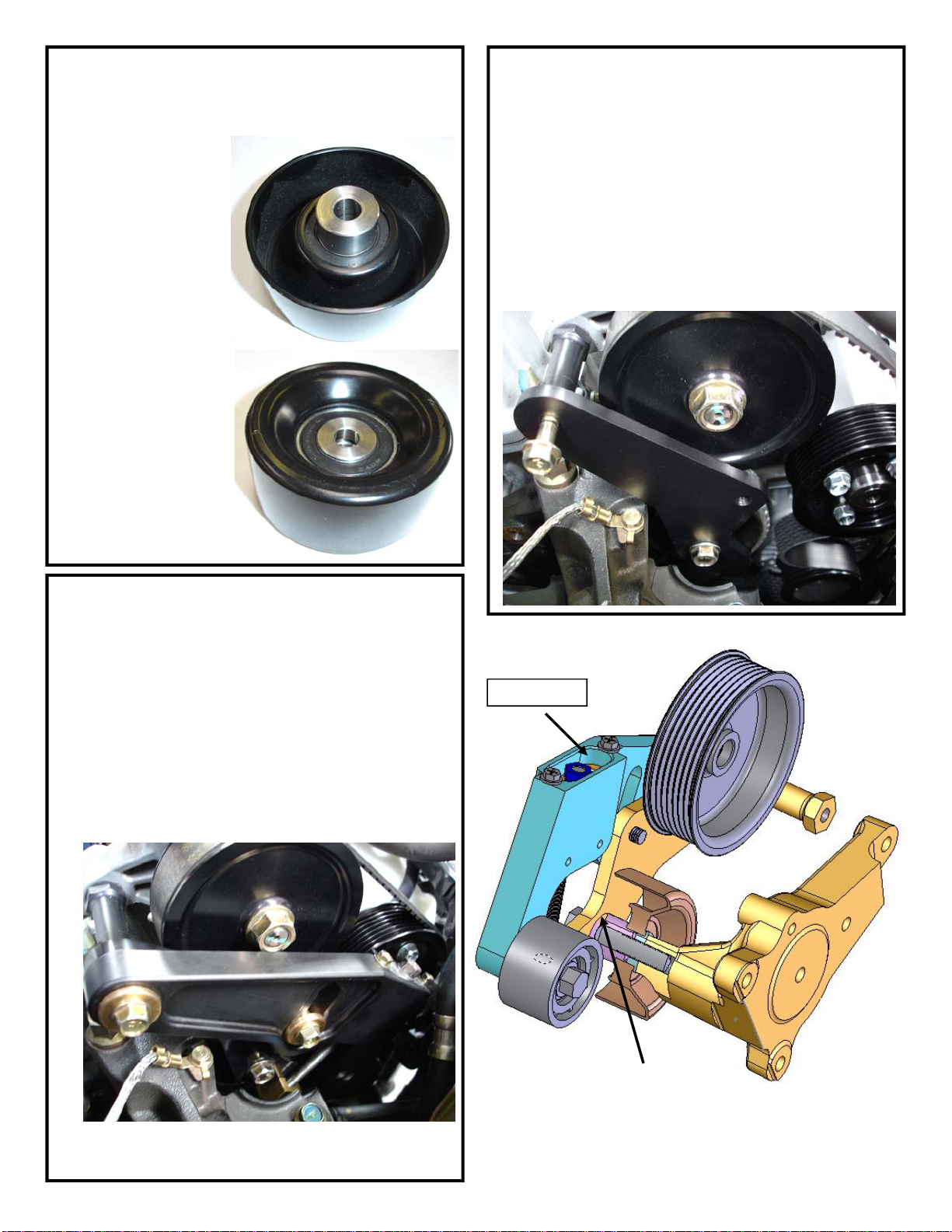
STEP #31 Install Fixed Idler Pulley:
• Using the fixed idle plate and the supplied M10x55
bolt, install the pulley with the longer spacer facing
away from the engine. There is also a small spacer
that needs to go in between the tall spacer and the
idle plate.
• Temporally install the upper M8 flange bolt and torque
the M10 bolt to 31 ft-lbs. Once the M10 bolt is tight
remove the upper M8 flange bolt.
• Make sure the belt runs around the front side of the
pulley.
STEP #32 Install Tensioner:
• Using both the supplied M8x25 bolt with the short
spacer and the M8x45 (removed in step #14) bolt
with the long spacer, mount the tensioner plate making sure that the belt is routed on the back side of the
pulley.
• Make sure that the slot in the brass adjuster foot is
hooked on the edge of the fixed idler pulley plate installed in step #32.
• Once everything is in place, tighten the two M8 bolts
to 16 ft-lbs. Make sure to not over tighten the
bolts.
1/2” Step
9
Insert small spacer here.
Page 10

STEP #33 Setting Belt Tension:
• Tighten the adjusting bolt down until you
have a 1/2” step from the top of the tensioner down to the spring perch. See pic-
ture on page 9.
After about 10 minutes of engine
•
running you will need to reset
the belt tension again.
•
After another 50 miles of driving
you will need to reset the belt
tension again.
• After your 3rd adjustment you should not
have adjust it again.
• But make sure to check it at every oil change.
STEP #34 Relocate P/S Reservoir:
• Remove the P/S bracket from the chassis and using a
letter D drill bit, drill a new hole about .65” over from
the original hole in the bracket.
• Flatten out the location tab so the bracket is flat
across the base.
• Reinstall the bracket to the chassis using the new
hole. Install the P/S reservoir into the bracket. Check
to make sure the reservoir and hoses do not touch
any part of the tensioner or belt.
.65”
STEP #35 Install Spark Plugs:
• Remove the Ignition Coil cover.
• Remove the Coils.
• Remove the stock spark plugs.
• Install the supplied Denso IK24 plugs.
• Reinstall the coils and ignition coil cover.
10
Page 11

STEP #36 Reinstall the Air Bypass Hose:
• Reinstall the original Intake Air Bypass Control Thermal Valve hose using only the clamp on the valve
side.
STEP #37 Fuel Rail Installation Prep:
• Make sure the injector adaptor bushings are pushed all
the way into the manifold. These adaptors make the
Comptech manifold work with the Honda factory fuel
injectors.
• Install the supplied bushings onto each stud along with
the original fuel rail spacers.
STEP #38 Install Fuel Rail:
If this is a Stage 2 upgraded kit install the sup-
•
plied Comptech high flow injectors
• Use a small amount of oil on the fuel injector seal and
reinstall the fuel rail with all of the injectors still in the
rail. Use the supplied spacer nuts to secure the rail to
the manifold.
• Reconnect the fuel supply hose. A small amount of oil
on the end will help.
STEP #39 Install Wiring Harness:
• Reinstall the factory wiring harness cover onto the rail
and reconnect each fuel injector.
• Reinstall the harness ground using the original M6x15
flange bolt.
11
Page 12

STEP #40 Install Throttle Body:
• Install the studs removed in step #6 in to the new
inlet manifold.
• Move the throttle
body back in to
position making
sure that the
throttle cables are
not twisted.
• Reconnect the
Idle Air control
Valve.
• Using the supplied new throttle
body gasket and
original hardware,
mount the throttle body to the
blower inlet manifold.
STEP #41 MAP Sensor Relocation:
• Remove the M5x20 screw holding the MAP sensor in
place. The screw will not be reused.
• Using the MAP sensor spacer block, M5x35 bolt, and
new o-ring supplied in the kit, remount the MAP sensor on to the throttle body.
• Using the supplied
13” vacuum line,
connect the spacer
port to the intake
manifold.
STEP #42 Throttle Body Connections:
• Reinstall the two water lines to the bottom of the
throttle body that were removed in step #7.
• Reconnect the wiring harness connectors back onto
the MAP sensor,
Throttle Position
Sensor and the
EVAP purge
valve connector.
EVAP Valve
MAP Sensor
STEP #43 Reinstall Air Intake Box (C):
• Additional power is available by using a Comptech
IceBox Intake Kit with the supercharger.
• Be sure to reconnect the Inlet Air Temp sensor (A)
and the air tube (B) for the Intake Air Bypass Control
Thermal Valve as seen in step #35.
TPS Sensor
12
Page 13

STEP #44 Reinstall the overflow bottle:
• Insert the bottle between the chassis and the radiator
and remount it
reusing the
stock hardware.
• Reinstall the upper radiator
mounting brackets.
• Remount the A/
C condenser
using the stock
hardware.
• Route the PVC
line above the
overflow bottle
and through the
chassis to the
lower inlet fitting
on the inlet
manifold.
STEP #45 Install Vacuum Lines:
• Reinstall the
factory EVAP
hose. You
may need to
bend the
steel lines
upward to
clear the
throttle cables.
• Install the
supplied
5/16x12”
line for the
brake
booster.
STEP #46 Raise Fuel line pressure:
• Remove the rear lower seat cushion.
• Remove the access panel (A) from the floor. Disconnect the two electrical
connections (B,C) and using a rag to catch the excess fuel disconnect the
fuel line from the fuel tank unit.
• Use the factory Honda tool to remove the top of the pump/sender assembly (we have also found you can also use a larger flat bladed screw driver
as a punch to remove it also).
• Using rags to catch the fuel, slowly pull the pump assembly out of the
tank be very careful not to damage the sending unit float.
• Remove the terminal (A) and the clip (B), remove the regulator.
• Once the regulator is removed disconnect the hose
from the end. Using the supplied tools compress
the regulator in a vice until the tool is bottomed out
(see picture).
• Reinstall the regulator into the pump unit ( a little
oil on the seals will help) in the reverse order as
removal and reinstall everything into the tank.
Make sure to get the top of the unit, clocked correctly in the tank (see picture). Reconnect the electrical connector and fuel line. Reinstall the top
panel and seat.
13
Page 14

STEP #47 Reinstall ECU/Immobilizer & Install ACM:
• Reinstall the immobilizer unit & reinstall the steering column panels. (see step #1)
• Remount the ECU in the reverse order of removal. Plug in connectors (C,D & E only).
• Install the ACM in between the factory wiring harness and the ECU (connectors A &B), using the supplied jumper har-
ness. Tuck the ACM box up on top of the ECU.
• Once everything is installed reconnect negative side of the battery.
STEP #48 Refill Cooling System/Install Bumper:
• Refill the cooling system using a mixture of 50% antifreeze and 50% water.
• Fill the radiator to the base of the filler neck.
• Loosely install the radiator cap and proceed to
step#49.
• Reinstall the front bumper see step #2.
STEP #49 Starting the Car:
• Turn the ignition key on and off a few times to run the
fuel pump and build fuel pressure.
• Check for any fuel or coolant leaks.
• If everything checks out OK, start the car.
• Once the car is running let it idle until the cooling fans
come on at least twice. Make sure all of the air is bled
out of the cooling system.
• Shut the engine off. Check the coolant level in the
radiator. Top it up if necessary and install the radiator
cap tightly.
• Install the supplied Emissions Information sticker to
the bottom side of the hood next to the stock emissions
sticker.
14
Page 15
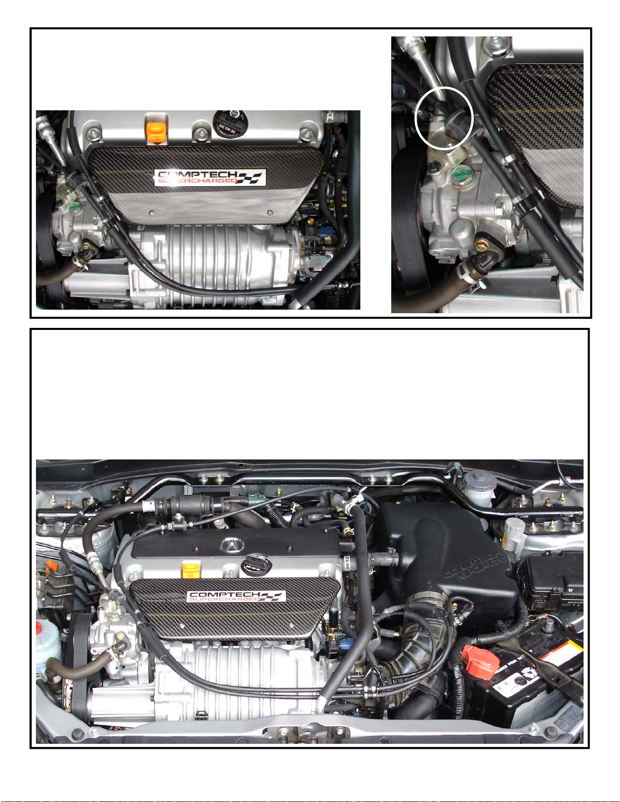
STEP #50 Install Fuel Rail Cover:
• Using the supplied M6x10 Button head allen bolts install the Comptech
Carbon Fiber fuel rail cover.
• Remove the throttle cable routing bracket off of the P/S pump. Use the
supplied 4” ty-rap to hold the cables to the P/S line.
STEP #51 Drive the car :
• Always use the Highest Octane fuel available.
• Check your engine oil level on a regular basis.
• Check your belt tension.
• If you have any questions please call (888)-626-6783 between the hours of 8:00 AM and 5:00 PM Pacific Standard
time.
• Please put a copy of these installation instructions in the car for your customer.
• To further improve the performance of your Comptech Supercharger kit we recommend the use of a Comptech Ice-
box, Header and Cat-Back exhaust system.
• Enjoy.
Comptech® 4717 GOLDEN FOOTHILL BLVD • EL DORADO HILLS, CA 95762 • 916.933.1080 • FAX 916.939 .9196 • www.comptechusa.com •
15
Page 16

Comptech® Product Warranty
Comptech - All products manufactured by Comptech are warranted against defects in materials and workmanship for
a period of three years from date of original purchase. This warranty is applicable only to parts which were
purchased on or following January 1, 2006. All parts purchased on or preceding December 31, 2005 are
subject to the conditions of our previous warranty period of two years. This warranty applies only to the
original retail purchaser and is not transferable. This warranty is intended to cover Comptech products when they are
used in the manner for which they were originally designed. This limited warranty shall be void on all products found to
have been used in racing or off-road applications, of any nature whatsoever, and on all products that show evidence of
abuse, lack of maintenance, improper installation, misapplication, alteration in any way whatsoever from their original
design or negligence in the use of Comptech products by the original retail purchaser or by any agent of the original
purchaser. The warranty specifically excludes, but is not limited to; brake pad material, brake rotors, clutch friction surfaces, belts, normal maintenance items, and those items designated as a racing part. This warranty applies only to
products made by Comptech, and does not include claims for labor or inconvenience. This warranty does not cover
consequential damages claimed as a result of the failure or use of a Comptech product. Other products distributed by
Comptech are covered by the terms of that manufacturer's warranty. Comptech reserves the right to change product
design and/or specification without prior notice.
Warranty Service Procedure - In the event a problem develops with a Comptech product, please contact Comptech at
916.933.1080 during our normal business hours (8 AM to 5 PM M-F PST).
1. It may be determined that the product will have to be returned to Comptech for warranty inspection. A Return
Goods Authorization will be assigned to you and is required for return, unless specified otherwise by a Comptech employee.
2. The retailer or the customer should return the product in question, freight prepaid. It must be accompanied by the
original sales receipt and a clear description of the problem.
3. If the product is determined to be defective and within the warranty period, Comptech will repair, replace or issue a
credit to the customer at Comptech's discretion. Any repaired or replaced product will be returned to sender, freight
prepaid via UPS or truck.
4. No replacement warranty parts will be shipped until original parts are returned to Comptech for inspection.
Returns - In the event that a purchase must be returned, please contact a Comptech salesperson for a Return Goods
Authorization number.
1. All returns must have the RGA number clearly written on shipping label or box, or shipment may be refused.
2. No returns after 14 days.
3. A 20% restocking fee will be assessed on all merchandise returned in 100% resalable condition (clean packaging, all
pieces intact, etc.). If returned goods are not 100% resalable, an additional charge will be assessed. If mer chandise is
damaged, or shows signs of installation, the return will be disallow ed.
4. All returns must be freight prepaid.
5. Special Orders parts are not returnable.
6. All approved returns are for credit only.
Comptech®
4717 Golden Foothill Parkway
El Dorado Hills, CA 95762
Phone : 916.933.1080
Fax: 916.939.9196
16
 Loading...