

Page 1
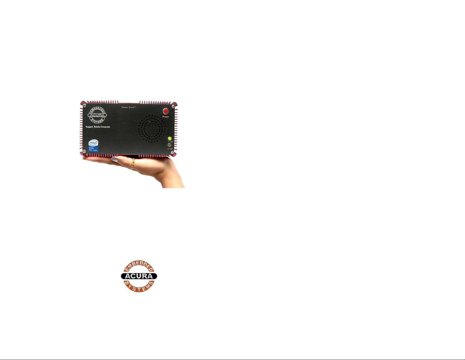
PowerBrick-CV
User’s Manual
Edition 3.1
Copyright
The material in this document is the intellectual property
of Acura Embedded Systems Inc. This publication,
including all photographs, illustrations and software, is
protected under international copyright laws, with all
rights reserved. Neither this manual, nor any of the
material contained herein, may be reproduced without
written consent of Acura Embedded Systems Inc.
Version 3.1
Warranty
The PowerBrick-CV system is protected by a limited
warranty for a period of three (3) years.
Trademark Recognition
Microsoft, MS-DOS and Windows are registered
trademarks of Microsoft Corp.
Preface
Mobile Data Computer
Withsssssss
Digital Video Recorder
IBM PC is a registered trademark of International
Business Machines Corporation.
Intel, MMX, Pentium, Pentium-II, Pentium-III, Pentium-4,
Celeron are registered trademarks of Intel Corporation.
AWARD is a registered trademark of AWARD
International Inc.
Other product names used in this manual are the
properties of their respective owners and are
acknowledged.
Page 2

PowerBrick-CV User’s Manual
Disclaimer
Acura Embedded Systems Inc. takes every care in the pr eparati on
of this document, but no guarantee is given as to the correctness
of its contents. Our products are under continual improvement and
we reserve the right to make changes without notice. The
manufacturer makes no representations or warranties with respect
to the contents hereof and specifically disclaim any implied
warranties of merchantability or fitness for any particular purpose.
The manufacturer reserves the right to revise this publication an d
to make changes from time to time in the content hereof without
obligation of the manufacturer to notify any person of such revision
or changes.
In general, the manufacturer will not be liable for loss of data
or other direct, indirect, special, incidental or consequential
damages arising from the use or inability to use the product
or documentation, even if advised of the possibility of such
damages.
Table of Content
1. OVERVIEW…..…………………………………………… 1
2. INSTALLATION…………………………………………… 2
2.1 CONTENTS OF THE COMPUTER BOX………………. 2
2.2 CONNECTING CABLES AND GETTING STARTED…. 2
2.3 MOUNTING IN YOUR VEHICLE OR FINAL LOCATION. 4
2.4 MOUNTING TOOLS………………………………………. 4
3 TECHNICAL INFORMATION……………………………. 5
3.1 BIOS SETUP ……………………………………………… 5
3.2 OPERATING SYSTEMS………………………………….. 6
3.3 OPERATING SYSTEM RESTORE PROCESS ……….. 6
3.4 WINDOWS XP EMBEDDED, PROFESSIONAL ……… 6
3.5 APPLICATION SOFTWARE…………………………….. 6
3.6 SPECIFICATIONS FOR POWER BRICK-CV. ……….. 7
3.7 OPERATION AND MAINTENANCE…………………….. 8
3.8 WARMING………………………………………………….. 8
3.9 POWER BRICK- CV WIRING DIAGRAM………………. 9
4 CONTACT INFORMATION………………………………. 10
Page 3
PowerBrick-CV User’s Manual
1. Overview
The PowerBrick-CV is a combined rugged industrial high performance
computer and a 4-channel digital video recorder in the same chassis. The
system is designed to work in industrial and marine mobile environments,
where reliability and endurance with respect to vibration, shock, humidity
and temperature are of essence. The PowerBrick-CV system architecture
is modular which allows for easy upgrading and expandi ng.
For public safety providers, the PowerBrick-CV system offers outstanding
computing power while at the same time acting as a tool for
incident/evidentiary documentation, surveillance and training. Typical
areas of application include:
• Mobile surveillance, border patrolling, marine patrolling
• Law enforcement vessels and vehicles
• Patrol boats and vehicles
• Fire emergency vehicles
• Public transportation security
• Seaport surveillance/security
The main features are:
• Core Duo processor
• Intel 945GM Chipset
• 4-channel camera input, 120 fps
• Multi-screen video monitoring, allows simultaneous play-
back of all channels
• 2.5” hard drive
• 1GB DDR2 RAM
• On-board 10/100/1000 LAN, USB 2.0
• Standard Audio jacks
• 1 x PCMCIA card bus slot
• 1 x Compact Flash –II slot
• GPS/AVL options
• 10-30 Volt DC input
• Dimensions: 7.60” x 4.35” x 8.15” (W x L x H)
For installation, mounting and cable connections, please see th e next
Section. Technical information is available in Section 2.
Page 1
2. Installation
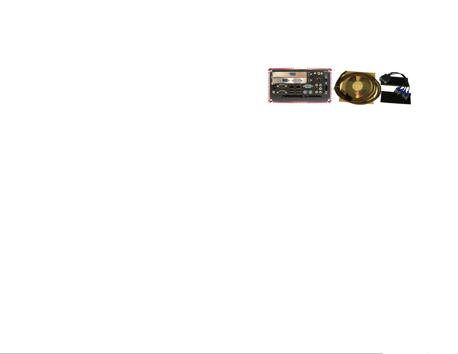
2.1 Contents of the Computer Box
Figure2.1: Box major components
In the box you will find the following items: PowerBrick-CV
computer, power plug, mounting with rubber suspension, camera
cable.
If you have purchased Windows operating system with your
computer, the CD should be included. Keep it in a safe place.
Please see your separate monitor packaging for installation and
other information for the touch screen monitor.
Do not turn power on until you have read the next section and
all cables are connected.
2.2 Connecting Cables and Getting Started
In order to get familiar with your system before mounting it at your
vehicle (or final location), we suggest you look at the c onnec tions on
both ends of the computer such as shown in Figs. 2.2 and 2.3,
connect up the unit, and place it into operation.
Page 2
Page 4

PowerBrick-CV User’s Manual
N
A
t
Ethernet port
S/PDIF out
USB port
Figure2.3: Back side of PowerBrick-CV.
After connecting all applicable cables it is safe to power-on the system.
(Warning: use either DC from the dedicated power supply or AC, never
both at the same time!).
2.3 . Mounting in your vehicle or final location
This chapter provides you with the information of fixed system mounting.
Prior to that, please prepare the installation tools and appro priate items. If
you are not clear about the items, contact your dealer for information.
2.4 . Mounting tools
For mounting your computer in a vehicle you need the following tools:
• Screw driver
• Drill
Page 4
Main Power
Ignition control
VGA port
udio ou
DC I
Compact flash II
Mouse
Keyboard
Power Button
Figure2.2: Front side of PowerBrick-CV.
Connect all applicable cables such as:
• Keyboard
• Mouse
• Monitor
• Power supply cable
Optional device cables or units that yo u provide yours elf could include the
following:
• USB cable
• Speaker and microphone cables
• RJ45 Ethernet TP cable
• Serial port cable
Page 3
RS-232 COM port3
Camera Input
RS-232 COM port1
RS-232 COM port4
Page 5

PowerBrick-CV User’s Manual
3. Technical Information
3.1 BIOS Setup
The PowerBrick-CV uses the Phoenix TrustedCore BIOS which based on
the Intel® Core™ Duo, Core 2 Duo, Celeron™ M processors and Intel
mobile 945GM Express and ICH7-M chipsets. With high performance and
integrated audio and video capabilities. And also it is designed for
extended environmental temperature operation up to 70ºC, so it is ideal for
use in space-constrained systems and high-temperature environments.
The system BIOS performs a Power On Self Test (POST) upon power on
or reset. If problems are encountered during POST, the following may
occur:
A warning message is displayed on the primary display device
but the boot process continues.
The system is halted when a terminal (fatal) POST error occurs.
Before shutting down the system, however, the error handler will
attempt to communicate the cause of the error condition, by
writing the error to port 80h, sounding a beep code, and listing
the error code on the display.
After POST completes, the system BIOS will search for boot devices in
the order configured by the BIOS setup utility and load the operating
system from the first boot device found. To activate BIOS setup program,
press <F2>key immediately after you turn on the system. Table 3.1 is the
BIOS setup utility menu map.
3.2 Operating Systems
The PowerBrick-CV will generally be provided with a preinstalled
operating system such as Windows XP Professional or Embedded. To
restore the operating system, follow the procedure outlined in 3.4. You can
also use an external CD-ROM drive to change, reinstall or repair the
operating system through a USB 2.0 port.
3.3. Operating System Restore Process
1. Back up your existing drive C:\ files.
2. Restart the computer.
3. Hold down the F8 key to enter Windows Advanced Boot Menu
options.
4. Select “Return to OS Choices” and press “Enter”.
5. Select “Quick Restore Option”, press “Enter” and follow the
instructions.
6. After re-boot, click on “Touch screen” in the “Restore drivers and
software” window and follow the instructions.
3.4 Windows XP Embedded
If you want to reinstall Windows XP Embedded, boot the computer, place
the CD-ROM labeled “Windows XP Embedded Recovery” into the exter nal
Table 3.1: BIOS setup utility menu map
Page 5
CD-ROM drive, press RESET and follow the instructions on the screen.
We recommend that this be done by experienced computer users only.
3.5 Application Software
You should be able to run all normal/generic application software such a s
Microsoft Word, Excel, PowerPoint, Adobe software etc. if you have
Windows installed. See the relevant manual/help guides for the specific
software. Acura is not responsible for failure of any software on your
computer but if you have any particular software needs please call Acura
Technical Support or
e-mail
support@acuraembedded.com.
Page 6
Page 6

PowerBrick-CV User’s Manual
R
3.6 Specifications for PowerBrick-CV Table 3.2: System Features
Processor Intel® Core™ Duo supports Hyper Threading
Technology; VRM 10.0 standard
Chipset Intel 945GM
System FSB 533/667MHz Front Side Bus
Memory Dual channel DDR2 SDRAM at 400/533/667MHz
Video Intel Graphics Media Accelerator 950 integrated
400MHz RAMDAC graphics 256MB
Audio Audio jacks
Hard Disk Two SATA ports (1.5Gbs/s) for hard disks
DVR Module 4-port 120 FPS camera input
640 x 480, 640 x 240, 320 x 240 image resolution
3.7 Operation and maintenance
This module requires no routine maintenance. The green LED indicator
when lit indicates proper operation and health.
The power supply must be protected by a 15A auto fuse on the input line
from the vehicle battery.
3.8 Warning
Before power up the computer, make sure all cables connected to the
computer and the monitor.
WARNING:
Fist hookup all cables then turn on computer power
swich.Make sure monitor power led on or blinking.
Standard Motion - JPEG compression
Multi-screen monitoring
LAN 10/100/1000 Mb Fast Ethernet
USB 2.0 Integrated 4 independent OHCI controller supporting
USB 1.1 ports; Integrated 1 EHCI controller
supporting USB 2.0 ports; Dynamic connection
support to USB 2.0 or USB 1.1 devices
Hardware
Monitor
Power
Management
Dimensions
Power 10 – 30 Volt
System, processor temperature, voltage and fan
speed monitor. Auto Thermal fan speed control
ACPI 3.0 supporting states S0, S3, S4, S5, and C0,
C1, C2, C3, C4
7.60“ x 4.35“x 8.15“
TO COMPUTE
TO MONITOR
Table 3.3: Input/Output
15 Pin VGA 1
TV out 1
S/PDIF OUT 1
PS/2 / Keyboard 1
PS/2 Mouse 1
Audio jacks 1
USB 2.0 4
RJ45 Fast Ethernet 2
RS232 COM port 2 Option 3
12 V DC Power Jack 1
Page 7
page 8
Page 7

PowerBrick-CV User’s Manual
3.9 Power Brick- CV Wiring Diagram
Ignition Controller (Optional)
4.Contact Information
With the unique set of products, Acura Embedded Systems remains
committed to its goal of providing trouble-free and customer-friendly
service. A special customer service unit has been set up specifically to
cater to our esteemed customers' needs.
Technical Support:
• Phone: 1-866-502-9666
• Email:
Mail address:
Acura Embedded Systems Inc.
Unit #1, 7711-128th Street
Surrey, BC V3W 4E6
CANADA
Ph: (604) 502-9666 Fax: (604) 502-9668
support@acuraembedded.com
page 9
page 10
Page 8

PowerBrick-CV User’s Manual
Toll Free 1.866.502.9666
www.acuraembedded.com
 Loading...