

Page 1

ACURA EMBEDDED SYSTEMS INC.
Rugged Panel PC
AcuPanel 19
User Manual
Revision 1.3
Acura Embedded Systems Inc.
Published January 29 2013
Disclaimer ............................................................................................... iii
Regulatory Compliance Statements.........................................................iii
Declaration of Conformity....................................................................... .iii
Safety Information .................................................................................. iii
Installation Recommendations................................................................ iv
Safety Precautions...................................................................................iv
Ordering Information ...............................................................................iv
Technical Support and Assistance ..........................................................v
Conventions Used in this Manual ........................................................... v
Package Contents ...................................................................................v
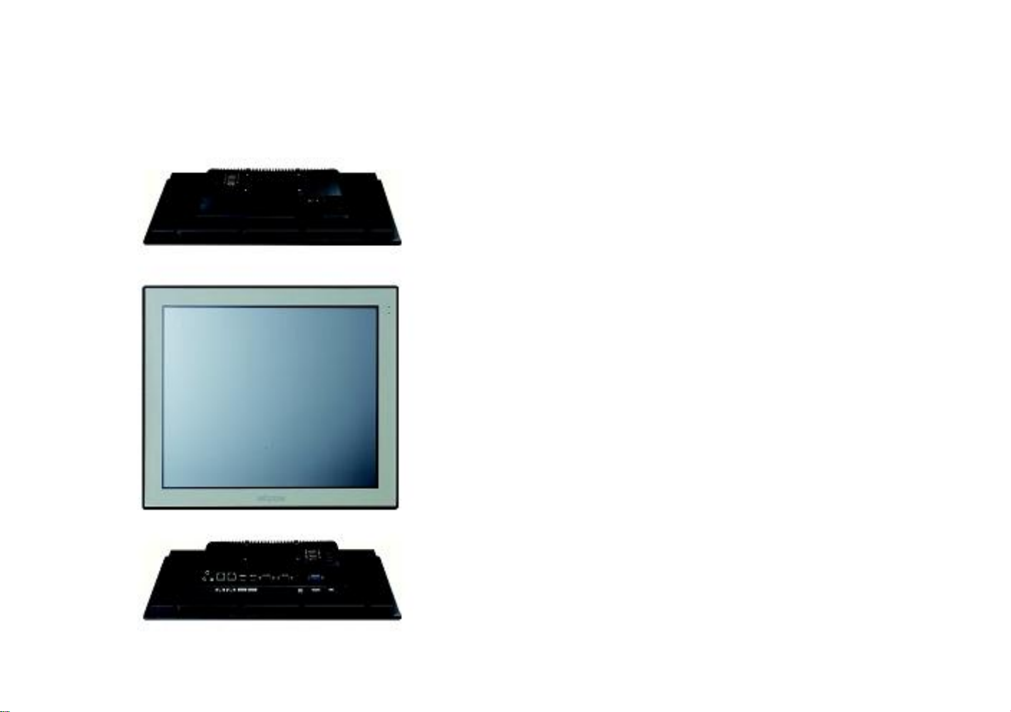
Chapter 1: Product Introduction
AcuPanel 19 Overview.......................................................................... 1
Specifications........................................................................................ 1
Knowing Your AcuPanel 19................................................................... 3
Rear Top............................................................................................ 3
Rear Bottom ...................................................................................... 4
Rear …………………………………………… .................................... 5
Mechanical Dimensions......................................................................... 6
Chapter 2: Jumpers and Connectors
Before You Begin .................................................................................. 7
Precautions .......................................................................................... 7
Jumper Settings .................................................................................... 7
Locations of the Jumpers and Connectors ............................................8
Top View ........................................................................................... 8
Bottom View ..................................................................................... 9
Jumpers and DIP Switch Settings..........................................................10
CMOS Clear Select .......................................................................... 10
AT/ATX Selection ..............................................................................10
Dimming Type Select .........................................................................11
Dimming Signal Level Select ............................................................ 11
Panel Resolution Select .................................................................... 12
LCD Panel VDD Power Select ...........................................................13
Contents
Preface
Content
Page 2

Content
Touch 4/5 Wire Select...........................................................................13
COM3 RI Pin Power Select ................................................................. 14
COM4 RI Pin Power Select ................................................................. 14
Connector Pin Definitions ........................................................................15
External I/O Interface ...........................................................................15
12V-30V DC Power Input .................................................................15
VGA Port ..........................................................................................15
Line-out Jack.....................................................................................15
PS/2 Keyboard/Mouse Port .............................................................16
COM2 Port: Serial Port RS232/422/485 ..........................................16
COM1 Port: Serial Port RS232/422/485 ..........................................16
COM3 Port and Connector: Serial Port RS232 ................................17
COM4 Port and Connector: Serial Port RS232 ................................18
USB Ports .........................................................................................19
LAN2 Port .........................................................................................20
LAN1 Port .........................................................................................20
Internal Connectors...............................................................................21
LVDS Channel 1 ..............................................................................21
LVDS Channel 2 ..............................................................................21
Panel Backlight Connector ..............................................................22
Touch Sensor Connector .................................................................22
USB Connector ................................................................................23
Bluetooth Connector.........................................................................23
SATA Connector...............................................................................24
SATA DOM Power Connector .............................................................24
Line-in/Mic-in Connector ......................................................................25
Speaker-out Connector........................................................................25
GPIO Connector ..................................................................................26
DIO Connector .....................................................................................27
Power/HDD LED Indicator Connector ..................................................28
Backlight Control Input Connector .......................................................29
Dimming Control Button Connector .......................................................29
SIM Card Slot..................................................................................29
Mini-PCIe Slot .................................................................................30
Mini-PCIe Slot .................................................................................31
CFast Card Slot ..............................................................................32
Power Button Connector.................................................................32
Block Diagram ........................................................................................33
ii
Chapter 3: System Setup
Installing a SATA Hard Drive ................................................................34
Installing a CFast Card ..........................................................................36
Installing a SODIMM ..............................................................................38
Installing a SATA DOM ..........................................................................40
Installing a Mini PCIe Module.................................................................44
Installing the Half-Size Mini PCIe Module ..........................................46
Installing the Full-Size Mini PCIe Module ...........................................47
Installing a Bluetooth Module .................................................................51
Placing Panel Mount Hole Blocks...........................................................55
Installing the Power Adapter Bracket......................................................56
Plugging the DC Power Cable ...............................................................59
Panel Mounting ......................................................................................60
Chapter 4: BIOS Setup
About BIOS Setup .................................................................................61
GPIO When to Configure the BIOS.......................................................61
Default Configuration ............................................................................61
Entering Setup ......................................................................................62
Legends.................................................................................................63
BIOS Setup Utility..................................................................................63
Main ..................................................................................................63
Advanced ..........................................................................................64
Chipset...............................................................................................71
Boot....................................................................................................74
Security .............................................................................................76
Save & Exit ........................................................................................76
Appendix A: GPI/O Programming Guide................................78
Appendix B: Digital I/O Programming Guide.........................79
Appendix C: Watchdog Programming Guide........................81
Appendix D: Power Consumption..........................................83
Appendix E: Troubleshooting.................................................84
Page 3

Preface
Preface
Disclaimer
The information in this document is subject to change without prior notice and
does not represent commitment from Acura Embedded Systems Inc. However,
users may update their knowledge of any product in use by constantly checking
its manual posted on our website: http://www.acuraembedded.com. Acura
Embedded Systems Inc shall not be liable for direct, indirect, special, incidental,
or consequential damages arising out of the use of any product, nor for any
infringements upon the rights of third parties, which may result from such use.
Any implied warranties of merchantability or fitness for any particular purpose is
also disclaimed.
Regulatory Compliance Statements
This section provides the FCC compliance statement for Class B devices and
describes how to keep the system CE compliant.
Declaration of Conformity
FCC
This equipment has been tested and verified to comply with the limits for a
Class B digital device, pursuant to Part 15 of FCC Rules. These limits are
designed to provide reasonable protection against harmful interference when the
equipment is operated in a commercial environment. This equipment
generates, uses, and can radiate radio frequency energy and, if not installed and
used in accordance with the instructions, may cause harmful interference to radio
communications. Operation of this equipment in a residential area (domestic
environment) is likely to cause harmful interference, in which case the user
will be required to correct the interference (take adequate measures) at their
own expense.
CE
The product(s) described in this manual complies with all applicable
European Union (CE) directives if it has a CE marking. For computer systems to
remain CE compliant, only CE-compliant parts may be used. Maintaining
CE compliance also requires proper cable and cabling techniques.
Safety Information
Before installing and using the device, note the following precautions:
▪ Read all instructions carefully.
▪ Do not place the unit on an unstable surface, cart, or stand.
▪ Follow all warnings and cautions in this manual.
▪ When replacing parts, ensure that your service technician uses parts
specified by the manufacturer.
▪ Avoid using the system near water, in direct sunlight, or near a heating
device.
▪ The load of the system unit does not solely rely for support from the
rack mounts located on the sides. Firm support from the bottom is highly
necessary in order to provide balance stability.
▪ The computer is provided with a battery-powered real-time clock circuit. There is
a danger of explosion if battery is incorrectly replaced. Replace only with the
same or equivalent type recommended by the manufacturer. Discard used
batteries according to the manufacturer's instructions.
iii
Page 4

Preface
Installation Recommendations
Ensure you have a stable, clean working environment. Dust and dirt can get
into components and cause a malfunction. Use containers to keep small
components separated. Adequate lighting and proper tools can prevent
you from accidentally damaging the internal components. Most of the
procedures that follow require only a few simple tools, including the following:
▪ A Philips screwdriver
▪ A flat-tipped screwdriver
▪ A grounding strap
▪ An anti-static pad
Usingyourfingerscandisconnectmostoftheconnections.Itisrecommended
that you do not use needle-nose pliers to disconnect connections as these
can damage the soft metal or plastic parts of the connectors.
Safety Precautions
1. Read these safety instructions carefully.
2. Keep this User Manual for later reference.
3. Disconnect this equipment from any AC outlet before cleaning. Use a
damp cloth. Do not use liquid or spray detergents for cleaning.
4. For plug-in equipment, the power outlet socket must be located near the
equipment and must be easily accessible.
5. Keep this equipment away from humidity.
6. Put this equipment on a stable surface during installation. Dropping it or
letting it fall may cause damage.
7. The openings on the enclosure are for air convection to protect the
equipment from overheating. DO NOT COVER THE OPENINGS.
8. Make sure the voltage of the power source is correct before connecting the
equipment to the power outlet.
9. Place the power cord in a way so that people will not step on it. Do not
place anything on top of the power cord. Use a power cord that has been
approved for use with the product and that it matches the voltage
and current marked on the product's electrical range label. The
voltage and current rating of the cord must be greater than the
voltage and current rating marked on the product.
10. All cautions and warnings on the equipment should be noted.
11. If the equipment is not used for a long time, disconnect it from the power
source to avoid damage by transient overvoltage.
12. Never pour any liquid into an opening. This may cause fire or electrical shock.
13. Never open the equipment. For safety reasons, the equipment should be
opened only by qualified service personnel.
14. If one of the following situations arises, get the equipment checked by service
personnel:
a. The power cord or plug is damaged.
b. Liquid has penetrated into the equipment.
c. The equipment has been exposed to moisture.
d. The equipment does not work well, or you cannot get it to work
according to the user's manual.
e. The equipment has been dropped and damaged.
f. The equipment has obvious signs of breakage.
15. Do not place heavy objects on the equipment.
16. The unit uses a three-wire ground cable which is equipped with a third pin to
ground the unit and prevent electric shock. Do not defeat the
purpose of this pin. If your outlet does not support this kind of plug,
contact your electrician to replace your obsolete outlet.
17. CAUTION: DANGER OF EXPLOSION IF BATTERY IS INCORRECTLY
REPLACED. REPLACE ONLY WITH THE SAME OR EQUIVALENT TYPE
RECOMMENDED BY THE MANUFACTURER. DISCARD USED BATTERIES
ACCORDING TO THE MANUFACTURER'S INSTRUCTIONS.
Ordering Information
The following information below provides ordering information .
• Barebone
AcuPanel 19
- 19" SXGA LED Backlight Touch Panel PC, Intel® Atom™ D2550
1.86 GHz, touch screen, 4GB DDR3, 2x RS232/422/485 and 4/4 DI/O
with isolated protection, 2x RS232, 2x2 GPI/O, Brightness adjustment
buttons
• Optional
12V, 60W AC/DC power adapter w/o power cord
iv
Page 5
Technical Support and Assistance
1. For the most updated information of Acura Embedded Systems Inc’s products,
visit Acura Embedded Systems Inc.'s website at www.acuraembedded.com.
Acura Embedded Systems Inc. Address:
Suit #1,7711 128th Street, Surrey,BC. V3W 4E6 Canada
Ph: 604-502-9666 Fax: 604-502-9668
Toll Free: 1-866-502-9666
2. For technical issues that require contacting our technical support team or
sales representative, please have the following information ready
before calling:
- Product name and serial number
- Detailed information of the peripheral devices
- Detailed information of the installed software (operating system,
version, application software, etc.)
- A complete description of the problem
- The exact wordings of the error messages
Warning!
1. Handling the unit: carry the unit with both hands and handle it with care.
2. Maintenance: to keep the unit clean, use only approved cleaning products
or clean with a dry cloth.
3. Compact Flash: Turn off the unit's power before inserting or removing a
Compact Flash storage card.
Conventions Used in this Manual
Warning: Information about certain situations, which if not observed, can cause
personal injury. This will prevent injury to yourself when performing a
task. TIO
N!
Caution: Information to avoid damaging components or losing data.
Driver CD
DC Power Cable
v
Flat Head Screw
Preface
Touch Pen
Panel Mount Hole Block
PS/2 Y Cable
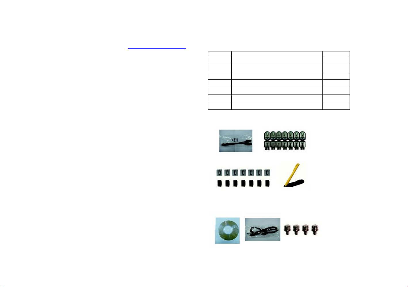
Package Contents
Before continuing, verify that the package you received is complete. Your package
should have all the items listed in the table.
Item
Description
Qty
1
PS/2 Y Cable
1
2
Panel Mount Kit
14
3
Driver CD
1
4
Touch Pen
1
5
DC Power Cable
1
6
Flat Head for HDD Installation
4 7 Panel Mount Hole Block
14
Panel Mount Kit
Touch Pen
Flat Head Screw
Driver CD
CD Power Cable
PS/2Y Cable
Panel Mount Hide Block
Page 6
Chapter 1: Product Introduction
Chapter 1: Product Introduction
AcuPanel19 Overview
Key Features
▪ 4:3 19" SXGA Fanless LED Panel Computer
▪ Intel® Atom™ D2550, Dual Core, Low Consumption CPU
▪ Flush Panel by 5-wire Touch Screen
▪ Dual GbE/ 2nd display-VGA/ Line-in/ Line-out/ Mic-in/ PS2 KB/MS
▪ USB x4/ 2x mini-PCIe sockets/ 1x CFast/ 2x RS232/ 422/ 485
▪ Optional 3.5G / Wi-Fi Module / 2.5"HDD / 2x COMs / GPIO / DIO
▪ DDR3 1GB / 2.5" HDD Bracket
▪ IP65 Compliant Front Panel
▪ Mounting Support: Panel/ Wall/ Stand/ VESA 100mm x 100mm
▪ Wide Range Power Input 12V~ 30V DC
Specifications
Panel
▪ LED Size: 19", 4:3
▪ Resolution: SXGA 1280x1024
▪ Luminance: 350cd/m2
▪ Contrast ratio: 1000
▪ LCD color: 16.7M
▪ Viewing Angle: 80(U), 80(D), 85(L), 85(R)
▪ Backlight: LED
Touch Screen
▪ 5-wire resistive (flush panel type)
▪ Light transmission: 81%
▪ Interface: USB
System
▪ CPU: On-board Intel® Atom™ Dual Core processor D2550, 1.86GHz,
1M L2 Cache
▪ BIOS: AMI BIOS
▪ System chipset: Intel® NM10 Express chipset
1
Page 7

▪ System memory: 2x 204-pin DDR3 SO-DIMM socket, 1G DDR3 (Default),
support up to 4GB DDR3-800/1066, Non-ECC and un-buffered
▪ Storage Device:
- 1x external locked CFast socket
- 1x hard drive bay: optional 1x 2.5" SATA HDD or 1x SATA DOM
▪ Watchdog timer: Watchdog timeout can be programmed by
software from 1 second to 255 seconds and from 1 minute to 255
minutes (Tolerance 15% under room temperature 25°C)
▪ H/W status monitor: Monitoring system temperature, and voltage
▪ Expansion: 2x mini-PCIe sockets
(support optional WiFi or 3.5G module)
▪ Panel backlight control button: Increase brightness / decrease
brightness / Backlight On/Off
Rear I/O
▪ Ethernet: 2x RJ45
▪ 2nd display VGA port: 1x DB15
▪ Audio port: 1x Line out; 1x Line in; 1x MIC-in
▪ USB: 4x USB 2.0
▪ PS2 keyboard/ mouse
▪ Power switch
▪ Reset button
▪ COM #1: RS232/422/485 w/RI or 5V selection
▪ COM #2: RS232/422/485 w/RI or 12V selection
▪ DIO w/ 2.5kv isolated:
4x Digital Input (Source type)
- Input Voltage (Dry Contact): Logic 0: Close to GND
- Logic 1: Open
- Input Voltage: Logic 0: 3V max
- Logic 1: +5V ~ +30V
4x Digital Output (Sink type)
- Output Voltage: 3.6V ~ 5V
- Sink current: 200 mA max. per channel
▪ GPIO: 2x digital in/ 2x digital out
▪ COM #1: RS232/422/485 w/ 2.5kv isolated
▪ COM #2: RS232/422/485 w/ 2.5kv isolated
▪ COM #3: RS232 w/ RI or 5V selection
▪ COM #4: RS232 w/ RI or 12V selection
Audio
▪ AC97 codec: Realtek ALC886-GR
▪ Audio interface: Line out/Line in/MIC-in Audio Jack
Ethernet
▪ LAN chip: dual Intel® 82574L Gigabit LAN
▪ Ethernet interface: 10/100/1000 Based-Tx Ethernet compatible
Mechanical & Environment
▪ Color: pantone black\RAL 15 00 front bezel w/ Pantone 400C\RAL
090 80 10 metal style membrane
▪ IP protection: IP65 front
▪ Mounting: panel/ wall/ stand/ VESA 100mm x 100mm
▪ Power input: 12V~ 30V DC
▪ Power adapter: Optional AC to DC power adaptor (+12V, 60W)
▪ Vibration:
- IEC 68 2-64 (w/ HDD)
- 1Grms @ sine, 5~500Hz, 1hr/axis (HDD Operating)
- 2Grms @ sine, 5~500Hz, 1hr/axis (CFast Operating)
- 2.2Grms @ random condition, 5~500Hz, 0.5hr/axis (Nonoperating)
▪ Shock:
- IEC 68 2-27
- HDD: 20G@wall mount, half sine, 11ms
▪ Operating temperature: -5°C to 50°C
▪ Storage temperature: -20°C to 75°C
▪ Operating humidity: 10%~90% relative humidity, non-condensing
Limits to be at 90% RH at max 50°C
▪ Dimension: 457.64 x 379.24 x 61.25 mm
▪ Weight: 6.5 Kg
Certifications
▪ CE approval
▪ FCC Class A
Chapter 1: Product Introduction
2
Page 8
Chapter 1: Product Introduction
Knowing Your AcuPanel 19
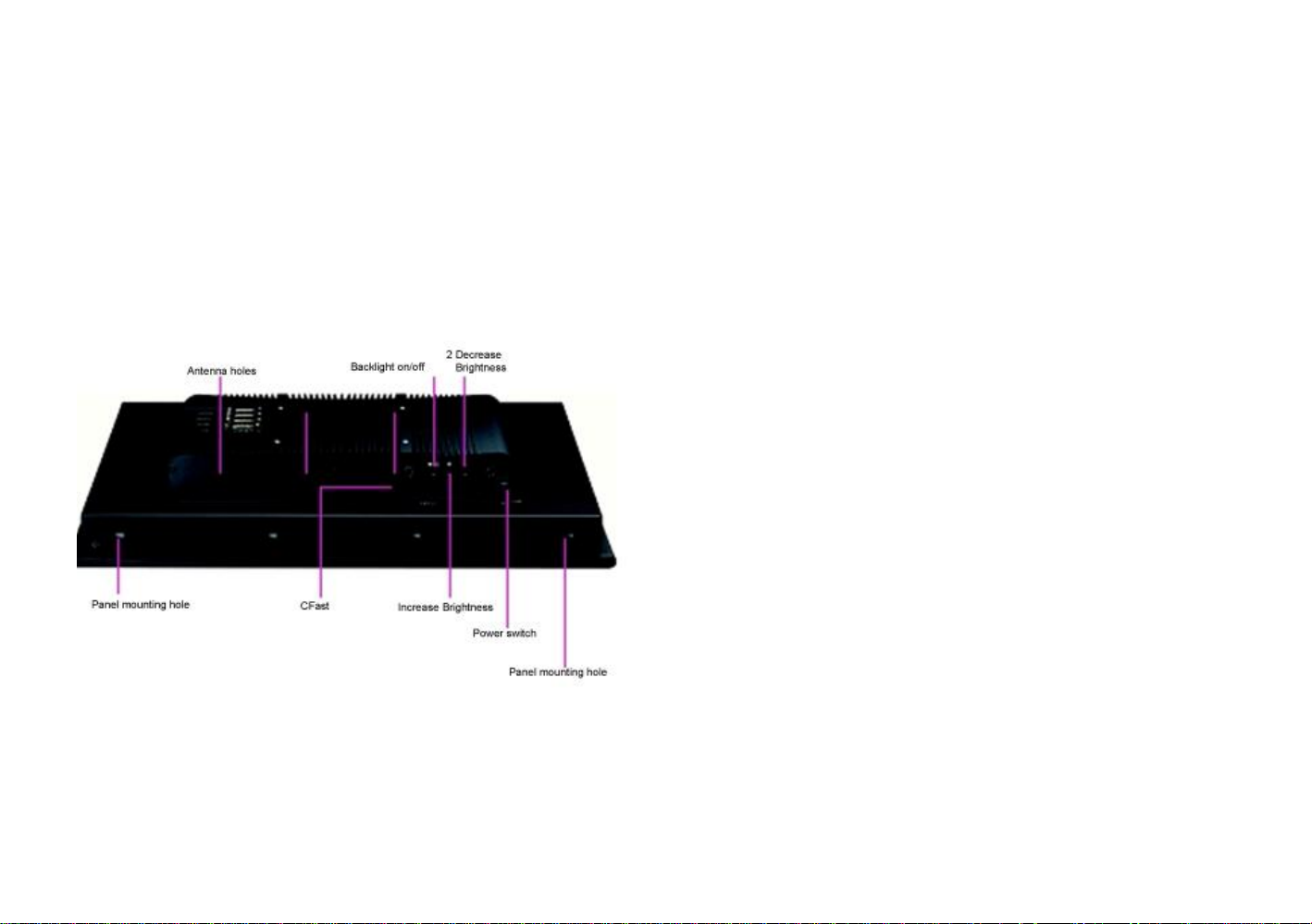
Rear Top
Antenna holes for optional 3.5G/ WiFi/ Bluetooth
The 3 external antenna holes are used to mount and connect optional 3.5G/
WiFi/ Bluetooth antennas.
CFast Card Socket
Used to insert a CFast card.
Power Switch
Press to power-on or power-off the panel PC.
Panel Backlight Control Buttons
Backlight On/Off
Press to turn-on or turn-off the display
Increase Brightness
Press to increase brightness of the screen.
Decrease Brightness
Press to decrease brightness of the screen.
8 brightness level available:
30%, 40%, 50%, 60%, 70%, 80%, 90% and 100%
3
Page 9
Chapter 1: Product Introduction
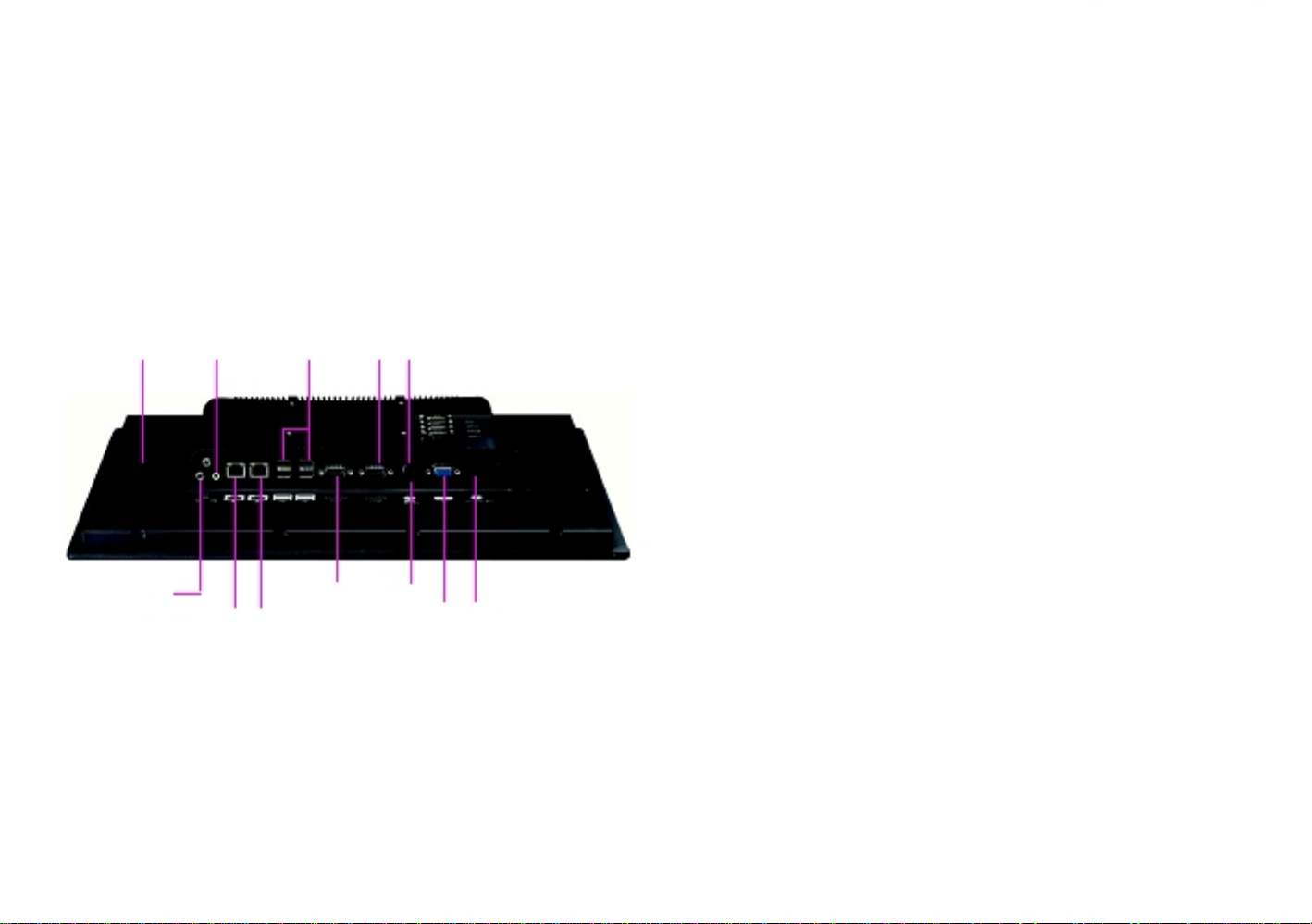
Rear Bottom
Line-in
Line-out
USB
COM 2 PS/2 KB/MS
Mic-in
COM 1
Reset
LAN 1
LAN 2
VGA
12V-30V
DC Input
Line-in
Used to connect an audio device as sound source.
Mic-in
Used to connect an external microphone.
Line-out
Used to connect a headphone or a speaker.
LAN 1 and LAN 2
Used to connect the system to a local area network. LAN1 supports Wake
up on LAN.
USB
Used to connect USB 2.0/1.1 devices.
COM 1 and COM 2
These COM ports support RS232/422/485 compatible series device by BIOS
setting.
AcuPanel 19 has 2.5kV isolated protection.
PS/2 KB/MS
Used to connect a PS/2 keyboard and a PS/2 mouse
Reset Button
Press this button to restart the system.
VGA
Used to connect an analog VGA monitor.
12V-30V DC Input
Used to plug a DC power cord.
4
Page 10
Chapter 1: Product Introduction
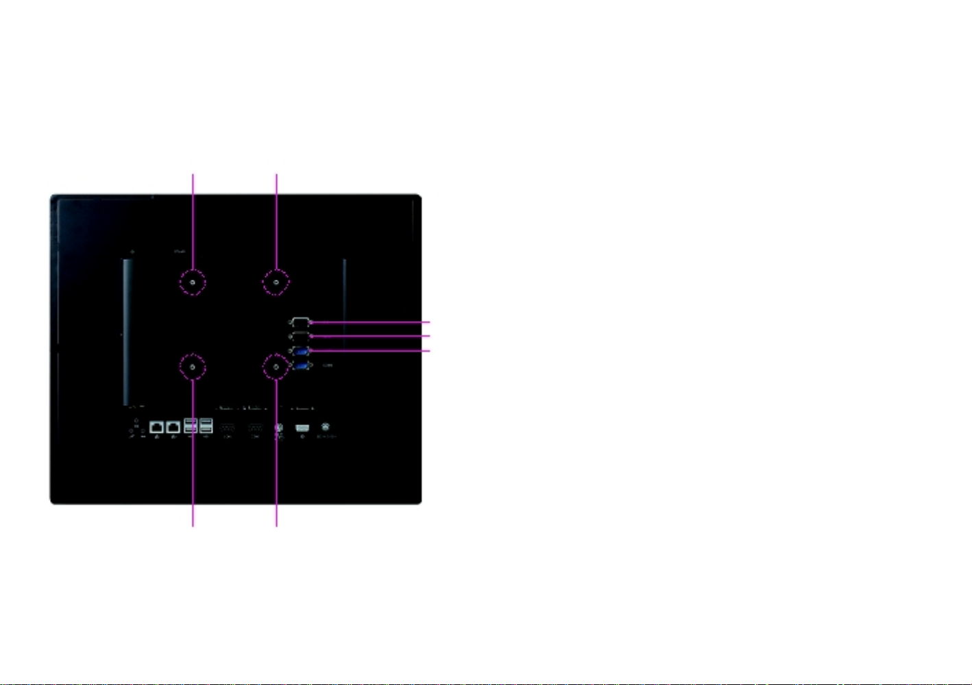
Rear (AcuPanel19)
VESA Mounting Hole
VESA Mounting Hole
DIO
GPIO
COM3
COM4
VESA Mounting Hole
VESA Mounting Hole
DIO
The digital I/O connector support 4 isolated protection digital input channels
and 4 isolated protection digital output channels.
Isolation voltage: 2500 VDC
DI:
4x Digital Input (Source Type)
- Input Voltage (Dry Contact)
Logic 0: Close to GND
Logic 1: Open
- Input Voltage (Wet Contact)
Logic 0: 3V max.
Logic 1: +5V-+30VDC
4x Digital Output (Sink Type)
- Output Voltage: Typical 24VDC, 30VDC max.
Logic 0: 0-0.6VDC
Logic 1: 3.6-5VDC
- Sink Current: 200mA max. per channel
GPIO
The GPIO connector supports 2 digital input and 2 digital output.
COM3 and COM4
These COM ports support RS232 compatible serial devices.
COM3 supports 5V or RI by Jumper setting.
COM4 supports 12V or RI by Jumper setting.
VESA Mounting Holes
These are mounting holes for VESA mount (100x100mm).
5
Page 11
Chapter 1: Product Introduction
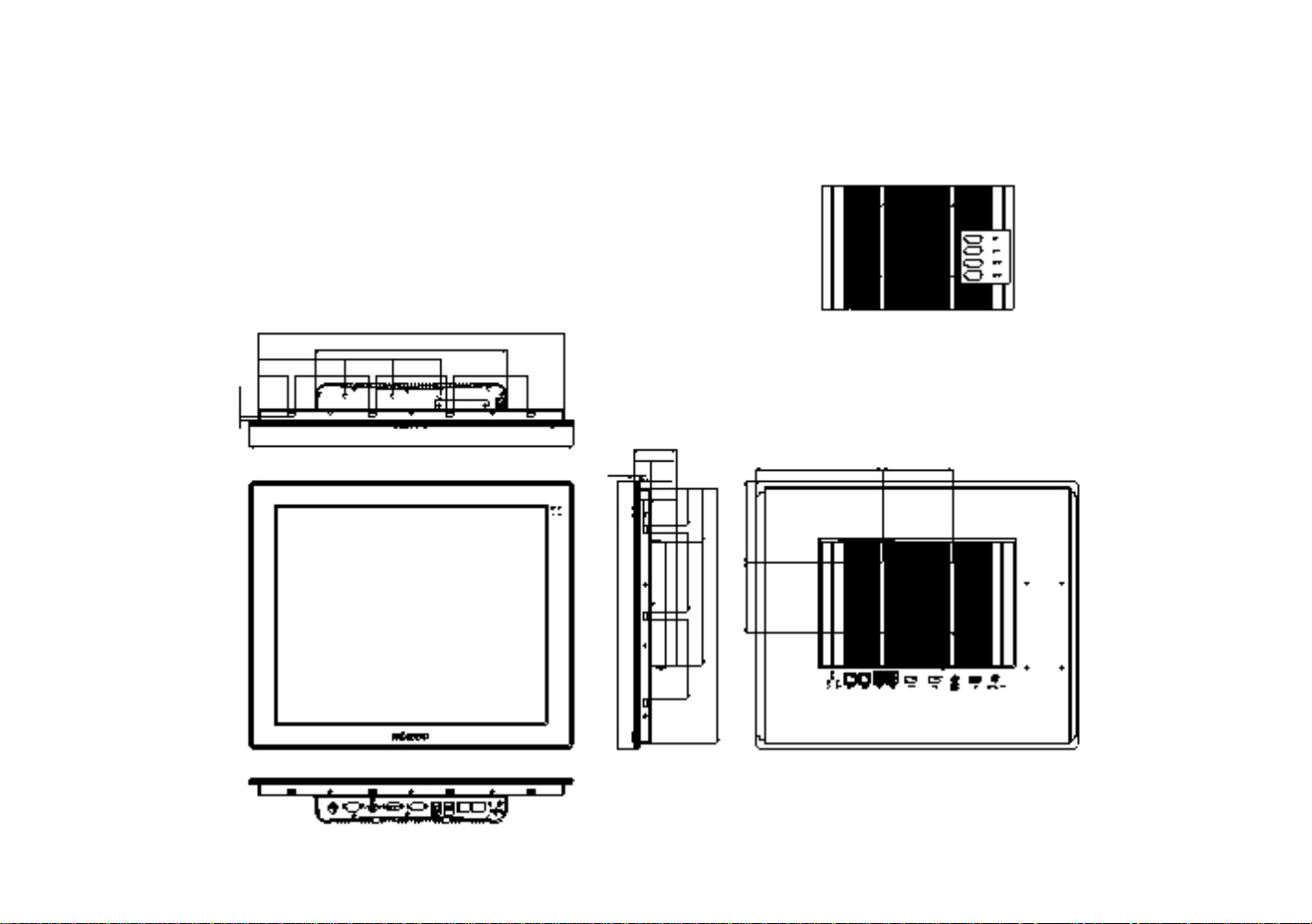
Mechanical Dimensions
AcuPanel19
121.32
41.49
67.22
104.50
431.34
270.36
67.23
97.35
104.50
457.64
8.10
61.25
24.25
16.15
10.15
179.30
100
6
6.90
52.90
Page 12

Chapter 2: Jumpers and Connectors
Chapter 2: Jumpers and Connectors
This chapter describes how to set the jumpers and connectors on the
motherboard. Note that information in this chapter applies to AcuPanel19.
Before You Begin
▪ Ensure you have a stable, clean working environment. Dust and dirt can
get into components and cause a malfunction. Use containers to keep
small components separated.
▪ Adequate lighting and proper tools can prevent you from accidentally
damaging the internal components. Most of the procedures that follow
require only a few simple tools, including the following:
- A Philips screwdriver
- A flat-tipped screwdriver
- A set of jewelers screwdrivers
- A grounding strap
- An anti-static pad
▪ Using your fingers can disconnect most of the connections. It is
recommended that you do not use needle-nosed pliers to disconnect
connections as these can damage the soft metal or plastic parts of the
connectors.
▪ Before working on internal components, make sure that the power is off.
Ground yourself before touching any internal components, by touching
a metal object. Static electricity can damage many of the electronic
components. Humid environments tend to have less static electricity than
dry environments. A grounding strap is warranted whenever danger of
static electricity exists.
Precautions
Computer components and electronic circuit boards can be damaged by
discharges of static electricity. Working on computers that are still connected
to a power supply can be extremely dangerous.
Follow the guidelines below to avoid damage to your computer or yourself:
▪ Always disconnect the unit from the power outlet whenever you are
working inside the case.
▪ If possible, wear a grounded wrist strap when you are working inside the
computer case. Alternatively, discharge any static electricity by touching
the bare metal chassis of the unit case, or the bare metal body of any
other grounded appliance.
▪ Hold electronic circuit boards by the edges only. Do not touch the
components on the board unless it is necessary to do so. Don't flex or
stress the circuit board.
▪ Leave all components inside the static-proof packaging that they shipped
with until they are ready for installation. Use correct screws and do not
over tighten screws.
Jumper Settings
A jumper is the simplest kind of electric switch. It consists of two metal
pins and a cap. When setting the jumpers, ensure that the jumper caps are
placed on the correct pins. When the jumper cap is placed on both pins, the
jumper is short. If you remove the jumper cap, or place the jumper cap on
just one pin, the jumper is open.
Refer to the illustrations below for examples of what the 2-pin and 3-pin
jumpers look like when they are short (on) and open (off).
Two-Pin Jumpers: Open (Left) and Short (below)
7
Three-Pin Jumpers: Pins 1 and 2 are Short
Page 13
Chapter 2: Jumpers and Connectors
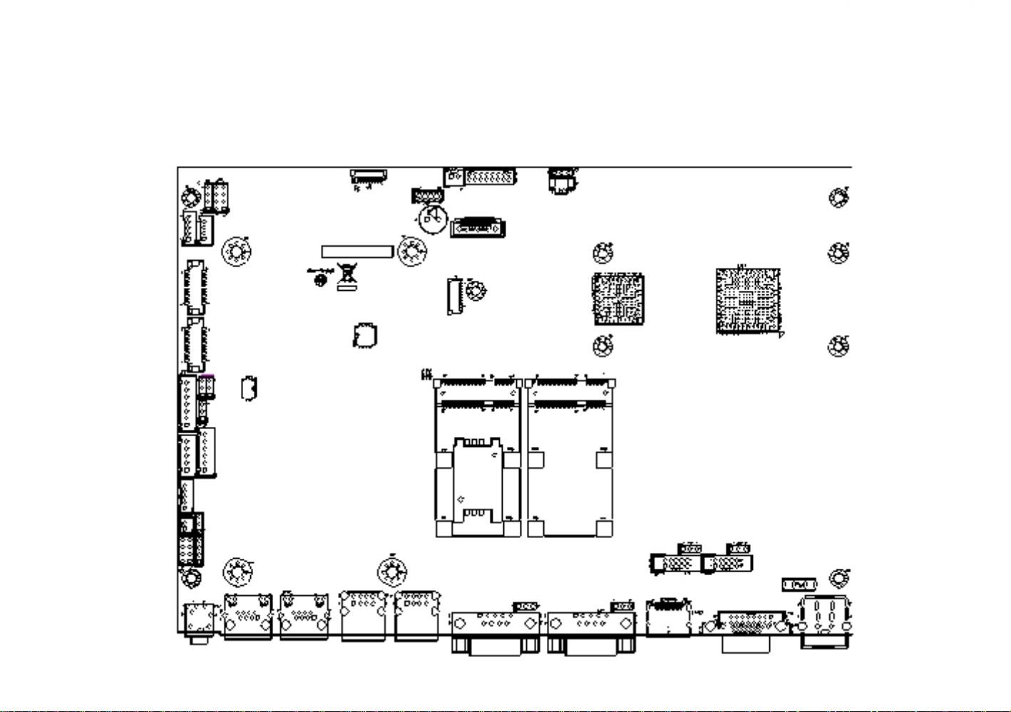
Locations of the Jumpers and Connectors
Top View
CN2
JP4
JP2
J2
JP1
J4
J5
CN3
CN4
J6
CN5
SW1
J7
JP5
JP6
JP7
CN6
CN7
SW2
J9
J8
CN8
J10
J11
JP8
JP9
JP10
JP11
J12
CN9
CN10
LAN1
LAN2
USB1
USB2
JP12
JP13
CN13
CN14
CN15
CN16
VGA1
8
Page 14
Chapter 2: Jumpers and Connectors
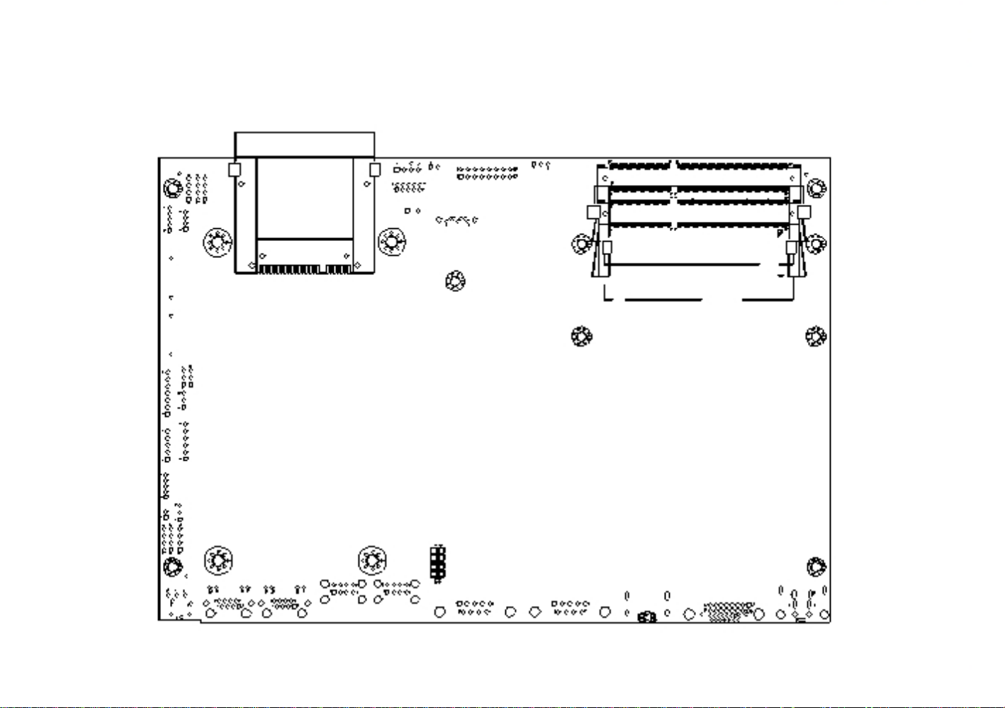
Bottom View
DDR3 SODIMM
DIMM1
DIMM2
CFast card socket
9
Page 15
Chapter 2: Jumpers and Connectors
Jumpers and DIP Switch Settings
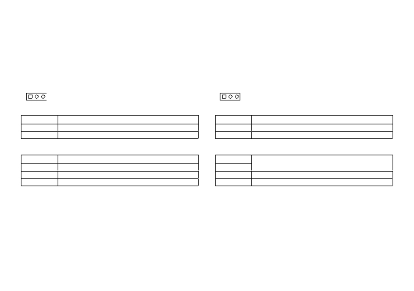
CMOS Clear Select
Connector type: 1x3 3-pin header, 2.54mm pitch
Connector location: JP1
1
3
AT/ATX Selection
Connector type: 1x3 3-pin header, 2.54mm pitch
Connector location: JP8
1
3
Pin
1-2 On
2-3 On
1-2 On: default
Pin
1
2
3
Settings
Normal
Clear BIOS
Pin
1-2 On
2-3 On
2-3 On: default
Pin
1
2
3
Settings
AT Mode
ATX Mode
Definition
NC
RTC Power
GND
Definition
AUTO (AT MODE)
PWRBT In
Manual ( ATX MODE)
10
Page 16
Chapter 2: Jumpers and Connectors
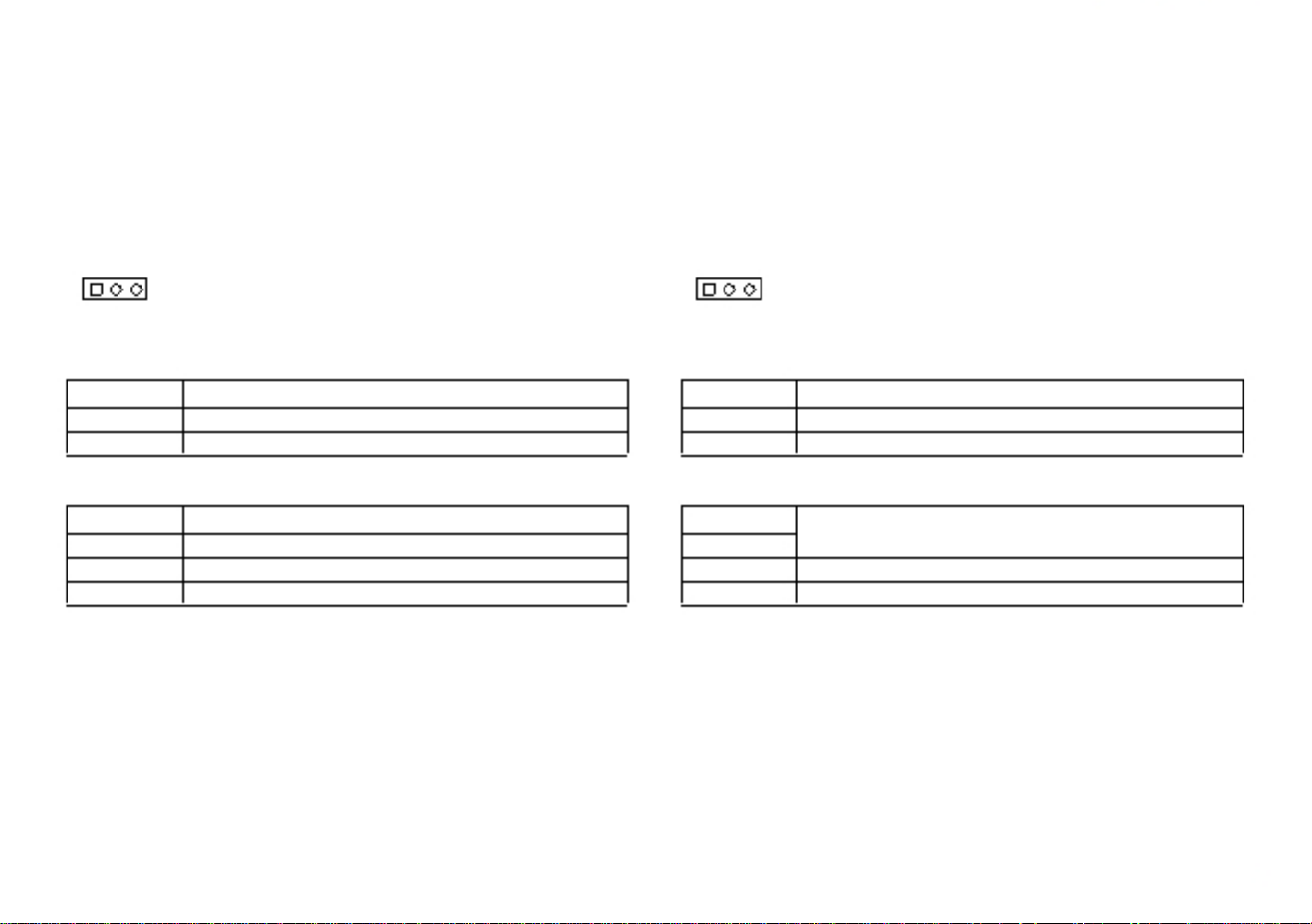
Dimming Type Select
Connector type: 1x3 3-pin header, 2.54mm pitch
Connector location: SW2
Dimming Signal Level Select
Connector type: 1x3 3-pin header, 2.54mm pitch
Connector location: JP6
1
3
SW2-1
SW2-2
Settings
On
Off
PWM Mode
Off
Default: PWM
On
Analog Mode
Model
AcuPanel 19
Pin
Settings
1-2 On
3.3V
Model
AcuPanel 19
Definition
VCC3
Power for Dimming
VCC5
Pin
1
2
3
11
N
O
1
2
Page 17
Chapter 2: Jumpers and Connectors
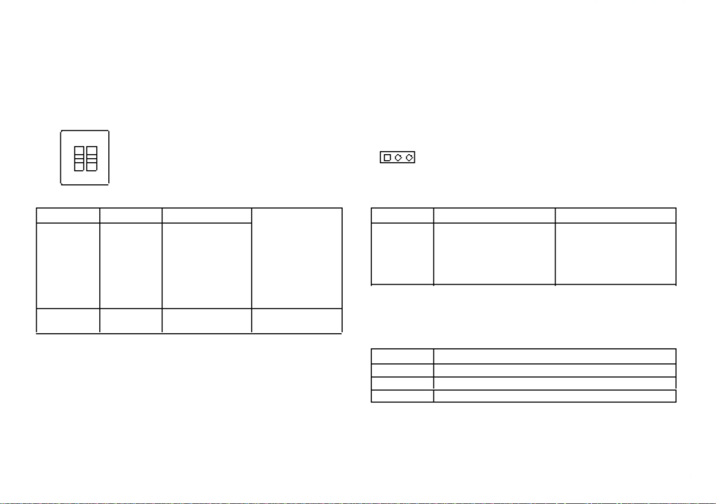
Panel Resolution Select
Connector type: 4-pin On/Off Switch
Connector location: SW1
SW1-1
ON
SW1-2
ON
SW1-3
ON
SW1-4 Resolution/Color/Backlight On
ON
800 x 600/6 bits/High
OFF
ON
ON
OFF
OFF
OFF
ON
OFF
OFF
ON
ON
OFF
1280 x 1024/8 bits/Low
1280 x 1024/8 bits/High
1920 x 1080/8 bits/High
Model
AcuPanel 19
12
N
O
3
4
1
2
Page 18

Chapter 2: Jumpers and Connectors
LCD Panel VDD Power Select
Connector type: 1x3 3-pin header, 2.54mm pitch
Connector location: JP5
Touch 4/5 Wire Select
Connector type: 1x3 3-pin header, 2.54mm pitch
Connector location: JP7
1
3
1
3
Pin
Settings
1-2 On
3.3V
2-3 On
5V
Model
AcuPanel 19
Pin
1-2 On
2-3 On
1-2 On: default
Settings
5 wire
4 wire
1-2 On: default
Pin
1
2
3
Definition
VCC3
Power for VDD
VCC5
13
Page 19
Chapter 2: Jumpers and Connectors
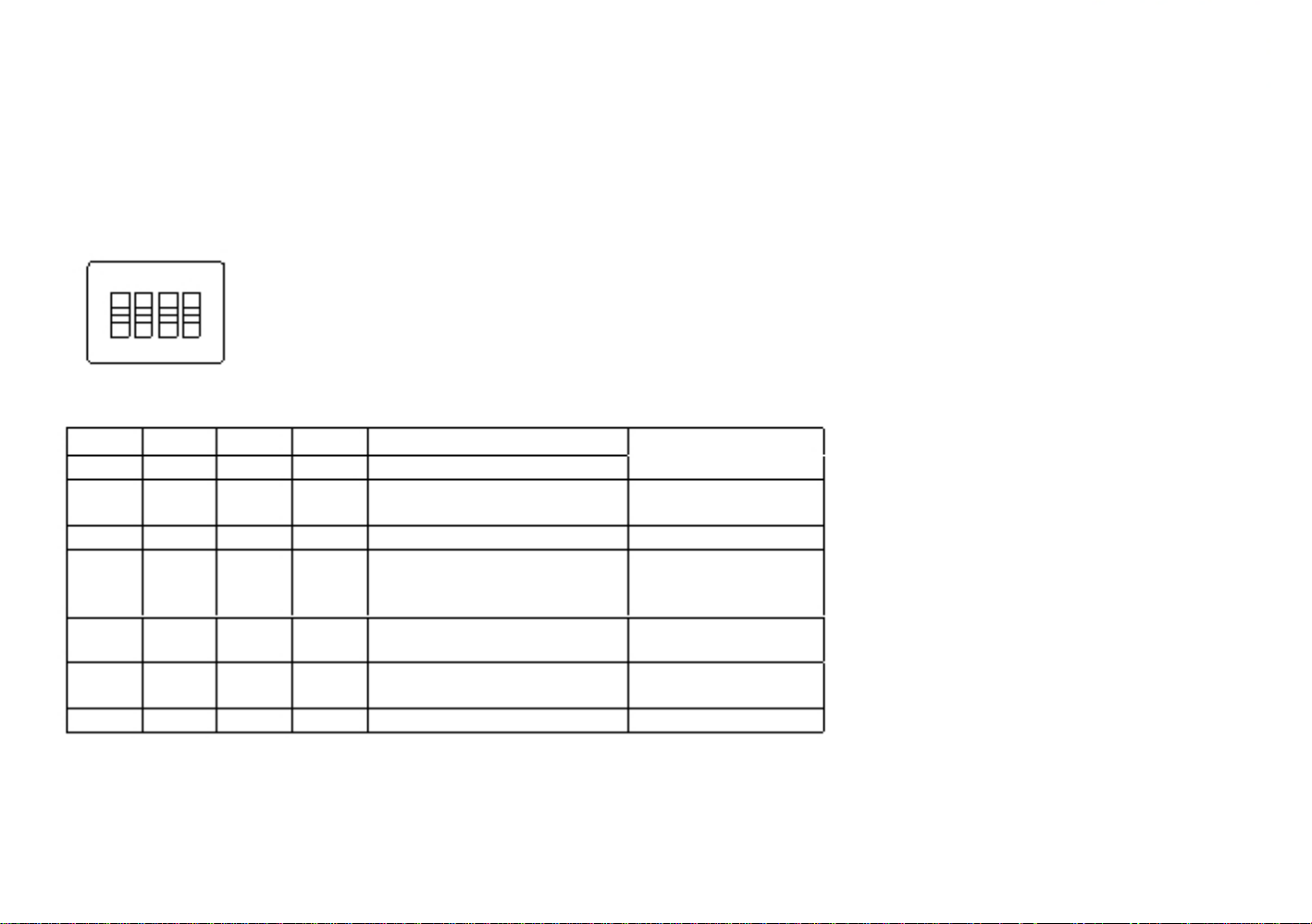
COM3 RI Pin Power Select
Connector type: 1x3 3-pin header, 2.54mm pitch
Connector location: JP9
COM4 RI Pin Power Select
Connector type: 1x3 3-pin header, 2.54mm pitch
Connector location: JP10
1
3
1
3
Pin
1-2 On
2-3 On
1-2 On: default
Pin
1
2
3
Settings
RING
+5V
Pin
1-2 On
2-3 On
1-2 On: default
Pin
1
2
3
Settings
RING
+12V
Definition
SP3_RI
SP3_PSRI
VCC5
Definition
SP4_RI
SP4_PSRI
12V
14
Page 20
Chapter 2: Jumpers and Connectors
Connector Pin Definitions
External I/O Interface
12V-30V DC Power Input
Connector type: DC 4-pin DIN power jack with shield
Connector location: CN13
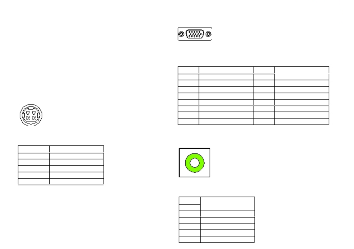
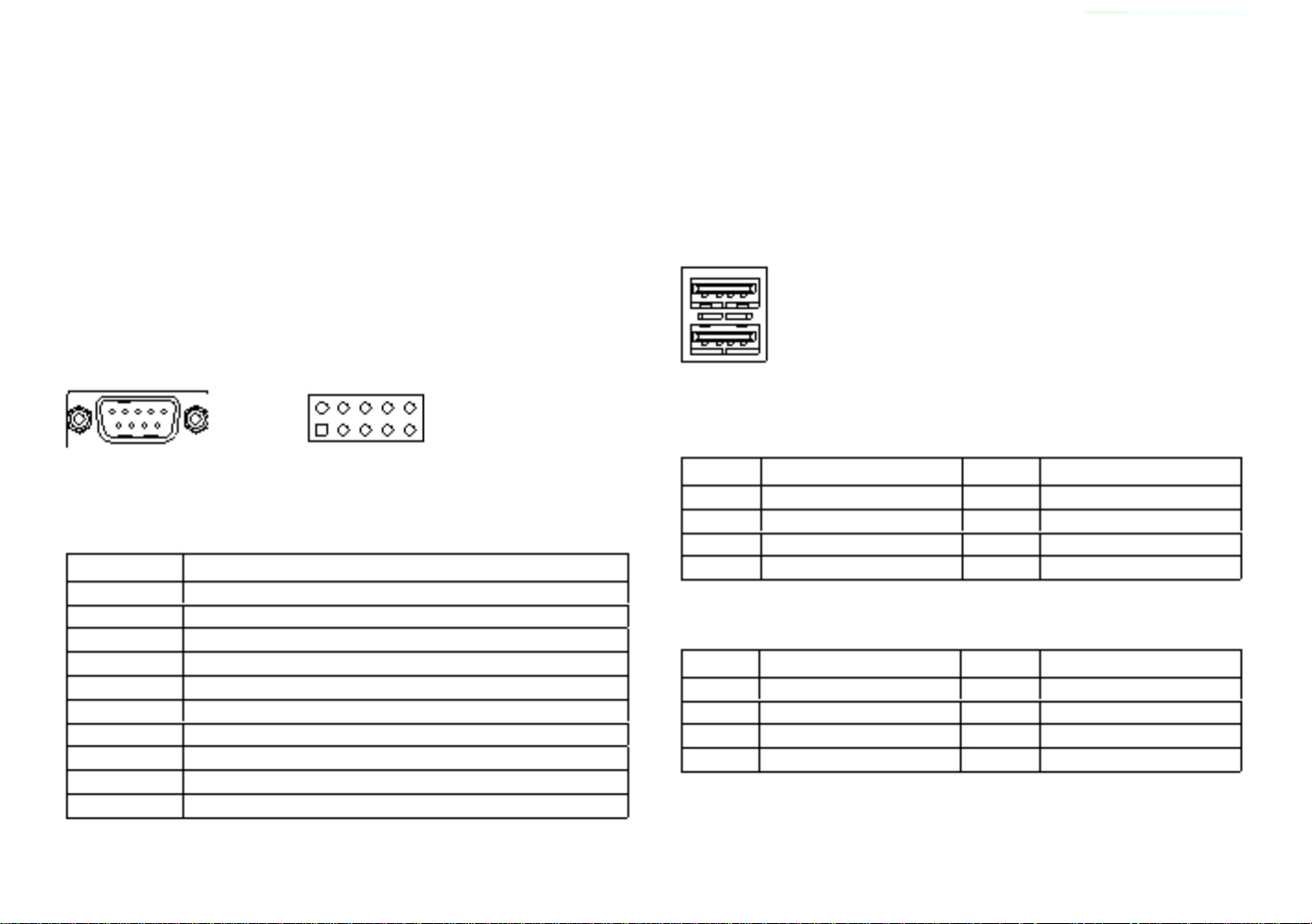
VGA Port
Connector type: DB-15 port, 15-pin D-Sub
Connector location: VGA1
5
1
3
2
4
Pin
1
2
3
4
5
Settings
DC+
DC+
DC-
DC-
GND
Pin
1
2
3
4
5
6
7
8
Definition
Red
Green
Blue
N/C
GND
GND
GND
GND
Pin
9
10
11
12
13
14
15
Definition
+5V
GND
N/C
DDC Data
HSYNC
VSYNC
DDC Clock
15
Line-out Jack
Connector type: 3.5mm Earphone Jack
Connector location: CN14
Definition
LOUT_R
JD
NC
LOUT_L
GND
GND
Pin
1
2
3
4
5
6
Page 21
Chapter 2: Jumpers and Connectors
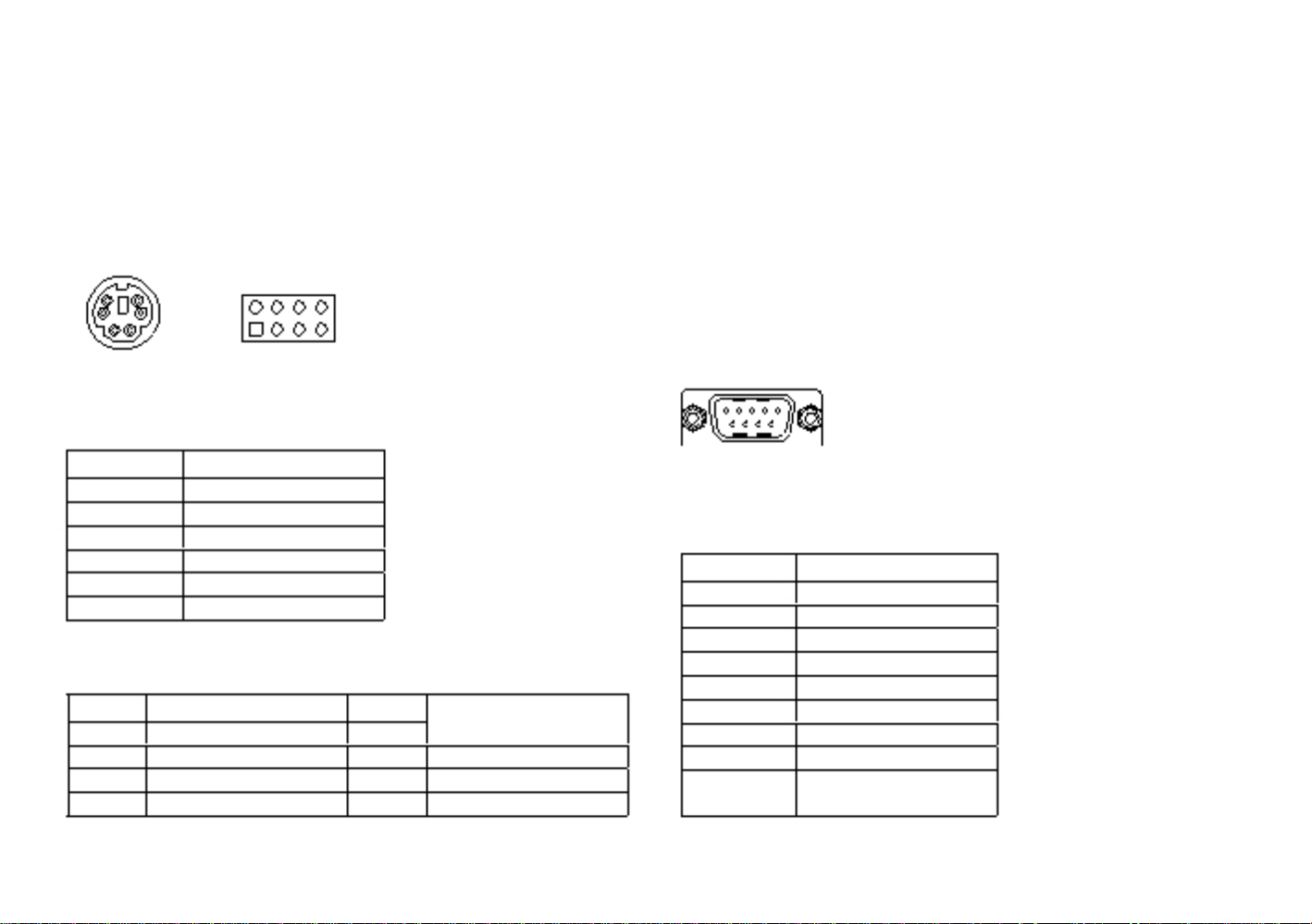
PS/2 Keyboard/Mouse Port
Connector type: PS/2, Mini-DIN-6, 2.0mm pitch
2x4 8-pin header, 2.54mm pitch
Connector location: JP4
6
4
5
3
2
1
8
7
COM2 Port: Serial Port RS232/422/485
AcuPanel 19
(Isolation protection with RS232/422/485)
Connector type: 9-pin D-Sub
Connector location: CN16
2
1
External Connector
Pin
1
2
3
4
5
6
Settings
KB_DATA
MS_DATA
GND
VCC5
KB_CLK
MS_CLK
Internal Connector
Pin
1
3
5
7
Definition
VCC5
KB_DATA
KB_CLK
GND
Pin
2
4
6
8
Definition
VCC5
MS_DATA
MS_CLK
GND
RS232
Pin
1
2
3
4
5
6
7
8
9
Definition
COM2_DCD
COM2_RXD
COM2_TXD
COM2_DTR
COM2_GND
COM2_DSR
COM2_RTS
COM2_CTS
COM2_RI (Could be a
+12V Power Pin)
16
Page 22
Chapter 2: Jumpers and Connectors
RS422
Pin
1
2
3
4
5
6
7
8
9
Definition
COM2_TXD-
COM2_TXD+
COM2_RXD+
COM2_RXD-
COM2_GND
COM2_RTS-
COM2_RTS+
COM2_CTS+
COM2_CTS- (Could be a
+12V Power Pin)
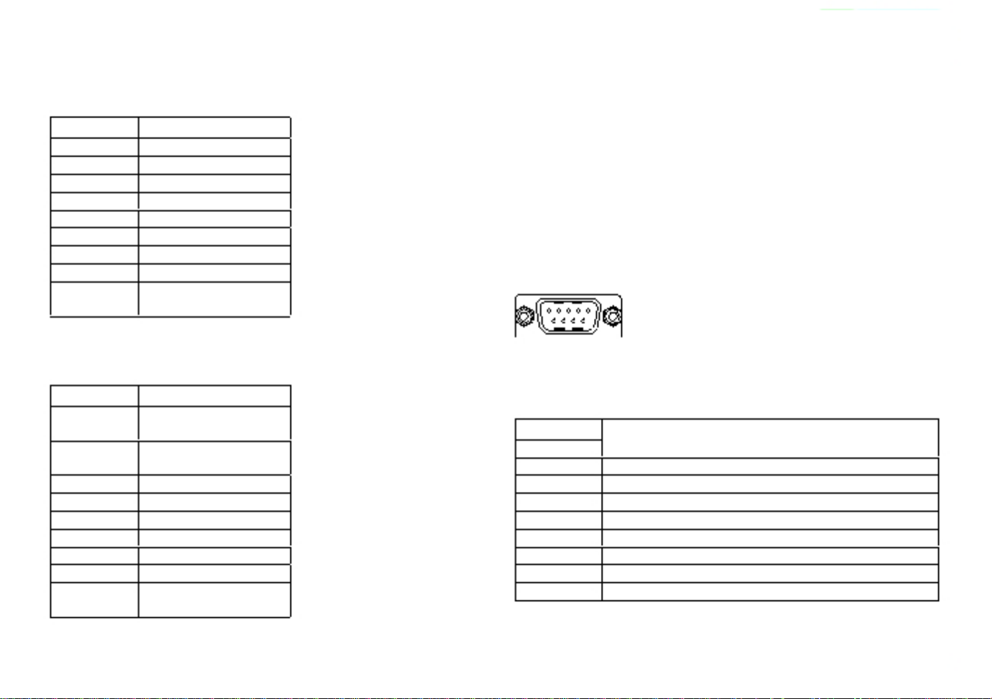
COM1 Port: Serial Port RS232/422/485
AcuPanel 19
(Isolation protection with RS232/422/485)
Connector type: 9-pin D-Sub
Connector location: CN15
RS485
Pin
1
2
3
4
5
6
7
8
9
Definition
COM2_TXD-
COM2_RXD-
COM2_TXD+
COM2_RXD+
Reserve
Reserve
Reserve
Reserve
Reserve
Reserve
Reserve (Could be a
+12V Power Pin)
RS232
Pin
1
2
3
4
5
6
7
8
9
Definition
COM1_DCD: Data Carrier Detect
COM1_RXD: Receive Data
COM1_TXD: Transmit Data
COM1_DTR: Data Terminal Ready
COM1_GND
COM1_DSR: Data Set Ready
COM1_RTS: Request To Send
COM1_CTS: Clear To Send
COM1_RI: Ring Indicator (Could be a +5V Power Pin)
17
Page 23
Chapter 2: Jumpers and Connectors
RS422
Pin
1
2
3
4
5
6
7
8
9
Definition
COM1_TXD-: Transmit Data Negative
COM1_TXD+: Transmit Data Positive
COM1_RXD+: Receive Data Positive
COM1_RXD-: Receive Data Negative
COM1_GND
COM1_RTS-: Request To Send Negative
COM1_RTS+: Request To Send Positive
COM1_CTS+: Clear To Send Positive
COM1_CTS-: Clear To Send Negative (Could be a +5V
Power Pin)
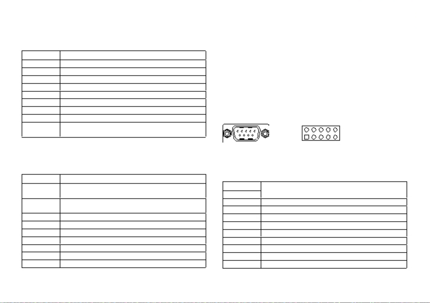
COM3 Port and Connector: Serial Port RS232
(Ring or +5V Power for Pin 9)
Connector type: 9-pin D-Sub
2x5 10-pin header, 2.0mm pitch
Connector location: CN9
2
1
10
9
RS485
Pin
1
2
3
4
5
6
7
8
9
Definition
COM1_TXD-: Transmit Data Negative
COM1_RXD-: Receive Data Negative
COM1_TXD+: Transmit Data Positive
COM1_RXD+: Receive Data Positive
Reserve
Reserve
Reserve
Reserve
Reserve
Reserve
Reserve (Could be a +5V Power Pin)
RS232
Pin
1
2
3
4
5
6
7
8
9
10
Definition
COM3_DCD
COM3_RXD
COM3_TXD
COM3_DTR
COM3_GND
COM3_DSR
COM3_RTS
COM3_CTS
COM3_RI (Could be a +5V Power Pin)
GND
18
Page 24
Chapter 2: Jumpers and Connectors
COM4 Port and Connector: Serial Port RS232
(Ring or +12V Power for Pin 9)
Connector type: 9-pin D-Sub
2x5 10-pin header, 2.0mm pitch
Connector location: CN10
USB Ports
Connector type: Dual USB port
Connector location: USB1 and USB2
2
1
10
9
RS232
Pin
1
2
3
4
5
6
7
8
9
10
Definition
COM4_DCD
COM4_RXD
COM4_TXD
COM4_DTR
COM4_GND
COM4_DSR
COM4_RTS
COM4_CTS
COM4_RI (Could be a +12V Power Pin)
GND
USB1
Pin
1
2
3
4
Definition
VCC5
USB0-
USB0+
GND
Pin
5
6
7
8
Definition
VCC5
USB1-
USB1+
GND
USB2
Pin
1
2
3
4
Definition
VCC5
USB2-
USB2+
GND
Pin
5
6
7
8
Definition
VCC5
USB3-
USB3+
GND
19
Page 25
Chapter 2: Jumpers and Connectors
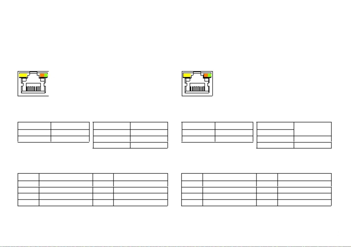
LAN2 Port
Connector type: RJ45 port with LEDs
Connector location: LAN2
LAN1 Port
Support Wake on LAN (WOL)
Connector type: RJ45 port with LEDs
Connector location: LAN1
ACT LINK
ACT
LINK
Act
Yellow blinking
Off
Status
Data activity
No activity
Link
Steady green
Steady orange
Off
Status
1000M link
100M link
10M or no link
Act
Yellow blinking
Off
Status
Data activity
No activity
Link
Steady green
Steady orange
Off
Status
1000M link
100M link
10M or no link
Pin
1
2
3
4
Definition
LAN2M0+
LAN2M0-
LAN2M1+
LAN2M2+
Pin
5
6
7
8
Definition
LAN2M2-
LAN2M1-
LAN2M3+
LAN2M3-
Pin
1
2
3
4
Definition
LAN1M0+
LAN1M0-
LAN1M1+
LAN1M2+
Pin
5
6
7
8
Definition
LAN1M2-
LAN1M1-
LAN1M3+
LAN1M3-
20
Page 26
Chapter 2: Jumpers and Connectors
Internal Connectors
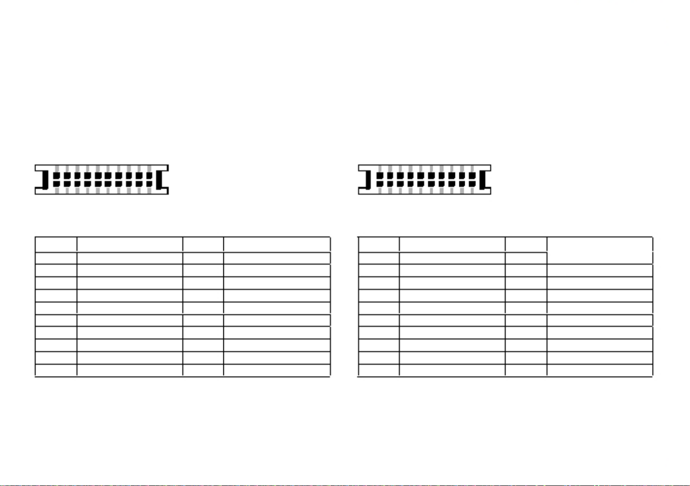
LVDS Channel 1
Connector type: 2x10 20-pin header, 1.25mm pitch
Connector location: CN5
LVDS Channel 2
Connector type: 2x10 20-pin header, 1.25mm pitch
Connector location: CN4
1
2
19
20
1
2
19
20
Pin
1
2
3
4
5
6
7
8
9
10
Definition
NC
NC
VDD
LVDS_DAT0+(Odd)
LVDS_DAT3+(Odd)
LVDS_DAT0-(Odd)
LVDS_DAT3-(Odd)
VDD
GND
LVDS_DAT1+(Odd)
Pin
11
12
13
14
15
16
17
18
19
20
Definition
LVDS_CLK1+(Odd)
LVDS_DAT1-(Odd)
LVDS_CLK1-(Odd)
GND
GND
+12V
LVDS_DAT2+(Odd)
+12V
LVDS_DAT2-(Odd)
GND
Pin
1
2
3
4
5
6
7
8
9
10
Definition
NC
NC
VDD
LVDS_DAT4+(Even)
LVDS_DAT7+(Even)
LVDS_DAT4-(Even)
LVDS_DAT7-(Even)
VDD
GND
LVDS_DAT5+(Even)
Pin
11
12
13
14
15
16
17
18
19
20
Definition
LVDS_CLK2+(Even)
LVDS_DAT5-(Even)
LVDS_CLK2-(Even)
GND
GND
+12V
LVDS_DAT6+(Even)
+12V
LVDS_DAT6-(Even)
GND
21
Page 27
Chapter 2: Jumpers and Connectors
Panel Backlight Connector
Connector type: 1x7 7-pin header JST, 2.5mm pitch
Connector location: J7
Touch Sensor Connector
Connector type: 1x5 5-pin header JST, 2.5mm pitch
Connector location: J9
7
1
5
1
Pin
1
2
3
4
Definition
VCC5
12V
12V
BKCTRL
Pin
5
6
7
Definition
GND
GND
BKLEN
Pin
1
2
3
4
5
4-wire
Left
Top
N/A
Right
Bottom
5-wire
LL (L)
UL (Y)
Sense (S)
LR (X)
UR (H)
22
Page 28

Chapter 2: Jumpers and Connectors
USB Connector
Connector type: 1x6 6-pin header JST, 2.5mm pitch
Connector location: J8
Bluetooth Connector
Connector type: 1x10 10-pin header, 1.0mm pitch
Connector location: J6
6
1
10
1
Pin
1
2
3
4
5
6
Definition
+5V
HUBUSB DM1-
HUBUSB DP1+
HUBUSB DM2-
HUBUSB DP2+
GND
Pin
1
2
3
4
5
Definition
GND
HUBUSB_DP3+
HUBUSB_DM3-
NC
NC
Pin
6
7
8
9
10
Definition
NC
NC
3.3V
NC
GND
23
Page 29

Chapter 2: Jumpers and Connectors
SATA Connector
Connector type: Standard Serial ATAII 7P (1.27mm, SATA-M-180)
Connector location: CN3
SATA DOM Power Connector
Connector type: 1x2 2-pin header, JST 2.5mm pitch
Connector location: J2
1
7
1
2
Pin
1
2
3
4
5
6
7
Definition
GND
TX0+
TX0-
GND
RX0-
RX0+
GND
Pin
1
2
Definition
+5V
GND
24
Page 30

Chapter 2: Jumpers and Connectors
Line-in/Mic-in Connector
Connector type: 2x4 8-pin header, 2.54mm pitch
Connector location: JP11
Speaker-out Connector
Connector type: 1x4 4-pin header, 2.54mm pitch
Connector location: J12
2
1
8
7
1
4
Line-in
Mic-in
Pin
1
3
5
7
Definition
LINE IN_LP
LINE IN_JD
GND
LINE IN_RP
Pin
2
4
6
8
Definition
MIC_L3
MIC_JD
GND
MIC_R3
Pin
1
2
3
4
Definition
OUT-L+
OUT-L-
OUT-R+
OUT-R-
25
Page 31

Chapter 2: Jumpers and Connectors
GPIO Connector
Connector type: 2x5 10-pin header, 2.0mm pitch
DB15 male 10-pin
Connector location: JP2
1
5
2
1
10
9
6
10
Internal Connector
Pin
1
3
5
7
9
Definition
+5V
GPIO22 (GPO)
GPIO23 (GPO)
NC
NC
Pin
2
4
6
8
10
Definition
GND
GPIO20 (GPI)
GPIO21 (GPI)
NC
NC
External Connector
Pin
1
3
5
7
9
Definition
+5V
GPIO21 (GPI)
NC
GPIO22 (GPO)
NC
Pin
2
4
6
8
10
Definition
GPIO20 (GPI)
NC
GND
GPIO23 (GPO)
NC
26
Page 32

Chapter 2: Jumpers and Connectors
DIO Connector
Connector type: 2x8 16-pin header, 2.0mm pitch
DB15 male 15-pin
Connector location: CN2
1
5
2
1
16
15
11
15
Internal Connector
Pin
1
3
5
7
9
11
13
15
Definition
DI1
DI2
DI3
DI4
NC
COM
GND
GND
External Connector
Pin
1
3
5
7
9
11
13
15
Definition
DI1
DI3
GND
NC
DO1
DO3
GND
GND
Pin
2
4
6
8
10
12
14
16
Definition
DO1
DO2
DO3
DO4
NC
NC
GND
GND
Pin
2
4
6
8
10
12
14
Definition
DI2
DI4
COM
NC
DO2
DO4
GND
DI1~DI4: Isolated digital input pins
DO1~DO4: Isolated digital output pins
COM: Common pin for connecting inductive loads of isolated output channels
DO1~DO4
GND: Isolated ground
27
Page 33

Chapter 2: Jumpers and Connectors
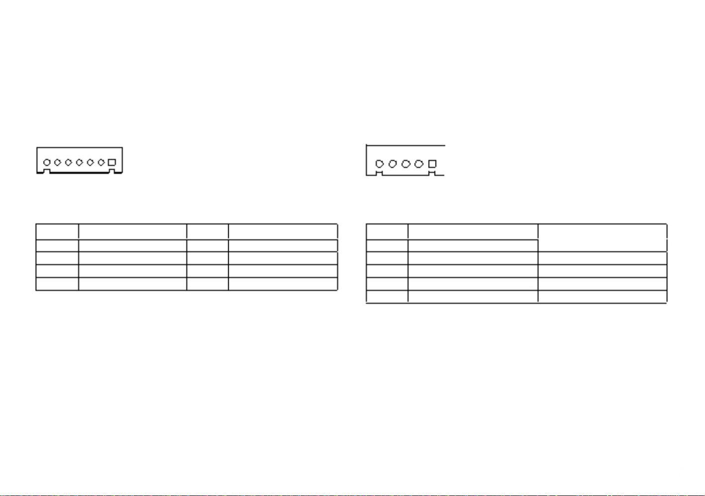
Power/HDD LED Indicator Connector
Connector type: 1x5 5-pin header JST, 2.0mm pitch
Connector location: J10
Backlight Control Input Connector
Connector type: 1x4 4-pin header JST, 2.0mm pitch
Connector location: J5
5
1
4
1
Pin
1
2
3
4
5
Definition
HDD_GND
HDD_PWR
PWR_GND
5VSB
VCC5
Pin
1
2
3
4
Definition
GND
Tact Switch input
PIR IN
VCC3
28
Page 34

Chapter 2: Jumpers and Connectors
Dimming Control Button Connector
Connector type: 1x5 5-pin header JST, 2.0mm pitch
Connector location: J4
SIM Card Slot
Connector location: CN8
C3
C2
C1
C7
C6
C5
5
1
Pin
1
2
3
4
5
Definition
GND
Decreased input
Increased input
Light sensor input
VCC3
Pin
C1
C2
C3
Definition
UIM_PWR
UIM_RST
UIM_CLK
Pin
C5
C6
C7
Definition
GND
UIM_VCCP
UIM_DAT
29
Page 35

Chapter 2: Jumpers and Connectors
Mini-PCIe Slot
Connector location: CN6
1 2
51
52
Pin
1
3
5
7
9
11
13
15
17
19
21
23
25
Definition
WAKE0#
NC
NC
PCIE_CLKREQ
GND
GPP_CLK1-
GPP_CLK1+
GND
NC
NC
GND
PCIE_RX2-
PCIE_RX2+
Pin
2
4
6
8
10
12
14
16
18
20
22
24
26
Definition
+3.3V_MINI
GND
+1.5V_MINI
SIM_PWR
SIM_DAT
SIM_CLK
SIM_RST
SIM_VCCP
GND
MINICARD1_DIS#
PCIE_RST#
+3.3V_MINI
GND
Pin
27
29
31
33
35
37
39
41
43
45
47
49
51
Definition
GND
GND
PCIE_TX3-
PCIE_TX3+
GND
GND
+3.3V_MINI
+3.3V_MINI
GND
NC
NC
NC
NC
Pin
28
30
32
34
36
38
40
42
44
46
48
50
52
Definition
+1.5V_MINI
SMB_CLK
SMB_DAT
GND
USB6-
USB6+
GND
NC
NC
NC
+1.5V_MINI
GND
+3.3V_MINI
30
Page 36

Chapter 2: Jumpers and Connectors
Mini-PCIe Slot
Connector location: CN7
1 2
51
52
Pin
1
3
5
7
9
11
13
15
17
19
21
23
25
Definition
WAKE0#
NC
NC
NC
GND
GPP_CLK1-
GPP_CLK1+
GND
NC
NC
GND
PCIE_RX2-
PCIE_RX2+
Pin
2
4
6
8
10
12
14
16
18
20
22
24
26
Definition
+3.3V_MINI
GND
+1.5V_MINI
NC
NC
NC
NC
NC
GND
MINICARD1_DIS#
PCIE_RST#
+3.3V_MINI
GND
Pin
27
29
31
33
35
37
39
41
43
45
47
49
51
Definition
GND
GND
PCIE_TX3-
PCIE_TX3+
GND
GND
+3.3V_MINI
+3.3V_MINI
GND
NC
NC
NC
NC
Pin
28
30
32
34
36
38
40
42
44
46
48
50
52
Definition
+1.5V_MINI
SMB_CLK
SMB_DAT
GND
USB6-
USB6+
GND
NC
NC
NC
+1.5V_MINI
GND
+3.3V_MINI
31
Page 37

Chapter 2: Jumpers and Connectors
CFast Card Slot
Connector type: Standard CFast connector
Connector location: J13
Power Button Connector
Connector type: 1x2 2-pin header, JST 2.0 mm pitch
Connector location: J11
1
2
S1
S7 PC1
PC17
Pin
S1
S2
S3
S4
S5
S6
S7
PC1
PC2
PC3
PC4
PC5
Definition
GND
SATA_TX1+
SATA_TX1-
GND
SATA_RX1-
SATA_RX1+
GND
CFAST_CDI
GND
NC
NC
NC
Pin
PC6
PC7
PC8
PC9
PC10
PC11
PC12
PC13
PC14
PC15
PC16
PC17
Definition
NC
GND
CFAST_LED1_C
CFAST_LED2_C
NC
NC
NC
VCC3
VCC3
GND
GND
CFAST_CDO
Pin
1
2
Definition
PWRBT
GND
32
Page 38

Chapter 2: Jumpers and Connectors
Block Diagram
AcuPanel 19
Panel 19” SXGA 128X1024
Maximum resolution:1920x1080
LVDS CON
LVDS CON
CH7511
DP to LVDS
Display Port
DDI PORT1
EEJ!QPSU1
VGA DB15P in (Slim Type)
Co-layout with BOX HEADER
Maximum resolution:1900x1200
VGA
HAD_SDI1
0-1-REAR
2-3-REAR
EES4
TQJ!3NC
Qbhf!32
1.2!.!Joufsobm!dpoofdups
epxo!tusfbn
3.!Cmvf!uppui
4-PENMUNT TOUCH
Controller
5-USB HUB 1-4
GENESYS GL850
6-7 –MINI CARD
QDJf!y2
USB 2.0
QDJf!y2
Qbhf!3:
QDJf!y2
STA 0 HDD
(DOM Support)
SATA 1 CFAST
Njoj!QDJF
XJGJ
Njoj!QDJF
4H
Qbhf!41
SATA GEN2
Ujhfs!Qpjou
QDI!ON21
471!cbmmt
28+28nn
Qbhf!29.31
MDJ
MQD
QDJf!y2
Hjhb!MBO
SK56
MBO!93685M
Qbhf!36
MBO!93685M
Qbhf!38
SK56
XPM!Tvqqpsu
Hjhb!MBO
SATA GEN2
IEB
HQJP3JO03PVU
LPC BUS
!EJP!5JO05PVU!JTPMBUJPO
MIC-IN
AUDIO ODEC
ALC886
LINE-IN
SUPER I/O
ITE8783
HEAD PHONE
DPN2 ST.34305330596
DPN3 ST.34305330596
DPN4 ST.343
DPN5 ST.343
!JTPMBUJPO
80 PORT
!JTPMBUJPO
AMP
TPS6047A4RHBR
THERMAL SENSOR *2
VOLTAGES *4
FAN *1
PS2 KB/MS
33
VGA
911
LVDS
IHDA
B
177
02
EES4!
*
)5 QD
3*
C!
J.
VT
!) UB
1!
+2
F!
3/ TB QD
HAD_SDI0
+2
F!
3/ TB QD
Page 39

Chapter 3: System Setup
Chapter 3: System Setup
Installing a SATA Hard Drive
CAUTION!
Prior to removing the chassis cover, make sure the unit's power
is off and disconnected from the power sources to prevent
electric shock or system damage.
1. Remove the mounting screws around the chassis cover and then remove
the cover.
The dots denote the locations of the screws.
34
Page 40

Chapter 3: System Setup
2. Remove the mounting screws of the drive bay.
3. Remove the drive bay. The drive bay is used to hold a SATA hard drive.
Mounting
screw
SATA power cable
and SATA cable
35
4. Place the SATA hard drive on the drive bay.
SATA drive
Drive bay
5. Align the mounting holes that are on the sides of the SATA drive
with the mounting holes on the drive bay and then use the provided
mounting screws to secure the drive in place.
Mounting
screw
Page 41

Chapter 3: System Setup
6. Place the SATA drive in the chassis and then use the provided mounting
screws to secure the drive in the chassis.
Connect the SATA data cable and SATA power cable to the
connectorson the SATA drive.
SATA drive
SATA data cable
SATA power cable
36
Installing a CFast Card
1. The CFast card socket is located on the rear top side of the chassis.
CFast card socket
2. Remove the mounting screws of the CFast socket's cover.
Mounting
screw
Page 42

Chapter 3: System Setup
3. With the CFast card's label facing up, insert the card until it is
completely seated in the socket.
4. Push the CFast card to remove the CFast card.
CFast card
37
Page 43

Chapter 3: System Setup
Installing a SODIMM
1. Remove the mounting screws around the chassis cover and then remove
the cover.
38
2. Remove the mounting screws on the metal support plate.
Page 44

Chapter 3: System Setup
3. Gently lift the motherboard support plate upwards and locate the
SODIMM socket underneath.
39
4. Insert the module into the socket at an approximately 30 degrees angle.
Apply firm even pressure to each end of the module until it slips into
the socket. The gold-plated connector on the edge of the module will
almost completely disappear inside the socket.
5. Push the module down until the clips on both sides of the socket lock
into position. You will hear a distinctive "click", indicating the module is
correctly locked into position.
SODIMM
SODIMM
socket
Note:
1. If only one SO DIMM is installed, please install to
the one closest to the panel.
2. The maximum RAM size is 4G (2x 2G or 1x 4G)
Page 45

Chapter 3: System Setup
Installing a SATA DOM
1. Remove the drive bay bracket. The SATA connector is readily accessible
upon removing the bracket.
SATA connector
2. Remove the screw.
40
Page 46

Chapter 3: System Setup
3. The SATA DOM package includes a supporting stud. The stud is used to
stabilize the SATA DOM module.
4. Install the supporting stud. Make sure the stud is fastened in place.
Supporting
stud
Supporting
stud
Cable
SATA DOM
41
Page 47

Chapter 3: System Setup
5. Connect one end of the provided cable to the connector on the
module.
6. Install the module to the SATA port via the connector at the solder side
of the module and then secure the module using the mounting screw
you removed in step 2.
Cable
Connector on
the module
SATA DOM
Mounting
screw
42
Page 48

Chapter 3: System Setup
7. Connect the other end of the cable to the connector on the board.
43
Page 49

Chapter 3: System Setup
Installing a Mini PCIe Module
The Mini PCIe module package includes the following items:
RALINK 802.11b/g/n 2T3R wireless mini card module kit QCOM:Q802XKN
3.5G module kit Sierra Wireless MC8790V
Mini PCIe Module
802.11b/g QN-MU-A0028 wireless mini card module kit
INTEL112.BNHMWG
Antennas
RF Cables
44
Page 50

Chapter 3: System Setup
If you are installing the 802.11b/g QN-MU-A0028 wireless mini card
module (half-size), before proceeding with the installation, please assemble
the Wi-Fi module bracket first by following the instructions below:
2. Tighten screws onto the mounting holes to secure the bracket.
1. Align the mounting holes on the Wi-Fi mini card module to the
mounting holes on the Wi-Fi module bracket.
Mounting holes
Wi-Fi module bracket
45
Page 51

Chapter 3: System Setup
Installing the Half-Size Mini PCIe Module
1. Insert the Mini PCIe module into the Mini PCIe slot at a 45 degrees
angle until the gold-plated connector on the edge of the module
completely disappears inside the slot.
Mini PCIe slot
Mini PCIe
module
2. Secure the module with mounting screws.
3. Please go to step 3 on page 69 to proceed.
46
Page 52

Chapter 3: System Setup
Installing the Full-Size Mini PCIe Module
1. Insert the Mini PCIe module into the Mini PCIe slot at a 45 degrees
angle until the gold-plated connector on the edge of the module
completely disappears inside the slot.
2. Secure the module with mounting screws.
Mounting
screw
Mini PCIe
module
Mini PCIe slot
Mounting
screw
47
Page 53

Chapter 3: System Setup
3. Attach one end of the RF cables onto the module.
4. Push the antenna hole cover.
RF cable
RF cable
48
Page 54

Chapter 3: System Setup
5. Remove the antenna hole covers.
6. Insert the antenna jack end of the cable through the antenna hole.
Antenna jack
end of the cable
49
Page 55

Chapter 3: System Setup
7. Insert the ring onto the antenna jack end of the cable.
8. Connect external antennas to the antenna jacks.
Antenna jack
Ring
Antenna jack
Ring
RF cable
Mini PCIe
module
Antenna
Antenna
50
Page 56

Chapter 3: System Setup
Installing a Bluetooth Module
The Bluetooth module package includes the following items:
Bluetooth module QCOMQBTM400-01(V7)
1. Remove the sticker on one side of the square rubber pad, then place
that side on the back of the Bluetooth module.
Square rubber pad
Module's backside
2. Connect the cable to the connector on the Bluetooth module.
Cable
Connector
51
Page 57

Chapter 3: System Setup
3. Remove the mounting screws of the drive bay.
4. Remove the drive bay and locate the Bluetooth connector and
mounting hole on the mainboard.
Bluetooth
connector
Mounting
hole
Mounting
screw
52
Page 58

Chapter 3: System Setup
5. Remove the sticker on the square rubber pad
6. Align the mounting hole on the Bluetooth module to the mounting hole
on the mainboard, then tighten screws to secure it. Once the module is
secured, connect the cable to the Bluetooth connector.
Sticker
Bluetooth
connector
Mounting
hole
Module's backside
53
Page 59

Chapter 3: System Setup
7. Install the drive bay back to its original position.
8. Attach one end of the RF cable onto the module.
Attach RF
cable to the module
9. Mount the other end of the cable to the Bluetooth mounting hole
located at the rear top panel of the chassis.
54
Page 60

Chapter 3: System Setup
Placing Panel Mount Hole Blocks
The AcuPanel 19 comes with panel mount hole blocks to cover the panel
mount openings on the chassis to prevent dust invasion. You can also
choose to cover the panel mount holes when VESA mount is used.
1. Locate the panel mount openings on the chassis.
Panel Mount Hole Block
55
2. Insert the hole block into the opening until it is pushed in completely.
Page 61

Chapter 3: System Setup
Installing the Power Adapter Bracket
1. Locate the mounting screws for the bracket on the back side of the
chassis.
2. Remove the mounting screws and store them in a safe place for later
use.
56
Page 62

Chapter 3: System Setup
3. Wire the power adapter cabling into the cable opening on the bracket,
then place the adapter inside the bracket.
Cable opening
Power adapter cable
57
Page 63

Chapter 3: System Setup
4. Turn the bracket over to the back side, and place the cable tie into the
two tie mounts.
5. Wrap the power adapter cable, then secure the cable firmly by tying the
cable tie.
Tie mount
Cable tie
58
Page 64

Chapter 3: System Setup
6. With the bracket still facing backwards, align the mounting holes on
the bracket to the mounting holes on the back of the chassis, then
tighten screws to secure it. Once secured, plug the power adapter cable
into the DC input.
DC input
59
Plugging the DC Power Cable
1. Plug the DC 4-pin DIN power jack (male) into the DC 4-pin DIN power
jack (female) that is on the system.
2. The table below shows the pin definition of the cable.
Color
Black
Red&Yellow
Blue&Black
Pin Definition
GND
DC+
DC-
Page 65

Chapter 3: System Setup
3. Slide the Panel PC through the hole until it is properly fitted against the
panel.
4. Position the mounting clamps along the rear edges of the Panel PC. The
first and second clamps must be positioned and secured diagonally prior
to mounting the rest of the clamps. Tighten the clamp's screw until it
touches the panel.
AcuPanel 19
Clamp
Panel
CAUTION!
Do not overtighten the screws to prevent damaging the
Panel PC.
60
366.00
436.00
Panel Mounting
1. Select a place on the panel where you will mount the Panel PC.
2. Cut out a shape on the panel that corresponds to the Panel PC's rear
dimensions.
The thickness of the panel (e.g. steel board, plank, acrylic board, wall, etc.)
where you will mount the Panel PC must not exceed 6mm. If the distance
between the front bezel and panel mount hole is too wide, it will not fit the panel
mount kit.
6mm
Page 66

Chapter 4: BIOS Setup
Chapter 4: BIOS Setup
This chapter describes how to use the BIOS setup program for the AcuPanel 19.
The BIOS screens provided in this chapter are for reference only and may
change if the BIOS is updated in the future.
To check for the latest updates and revisions, visit the Acura Embedded
Systems Inc.’s Web site at www.acuraembedded.com.
About BIOS Setup
The BIOS (Basic Input and Output System) Setup program is a menu driven
utility that enables you to make changes to the system configuration and
tailor your system to suit your individual work needs. It is a ROM-based
configuration utility that displays the system's configuration status and
provides you with a tool to set system parameters.
These parameters are stored in non-volatile battery-backed-up CMOS RAM that
saves this information even when the power is turned off. When the system is
turned back on, the system is configured with the values found in CMOS.
With easy-to-use pull down menus, you can configure such items as:
▪ Hard drives, diskette drives, and peripherals
▪ Video display type and display options
▪ Password protection from unauthorized use
▪ Power management features
The settings made in the setup program affect how the computer performs.
It is important, therefore, first to try to understand all the setup options, and
second, to make settings appropriate for the way you use the computer.
When to Configure the BIOS
▪ This program should be executed under the following conditions:
▪ When changing the system configuration
▪ When a configuration error is detected by the system and you are
prompted to make changes to the setup program
▪ When resetting the system clock
▪ When redefining the communication ports to prevent any conflicts
▪ When making changes to the Power Management configuration
▪ When changing the password or making other changes to the security
setup
Normally, CMOS setup is needed when the system hardware is not consistent
with the information contained in the CMOS RAM, whenever the CMOS
RAM has lost power, or the system features need to be changed.
Default Configuration
Most of the configuration settings are either predefined according to
the Load Optimal Defaults settings which are stored in the BIOS or are
automatically detected and configured without requiring any actions. There
are a few settings that you may need to change depending on your system
configuration.
61
Page 67

Chapter 4: BIOS Setup
Entering Setup
When the system is powered on, the BIOS will enter the Power-On Self Test
(POST) routines. These routines perform various diagnostic checks; if an
error is encountered, the error will be reported in one of two different ways:
▪ If the error occurs before the display device is initialized, a series of beeps
will be transmitted.
▪ If the error occurs after the display device is initialized, the screen will
display the error message.
Powering on the computer and immediately pressing <Del> allows you to
enter Setup. Another way to enter Setup is to power on the computer and
wait for the following message during the POST:
Ctrl Alt
TO ENTER SETUP BEFORE BOOT PRESS + +
Press the key to enter Setup:
Legends
Key
Function
Moves the highlight left or right to select a menu.
Moves the highlight up or down between
sub¬menus or fields.
Exits the BIOS Setup Utility.
Scrolls forward through the values or options of the
highlighted field.
Scrolls backward through the values or options of
the highlighted field.
Selects a field.
Displays General Help.
Load previous values.
Load optimized default values.
Saves and exits the Setup program.
Press <Enter> to enter the highlighted sub¬menu
62
Scroll Bar
When a scroll bar appears to the right of the setup screen, it indicates that
there are more available fields not shown on the screen. Use the up and
down arrow keys to scroll through all the available fields.
Submenu
When " " appears on the left of a particular field, it indicates that a
submenu which contains additional options are available for that field. To
display the submenu, move the highlight to that field and press .
Page 68

Chapter 4: BIOS Setup
BIOS Setup Utility
Once you enter the AMI BIOS Setup Utility, the Main Menu will appear on
the screen. The main menu allows you to select from several setup functions
and one exit. Use arrow keys to select among the items and press
accept or enter the submenu.
Main
to
Intel RC Version
Displays the Intel Reference Code version.
Aptio Setup Utility - Copyright (C) 2011 American Megatrends, Inc.
Advanced Chipset Boot Security Save & Exit
Main
The Main menu is the first screen that you will see when you enter the BIOS
Setup Utility.
Intel RC Version
INTEL CEDARVIEW
INTEL MRC
INTEL NM10
INTEL P-UNIT
INTEL IGFX VBIOS
INTEL ACPI
0.9.0-1
1.00
1.6.0
012
1071
0.9.0-1
Aptio Setup Utility - Copyright (C) 2011 American Megatrends, Inc.
Advanced Chipset Boot Security
Main
BIOS Information
BIOS Vendor
Core Version
Compliancy
Project Version
Build Date and Time
Intel RC Version
System Date
System Time
Access Level
Save & Exit
Intel Reference Code version
American Megatrends
4.6.5.1
UEFI 2.3; PI 1.2
AD27-002
06/27/2012 09:31:18
: Select Screen
: Select Item
Enter: Select
+/-: Change Opt.
F1: General Help
F2: Previous Values
F3: Optimized Defaults
F4: Save & Exit
ESC: Exit
[Wed 07/18/2012]
[18:26:37]
Administrator
Version 2.14.1219. Copyright (C) 2011 American Megatrends, Inc.
: Select Screen
: Select Item
Enter: Select
+/-: Change Opt.
F1: General Help
F2: Previous Values
F3: Optimized Defaults
F4: Save & Exit
ESC: Exit
Version 2.14.1219. Copyright (C) 2011 American Megatrends, Inc.
63
System Date
The date format is <day>, <month>, <date>, <year>. Day displays a day,
from Monday to Sunday. Month displays the month, from January to
December. Date displays the date, from 1 to 31. Year displays the year, from
1999 to 2099.
System Time
The time format is <hour>, <minute>, <second>. The time is based on the
24-hour military-time clock. For example, 1 p.m. is 13:00:00. Hour displays
hours from 00 to 23. Minute displays minutes from 00 to 59. Second displays
seconds from 00 to 59.
Access Level
Displays the access level of the current user in the BIOS.
Page 69

Chapter 4: BIOS Setup
Advanced
The Advanced menu allows you to configure your system for basic operation.
Some entries are defaults required by the system board, while others, if
enabled, will improve the performance of your system or let you set some
features according to your preference.
Setting incorrect field values may cause the system to
malfunction.
Aptio Setup Utility - Copyright (C) 2011 American Megatrends, Inc.
Main Advanced Chipset Boot Security
Legacy OpROM Support
Launch Lan1 PXE OpROM
Launch Lan2 PXE OpROM
CPU Configuration
IDE Configuration
USB Configuration
Super IO Configuration
H/W Monitor
Launch LAN1/2 PXE OpROM
Enables or disables the boot option for legacy network devices connected
to LAN1 and LAN2.
[Disabled]
[Disabled]
Save & Exit
Enable or Disable Boot Option
for Lan1
Launch Lan1 PXE OpROM
Disabled
Enabled
: Select Screen
: Select Item
Enter: Select
+/-: Change Opt.
F1: General Help
F2: Previous Values
F3: Optimized Defaults
F4: Save & Exit
ESC: Exit
Version 2.14.1219. Copyright (C) 2011 American Megatrends, Inc.
64
CPU Configuration
This section is used to configure the CPU.
Aptio Setup Utility - Copyright (C) 2011 American Megatrends, Inc.
Advanced
Hyper-Threading
This field is used to enable or disable hyper-threading.
Execute Disable Bit
This field is used to enable or disable execute disable bit. When this field is
set to Disabled, it will force the XD feature flag to always return to 0. XD can
prevent certain classes of malicious buffer overflow attacks when combined
with a supporting OS (Windows Server 2003 SP1, Windows XP SP2,
SuSE Linux 9.2, RedHat Enterprise 3 Update 3).
Intel(R) Atom (TM) CPU
Supported
2132 MHZ
533MHZ
16
16
533MHZ
30661
262
2x56 k
2x512 k
Dual
Supported
[Enabled]
[Enabled]
[Disabled]
Enabled for Windows XP and
Linux (OS optimized for Hyper-
Threading Technology) and
Disabled for other OS (OS not
optimized for Hyper-Threading
Technology).
CPU Configuration
Processor Type
EMT64
Proceddor Speed
System Bus Speed
Ratio Status
Actual Ratio
System Bus Speed
Processor Stepping
Microcode Revision
L1 Cache RAM
L2 Cache RAM
Processor Core
Hyper-Threading
Hyper-Threading
Execute Disable Bit
Limit CPUID Maximum
: Select Screen
: Select Item
Enter: Select
+/-: Change Opt.
F1: General Help
F2: Previous Values
F3: Optimized Defaults
F4: Save & Exit
ESC: Exit
Limit CPUID Maximum
The CPUID instruction of some newer CPUs will return a value greater
than 3. The default is Disabled because this problem does not exist in
the Windows series operating systems. If you are using an operating system
other than Windows, this problem may occur. To avoid this problem, you
enable this field to limit the return value to 3 or lesser than 3.
Version 2.14.1219. Copyright (C) 2011 American Megatrends, Inc.
Page 70

Chapter 4: BIOS Setup
IDE Configuration
This section is used to configure the IDE devices.
Aptio Setup Utility - Copyright (C) 2011 American Megatrends, Inc.
Advanced
SATA Port0
SATA Port1
Not Present
Not Present
Select a configuraton for SATS
Controller
Configure SATA as
Configures the SATA as IDE or AHCI mode.
IDE
AHCI
This option configures the Serial ATA drives as Parallel ATA physical
storage device.
This option configures the Serial ATA drives to use AHCI (Advanced
Host Controller Interface). AHCI allows the storage driver to enable
the advanced Serial ATA features which will increase storage
performance.
SATA Controller(s)
Configure SATA as
[Enabled]
[AHCI]
Configure SATA as
IDE
AHCI
: Select Screen
: Select Item
Enter: Select
+/-: Change Opt.
F1: General Help
F2: Previous Values
F3: Optimized Defaults
F4: Save & Exit
ESC: Exit
Version 2.14.1219. Copyright (C) 2011 American Megatrends, Inc.
SATA Controller(s)
Enables or disables SATA controller.
65
USB Configuration
This section is used to configure USB devices.
Aptio Setup Utility - Copyright (C) 2011 American Megatrends, Inc.
Advanced
USB Configuration
USB Devices:
1 Keyboard, 1 Hub
Legacy USB Support
EHCI Hand-off
Device reset time-out
[Auto]
[Enabled]
[40 sec]
Enables Legacy USB support.
AUTO option disables legacy
support if no USB devices are
connected. DISABLE option will
keep USB devices available
only for EFI applications.
: Select Screen
: Select Item
Enter: Select
+/-: Change Opt.
F1: General Help
F2: Previous Values
F3: Optimized Defaults
F4: Save & Exit
ESC: Exit
Version 2.14.1219. Copyright (C) 2011 American Megatrends, Inc.
Legacy USB Support
Due to the limited space of the BIOS ROM, the support for legacy USB keyboard (in DOS mode) is by default set to Disabled. With more BIOS ROM
space available, it will be able to support more advanced features as well as
provide compatibility to a wide variety of peripheral devices.
If a PS/2 keyboard is not available and you need to use a USB keyboard
to install Windows (installation is performed in DOS mode) or run any program
under DOS, set this field to Enabled.
EHCI Hand-off
This is a workaround for OSs that does not support EHCI hand-off. The EHCI
ownership change should be claimed by the EHCI driver.
Device reset time-out
Selects the USB mass storage device's start unit command timeout.
Page 71

Chapter 4: BIOS Setup
Super IO Configuration
This section is used to configure serial ports 0 to 4.
Aptio Setup Utility - Copyright (C) 2011 American Megatrends, Inc.
Advanced
Super IO Configuration
Super IO Chip
Serial Port 0 Configuration
Serial Port 1 Configuration
Serial Port 2 Configuration
Serial Port 3 Configuration
Set Parameters of Serial Port
0 (COMA)
Serial Port 0 Configuration
This section is used to configure serial port 0.
Aptio Setup Utility - Copyright (C) 2011 American Megatrends, Inc.
Advanced
Serial Port 0 Configuration
Serial Port
Device Settings
Change Settings
Onboard Serial Port 0 Mode
Onboard Serial Port Max Baud Rate
Enable or Disable Serial Port
(COM)
IT8783F
[Enabled]
IO=3F8h; IRQ=4;
[IO=3F8h; IRQ=4;]
[RS232]
[115200 bps]
: Select Screen
: Select Item
Enter: Select
+/-: Change Opt.
F1: General Help
F2: Previous Values
F3: Optimized Defaults
F4: Save & Exit
ESC: Exit
: Select Screen
: Select Item
Enter: Select
+/-: Change Opt.
F1: General Help
F2: Previous Values
F3: Optimized Defaults
F4: Save & Exit
ESC: Exit
Version 2.14.1219. Copyright (C) 2011 American Megatrends, Inc.
Super IO Chip
Displays the Super I/O chip used on the board.
Version 2.14.1219. Copyright (C) 2011 American Megatrends, Inc.
Serial Port
Enables or disables the serial port.
Change Settings
Selects an optimal setting for the Super IO device.
Onboard Serial Port 0 Mode
This field is used to configure the mode of serial port 0 as RS232, RS422,
RS485 or RS485 AUTO.
66
Page 72

Chapter 4: BIOS Setup
Onboard Serial Port Max Baud Rate
This field configures the maximum baud rate of the serial port 0, the options
are 115200 bps and 921600 bps.
Aptio Setup Utility - Copyright (C) 2011 American Megatrends, Inc.
Main Advanced Chipset Boot Security
Serial Port 0 Configuration
Serial Port
Device Settings
Change Settings
Onboard Serial Port 0 Mode
Onboard Serial Port Max Baud Rate
Serial Port 1 Configuration
This section is used to configure serial port 1.
Aptio Setup Utility - Copyright (C) 2011 American Megatrends, Inc.
Advanced
Serial Port 1 Configuration
Serial Port
Device Settings
Change Settings
Onboard Serial Port 1 Mode
Onboard Serial Port Max Baud Rate
Enable or Disable Serial Port
(COM)
[Enabled]
IO=3F8H; IRQ=4;
[IO=3F8H; IRQ=4;]
[RS232]
[115200
bps]
Save & Exit
Change the Serial Port Max Baud
Rate. Select <115200 bps> or
<921600 bps>
[Enabled]
IO=2F8h; IRQ=3;
[IO=2F8h; IRQ=3;]
[RS232]
[115200 bps]
Onboard Serial Port Max Baud Rate
115200 bps
921600 bps
: Select Screen
: Select Item
Enter: Select
+/-: Change Opt.
F1: General Help
F2: Previous Values
F3: Optimized Defaults
F4: Save & Exit
ESC: Exit
: Select Screen
: Select Item
Enter: Select
+/-: Change Opt.
F1: General Help
F2: Previous Values
F3: Optimized Defaults
F4: Save & Exit
ESC: Exit
Version 2.14.1219. Copyright (C) 2011 American Megatrends, Inc.
Version 2.14.1219. Copyright (C) 2011 American Megatrends, Inc.
Serial Port
Enables or disables the serial port.
Change Settings
Selects an optimal setting for the Super IO device.
Onboard Serial Port 1 Mode
This field is used to configure the mode of serial port 1 as RS232, RS422,
RS485 or RS485 AUTO.
67
Page 73

Chapter 4: BIOS Setup
Onboard Serial Port Max Baud Rate
This field configures the maximum baud rate of the serial port 1, the options
are 115200 bps and 921600 bps.
Aptio Setup Utility - Copyright (C) 2011 American Megatrends, Inc.
Main Advanced Chipset Boot Security
Serial Port 1 Configuration
Serial Port
Device Settings
Change Settings
Onboard Serial Port 1 Mode
Onboard Serial Port Max Baud Rate
Serial Port 2 Configuration
This section is used to configure serial port 2.
Aptio Setup Utility - Copyright (C) 2011 American Megatrends, Inc.
Advanced
Serial Port 2 Configuration
Serial Port
Device Settings
Change Settings
Onboard Serial Port Max Baud Rate
Enable or Disable Serial Port
(COM)
[Enabled]
IO=2F8H; IRQ=3;
[IO=2F8H; IRQ=3;]
[RS232]
[115200
bps]
Save & Exit
Change the Serial Port Max Baud
Rate. Select <115200 bps> or
<921600 bps>
[Enabled]
IO=3E8h; IRQ=7;
[IO=3E8h; IRQ=7;]
[115200 bps]
Onboard Serial Port Max Baud Rate
115200 bps
921600 bps
: Select Screen
: Select Item
Enter: Select
+/-: Change Opt.
F1: General Help
F2: Previous Values
F3: Optimized Defaults
F4: Save & Exit
ESC: Exit
: Select Screen
: Select Item
Enter: Select
+/-: Change Opt.
F1: General Help
F2: Previous Values
F3: Optimized Defaults
F4: Save & Exit
ESC: Exit
Version 2.14.1219. Copyright (C) 2011 American Megatrends, Inc.
Version 2.14.1219. Copyright (C) 2011 American Megatrends, Inc.
Serial Port
Enables or disables the serial port.
Change Settings
Selects an optimal setting for the Super IO device.
68
Page 74

Chapter 4: BIOS Setup
Onboard Serial Port Max Baud Rate
This field configures the maximum baud rate of the serial port 2, the options
are 115200 bps and 921600 bps.
Aptio Setup Utility - Copyright (C) 2011 American Megatrends, Inc.
Main Advanced Chipset Boot Security
Serial Port 2 Configuration
Serial Port
Device Settings
Change Settings
Onboard Serial Port Max Baud Rate
Serial Port 3 Configuration
This section is used to configure serial port 3.
Aptio Setup Utility - Copyright (C) 2011 American Megatrends, Inc.
Advanced
Serial Port 3 Configuration
Serial Port
Device Settings
Change Settings
Onboard Serial Port Max Baud Rate
Enable or Disable Serial Port
(COM)
[Enabled]
IO=3E8H; IRQ=7;
[IO=3E8H; IRQ=7;]
[115200 bps]
Save & Exit
Change the Serial Port Max Baud
Rate. Select <115200 bps> or
<921600 bps>
[Enabled]
IO=2E8h; IRQ=6;
[IO=2E8h; IRQ=6;]
[115200 bps]
Onboard Serial Port Max Baud Rate
115200 bps
921600 bps
: Select Screen
: Select Item
Enter: Select
+/-: Change Opt.
F1: General Help
F2: Previous Values
F3: Optimized Defaults
F4: Save & Exit
ESC: Exit
: Select Screen
: Select Item
Enter: Select
+/-: Change Opt.
F1: General Help
F2: Previous Values
F3: Optimized Defaults
F4: Save & Exit
ESC: Exit
Version 2.14.1219. Copyright (C) 2011 American Megatrends, Inc.
Version 2.14.1219. Copyright (C) 2011 American Megatrends, Inc.
Serial Port
Enables or disables the serial port.
Change Settings
Selects an optimal setting for the Super IO device.
69
Page 75

Chapter 4: BIOS Setup
Onboard Serial Port Max Baud Rate
This field configures the maximum baud rate of the serial port 3, the options
are 115200 bps and 921600 bps.
Aptio Setup Utility - Copyright (C) 2011 American Megatrends, Inc.
Main Advanced Chipset Boot Security
Serial Port 3 Configuration
Serial Port
Device Settings
Change Settings
Onboard Serial Port Max Baud Rate
H/W Monitor
This section is used to configure the hardware temperature, fan speed and
voltages.
Aptio Setup Utility - Copyright (C) 2011 American Megatrends, Inc.
Main Advanced Chipset Boot Security Save & Exit
Pc Health Status
CPU Temperature
System Temperature
CPU:Vcore
+3.3V
+5V
+12V
[Enabled]
IO=2E8H; IRQ=6;
[IO=2E8H; IRQ=6;]
[115200 bps]
Save & Exit
Change the Serial Port Max Baud
Rate. Select <115200 bps> or
<921600 bps>
: +39 C
: +39 C
: +1.168 V
: +3.328 V
: +5.017 V
: +11.827 V
Onboard Serial Port Max Baud Rate
115200 bps
921600 bps
: Select Screen
: Select Item
Enter: Select
+/-: Change Opt.
F1: General Help
F2: Previous Values
F3: Optimized Defaults
F4: Save & Exit
ESC: Exit
: Select Screen
: Select Item
Enter: Select
+/-: Change Opt.
F1: General Help
F2: Previous Values
F3: Optimized Defaults
F4: Save & Exit
ESC: Exit
Version 2.14.1219. Copyright (C) 2011 American Megatrends, Inc.
Version 2.14.1219. Copyright (C) 2011 American Megatrends, Inc.
70
Page 76

Chapter 4: BIOS Setup
Chipset
This section is used to configure the system based on the specific features
of the chipset.
Host Bridge
Displays the memory information
Aptio Setup Utility - Copyright (C) 2011 American Megatrends, Inc.
Main
Host Bridge
South Bridge
Advanced Chipset Boot Security
Save & Exit
Host Bridge Parameters
Aptio Setup Utility - Copyright (C) 2011 American Megatrends, Inc.
Advanced Chipset Boot Security
Main
Intel IGD Configuration
******* Memory Information*******
Memory Frequency
Total Memory
Save & Exit
Config Intel IGD Settings
1067 MHz (DDR3)
4096 MB
: Select Screen
: Select Item
Enter: Select
+/-: Change Opt.
F1: General Help
F2: Previous Values
F3: Optimized Defaults
F4: Save & Exit
ESC: Exit
: Select Screen
: Select Item
Enter: Select
+/-: Change Opt.
F1: General Help
F2: Previous Values
F3: Optimized Defaults
F4: Save & Exit
ESC: Exit
Version 2.14.1219. Copyright (C) 2011 American Megatrends, Inc.
Version 2.14.1219. Copyright (C) 2011 American Megatrends, Inc.
Setting incorrect field values may cause the system to
malfunction.
71
Page 77

Chapter 4: BIOS Setup
Intel® IGD Configuration
This section is used to configure the Intel® IGD Graphic configurations.
Aptio Setup Utility - Copyright (C) 2011 America Megatrends, Inc.
Main Advanced Chipset Boot Security
Intel IGD Configuration
IGFX - Boot Type
LCD Panel Type
Backlight Control Select
Backlight On/Off Reverse
Backlight Dimming Control Select
Backlight
Fixed Graphics Memory Size
[LVDS]
1280x1024 (19inch)
[Pyroelectric sensor]
[Normal]
[Manual]
[100%]
[128MB]
IGFX - Boot Type
Save & Exit
Select the Video Device
Which will be activated
during POST.
This has no effect if
external graphics present.
CRT
LVDS
LVDS + CRT
CRT + HDMI
: Select Screen
: Select Item
Enter: Select
+/-: Change Opt.
F1: General Help
F2: Previous Values
F3: Optimized Defaults
F4: Save & Exit
ESC: Exit
Backlight On/Off Reverse
Please configure this option only when changing the panel, otherwise the
display may not work.
Backlight Dimming Control Select
The options are Tact Switch, Manual and Light sensor.
The default setting is Tact Switch for AcuPanel 19 and the
Backlight option below will not be configurable, please use the brightness
button on the panel to adjust it.
Backlight
Adjusts the brightness of the backlight.
Fixed Graphics Memory Size
This field is used to configure the memory size of the fixed graphics, the
options are 128MB and 256MB.
Version 2.14.1219. Copyright (C) 2011 American Megatrends, Inc.
IGFX - Boot Type
This field is used to configure which video device will be activated during
POST. This has no effect if external graphics present. The options are CRT,
LVDS, LVDS + CRT and CRT + HDMI.
Backlight Control Select
The available options are Pyroelectric sensor and Tact Switch. The default
setting is Tact Switch for AcuPanel19, and the Backlight On/Off button is functional
only in this mode.
72
Page 78

Chapter 4: BIOS Setup
South Bridge
Aptio Setup Utility - Copyright (C) 2011 American Megatrends, Inc.
Main Advanced Chipset
Azalia Controller
SMBus Controller
Boot
[HD Audio]
[Enabled]
Security
Save & Exit
Azalia Controller
High Precision Event Timer Configuration
High Precision Timer
Restore AC Power Loss
Blue-tooth
Beep
[Enabled]
[Power On]
[Enabled]
[Enabled]
: Select Screen
: Select Item
Enter: Select
+/-: Change Opt.
F1: General Help
F2: Previous Values
F3: Optimized Defaults
F4: Save & Exit
ESC: Exit
Version 2.14.1219. Copyright (C) 2011 American Megatrends, Inc.
Azalia Controller
This section disables Azalia or enables HD Audio.
SMBus Controller
This section is used to disable or enable SMBus controller.
High Precision Timer
This section is used to configure High Precision Event Timer.
Restore AC Power Loss
Power Off
When power returns after an AC power failure, the system's power is
off. You must press the Power button to power-on the system.
Power On
When power returns after an AC power failure, the system will automatically
power-on.
Last State
When power returns after an AC power failure, the system will return
to the state where you left off before power failure occurs. If the
system's power is off when AC power failure occurs, it will remain
off when power returns. If the system's power is on when AC power
failure occurs, the system will power-on when power returns.
Blue-tooth
Enables or disables blue-tooth, settings for the optional Bluetooth module
QCOM:QBTM400-01(V7).
Beep
Enables or disables beep.
73
Page 79

Chapter 4: BIOS Setup
Boot
This section is used to configure the boot features.
Aptio Setup Utility - Copyright (C) 2011 American Megatrends, Inc.
Main Advanced Chipset Boot Security
Boot Configuration
Setup Prompt Timeout
Bootup NumLock State
Quiet Boot
CSM16 Module Version
GateA20 Active
Option ROM Messages
Interrupt 19 Capture
Boot Option Priorities
Boot Option #1
Hard Drive BBS Priorities
1
[On]
[Disabled]
07.65
[Upon Request]
[Force BIOS]
[Disabled]
Save & Exit
Number of seconds to wait
for setup activation key.
65535(0xFFFF) means indefinite
waiting.
Quiet Boot
Enabled
Disabled
GateA20 Active
Upon Request
Always
Displays OEM logo instead of the POST messages.
Displays normal POST messages.
GA20 can be disabled using BIOS services.
Do not allow disabling GA20; this option is useful when
any RT code is executed above 1MB.
[SATA SM: 4GB SATA...]
: Select Screen
: Select Item
Enter: Select
+/-: Change Opt.
F1: General Help
F2: Previous Values
F3: Optimized Defaults
F4: Save & Exit
ESC: Exit
Option ROM Messages
This field is used to set display mode for Option ROM.
Interrupt 19 Capture
Allows Option ROMs to trap Interrupt 19 when enabled.
Boot Option Priorities
Adjust the boot sequence of the system. Boot Option #1 is the first boot
device that the system will boot from, next will be #2 and so forth.
Version 2.14.1219. Copyright (C) 2011 American Megatrends, Inc.
Setup Prompt Timeout
This section configures the number of seconds to wait for the setup
activation key.
Bootup NumLock State
This allows you to determine the default state of the numeric keypad. By
default, the system boots up with NumLock on wherein the function of the numeric
keypad is the number keys. When set to Off, the function of the numeric
keypad is the arrow keys.
74
Page 80

Chapter 4: BIOS Setup
Hard Drive BBS Priorities
Sets the order of the legacy devices in this group.
Aptio Setup Utility - Copyright (C) 2011 American Megatrends, Inc.
Main Advanced Chipset Boot Security Save & Exit
Boot Option #1
[SATA SM: 4GB SATA . . .]
Sets the system boot order
: Select Screen
: Select Item
Enter: Select
+/-: Change Opt.
F1: General Help
F2: Previous Values
F3: Optimized Defaults
F4: Save & Exit
ESC: Exit
Version 2.14.1219. Copyright (C) 2011 American Megatrends, Inc.
75
Page 81

Chapter 4: BIOS Setup
Security
Aptio Setup Utility - Copyright (C) 2011 American Megatrends, Inc.
Main Advanced Chipset Boot Security
Password Description
If ONLY the Administrator's password is set,
then this only limits access to Setup and is
only asked for when entering Setup.
If ONLY the User's password is set, then this
is a power on password and must be entered to
boot or enter Setup. In Setup the User Will
have Administrator rights.
The password length must be
in the following range:
Minimum length
Maximum
Administrator Password
User Password
3
20
Save & Exit
Set Administrator Password
Save & Exit
Aptio Setup Utility - Copyright (C) 2011 American Megatrends, Inc.
Main Advanced Chipset Boot Security
Save Changes and Exit
Discard Changes and Exit
Save Changes and Reset
Discard Changes and Reset
Save Options
Save Changes
Discard Changes
Restore Defaults
Save as User Defaults
Restore User Defaults
Boot Override
SATA SM: 4GB SATA Flash Drive
Launch EFI Shell from filesystem device
Save & Exit
Exit systm setup after
saving the changes.
: Select Screen
: Select Item
Enter: Select
+/-: Change Opt.
F1: General Help
F2: Previous Values
F3: Optimized Defaults
F4: Save & Exit
ESC: Exit
: Select Screen
: Select Item
Enter: Select
+/-: Change Opt.
F1: General Help
F2: Previous Values
F3: Optimized Defaults
F4: Save & Exit
ESC: Exit
Version 2.14.1219. Copyright (C) 2011 American Megatrends, Inc.
Version 2.14.1219. Copyright (C) 2011 American Megatrends, Inc.
Administrator Password
Select this to reconfigure the administrator's password.
User Password
Select this to reconfigure the user's password.
Save Changes and Exit
To save the changes and exit the Setup utility, select this field then press
<Enter>. A dialog box will appear. Confirm by selecting Yes. You can also
press <F4> to save and exit Setup.
Discard Changes and Exit
To exit the Setup utility without saving the changes, select this field then
press <Enter>. You may be prompted to confirm again before exiting. You
can also press <ESC> to exit without saving the changes.
76
Page 82

Chapter 4: BIOS Setup
Save Changes and Reset
To save the changes and reset, select this field then press <Enter>. A dialog
box will appear. Confirm by selecting Yes.
Discard Changes and Reset
To exit the Setup utility and reboot the system without saving the changes,
select this field then press <Enter>. You may be prompted to confirm again
before exiting.
Save Changes
To save changes and continue configuring the BIOS, select this field then
press <Enter>. A dialog box will appear. Confirm by selecting Yes.
Discard Changes
To discard the changes, select this field then press <Enter>. A dialog box will
appear. Confirm by selecting Yes to discard all changes made and restore
the previously saved settings.
Restore Defaults
To restore the BIOS to default settings, select this field then press <Enter>. A
dialog box will appear. Confirm by selecting Yes.
Save as User Defaults
To use the current configurations as user default settings for the BIOS, select
this field then press <Enter>. A dialog box will appear. Confirm by selecting
Yes.
Restore User Defaults
To restore the BIOS to user default settings, select this field then press
<Enter>. A dialog box will appear. Confirm by selecting Yes.
Boot Override
To bypass the boot sequence from the Boot Option List and boot from a
particular device, select the desired device and press <Enter>.
Launch EFI Shell from filesystem device
To launch EFI shell from a filesystem device, select this field and press
<Enter>.
77
Page 83

Appendix A: GPI/O Programming Guide
Appendix A: GPI/O Programming Guide
GPI/O (General Purpose Input/Output) pins are provided for custom system
design. This appendix provides definitions and its default setting for the ten
GPI/O pins in the AcuPanel 19. The pin definition is shown in the following
table:
6
1
5
10
Pin
1
2
3
4
5
6
7
8
9
10
GPI/O mode PowerOn
Default
+5V
GPI20
GPI21
NC
NC
GND
GPO22
GPO23
NC
NC
-
High
High
-
-
Low
Low
-
-
Address
-
A04h (bit0)
A04h (bit1)
-
A04h (bit2)
A04h (bit3)
-
-
Control the GPO pin (7/8) level from I/O port A04h bit (2/3).
The bit is Set/Clear indicated output High/Low
78
GPIO programming sample code
#define GPIO_PORT
#define GPO7
#define GPO8
#define GPO7_HI
#define GPO7_LO
#define GPO8_HI
#define GPO8_LO
void main(void)
{
GPO7_HI;
GPO8_LO;
}
0xA04
(0x01 <<2)
(0x01 <<3)
outportb(GPIO_PORT, 0x04)
outportb(GPIO_PORT, 0x00)
outportb(GPIO_PORT, 0x08)
outportb(GPIO_PORT, 0x00)
Page 84

Appendix B: Digital I/O Programming Guide
Appendix B: Digital I/O Programming Guide
Digital I/O (Digital Input/Output) pins are provided for custom system
design. This appendix provides definitions and its default setting for the
fifteen Digital I/O pins in the Acupanel 19. The pin definition is shown in the
following table:
1 5
11
15
Pin
1
3
5
7
9
11
13
15
GPI/O mode PowerOn
Default
DI1
DI3
GND
NC
DO1
DO3
GND
GND
High
High
-
-
Low
Low
-
-
Address
A05h (bit0)
A05h (bit2)
-
-
A05h (bit4)
A05h (bit6)
-
-
Pin
2
4
6
8
10
12
14
GPI/O mode PowerOn
Default
DI2
DI4
COM
NC
DO2
DO4
GND
High
High
-
-
Low
Low
-
Address
A05h (bit1)
A05h (bit3)
-
-
A05h (bit5)
A01h (bit7)
-
Control the DO pin (9/10/11/12) level from I/O port A05h bit (4/5/6) and A01h bit (7).
The bit is Set/Clear indicated output High/Low
79
Page 85

Appendix B: Digital I/O Programming Guide
GPIO programming sample code
#define DIO_PORT
#define DIO_PORTI
#define DO9
#define DO10
#define DO11
#define DO12
#define DO9_HI
#define DO9_LO
#define DO10_HI
#define DO10_LO
#define DO11_HI
#define DO11_LO
#define DO12_HI
#define DO12_LO
void main(void)
{
DO9_HI;
DO10_LO;
DO11_HI;
DO12_LO;
}
0xA05
0xA01
(0x01 <<4)
(0x01 <<5)
(0x01 <<6)
(0x01 <<7)
outportb(GPIO_PORT, 0x10)
outportb(GPIO_PORT, 0x00)
outportb(GPIO_PORT, 0x20)
outportb(GPIO_PORT, 0x00)
outportb(GPIO_PORT, 0x40)
outportb(GPIO_PORT, 0x00)
outportb(GPIO_PORTI, 0x80)
outportb(GPIO_PORTI, 0x00)
80
Page 86

Appendix C: Watchdog Programming Guide
Appendix C: Watchdog Programming Guide
AcuPanel 19 Watch Dog Function Configuration Sequence Description:
Start
Step1. See "SetupWDT" procedure
#Setup Watchdog Timer Environment
Step2. See "TimeBaseWDT" procedure
#Initial Watchdog Timer.
Users can select second or minute.
Step3. See "TimeCountWDT" procedure
#Set Watchdog Timer Time-out Value.
Users can set time-out value.
Step4: See ExitSetup procedure
#Exit Setup Environment
End
81
Page 87

Appendix C: Watchdog Programming Guide
===============================================
SetupWDT
mov
mov
out
nop
nop
mov
out
nop
nop
mov
out
nop
nop
out
PROC
dx, 2eh
al, 087h
dx, al
out
ret
TimeBaseWDT
2fh, al
ENDP
===============================================
TimeCountWDT PROC
mov
out
mov
out
ret
al, 73h ;WDT Time-out register.
2eh, al
al, 03h ;Here!! Set count 3.
2fh, al
al, 01h
dx, al
al, 55h
dx, al
TimeCountWDT ENDP
===============================================
ExitSetup
mov
out
mov
out
ret
ExitSetup
PROC
al, 02h
2eh, al
al, 02h
2fh, al
ENDP
dx, al
;Write operations to special address
port (2E) for entering MB PnP Mode.
mov
out
mov
out
ret
SetupWDT
al, 07h
2eh, al
al, 07h
2fh, al
ENDP
;Select logical device for Watch Dog.
===============================================
===============================================
TimeBaseWDT
mov
out
mov
or
PROC
al, 72h
2eh, al
al, 10h ;Set WDT reset upon PWROK
al, 80h ;Here!! set 80h for second, set 00h for minute
82
Page 88

Appendix D: Power Consumption
Appendix D: Power Consumption
Power Consumption Management
Purpose
The purpose of the power consumption test is to verify the power dissipation
of the system and the load of the power supply.
Test Equipment
1. PROVA CM-07 AC/DC CLAMP METER
2. Burn-in test ver:2.0
Device Under Test
DUT: sys#1/
Test Procedure
1. Power up DUT and then boot Windows 7.
2. Enter the standby mode (HDD power down).
3. Measure the power consumption and record it.
4. Run the Burn-in test program to apply 100% full loading.
5. Measure the power consumption and record it.
AcuPanel 19
Full-Loading Mode
Total
Standby Mode
Total
+12V
3.2A
38.4W
0.75A
9W
+24V
1.65A
39.6W
0.41A
9.84W
+30V
1.26A
37.8W
0.36A
10.8W
83
Page 89

Appendix E: Troubleshooting
Appendix E: Troubleshooting
1. I cannot make voice calls using 3.5G mini-PCIe card as network connection.
Answer: AcuPanel 19' 3.5G connection only supports data transmission and does not support voice transmission.
2. The second VGA display is not working under DOS operating system.
Answer: Second VGA display is not supported under DOS operating system.
3. In Windows XP Device Manager, why is there an exclamation mark on Audio Device on High Definition Audio Bus?
Answer: Please disable Azalia controller in the BIOS menu to fix this issue, for more information on BIOS settings, please refer to Chapter 4: BIOS Setup
section of the user manual.
4. In Windows XP, there is no image on the screen when CRT+LVDS is selected as the option in BIOS.
Answer: Please configure the BIOS setting according to the table below:
Win XP
BIOS
CRT
LVDS
CRT+LVDS
LVDS+CRT (Default)
CRT+HDMI
CRT
single
LVDS
single
HDMI
single
CRT+LVDS
clone
extend
CRT+HDMI
clone
extend
LVDS+HDMI
clone
extend
84
 Loading...