

Page 1
ACUMEN INSTRUMENTS CORPORATION
DataBridge™ SDR2-USB
Configuration Guide
revision 1.0 • 04/2009
Page 2

Page 3

Copyright
This document is copyrighted by Acumen Instruments Corporation with all rights reserved.
No part of this document may be reproduced in any form without prior written consent of
Acumen Instruments Corporation.
Copyright © 2009 by Acumen Instruments Corporation. All rights reserved.
Disclaimer
This manual has been thoroughly reviewed for accuracy, and every effort has been made to
ensure that the information is accurate and complete. However, different versions of this
product have different features and capabilities, and this manual only reflects one of those
versions. Therefore, Acumen Instruments Corporation assumes no responsibility for errors,
omissions or defects in this material, and shall not be liable for any damages resulting from
their use.
The information in this document is subject to change without notice.
A
CUMEN INSTRUMENTS CORPORATION MAKES NO WARRANTY OF ANY KIND WITH RESPECT TO
THIS DOCUMENT
IMPLIED WARRANTIES OF MERCHANTABILITY OR FITNESS FOR A PARTICULAR PURPOSE
, EITHER EXPRESSED OR IMPLIED, INCLUDING WITHOUT LIMITATION ANY
.
Page 4

Page 5

SDR2-USB Configuration Guide rev 1.0 Getting Started
Table of Contents
1. Getting Started ..................................................................... 5
1.1 Overview ................................................................................................. 5
1.2 Before you start ...................................................................................... 6
1.3 A quick guide to the DataBridge SDR2-USB .......................................... 6
1.4 Deploying the DataBridge SDR2-USB .................................................... 7
1.4.1 Connecting power to your SDR2-USB .................................................... 7
1.4.2 Configuring your SDR2-USB via the setup file........................................ 7
1.4.3 Congratulations!...................................................................................... 8
2. Configuring the DataBridge SDR2-USB ............................... 9
2.1 Comments ............................................................................................ 10
2.2 Setting date and time ............................................................................ 10
Step 1: Edit setup.txt .......................................................................... 10
Step 2: Insert USB storage device and apply power .......................... 11
Step 3: Synchronize the SDR2-USB clock ......................................... 11
Step 4: Re-edit setup.txt .................................................................... 11
2.3 Configuring the data port ...................................................................... 11
2.4 Specifying a filename and folder ........................................................... 12
Notes about filenames ....................................................................... 12
2.5 Configuring file creation behavior ......................................................... 13
2.6 Adding time stamps to recorded files .................................................... 13
2.7 Testing your configuration .................................................................... 14
3. Operations .......................................................................... 15
3.1 Setup file reading .................................................................................. 15
3.2 Record mode operation ........................................................................ 15
3.2.1 Receiving data ...................................................................................... 15
3.2.2 Stopping recording ............................................................................... 16
3.2.3 Power failure and improper shutdowns ................................................. 16
3.2.4 Full storage media ................................................................................ 16
3.2.5 Formatting the storage media ............................................................... 17
3.2.6 Partitions............................................................................................... 17
3.3 Resetting to factory defaults ................................................................. 18
3.4 Lithium battery maintenance ................................................................. 18
4. Setup File Reference .......................................................... 19
4.1.1 Initial Setup Commands ........................................................................ 19
4.1.2 Data Port Setup Commands ................................................................. 20
4.1.3 Recording Behavior Commands ........................................................... 20
4.1.4 Scheduled File Closing Commands ...................................................... 21
4.1.5 Time Stamping Commands .................................................................. 21
4.1.6 Other Commands ................................................................................. 22
5. J4 Remote Control Port ...................................................... 23
5.1 Overview ............................................................................................... 23
5.2 Location ................................................................................................ 23
5.3 Functions .............................................................................................. 24
5.4 Pinout and Mating Cable ...................................................................... 24
5.5 Force-Record Shunt Installation ........................................................... 25
Page 6

Getting Started SDR2-USB Configuration Guide rev 1.0
6. Service and Support ........................................................... 27
6.1 Exception Codes .................................................................................. 27
Exception 2: Root Directory Full ........................................................ 27
Exception 3: Disk Full ........................................................................ 27
Exception 4: Bad Boot Record .......................................................... 28
Exception 5: Hardware Error ............................................................. 28
Exception 6: EEPROM Error ............................................................. 28
Exception 7: Cache Error .................................................................. 28
Exception 8: Buffer Error (firmware error) .......................................... 28
Exception 9: Tasking Error (firmware error) ....................................... 28
Exception 10: USB Error ................................................................... 28
Exception 11: Directory Creation Error .............................................. 28
Exception 12: FAT12 File System Detected ...................................... 28
6.2 Contacting Acumen Instruments Corporation ....................................... 29
6.2.1 Technical support ................................................................................. 29
6.2.2 U.S. Mail ............................................................................................... 29
6.2.3 E-mail ................................................................................................... 29
6.2.4 World Wide Web .................................................................................. 29
6.3 Returning Equipment ............................................................................ 29
6.4 Warranty ............................................................................................... 30
6.4.1 One year warranty ................................................................................ 30
6.4.2 Exclusions ............................................................................................ 30
6.4.3 Limitations ............................................................................................ 30
A. Serial Port Basics ............................................................... 31
A.1 Serial specifications .............................................................................. 31
A.2 Data rates ............................................................................................. 31
A.2.1 Data rates and the UART ..................................................................... 32
A.3 More asynchronous serial parameters ................................................. 32
A.3.2 DTE and DCE ...................................................................................... 33
A.3.3 Handshaking ........................................................................................ 34
A.3.4 Voltage levels ....................................................................................... 34
B. Specifications ..................................................................... 37
B.1 Electrical specifications ........................................................................ 37
B.1.5 J7 rear power receptacle pin configuration ........................................... 37
B.1.6 J1 power receptacle pin configuration .................................................. 38
B.2 Serial communications ......................................................................... 38
B.3 USB socket .......................................................................................... 38
B.4 Mechanical Specifications .................................................................... 38
Page 7

SDR2-USB Configuration Guide rev 1.0 Getting Started
1
1
1. Getting Started
1.1 Overview
DataBridge SDR2-USB serial data recorders record RS-232 serial data to
industry-standard mass storage using an Microsoft Windows™-compatible
FAT file format. The SDR2-USB is equipped with a USB 2.0 socket and is
designed for use with USB storage media such as USB flash memory keys.
During Record mode, the SDR2-USB’s data port accepts RS-232 serial data
from your data source. The SDR2-USB data port supports baud rates up to
921600 bps and RTS/CTS hardware handshaking for reliable high-speed
communication. Your SDR2-USB is also equipped with a real-time clock,
power-saving features, non-volatile memory, and a resume-on-power failure
feature. The SDR2-USB features a one-button front panel user interface
that starts and stops recording.
SDR2-USB configuration is performed by editing a setup file on the USB
storage device.
NOTE: The data
source is a device that
transmits serial data
for use by a computer,
printer, or data logger.
5
Page 8
Getting Started SDR2-USB Configuration Guide rev 1.0
1.2 Before you start
Before you start, be sure you have the following items available:
• DataBridge SDR2-USB
• A 5-30VDC power supply
• RS-232 DB9 serial cable
• The device you wish to record from (serial data source)
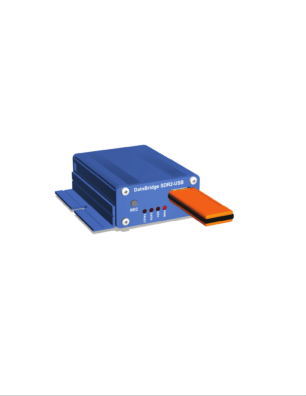
1.3 A quick guide to the DataBridge
SDR2-USB
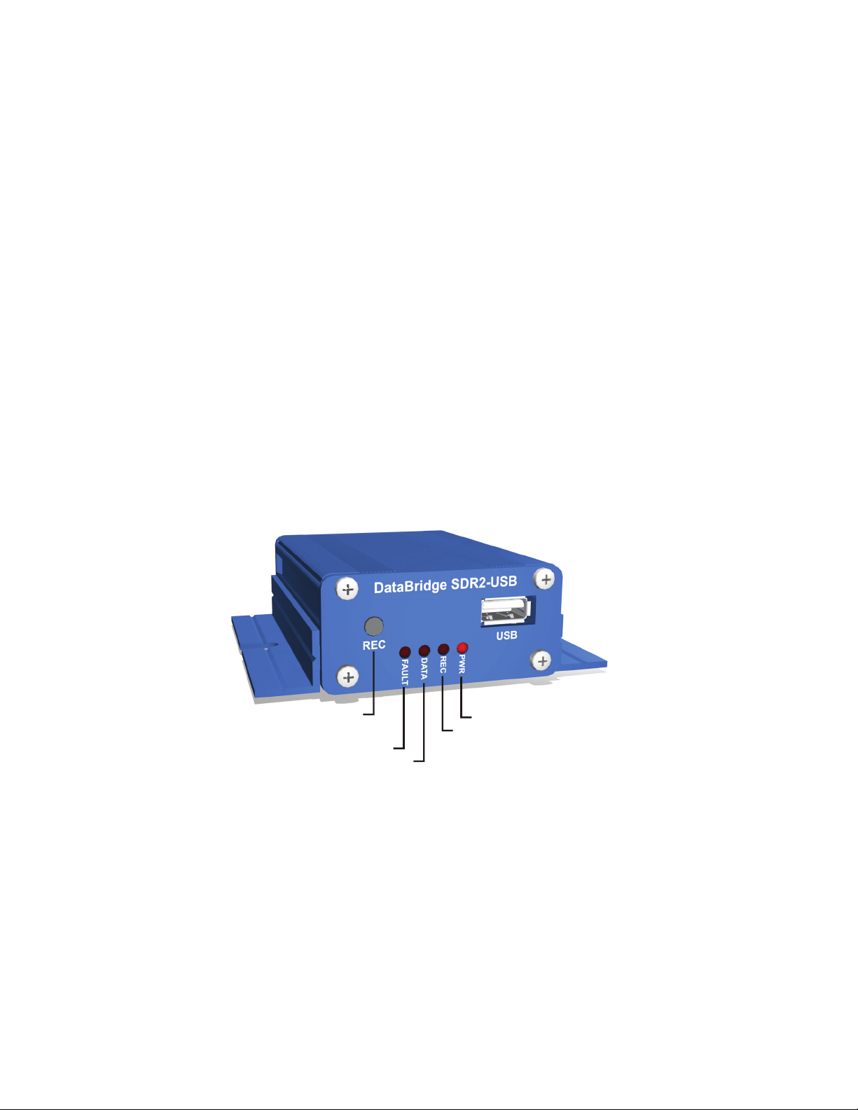
On the front of the SDR2-USB are the USB "A" socket, record button, and
LED indicators. The SDR2-USB can be toggled in and out of record mode
using the record button located on the front panel. The LED indicators
show the SDR2-USB’s current recording status. The data indicator flashes
when data is received and is used to verify data reception from your data
source.
6
Record Button
Fault Indicator
Data Indicator
Figure 1.1. SDR2-USB Front Panel Controls.
Power Indicator
Record Indicator
Page 9
SDR2-USB Configuration Guide rev 1.0 Getting Started
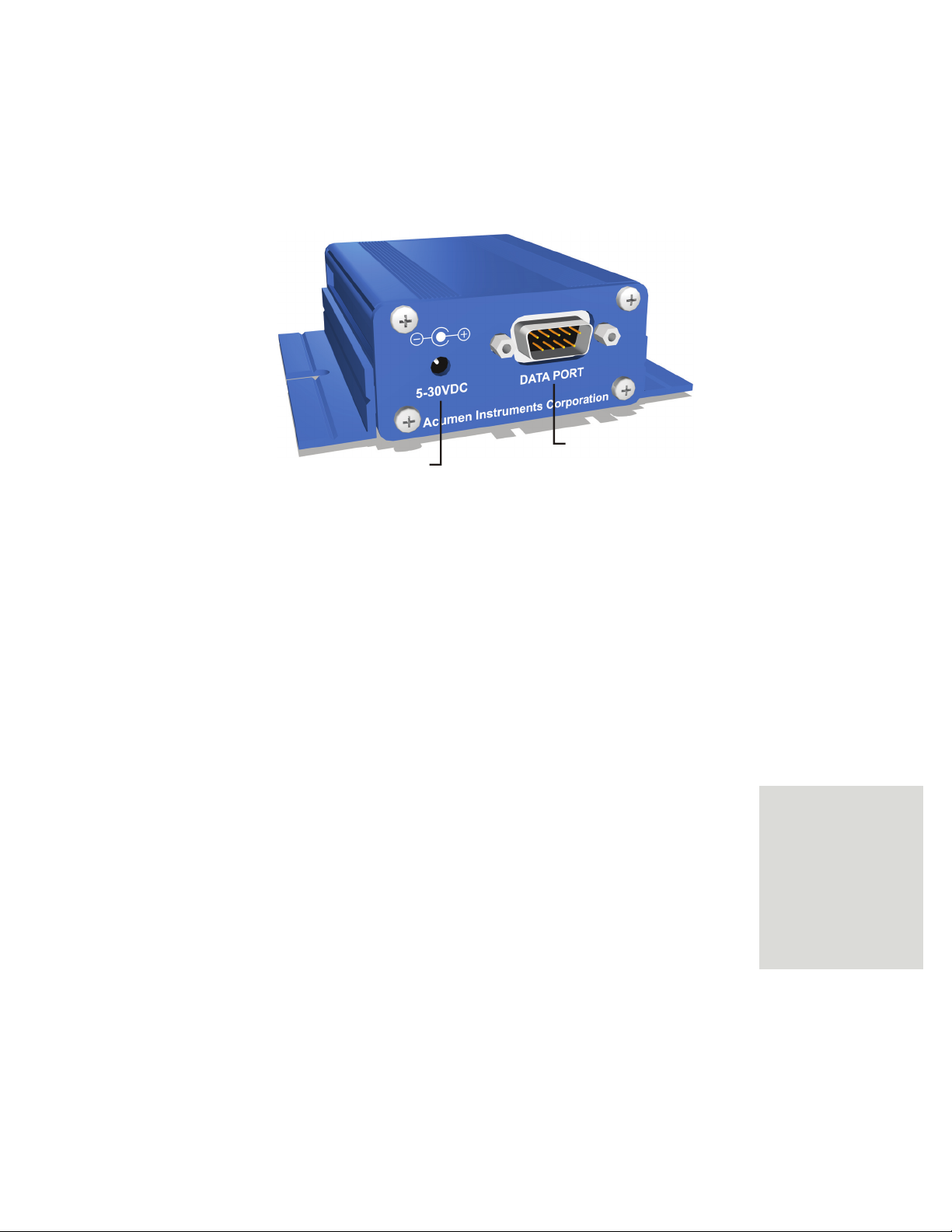
On the rear is the male nine-pin D-subminiature connector (DB9M) for the
data port. The 5 to 30 VDC power input is also located on the rear panel.
From serial data source
5 to 30 VDC Power
Figure 1.2. SDR2-USB Rear Panel.
1.4 Deploying the DataBridge SDR2-USB
1.4.1 Connecting power to your SDR2-USB
The SDR2-USB starter kit includes a 120VAC power supply that connects
via the rear panel. If you use an alternate power source, it should be capable
of sourcing at least 1W power. When you apply power the power indicator
should light and the other indicators should flash in sequence.
1.4.2 Configuring your SDR2-USB via the setup file
To successfully receive data from your data source, the SDR2-USB must
know at which baud rate the data source is transmitting. Configure the
recorder for this baud rate using the setup file.
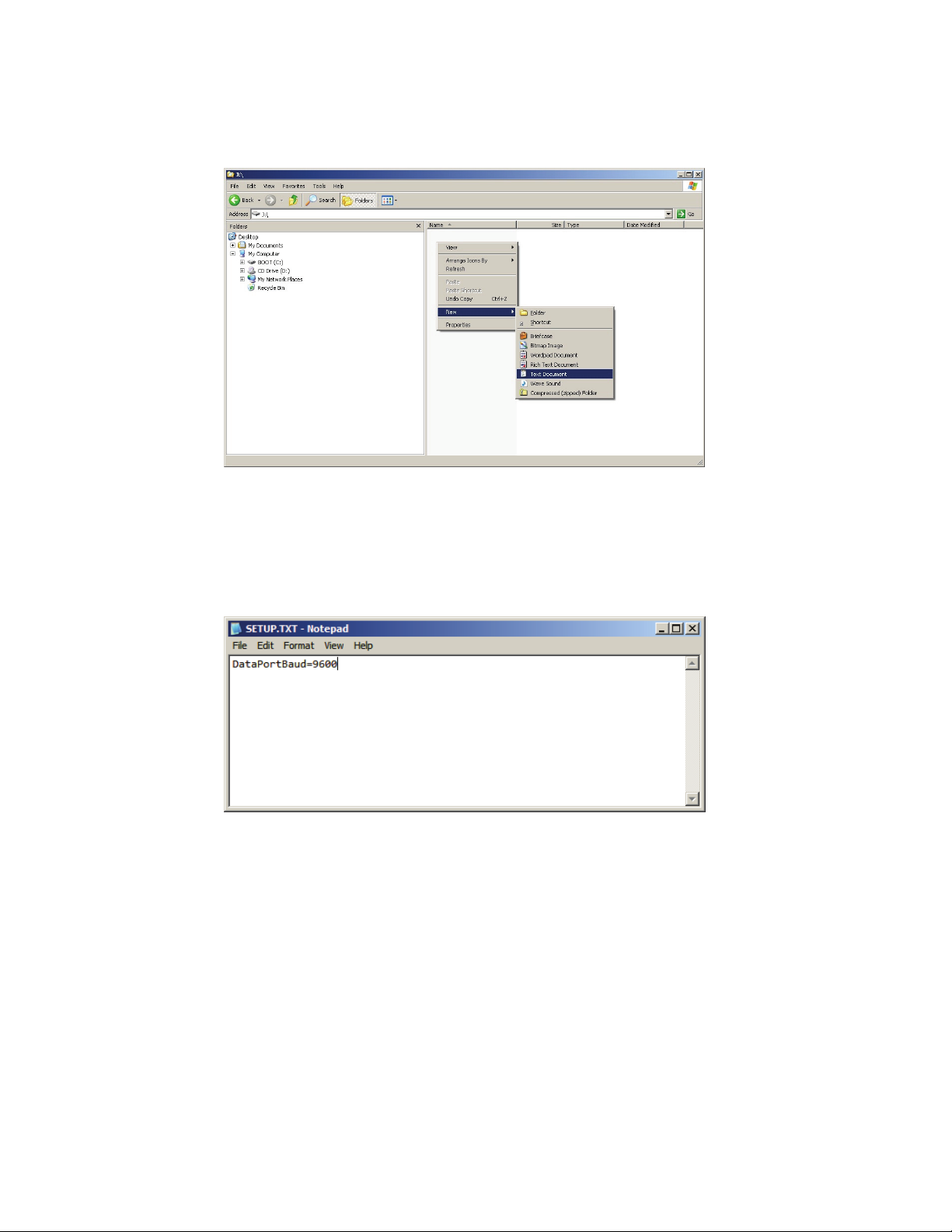
Insert the USB device you intend to use for recording into your PC’s USB
socket. Usually, Windows will respond by displaying the contents of the
device. If this doesn’t occur, navigate to the device’s drive letter (e.g. J:).
Right-click within your drive’s contents in Windows Explorer, then select
“New” and “Text Document.” When prompted, name the file setup.txt
(See Figure 1.3).
NOTE: Your
computer’s Windows
installation may
display different drive
letters, file types, etc.
due to differences in
Windows versions,
configurations, and
software installations.
7
Page 10
Getting Started SDR2-USB Configuration Guide rev 1.0
Figure 1.3. Creating setup.txt.
Once the file is created, double-click it to open the file in Windows Notepad
and enter “DataPortBaud=9600” as shown in Figure 1.4. This tells the
SDR2-USB to communicate with your data source at 9600 baud. The baud
rate for your serial data source may differ from 9600 bps.
Figure 1.4. Editing a simple setup.txt file.
Close Windows Notepad, then right-click the USB device’s drive letter and
click “Eject” to safely remove the device from your system.
Insert the USB device into the SDR2-USB, connect your serial data source
to the DB9M connector, and connect power. The SDR2-USB will display a
left-to-right-to-left flashing sequence. If your data source is outputting data,
the front panel “data” indicator will flash as data arrives.
1.4.3 Congratulations!
You’ve set up the SDR2-USB to communicate with your device!
8
Page 11

SDR2-USB Configuration Guide rev 1.0 Configuring the DataBridge SDR2-USB
2
2
Now that you’ve successfully edited the SDR2-USB’s setup.txt file, you are
ready to configure it for use with your serial data source. Using the setup
file, you can:
• Set the date and time.
• Configure handshaking and data word format for your device.
• Specify a directory to record files to.
• Specify a filename for recording.
• Select how and when data is written to files.
• Add time stamps to recorded files.
Before you begin, be sure you have the documentation available for the
device you’ll connect to your SDR2-USB. If possible, be sure you can
communicate with the data source using the supplied software and/or your
communications software. An intimate knowledge of your data source's
communications standards will make connecting it to the SDR2-USB
simple.
2. Configuring the
DataBridge
SDR2-USB
Note: all SDR2-USB settings are persistent. Changes made via the
setup file will be retained by the recorder after power is removed and
until they are reversed in the setup file or the recorder is restored to
factory defaults (see Section 3.4).
9
Page 12
Configuring the DataBridge SDR2-USB SDR2-USB Configuration Guide rev 1.0
2.1 Comments
Within the setup.txt file, it is useful to record comments documenting the
settings chosen and why some configuration choices were made. Comments
are also useful for temporarily disabling setting(s) for the purposes of testing
multiple settings.
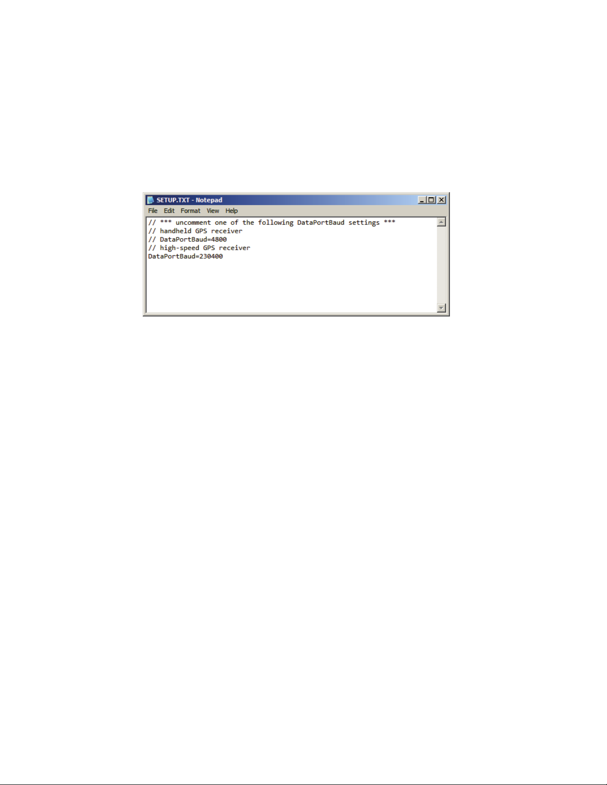
Figure 2.1. Use of comments to switch between GPS
receivers.
To create a comment line in the setup file, place to forward slashes (“//”) at
the beginning of a line. The SDR2-USB will completely ignore any line that
begins with //. To disable a particular line temporarily, insert // at the
beginning of the line.
2.2 Setting date and time
The SDR2-USB features a real-time clock that reports a file’s last modified
date and time. The real-time clock accurate and battery-backed, so setting
the date and time is seldom necessary.
Unlike DataBridge SDR products equipped with a configuration port,
setting the SDR2-USB’s date and time is a four-step process.
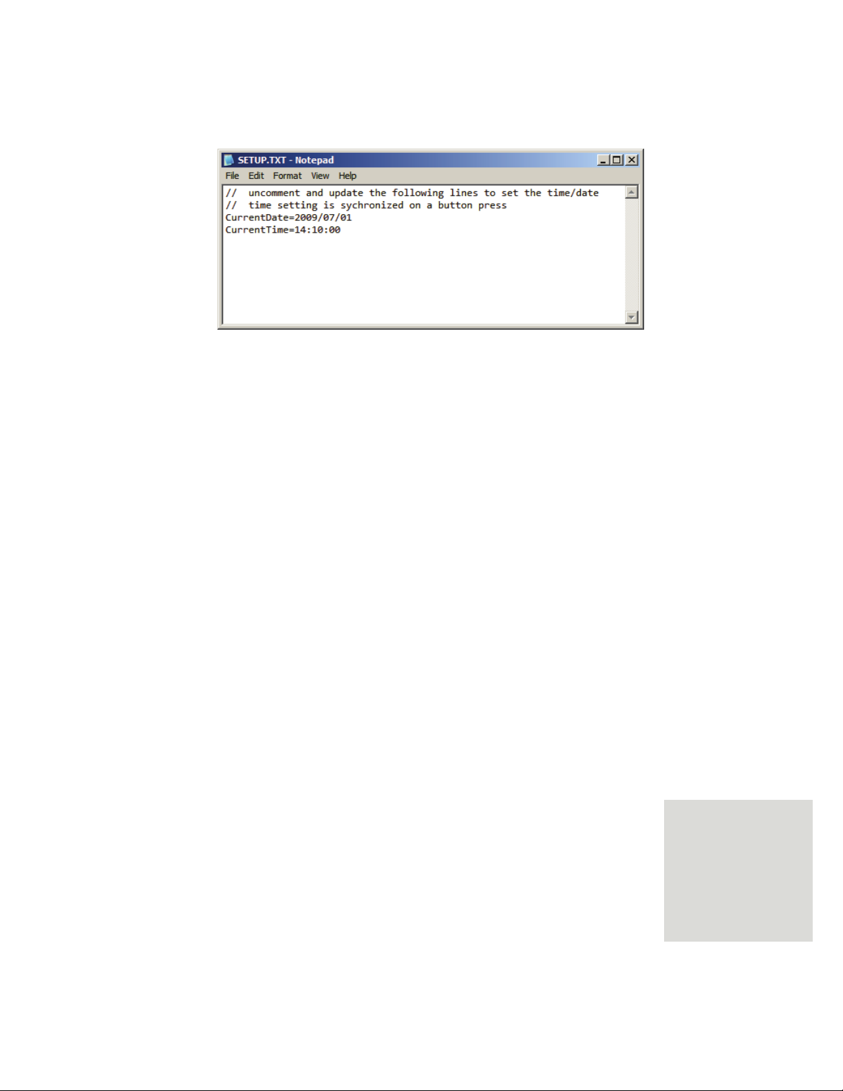
Step 1: Edit setup.txt
Add CurrentDate= and CurrentTime= lines to the setup file (see
Figure 2.2) with a time value 1-2 minutes ahead of the current time. The
year field must be specified using 4 digits, while all other fields must be
specified using 2 digits. Date is specified in YYYY/MM/DD format, and
time is entered using 24-hour format. Take note of this time for use in
step 3.
10
Page 13
SDR2-USB Configuration Guide rev 1.0 Configuring the DataBridge SDR2-USB
Figure 2.2. Setting date and time.
Step 2: Insert USB storage device and apply power
Eject the USB storage device and remove it from the computer. Insert the
USB device into the SDR2-USB, and connect power. The SDR2-USB will
display its usual flashing pattern, then read the setup file and turn on all 4
front-panel LED indicators. If precise setting is desired, monitor a
stopwatch or computer clock.
Step 3: Synchronize the SDR2-USB clock
When the stopwatch or computer clock reaches the time specified in step 1,
press the record button on the front panel. The SDR2-USB will the operate
normally.
Step 4: Re-edit setup.txt
Remove the USB storage device from the SDR2-USB and edit the setup file
using Windows Notepad on the PC. Disable the CurrentDate= and
CurrentTime= lines by inserting
// characters before them. These lines can
also be deleted if date/time setting will not be performed again.
2.3 Configuring the data port
Before the SDR2-USB and your data source can communicate, they must
interact at the same data rate and using the same data format.
The SDR2-USB's data port is, by default, configured to communicate at
115200 bps.
If your data source can communicate at 115200 bps (also referred to as
115200 baud), it may be easiest to configure it for 115200 bps. For devices
with a fixed data rate, you will need to set the SDR2-USB's data port baud
rate to match your data source. You may also wish to choose a higher data
rate and hardware handshaking if your data source sends a high volume of
data.
NOTE: By default,
the SDR2-USB uses a
serial data format of
eight data bits, no
parity, and one stop bit
(8N1). Most serial
devices use this
format.
11
Page 14

Configuring the DataBridge SDR2-USB SDR2-USB Configuration Guide rev 1.0
Hardware handshaking prevents a data source from sending data when the
SDR2-USB is not ready to receive it – the SDR2-USB can “shut off” the
transmitting data source if, for example, the USB storage media is slow or
not present.
Be sure that your serial data source and the SDR2-USB use the same
handshaking settings. If your data source monitors the handshaking signals
but the SDR2-USB doesn't send the appropriate signal, the software may
never transmit data.
To change the baud rate for the data port, add the line DataPortBaud= to
the setup file as in Figure 1.4. Common baud rates are 300, 1200, 2400,
4800, 9600, 19200, 38400, 57600, 115200, 230400 bps, although the
SDR2-USB can handle “nonstandard” baud rates as well.
To enable hardware handshaking, include the line DataPortHandshake= in
in the file, with a value of 1 for enabled or 0 for disabled.
Finally, while 8N1 communication is used by the vast majority of data
sources, some devices communicate using nonstandard data word formats
such as 7E1. To specify this, add the line DataPortWordFormat= to the
setup file, with a value of 8N1, 7E1, etc.
2.4 Specifying a filename and folder
By default, the SDR2-USB records data to a file called SDR-0000.DAT
located in the
keep this filename or specify a new filename that reflects the data it contains.
For example, you may wish to use
name like
Likewise, your choice of folder names may reflect something about the data
it contains.
Notes about filenames
When you specify a filename, it must conform to the FAT 8+3 filename
format. This means that files contain up to 8 characters, a period ("dot"), and
up to three more characters. For example, BRIDGE.DAT, ABCDEFGH.123,
and
1 are all valid filenames, while DATA.FILE, and JOHNSMITH.TXT are
not. The SDR2-USB ignores characters you type that are not allowed in
FAT16 filenames, such as: \/*|[]. Specifying illegal characters can
sometimes result in unpredictable filenames.
To specify the name of the file the SDR2-USB will use for recording data,
include the line Filename= in your setup file and specify a folder and
filename after the equals sign. For example, to record to a folder named
“GPSDATA” and use a filename of “GPS-0000.TXT”, include the line
Filename=GPSDATA\GPS-0000.TXT (see Figure 2.3).
DATA subfolder in the storage device's root directory. You can
PRESSURE.TXT for pressure data or a
TEMP1109.TXT for temperature data from November 2009.
12
Page 15

SDR2-USB Configuration Guide rev 1.0 Configuring the DataBridge SDR2-USB
Figure 2.3. Specifying filename and folder for recording.
2.5 Configuring file creation behavior
Be default, the SDR2-USB creates a new file in the recording folder every
time recording is initiated, generating a new, unique filename based on the
previous filename. To instruct the SDR2-USB to always append data to the
existing file when recording starts, add the line Append=1 to the setup file.
The SDR2-USB can also be configured to periodically restart recording
based on file size, a period of time in seconds, or at specific times of day.
Use the line Fileclose= to enable this periodic scheduled file closing, and
FileCloseBytes=, FileCloseSeconds=, or StartTime= and StopTime= to
enable one of these modes (see section 4.1.4 for more details).
Finally, the SDR2-USB can be configured to overwrite the oldest file found
in the recording directory if necessary. When this mode is enabled, the
SDR2-USB will delete the oldest file on the disk whenever recording starts
and the storage media has less than 1 megabyte of free disk space.
Use this option with scheduled file closing to configure the SDR2-USB as a
circular buffer that contains only the most recently received data. To enable
overwrite-oldest mode, include the line OverWriteOldest=1 in the setup
file.
2.6 Adding time stamps to recorded files
Along with file creation and last-modified dates, many users want to record
date and time information as data is received. Date and time stamps can be
logged along with incoming data and triggered either when a specific data
byte is received or when a gap in the data stream is detected.
Date/time stamping is commonly used for ASCII (human-readable) text
data. Lines of text end with a line feed character (ASCII code 10). Enable
the SDR2-USB’s time stamping feature by adding the line Timestamp=1 to
the setup file. Then, instruct the recorder to add a time stamp after a line
13
Page 16

Configuring the DataBridge SDR2-USB SDR2-USB Configuration Guide rev 1.0
feed is received by adding the line TimestampTrigger=10. The recorder will
be “armed” to time stamp when a line feed is received, then insert a stamp
when the next character is received— at the start of the next line.
It is common to encounter a data source that periodically outputs “bursts” of
data with time gaps between the bursts. For example, a GPS receiver
outputs a position report once/second, then sits idle between reports. For
this scenario, it is convenient to configure the recorder to insert a time stamp
after any gap in the data stream. To specify this behavior, add the line
TimeStampTrigger=gap to the setup file.
Custom time/date stamp formats are also available and can include
millisecond-precision stamping. See section 4.1.5 for more details on
custom date/time stamps.
2.7 Testing your configuration
To test your configuration, use a null modem adapter or cable to connect a
computer running terminal software (e.g. Windows HyperTerminal) to the
SDR2-USB’s data port. Your computer then becomes a data source.
Press the Record button to enter record mode. The SDR2-USB’s record
indicator will illuminate.
To ensure that recording is occurring, type several keystrokes on the
terminal or use the software’s ASCII text upload feature to send a text file.
The SDR2-USB’s data indicator should blink as you press keys, indicating
data is being received. When finished, press the record button again to stop
recording and inspect the file created on the USB storage device.
Note: The SDR2-USB will not echo data while it is being recorded, so you
will not see characters appear on-screen as you type. You can enable your
terminal software’s "local echo" or "full duplex" feature to view data as you
send it.
14
Page 17

SDR2-USB Configuration Guide rev 1.0 Operations
3
3
3.1 Setup file reading
3. Operations
The setup.txt file on the USB storage device is read only when power is
applied to the SDR2-USB. Once read, all settings found in setup.txt are
retained by the recorder.
3.2 Record mode operation
When you press the record button, the SDR2-USB searches for the current
file specified in the setup file, creates it if necessary, and opens it. Once the
SDR2-USB has successfully opened the file, the record indicator turns on
and the SDR2-USB enters record mode. Once in record mode, the SDR2USB records any data received on the data port to the open file.
3.2.1 Receiving data
The data indicator flashes when the SDR2-USB receives data. This indicator
is useful to ensure that the SDR2-USB is actually receiving data via the data
port. Note: this flashing indicator does not
Incorrect baud rates between the data source and SDR2-USB may still cause
the data indicator to flash and invalid data to be written to the current file.
guarantee a correct baud rate.
15
Page 18

Operations SDR2-USB Configuration Guide rev 1.0
g
A
g
3.2.2 Stopping recording
Incoming data is written to the open file as it is received until you stop
recording by pressing the record button. The SDR2-USB then closes the
file, updates its directory entry (recording file size, date, and time), and
returns to stop mode.
3.2.3 Device removal while recording
Do not terminate recording by removing the USB storage device without
stopping the recorder, or disk corruption may occur.
3.2.4 Power failure and improper shutdowns
If the SDR2-USB loses power while in record mode, it returns to record
mode after power is restored.
An improper shutdown may result in loss of data (due to sector buffering
and caching in the storage device) and minor allocation errors that can be
repaired using the Windows 95/98/NT/2000/XP/Vista™ Explorer or
chkdsk.exe from the Windows Command Prompt.
3.2.5 Filename generation
When operating with Append=0 (see section 4.1.3), unique new filenames
are generated based on the specified filename. This is done to avoid
overwriting an existing file within the specified folder.
Filenames are generated by “incrementing”. Before incrementing, the file’s
name is extended to 8 characters with a sequence of zeros. From there, the
filename’s last character is incremented through the digits 0-9 and A-Z,
carrying to the next-last as needed. An example of incrementing is shown in
Figure 3.1.
Before Incrementin
BRIDGE.DAT BRIDGE01.DAT
BRIDGE01.DAT BRIDGE02.DAT
BRIDGE09.DAT BRIDGE0A.DAT
BRIDGE0Z.DAT BRIDGE10.DAT
BRIDGE10.DAT BRIDGE11.DAT
Figure 3.1. Generating filenames when append mode is off.
fter Incrementin
3.2.6 Full storage media
When the storage media’s first valid partition is full, the SDR2-USB returns
to stop mode unless overwrite-oldest mode is enabled, in which case the
SDR2-USB will delete the oldest file in the target folder and return to
recording mode.
16
Page 19

SDR2-USB Configuration Guide rev 1.0 Operations
Delete files on the target media using your computer or replace the media,
then insert and press the record button to record data normally.
3.2.7 Formatting the storage media
If you have purchased a USB storage device, you may need to format it
using MS-DOS™, Windows 95/98/ME™, Windows NT/2000/XP™, or
another operating system that supports the FAT file system.
The SDR2-USB supports only the FAT and FAT32 file systems. If your
computer supports the NTFS, HPFS, or other advanced file systems, be
sure your card is formatted using FAT or FAT32.
NOTE: If your USB
storage media was
included with
SDR2-USB, it is
already formatted
properly.
Figure 3.2. Formatting a small USB memory key using the FAT
file system.
3.2.8 Partitions
In some cases, disks are partitioned to contain multiple "virtual" drives on a
single disk. Partitioning is sometimes done to overcome the 2 gigabyte size
limit in MS-DOS™ (and create multiple 2 gigabyte drives), support multiple
operating systems and file systems, or make more efficient use of disk space.
FDISK.EXE (included with MS-DOS™ and Windows 95/98™), Disk
Administrator (included with Windows NT/2000/XP/Vista™), Norton Disk
Doctor™, and Norton DiskEdit™ are useful tools for managing and
analyzing disk partitioning schemes.
The SDR2-USB supports both extended and primary FAT partitions, but
always reads and writes files in the first partition it recognizes as a FAT
partition.
17
Page 20

Operations SDR2-USB Configuration Guide rev 1.0
3.3 Lithium battery maintenance
The SDR2-USB's real-time clock uses a small lithium battery to maintain
time when external power is unavailable. The life of this battery should
exceed 5 years.
If you find your SDR2-USB is not keeping time correctly when power is lost,
you may need to replace the battery. If necessary, replace the battery with a
Panasonic CR2032, or equivalent, making sure the positive (+) face is in
contact with the battery clip. After replacing the battery, be sure to reset the
SDR2-USB’s time and date.
3.4 Resetting to factory defaults
The SDR2-USB can be reset to factory defaults by removing the USB
storage device, holding the record button, and connecting power. Once
power is connected, the record button must be held for 5 seconds until the
flashing pattern is displayed on the front panel LEDs.
Resetting to factory defaults overrides all settings that have been changed via
the setup file.
18
Page 21

SDR2-USB Configuration Guide rev 1.0 Setup File Reference
4
4
All SDR2-USB configuration is performed via the setup.txt file in the root
folder of the USB storage device. The setup file is read only when power is
connected to the SDR2-USB, and all settings specified within the setup file
are retained by the recorder indefinitely.
4. Setup File
Reference
4.1.1 Initial Setup Commands
The CurrentDate= and CurrentTime= setup file lines are used during onetime initial setup to set the real-time clock’s time and date values. After
including these lines in the setup file, power up the SDR2-USB and press
the record button to synchronize the clock, then re-edit the setup file,
erasing or commenting-out the lines for future use.
CurrentDate: Use this command to set the real-time clock’s date. Date
must be specified in YYYY/MM/DD format (e.g. 2009/06/30 for 30 June
2009).
CurrentTime: Use this command to set the real-time clock’s time. Time
must be specified in 24-hour HH:MM:SS format (e.g. 14:49:00 for 2:49
PM).
// uncomment and update these 2 lines to set the time
// time setting is synchronized on a button press
CurrentDate=2009/06/30
CurrentTime=14:49:00
19
Page 22

Setup File Reference SDR2-USB Configuration Guide rev 1.0
4.1.2 Data Port Setup Commands
DataPortBaud (default=9600): Use this setup file command to specify a
bits/second rate for communication with your data source. Industrystandard baud rates are 300, 1200, 2400, 4800, 9600, 19200, 38400, 57600,
115200, and 230400 bps. The SDR2-USB can also handle nonstandard
rates including 460800 and 961600 bps.
DataPortWordFormat (default=8N1): This command changes the
SDR2-USB’s data bits, parity, and stop bits. To specify the most common
setting, set this value to “8N1”, meaning eight data bits, no parity, and one
stop bit. Other possible values include seven data bits, odd/even parity
(O/E), and one or two stop bits, resulting in the following permutations:
8N1,8N2,7E1,7E2,7O1,7O2,8E1,8O1.
DataPortHandshake (default=0): Use this setup file command to turn
hardware handshaking on or off. When enabled, the SDR2-USB will drive
its RTS signal low when the USB media isn’t present and internal data
buffer space is exhausted. When disabled, the RTS signal will remain high
regardless of the SDR2-USB’s state.
// data port baud rate (50-921600)
DataPortBaud=9600
// data port word format (8 data bits, no parity, 1 stop bit)
DataPortWordFormat=8N1
// data port handshaking (0=off)
DataPortHandshake=0
4.1.3 Recording Behavior Commands
Filename (default=DATA\SDR-0000.DAT): The Filename command sets
both the location and name of the file to be recorded. To specify a folder
for data storage (recommended), precede the filename with a folder name
and backslash. To record files to the media’s root folder, simply specify a
filename. The SDR2-USB uses this filename for the first file that’s
recorded— subsequent files are given unique names based on this name.
Append (default=0): Use the Append command to control whether the
SDR2-USB creates new files each time recording restarts. When
Append=1, the SDR2-USB adds data to the existing file. When
Append=0, the SDR2-USB creates a new file with unique filename any time
recording starts (see section 3.2.5).
FlushBuffer (default=0): Use the FlushBuffer command with a value of 1 to
configure the SDR2-USB to record only data that is received after recording
starts. When FlushBuffer is 0, the recorder can buffer several seconds of
data while recording is stopped, allowing time to exchange media if needed.
ForceRecording (default=0): ForceRecording=1 configures the SDR2-USB
to always record if storage media is present and ignore the front-panel
button. This setting is useful for guaranteeing data is recorded.
OverWriteOldest (default=0): Use OverWriteOldest=1 to configure the
SDR2-USB to overwrite the oldest file in the destination recording folder if
20
Page 23

SDR2-USB Configuration Guide rev 1.0 Setup File Reference
possible when space available on the storage media is exhausted. Together
with scheduled file closing, this option can be used to configure the
SDR2-USB as a circular buffer— as the disk fills, the oldest file is
overwritten.
// file name and path to record to
Filename=DATA\GPS0000.txt
// create new files when recording starts
Append=0
// buffer data when stopped
FlushBuffer=0
// always record if media is present
ForceRecording=1
// overwrite oldest file if necessary
OverWriteOldest=1
4.1.4 Scheduled File Closing Commands
Scheduled file closing, together with Append=0, allows the user to divide
recorded data into files of a more manageable size.
FileClose (default=0): The FileClose setup file line enables and disables
scheduled file closing.
FileCloseSeconds: The FileCloseSeconds setting configures the SDR2-USB
to close the current file and restart recording after the specified number of
seconds. For example, to configure the recorder to restart recording every
hour, use FileCloseSeconds=3600 (3600 seconds=60 minutes=1 hour).
FileCloseBytes: The FileCloseBytes setup file line configures the recorder to
close the current file and restart recording once the current file reaches the
specified number of bytes. For example, use FileCloseBytes=1048576 to
configure the SDR2-USB to create a new file if the size reaches 1 megabyte.
StartTime, StopTime: The StartTime and StopTime lines configure the
recorder to start and stop at specific times of day (specified in 24-hour
HH:MM:SS format). If start and stop times are equal, each file will contain
24 hours of data. FlushBuffer=1 (see above) is usually used if start and stop
times are different in order to reject data received while recording was
stopped.
// enable scheduled file closing
FileClose=1
// record only during business hours
StartTime=08:00:00
StopTime=17:00:00
FlushBuffer=1
4.1.5 Time Stamping Commands
The SDR2-USB can insert time and date information into files during
recording. Among other things, this is useful for scientific data analysis and
historical trending studies.
Timestamp (default=0): The Timestamp setup file line enables date/time
stamping.
21
Page 24

Setup File Reference SDR2-USB Configuration Guide rev 1.0
TimestampTrigger: The TimestampTrigger setup file line specifies a decimal
ASCII character that “arms” the time stamping function. Once the trigger
character is received, the recorder will insert a time stamp when the next
byte of data is received. For example, a trigger value of 10 will configure the
SDR2-USB to insert a time stamp after a line feed is received.
TimestampTrigger=gap: Specifying a trigger value of “gap” enables a special
time stamping mode where the SDR2-USB will detect time gaps in the
stream of incoming serial characters and insert a time stamp after the gap.
This is useful for data sources such as GPS receivers that output “bursts” of
data periodically.
TimestampFormat (default=MM/DD/YYYY hh:mm:ss\20): Use the
TimestampFormat command to provide a template for the timestamps as
they are inserted into the file. Timestamp field format values are casesensitive— month, day, and year fields must be specified in capital letters,
while hour, minute, second, and millisecond fields must be provided in
lower-case letters. Escape codes are used to insert characters such as spaces,
line feeds, carriage returns, and tabs. To include an escape sequence, use a
backslash followed by the two-digit hexadecimal ASCII code for the
character to use (e.g. \0A for a line feed or \20 for a space).
// enabled time stamping
Timestamp=1
// trigger on a line feed
TimestampTrigger=10
// include milliseconds and 2-digit year in time/date stamp
TimestampFormat=MM/DD/YY hh:mm:ss.ddd\20
4.1.6 Other Commands
DisableIndicators (default=0): Use a setup file line with
DisableIndicators=1 to turn front-panel LED indicators off. When
enabled, the indicators will flash occasionally in a “heartbeat” pattern. Use
this setting to save small amount of power and/or avoid user confusion.
22
Page 25

SDR2-USB Configuration Guide rev 1.0 J4 Remote Control Port
5
5
5. J4 Remote
Control Port
5.1 Overview
The SDR2-USB’s J4 remote connector allows for starting and stopping
recording via external switches/buttons or TTL/CMOS digital logic. The J4
connector also provides alternate outputs for the front-panel fault, data, and
record indicators.
5.2 Location
The J4 connector is located next to the J1 power input connector on the
SDR2-USB’s internal circuit board.
23
Page 26

Setup File Reference SDR2-USB Configuration Guide rev 1.0
5.3 Functions
Table 5.1 describes the functions of the J4 remote connector.
VDD (3.3VDC) Regulated low-current voltage output. Use for deasserting
active-low inputs and driving LED indicator outputs.
GND (0 VDC) Signal ground. Use for asserting active-low inputs.
Momentary record input. Function is similar to front-panel
REC_BUTTON
Force-record input. To use, connect a toggle switch
REC_TOGGLE
Fault condition indicator output. Function is similar to the
FAULT
Data indicator output. Function is similar to the front-panel
DATA
Recording indicator output. Function is similar to the frontRECORD
record button. To use, connect a momentary pushbutton
switch between this contact and GND.
between this contact and GND. When closed, the
SDR2-USB will always enter record mode.
front-panel Fault indicator. When low, indicates an
unrecoverable error has occurred in the SDR2-USB. To
use, connect an LED’s cathode to this contact and its anode
to V
via a current-limiting resistor. Limit current to 10 mA
DD
max.
Data indicator. Pulses momentarily low to indicate data
reception in the SDR2-USB. To use, connect an LED’s
cathode to this contact and its anode to V
limiting resistor. Limit current to 10 mA max.
panel Record indicator. Driven low when the SDR2-USB is
recording data to an open file. To use, connect an LED’s
cathode to this contact and its anode to V
limiting resistor. Limit current to 10 mA max.
via a current-
DD
via a current-
DD
Table 5.1. J4 remote control port pin functions.
5.4 Pinout and Mating Cable
The J4 connector is a 2mm 10-pin connector housing that mates to a Hirose
DF11-10DS-2C shell (Digi-Key part number H2023-ND). A pre-built J4
cable is available from Acumen Instruments Corporation on request.
24
Page 27

SDR2-USB Configuration Guide rev 1.0 J4 Remote Control Port
Contact Function Direction Wire Color
1 VDD (3.3 VDC) -
2
3
4 input Grey
5
6 no connect -
7
8 output Green
9 VDD (3.3 VDC) -
10 GND (0 VDC) -
Table 5.2. J4 remote control port pinout.
GND (0 VDC)
REC_BUTTON
REC_TOGGLE
FAULT
DATA
RECORD
Black
input Blue
output Yellow
output Orange
J4 mating plug (shell): Hirose DF11-10DS-2C (Digi-Key part number
H2023-ND)
For use with DF11 crimp contacts e.g. DF11-2428SCA (Digi-Key part number
H2300-ND) or pre-crimped wires (Digi-Key part number H3BXG-101LL-CW
where LL=length in inches, C=color code, W=wire gauge code).
5.5 Force-Record Shunt Installation
The SDR2-USB can be forced into record mode any time power is applied
and USB storage is present. To use this mode, install a 2mm shunt between
J4 pins 4 (REC_TOGGLE) and pin 2 (GND).
A good choice of shunt is Norcomp part number 810-002-SP2L001 (DigiKey part number SP2-001E-ND).
25
Page 28

Page 29

SDR2-USB Configuration Guide rev 1.0 Service and Support
6
6
6. Service and
Support
6.1 Exception Codes
The following are common error codes encountered when using DataBridge
SDR2-USB products. To determine which error has occurred, watch the
"exception" indicator on the SDR2-USB's front panel and count the number
of rapid blinks. Each sequence is separated by a 1 second pause in the blink
pattern.
Exception 2: Root Directory Full
A FAT (FAT16) root directory can have only 512 directory entries (fewer if
long filenames are used). Delete files from the root directory, record to a
subfolder in the root directory, or use FAT32 formatting to overcome this
limitation.
Exception 3: Disk Full
The disk has no (or almost no) available space for files. Delete files from the
disk to ensure space is available.
27
Page 30

Service and Support SDR2-USB Configuration Guide rev 1.0
Exception 4: Bad Boot Record
Occurs when the disk is completely unformatted or formatted for an
unsupported file system.
Use format /FS:FAT from the Windows command prompt to ensure
proper FAT formatting.
Exception 5: Hardware Error
Usually occurs when the SDR2-USB cannot reset the USB storage device.
Try ejecting and reinserting the card or using a new card and contact
Acumen if problem persists.
Exception 6: EEPROM Error
Rare hardware error. Contact Acumen to discuss repair or replacement.
Exception 7: Cache Error
Rare hardware error. Contact Acumen to discuss repair or replacement.
Exception 8: Buffer Error (firmware error)
Rare error that may occur in customized or beta firmware versions. Contact
Acumen to report.
Exception 9: Tasking Error (firmware error)
Rare error that may occur in customized or beta firmware versions. Contact
Acumen to report.
Exception 10: USB Error
The USB storage media has reported a fatal error to the SDR2-USB.
Reinsert/replace the media and contact Acumen if problem persists.
Exception 11: Directory Creation Error
Rare. The SDR2-USB cannot create the subdirectory files are to be
recorded to. Try using a different directory name or reformatting the media.
Exception 12: FAT12 File System Detected
The SDR2-USB has determined that the USB media was formatted using
the FAT12 file system, which is unsupported. Reformat the USB storage
device using the /A:512 option (Windows 2000/XP) and retry.
28
Page 31

SDR2-USB Configuration Guide rev 1.0 Service and Support
6.2 Contacting Acumen Instruments
Corporation
6.2.1 Technical support
Service and technical support can be reached between the hours of 9
PM (Central Standard Time) Monday through Friday. Acumen Instruments
5
Corporation can be reached at the following phone numbers:
(515) 296-5366 (voice)
(515) 296-3554 (fax)
6.2.2 U.S. Mail
Acumen Instruments Corporation can be reached by mail at:
Acumen Instruments Corporation
2625 N. Loop Drive Suite 2200
Ames, IA 50010
USA
6.2.3 E-mail
Acumen Instruments Corporation can be reached via e-mail at:
info@acumeninstruments.com
6.2.4 World Wide Web
Acumen Instruments Corporation maintains a web site containing product
information and downloads:
AM and
http://www.acumeninstruments.com
6.3 Returning Equipment
Before returning equipment to Acumen Instruments Corporation, please call
for an RMA number and shipping information. This allows us to plan for
your shipment in order to provide the best possible service. When returning
equipment, please include a note indicating the symptoms of the failure and
any other pertinent information.
29
Page 32

Service and Support SDR2-USB Configuration Guide rev 1.0
6.4 Warranty
6.4.1 One year warranty
Acumen Instruments Corporation warrants this product to be free from
defects in materials and workmanship for a period of one (1) year from the
date of shipment. During the warranty period, Acumen Instruments
Corporation will, at its option, either repair or replace products that prove to
be defective.
6.4.2 Exclusions
This warranty shall not apply to any defect, failure or damage caused by
misuse, abuse, improper application, alteration, accident, disaster,
negligence, use outside of the environmental specifications, improper or
inadequate maintenance, or incorrect repair or servicing not performed or
authorized by Acumen Instruments Corporation.
6.4.3 Limitations
CUMEN INSTRUMENTS CORPORATION SHALL IN NO EVENT HAVE
A
OBLIGATIONS OR LIABILITIES TO BUYER OR ANY OTHER PERSON FOR LOSS
OF PROFITS
DAMAGES
NEGLIGENCE
ACTION
OF THE POSSIBILITY THEREOF
THE SALE
, LOSS OF USE OR INCIDENTAL, SPECIAL, OR CONSEQUENTIAL
, WHETHER BASED ON CONTRACT, TORT (INCLUDING
), STRICT LIABILITY, OR ANY OTHER THEORY OR FORM OF
, EVEN IF ACUMEN INSTRUMENTS CORPORATION HAS BEEN ADVISED
, ARISING OUT OF OR IN CONNECTION WITH
, DELIVERY, USE, REPAIR, OR PERFORMANCE OF THIS PRODUCT
(INCLUDING EQUIPMENT, DOCUMENTATION AND SOFTWARE). IN NO EVENT
SHALL THE LIABILITY OF
CONNECTION WITH ANY PRODUCT EXCEED THE ACTUAL AMOUNT PAID FOR
SUCH A PRODUCT
T
HIS WARRANTY IS IN LIEU OF ALL OTHER WARRANTIES, WRITTEN OR ORAL,
EXPRESSED OR IMPLIED
MERCHANTABILITY OR FITNESS FOR A PARTICULAR PURPOSE
ACUMEN INSTRUMENTS CORPORATION ARISING IN
.
, INCLUDING IMPLIED WARRANTIES OR
.
30
Page 33

SDR2-USB Configuration Guide rev 1.0 Serial Port Basics
A
A
A.1 Serial specifications
A.Serial Port
Basics
Serial data is any data that is sent one bit at a time using a single electrical
signal. In contrast, parallel data is sent 8, 16, 32, or even 64 bits at a time
using a signal line for each bit. Data that is sent without the use of a master
clock is said to be asynchronous serial data.
Several communications standards exist for the transfer of asynchronous
serial data. Common PC’s transfer data using the EIA RS-232C (also known
as V.28 or V.24). Updated versions of this standard include RS-232D and
EIA/TIA-232E, but most literature still refers to the RS-232C or RS-232
standard.
Other asynchronous serial standards in common use include RS-422, RS423, and RS-485. These standards allow higher data rates and longer cable
lengths than RS-232 and are common in industrial settings.
A.2 Data rates
The baud rate for a serial connection is the number of bits that are
transmitted per second. It is specified in bits/second or baud. For example, a
9600 baud serial link transfers 9600 bits per second.
31
Page 34

Serial Port Basics SDR2-USB Configuration Guide rev 1.0
The EIA RS-232C standard permits data rates up to 19200 bps and cable
lengths up to 400 meters (but not both).
data rate maximum distance
(bps) (meters) (feet)
19200 15 45
9600 25 76
4800 50 152
2400 100 304
1200 200 608
600 400 1216
Table A.1. Data rates and distances for RS-232 communications.
Although the specification only defines rates up to 19200 bps,
communication using data rates as high as 230400 bps and a short (<2
meter) cable are common. Standard modems communicate with computers
at up to 115200 bps.
As you may have guessed, the use of high baud rates requires more capable
computer hardware. At high baud rates, a computer must process as many as
23000 characters per second. The constant attention a computer must pay to
its serial port makes this problematic particularly in multitasking
environments such as Microsoft Windows 3.1/95/98/NT/2000.
A.2.1 Data rates and the UART
Computer hardware designers solve this problem by allowing the computer
to respond to characters less frequently. A Universal Asynchronous
Receiver/Transmitter (UART), the component responsible for
communicating via RS-232, may contain several bytes of memory called a
FIFO (first-in, first-out memory).
The original IBM PC (and many of its successors) used the 8250 UART,
which contained no FIFO. That is, a computer with 8250 (or 16450)
UART’s must respond to every incoming character.
Newer PC’s incorporate the 16550 UART or a variant. The 16550
incorporates a 16-byte FIFO and is mandatory for communications at
speeds above 9600 bps and is important for error-free communications at
lower speeds as well.
You can find out which type of UART’s your computer uses by using the
MSD.EXE tool provided with DOS and Windows or by looking in the
Windows 95/98 control panel.
A.3 More asynchronous serial parameters
In most cases, the data rate in bytes/second can be approximated by dividing
the baud rate (in bits/second) by 10. If a byte consists of 8 bits, why divide
by 10?
32
Page 35

SDR2-USB Configuration Guide rev 1.0 Serial Port Basics
To transfer data asynchronously, the UART frames the 8 data bits between a
stop bit and a start bit. The start bit is always a zero, while the stop bit is
always a one. So, a byte of data sent serially is made up of 10 bits instead of
the usual 8.
Asynchronous serial devices can communicate using 7 or 8 data bits, and 1,
1½, or 2 stop bits. To further complicate matters, devices can also employ a
parity bit instead of an eighth data bit to check for errors. Even parity
systems transmit a one when the sum of the seven bits is an even number,
while odd parity systems transmit a one when the sum is odd. Still more
exotic systems may specify “mark” or “space” parity, where the parity bit is
always a one or zero, respectively.
What does all of this mean? Device vendors usually specify their data rate
and format using statements like “9600, 8N1”, which translates to 9600 bps,
8 data bits, no parity, and 1 stop bit or “19200, 7E1”, which translates to
19200 bps, 7 data bits, even parity, and 1 stop bit.
A.3.2 DTE and DCE
The RS-232 specification defines two classes of devices: data terminal
equipment (DTE) and data communication equipment (DCE). Your
computer’s serial port is configured for DTE operation, since the computer
acts as a terminal. Modems and many other serial devices are configured as
DCE, since they are communications equipment.
What’s the difference? A DTE device’s TD signal means “I transmit data on
this line.” A DCE’s TD signal can be read “You (the DTE) transmit data to
me on this line.” A DTE’s RD signal means “I receive data on this signal
line.” A DCE’s RD line means, “You, the DTE, will receive the data I
transmit on this signal line.” Sound confusing?
A look at a the DB9 connector pinouts and signal direction with respect to
DTE (e.g. your computer) makes things a little more clear.
signal name
transmitted data
received data
request to send
clear to send
data terminal ready
data set ready
data carrier detect
ring indicator
signal ground
Table A.2. Pinouts for 9-pin and 25-pin serial connectors.
TD
RD
RTS
CTS
DTR
DSR
DCD
RI
GND
pin number
25-pin 9-pin direction
2 3 DTE→DCE
3 2 DTE←DCE
4 7 DTE→DCE
5 8 DTE←DCE
20 4 DTE→DCE
6 6 DTE←DCE
8 1 DTE←DCE
22 9 DTE←DCE
7 5
NOTE: Most serial
devices format of eight
data bits, no parity,
and one stop bit
(8N1).
The cable that connects DTE devices (such as your computer) and DCE
devices (such as your modem) is simple. It connects the TD pin to TD, pin
RD to RD, etc. A cable that connects DTE to DTE or DCE to DCE must
connect the TD to RD and RD to TD. This cable is referred to as a null
33
Page 36

Serial Port Basics SDR2-USB Configuration Guide rev 1.0
modem cable because it can connect two terminals (DTE’s) without the use
of modems (DCE’s). Note that GND pins are always connected.
Most devices have female connectors (DB9 or DB25) if they are configured
for DCE operation and male connectors if they are configured for DTE
operation, but this is not always the case.
There is a simple trick for determining whether a device is DTE or DCE.
Connect a voltmeter’s ground line to the connector’s GND pin. Then, probe
the voltage on the TD and RD pins. If the TD pin voltage is small (3V<Vin<+3V), the device is configured to receive data on the TD pin, and
thus is a DCE device. Likewise, if the RD pin voltage is small, the device is
receiving data on the RD pin, and thus is DTE.
A.3.3 Handshaking
Handshaking signals by the receiving device to tell the transmitter “I am
ready for data” or “I am not ready for data.” These signals are optional: the
receiver may always be ready for data or may choose to simply discard data it
couldn’t process.
A DTE device asserts the “request to send” (RTS) signal when it is ready to
receive data and deasserts it when it cannot accept data. Likewise, a DCE
device asserts “clear to send” (CTS) when it is ready to receive data. The
RTS and CTS signals form a handshaking pair, and their use constitutes
RTS/CTS handshaking.
The “data terminal ready” (DTR) signal, asserted by the DTE, and the “data
set ready” (DSR) signal, asserted by the DCE serve similar functions and
constitute DTR/DSR handshaking. A DTE or DCE devices may employ
either or both forms of handshaking. Often, deasserting RTS or CTS signals
“micro” events, such as a buffer that is full but will be empty soon, while
deasserting DTR or DSR may signal “major” events such as that power has
not been applied.
RTS/CTS handshaking and DTR/DSR handshaking are both referred to as
hardware handshaking. Another form of handshaking, XON/XOFF or
software handshaking, requires that the receiver send a character (Control-S,
ASCII 19) to halt data transfer and another character (Control-Q, ASCII
17) to resume transfer. Although this method eliminates the need for the
RTS, CTS, DTR, or DSR signals, it suffers from slow response time by the
receiver and renders 2 characters of the 256-character ASCII set unusable.
A.3.4 Voltage levels
For noise immunity and long cable lengths, RS-232 devices convert
TTL/CMOS-level signals (0V=logic zero, +5V or +3.3V=logic one) to
higher voltage bipolar signals. For the TD and RD signal lines, RS-232
devices use a voltage between –3V and –25V to transmit a one and a voltage
between +3V and +25V to transmit a zero. For the other signal lines (RTS,
34
Page 37

SDR2-USB Configuration Guide rev 1.0 Serial Port Basics
CTS, etc.), RS-232 devices use +3V to +25V to assert the signal and –3V to
–25V to deassert the signal. These voltage levels are defined in the EIA/TIA232E specification. So, when a DTE devices drives RTS at –9.50V, it is
signaling the DCE to stop sending data.
A few devices, particularly devices that communicate at low data rates or
over short cables, bypass the voltage conversion altogether. These devices
often require “computer interface kits” that are really no more than a level
converter in a box. These serial ports are often referred to as TTL RS-232,
CMOS RS-232, or 5 Volt RS-232 ports and require level converters to
interact with computers and other serial devices.
35
Page 38

Page 39

Specifications SDR2-USB Configuration Guide rev 1.0
B
B
B.Specifications
B.1 Electrical specifications
SDR2-USB requires a 5 to 30 VDC power source power source via
connectors J7 and J1 on SDR2-USB. J1 is inaccessible on the SDR2-USB
without removing the enclosure.
Recording Mode +12 VDC
Idle +12 VDC
Table B.1. DataBridge SDR2-USB power consumption with
Kingston 1GB USB flash key installed.
B.1.5 J7 rear power receptacle pin configuration
pin Function
tip +5 to +30 VDC
ring Ground
Table B.2. The SDR2-USB rear power receptacle pin configuration.
see data
sheet
NOTE: The
SDR2-USB datasheet
contains further
specifications. All
specifications shown in
this section may be
superseded by the
datasheet.
37
Page 40

Specifications SDR2-USB Configuration Guide rev 1.0
B.1.6 J1 power receptacle pin configuration
pin Function
1 +5.0 to +30 VDC
2 Ground
Table B.3. The SDR2-USB internal power receptacle pin
configuration.
B.2 Serial communications
Serial Port
electrical interface compliance EIA/TIA-232E and V.28
data rates 50 to 921600 baud
data bits 7 or 8
stop bits 1 or 2
Parity None, even, odd
Handshaking RTS/CTS, none
Table B.4. Serial communications specifications for the
SDR2-USB.
B.3 USB socket
Socket Type USB "A" receptacle
storage capacity limited only by storage device and file system
Table B.5. USB socket specifications for the SDR2-USB.
B.4 Mechanical Specifications
SDR2-USB
Dimensions 3.35" L x 3.76" W x 1.18" H
(85 mm x 96 mm x 30 mm)
Weight (without USB media) 8.0 oz (225.0 grams)
Enclosure Material Aluminum extrusion
Table B.1. SDR2-USB mechanical specifications.
38
Page 41

Specifications SDR2-USB Configuration Guide rev 1.0
Notes:
39
 Loading...