

AC&T System ETOS-100XP-S04, ETOS-100XP-E40, ETOS-100XP-E22, ETOS-100XP-S22, ETOS-150XP-E40 User Manual
...Page 1

Industrial Network Server ETOS- XP Series
ETOS-XP SERIES
USER’S GUIDE
AC&T System Co., Ltd.
2017-06
Revision 1.1
-1-
Page 2
Device Type
User Instruction
Class A Devices
(Commercial Broadcasting
Communication Devices)
This is a device for commercial use (Class A) that is
registered for electromagnetic wave conformity, so sellers/
users must pay attention to this point.
Danger
If improper handling may result in a hazardous situation or possible death or
serious injury.
Precaution
If improper handling may result in a hazardous situation, moderate injury or
minor injury or material damage only.
Dangers
When working for communication cable, keep a distance of at least 100mm away from the power
supply cable.
Please pay attention to the rated power supply for each product. In particular, for the
products that receive DC 24V input, be sure to enter DC 24V in consideration of (+) and
(-) polarity. Inputting AC power supply may cause breakdown.
If power supply of the product is AC, be sure to use the grounded power supply.
Do not use any products that are damaged or deformed during opening. It may cause breakdown
of the product.
Do not drop or give a shock to the product. It may cause damage or breakdown of the product.
Please keep and use the products under the environmental conditions described in this
manual. In particular, it may cause breakdowns in environments where vibration, dust,
corrosive gas or dew may form. Therefore, use in the environment within the specified
dimensions.
When working on the communication cable, make sure to know the pin layout diagram in this
manual before wiring. For the other party’s devices to where ETOS-XP products and
communication line will be connected, thoroughly examine the contents of the communication
line beforehand before operation.
Dispose of the products as industrial waste.
The manufacturer shall not be liable for the accidents generated because of
not learning the “Dangers” and “Precautions” properly.
!!! PRECAUTIONS!!!
(Please read it before using)
When using the ETOS-XP series, please read this manual and the relevant manuals introduced in
this manual, and handle devices correctly paying attention to safety.
The precautions described in this manual are only for the ETOS-XP series.
[Instructions for Commercial (Class A) Device]
Safety precautions are classified into "Danger" and "Precaution".
Note that even those items listed in the "Precaution" may lead to serious consequences (dangers)
depending on the situation. Please be sure to observe the safety precautions since all of them
are important contents to keep.
In order to use ETOS-XP products efficiently and safely, please read and understand the following
contents before use.
The contents describe the installation of the product, wiring and operating environment and the
risks and precautions for disposal.
[Normal]
- 2 -
Page 3

Use the radio or mobile phone at least 30 cm away from the product. Otherwise, a
breakdown may occur.
Danger
For control lines or communication cables, do not wire them together with main circuit or
power lines. Wiring must be done 100 mm or more away from them.
When controlling the ETOS-XP series that is connected to a peripheral device, make sure that
the whole system operates safely at all times. In addition, be sure to read the manual
carefully and check safety before operating the ETOS-XP series. Especially, in the case of
controlling remote ETOS-XP series from an external device, it may not be possible to respond
immediately to troubles of ETOS-XP series due to data communication error. In the case of
data communication error, provide system-level countermeasures between external devices and
ETOS-XP series.
Precaution
Use the ETOS-XP Series in the environment of the general specifications described in this
manual. Otherwise, electric shock, fire, breakdown, damage to the product or burn may
occur.
Mount ETOS-XP series correctly when installing them. Failure to properly install the module
may cause breakdown, failure or dropping.
Be sure to shut off the power supply from the outside before installing or removing the
module (card). Failure to do so may result in electric shock or damage to the product.
Do not directly touch the conductive parts or electronic components of the module. It may
cause malfunction or breakdown of the device
If there is a lot of vibration in the installation environment, please do not allow the
vibration to directly affect the product. It may cause electric shock, fire or breakdown.
Do not allow metallic objects, water or liquid to enter into the product. It may cause
electric shock, fire or breakdown.
In dusty environments, use the product in an environment where dust has been blocked from
entering the product. It may cause fire or breakdown.
Install the product in a place with good ventilation.
Lightning, static electrical, etc. may cause damage to the product due to surge or noise.
If the communication cable is installed and wired outdoors, or installed and wired indoors,
where it is susceptible to surge or noise, SPD (Surge Protect Device) is recommended.
For power supply of ETOS-500XP, if one power supply module is used, it can be used as a
single power supply, and if two power supply modules are used, it can be used as a dual
power supply. Therefore, when used as a single power supply, mount the power supply module
on POWER1, and assuredly connect the power cable on the rear side to "POWER1".
[Precautions in Design]
[Precautions in Installation]
- 3 -
Page 4

Precautions
Do not disassemble or modify the module. It may cause failure, breakdown, injury or fire.
Be sure to shut off the power supply from the outside before installing or removing the
module. Failure to do so may cause electric shock or module breakdown or failure.
Do not touch the terminals while power is on. It may cause electric shock or breakdown.
Be sure to shut off the power supply from the outside before cleaning, terminal screws, or
module mounting screws. Failure to do so may cause electric shock or module failure or
breakdown. Loosened screws may cause a drop, short circuit or breakdown. If you tighten the
screws too much, it may cause a drop, short circuit or breakdown due to damage to the screw
or module.
When attaching or detaching the module (card), take measures to prevent the module from
damages such as dropping and store it. It may cause breakdown due to parts damage following
an impact.
Precautions
When controlling the ETOS-XP series in operation, read this user's manual thoroughly and
check the safety. Incorrect parameter setting or program change may cause breakdown of the
system, damage to the machine or accident.
Precautions
The external battery must be replaced periodically with the primary battery. Replace the
external battery in the order described in the manual.
Do not apply shocks or heat, do not solder the electrodes, and do not connect (short-circuit)
the positive and negative poles for any reason. It may shorten the life of the battery, and
may cause heat, explosion, fire or injury due to ignition.
If an external battery is not used for a long time, remove the battery. Battery life may be
shortened.
However, if the use of user memory and log storage are required, check whether the battery
is disconnected or not after accurate identification. It is because memory may be initialized
if the battery is removed.
If the battery is discharged by leaving the product for a long period of time, check and
reset the internal user memory and RTC value before connecting to the system after battery
replacement.
[Precautions in Starting, Commissioning and Maintenance]
[Precautions while Operating]
[Precaution while Using Battery]
- 4 -
Page 5

Revision No.
Date
Change
1.0
2016-08
First Edition
1.1
2017-06
Revision
ETOS-XP Series User Manual
Some or all of this manual cannot be used by illegal reproduction.
The contents of this manual may be changed without prior notice to improve the function of the
product.
Revision History
AC&T Systems Co., Ltd.
16-11, LS-ro 91beon-gil
Dongan-gu, Anyang-city
Gyeonggi-do, 14119,
South Korea
TEL: +82-31-386-7795
FAX: +82-31-386-7796
Website: http://www.acnt.co.kr
Copyright © 2000~2017. All rights reserved.
- 5 -
Page 6

CONTENTS
1.1
Product Overview
1.2
Main Features
1.3
Products list
OVERVIEW CHAPTER1
This chapter introduces the functional features of ETOS-XP.
- 6 -
Page 7

1. Overview
1.1. Product Overview
ETOS-XP (Ethernet To Serial Gateway) is an Industrial Network Server that enables data
communication between various industrial devices using Ethernet and Serial. It can effectively
integrate various devices in industrial fields through media conversion and protocol conversion
functions. The connection types include ‘Ethernet and serial’, ‘serial and serial’ and
‘Ethernet and Ethernet’.
1.2. Main Features
ETOS-XP Series has the following communication functions.
Ethernet Communication Function (Supports ETOS-100XP: 10/100Base-T(X),
ETOS-150XP/500XP: 10/100/1000Base-T(X) or 1000Base-X)
Supports TCP/IP, UDP/IP, DHCP
Built-in dedicated Ethernet protocol (MODBUS, GLOFA/XGT ENET, MELSEC-Q/A etc.)
User defined protocol edit function for proprietary protocol.
Universal serial communication function (RS-232/RS-422/RS-485)
Built-in serial protocol function (MODBUS RTU/ASCII, GLOFA/XGT CNET 등)
User defined protocol edit function for proprietary protocol
SECS communication function
Supports SECS-I, SECS-II, and HSMS for semiconductor equipment
Besides the communication function, it has the following functions and features:
Supplies user memory for communication data storage and conversion
Communication frame monitor, memory Monitor, and variable monitor function
Program function for protocol conversion among heterogeneous equipment
Error check function for various frames (Checksum / CRC / LRC etc.)
Data type conversion function and swap function
Ethernet / CPU / Power redundancy
Users can combine one or more communication functions to integrate heterogeneous devices using
different media and protocols. Serial and Ethernet built-in protocols enable users to
communicate with devices that use the pertinent protocol only with simple system settings.
Devices using proprietary protocols of equipment manufacturers other than the open protocols
are also supported by the ETOS-XP series's powerful custom protocol.
In addition, the ETOS-XP series provides protocol editing functions as well as flexible
programming languages for the sake of exchanging data between heterogeneous protocols
The ETOS-XP series provides users with the functions of parameter setting, frame and process
editing. It enables the users to build various integrated communication systems required by
the users.
For this system setting and programming, a windows software called ETOS-RD (XP Series Protocol
Designer) is provided. Please refer to the ETOS-RD User manual for details on functions and
usage of ETOS-RD.
- 7 -
Page 8

Item Name
Model Name
Classification
Specification
ETOS-100XP
ETOS-100XP-E40
-
Ethernet 1port(electric)
+ RS-232 4port
ETOS-100XP-E22
-
Ethernet 1port(electric)
+ RS-232 2port + RS-422/RS-485 2port
ETOS-100XP-E04
-
Ethernet 1port(electric)
+ RS-422/RS-485 4port
ETOS-100XP-S40
-
RS-232 4port
ETOS-100XP-S22
-
RS-232 2port + RS-422/RS-485 2port
ETOS-100XP-S04
-
RS-422/RS-485 4port
ETOS-150XP
ETOS-150XP-E40
-
Ethernet 2port(electric)
+ RS-232 4port
ETOS-150XP-E22
-
Ethernet 2port(electric)
+ RS-232 2port+ RS-422/RS-485 2port
ETOS-150XP-E04
-
Ethernet 2port(electric)
+ RS-422/RS-485 4port
ETOS-150XP-F40
-
Ethernet 2port(optic)
+ RS-232 4port
ETOS-150XP-F22
-
Ethernet 2port(optic)
+ RS-232 2port+ RS-422/RS-485 2port
ETOS-150XP-F04
-
Ethernet 2port(optic)
+ RS-422/RS-485 4port
Battery
XP-BAT
-
Battery for XP Series (DC 3.6V/ 1.2A)
1.3. Products List
The ETOS-XP series consists of 100XP / 150XP / 500XP, and each product has various models as
shown in the following table according to the communication functions that it supports.
The number of RS-232 ports and RS-422 / RS-485 ports of ETOS-XP series can be freely configured
within the maximum number of supported ports.
- 8 -
Page 9

Item Name
Model Name
Classification
Specification
ETOS-500XP
ETOS-500XP-
CPU
ETOS-500XP-
RCPE
CPU
Redundant CPU (256 Ehternet
Chnnels)
/ Electric Ethernet 2ports
ETOS-500XPSCPEA
CPU (128CH)
Single CPU (128 Ehternet Chnnels)
/ Electric Ethernet 2ports
ETOS-500XPSCPEB
CPU (256CH)
Single CPU (256 Ehternet Chnnels)
/ Electric Ethernet 2ports
ETOS-500XP-
SIO
ETOS-500XPS40
Option Card
Serial(RS-232 4port)
ETOS-500XPS04
Option Card
Serial(RS-422/RS-485 4port)
ETOS-500XPS22
Option Card
Serial(RS-232 2port,
RS-422/RS-485 2port)
ETOS-500XP-BAS
BASE
Main Base (Parallel:SIO 5 Slots)
(serial:SIO 4 Slots)
ETOS-500XP-PWR
POWER
POWER SUPPLY
ETOS-500XP-NUL
COVER
Empty Slot cover
Product
100XP
150XP
500XP
Ethernet[10/100Base-T(X)]
1 - -
Ethernet[10/100/1000Base-T(X)]1
-
2
Single: 2
Redundancy: 4
Serial(RS-232,RS-422/RS-485)
4
4
Single: 20
Redundancy: 16
I/O CARD - -
-
1
1.3.1. Maximum Number of Supported Ports
The maximum number of serial and Ethernet ports supported by product is as follows.
1.3.2. How to Assign Model Names
Model name of ETOS-XP series shall be assigned as follows.
ETOS-XP series: Name of Series Type
ETOS-RD: Windows Software for configuration and programming ETOS-XP.
ETOS-[A] XP-[B][C][D]
[A] : Product name Example) 100,150
[B] : S Serial module, E Ethernet electrical module, F Ethernet optical module
[C] : Number of RS-232 port
[D] : Number of RS-422/RS-485 port
* Separately designate the type name of 500XP series
Only applies to the products with mounted Ethernet electric port of 150XP/500XP CPU
- 9 -
Page 10

Item
ETOS-100XP
ETOS-150XP
ETOS-500XP
CPU
32Bit RISC 60MHz
32Bit RISC 600MHz
32Bit RISC 1000MHz
System Memory
32MBytes
512MBytes
512MBytes
Program Memory
1 Mbytes
4 Mbytes
4 Mbytes
User Memory
512Kbytes
16Mbytes+512Kbytes
16Mbytes+512Kbytes
Backup Supported
Log Memory
512Kbytes
512Kbytes
512Kbytes
Log Memory
512Kbytes
512Kbytes
512Kbytes
Log Memory Backup
Supports
Supports
Supports
Memory Backup Type
External
lithium Battery
2 years
External
lithium Battery
2 years
External
lithium Battery
2 years
Ethernet
1 Port
2 Port
2 Port, 4 Port
Serial
(+additional option)
4 Port
4 Port
20 Port
WatchDog
Built-in
Built-in
Built-in
RTC
Built-in
Built-in
Built-in
Item
ETOS-100XP
ETOS-150XP
ETOS-500XP
Maximum Size of Program File
1 MBytes
4 MBytes
4 MBytes
Maximum No.of Process
1024
1024
1024
Maximum No.of Items by Process
4096
4096
4096
Maximum No.of Timer Process
32
128
256
Maximum No.of Ethernet Connection
16
64
128/256
1.3.3. H/W Specifications
Compare the major H/W specifications by ETOS-XP item
[ ETOS-XP ]
* XP Series uses external battery. External battery is a primary battery and must be
periodically replaced to maintain user memory back up.
1.3.4. Software Specification
This section is Software specifications.
- 10 -
Page 11

Contents
2.1
General Specification
2.2
Power supply Specification
2.3
Battery Specification
2.4
Cable Specification
2.5
Communication Specification
2.6
LED Display Contents
PRODUCT SPECIFICATION
CHAPTER 2
This chapter describes general function specifications.
- 11 -
Page 12

Item
Specification
Related
Specification
Operating
Temperature
-10℃∼+60℃
Storage
Temperature
-25℃∼+70℃
Operating
Humidity
5∼95%RH, no dew condensation allowed
Storage
Humidity
5∼95%RH, no dew condensation allowed
Vibration
Resistance
In the case there is discontinuous vibration
IEC 60068-2-6
Frequency
Acceleration
Amplitude
Number of
Occurrence
10≤f< 57 ㎐
-
0.075mm
10 times in
each direction
of X, Y, Z
57≤f≤150 ㎐
9.8 ㎨(1G)
-
Shock
Resistance
* Maximum impact acceleration: 147㎨ (15G)
* Application time: 11ms
* Pulse waveform: Sinusoidal half wave pulse (3 times in
each direction of X, Y, Z)
IEC 60068-2-27
Noise
Resistance
Square wave
impulse noise
±1,500V
AC&T Internal
test standard
Electrostatic
discharge
Voltage : 4kV(contact discharge)
EN61000-4-2
Radiated
electromagnetic
noise
27 ~ 500 MHz, 10 V/m
EN61000-4-3
Fast
Transient/
Burst Noise
Classification
input AC
terminal
Signal and
communication
terminal
EN61000-4-4
Voltage
1KV
0.5KV
Ambient
Environment
No corrosive gas or dust
Pollution
Level
2 or lower
Cooling method
Natural air cooling method
2. Product Specification
The following are the general performance specifications for product, and specifications
for power supply and cable.
2.1. General Specification
The following are the explanations for the operating environment, electricity and mechanical
specifications of ETOS-XP Series.
- 12 -
Page 13

Product
Input Power Supply
Current
Consumption
Power
Consumption
ETOS-100XP
AC 100V ~ 240V Free Voltage
(50/60Hz)
300mA or less
64VA
ETOS-150XP
300mA or less
64VA
ETOS-500XP
600mA or less
128VA
90 ~ 130 VDC
130W
Product
Application
Status
Battery
Name
Specification
Nominal
voltage /
current
Size (mm)
(height x diameter)
ETOS-100XP
O
XL-050F
Lithium
3.6V/1.2A
28 x 16.6
ETOS-150XP
O
XL-050F
Lithium
3.6V/1.2A
28 x 16.6
ETOS-500XP
O
XL-050F
Lithium
3.6V/1.2A
28 x 16.6
2.2. Power supply Specifications
The following is the specifications for rated input voltage and power supply capacity for
each product.
2.3. Battery Specification
The following is the standard for the battery information for each product. It is imperative
to read the precautions for battery use in the front of the manual before use.
The purpose of the battery is to save the log area and user memory data and to operate RTC.
It is not possible to charge the pertinent battery, therefore, it is imperative to replace it
in case of discharge.
** For purchasing a battery, contact our sales department.
2.3.1. Battery Application Status and Parts by Product
2.3.2. Precautions for Use
(1) Do not charge, disassemble, heat, put into fire, short circuit, solder or give a shock to
the battery.
(2) Handling battery incorrectly may cause injury to the human body due to heat, breakage and
so on. There is a risk of fire.
2.3.3. Battery Life
(1) It is possible to use the battery for at least 2 years by using it at room temperature
(based on 25 degree), but battery life depends on the power failure time and temperature
conditions.
(2) If the battery voltage drops below 1.5V, the system flag (SysBatteryLow) and log information
of the ETOS-RD can be used to check the battery voltage drop warning.
(3) If a warning for low battery voltage occurs, replace the battery as soon as possible for
operation.
(4) If the battery voltage becomes low, regular check and replacement management is required
because it can affect log data storage, user memory data storage, and RTC operation.
** When replacing the battery, it is recommended to replace the battery within 2 hours because
the internal supercap backup is possible only up to 2 hours.
** Before replacing the battery, please perform user memory and log backup.
** After purchasing, a warning occurs generally after about two years. But if the battery is
- 13 -
Page 14

Remove the battery mounting cover from the holder
Open the battery compartment of the mounting cover
Insert the new battery into the mounting cup in the
Check whether the sysBatteyLow value of the
Is sysBatteryLow value 0?
Insert the mounting cover into the holder and
assemble.
No
Yes
Start with battery replacement
Unscrew the upper part of battery to remove it.
Battery condition and wiring status need to be
Completed
damaged or leakage current occurs due to the circuit abnormality such as leakage current,
the warning message may occur earlier.
2.3.4. Battery Voltage Monitoring
To know the battery voltage drop in advance, the internal system flags SysBatteryLow and
SysBatteryVolt are periodically monitored. Please connect to external alarm device and check
at all times (Please refer to "ETOS-RD User Guide" for detailed usage of variables of
SysBatteryLow and SysBatteryVolt).
2.3.5. How to Replace Battery
Batteries used for user memory backup in case of power failure require regular replacement.
When replacing the battery, it is possible to backup up to 2 hours with the internal super
cap (charged for 3 days or more), so be sure to complete the battery replacement within 2
hours.
The order of the battery exchange and the related photos are as follows.
correct direction and reconnect the connector.
and remove the connector.
and remove the battery.
If the value of sysBatteyLow
ETOS-RD system variable is "0".
is 0, it is Normal.
reconfirmed
- 14 -
Page 15

① Unscrew battery cover to open the
mounting cover.
② Remove the mounting cover from the
holder.
④ Open the battery compartment of the
mounting cover and remove the battery
③ Disconnect the connector.
To remove the external battery, please refer to the pictures below. (Example of ETOS-500XP)
** Battery assembly can be done in reverse order of disassembly.
- 15 -
Page 16

Item
Unit
Single Wire
Stranded Wire
Conductor
No. of Core Wire
Pair 2 2
Specification
AWG
22
22
Configuration
NO./mm
1/0.64
7/0.254
External Diameter
Mm
0.64
0.76
Insulator
Thickness
Mm
0.55
0.55
External Diameter
Mm
1.64
1.76
Item
Unit
Feature
Condition
Conductor resistance
Ohm/km
59 or less
Room temperature
Withstand voltage (DC)
V/1min
Resistant for 1min at 500V
In the air
Insulation Resistance
MEGA Ohm-km
1,000 or more
Room temperature
Capacitance
pF/m
45 or less `
1 KHz
Characteristic Impedance
Ohm
120 (±12)
10 MHz
2.4. Cable Specification
This section is the standard for the cables used for communication in ETOS-XP. If you do not
use the recommended cable (especially in long distance communication), be careful because
communication may become unstable or communication may be impossible.
2.4.1. RS-232 / RS-422 / RS-485 Cable
When communicating using RS-422 or RS-485, twisted pair shield cable for RS-422 must be used
considering communication distance and communication speed. The following table lists the
recommended cable specifications.
Electrical Feature
Appearance
- 16 -
Page 17

CAT.5
CAT.5e
CAT.6
Transfer rate
100Mbps
1Gbps
1Gbps
Bandwidth
100MHz
100MHz
250MHz
Specification
100Base-T(X)
1000Base-T
1000Base-TX
PE Insulation
2.4.2. Ethernet Cable
Ethernet provided by ETOS-XP series must be 10/100/1000 Base-T (X). The Ethernet cable must
be Category 5 class or more cables using the RJ45 connector and meet the IEEE802.3 standard.
※ Example of Cable Use
Item Name : UTP Cable
Type Name : Enhanced CAT.5 4P
Specification : 4P(Pair) X 24AWG
PVC/LSZH Jacket
Recommended Cable Specification
In order to guarantee the Ethernet communication speeds, you must use the cables that meet
the following specification (or higher level).
- 17 -
Page 18

Maker
LG Cable / Hewlett Packard
(H.P)
Structure
Fiber Size
Core
Cladding
62.5
125
Connector Style
L.C
Cable Type
Dual Channel
Maximum Attenuation
5 dB/km
Standard Attenuation
4.5 dB/km
N.A
(Numerical Attenuation)
0.275
Maker
LG Cable / Hewlett Packard
(H.P)
Structure
Fiber Size
Core
Cladding
9
125
Connector Style
L.C
Cable Type
Dual Channel
Optical Fiber
Insulator
Optical Fiber
Insulator
2.4.3. Optical Cable
This is used for communication through optical cable. The following table lists the recommended
cable specifications. When using cables other than those recommended, use the cables that
meet the specifications in the table. Optical cable must use Multi-Mode or Single Mode cable.
Features (Multi Mode Cable)
Features (Single Mode Cable)
(* For single mode cable, the fiber size is 9 / 125um, therefore, take a notice of the difference
when using.)
- 18 -
Page 19

Item
Specification
Specifi-
cation
Speed
ETOS-100XP: 10Mbps /100Mbps
ETOS-150XP: 10Mbps /100Mbps /1Gbps
ETOS-500XP: 10Mbps /100Mbps /1Gbps
Transmission Method
Baseband
Maximum Distance
100m(Node-Hub)
Protocol
TCP/IP, UDP/IP, ARP, DHCP, ICMP
Communication Access Method
CSMA/CD
Item
Specification
Data Bit
7 or 8
Stop Bit
1 or 2
Start Bit
1
Parity
Even / Odd / None / Space / Mark
Synchronization
method
Asynchronous method
Transmission
Rate (BPS)
200/300/600/1200/1800/2400/3600/4800/7200/9600
19200/38400/57600/64000/115200
Transmission
Distance
RS-232: 15m at maximum (possible to use modem)
RS-422/RS-485: 800m at maximum
Diagnostic
function
Operation status is indicated by Tx, Rx, Error LED per
channel
2.5. Communication Method Standard
2.5.1. Ethernet [10/100/1000 Base-T(X)]
2.5.2. Serial (RS-232, RS-422/RS-485)
* The transmission distance may vary depending on the number of connected devices.
- 19 -
Page 20

Name
LED Color
Operating Status
PWR
GREEN
Power LED : ON when power is ON
RUN
GREEN
Mode LED : Blink during SW Run / Remote run
STAT
YELLOW
Status LED : ON at the warning state
STOP
RED
Mode LED ; On at Stop mode
Name
LED Color
Operating Status
PWR
GREEN
Power LED: ON when power is ON
RUN
GREEN
Mode LED: Blink during SW Run / Remote run
STAT
YELLOW
Status LED: ON at the warning state
STOP
RED
Mode LED; On at Stop mode
[ETOS-100XP Front LED Panel]
[Front LED Panel of ETOS-150XP ]
2.6. LED Display Contents
ETOS-XP displays the system status information and communication status through LED.
2.6.1. ETOS-100XP
2.6.1.1. ETOS-100XP LED
LED Status
2.6.2. ETOS-150XP
2.6.2.1. ETOS-150XP LED
LED Status
- 20 -
Page 21

Name
Color
Operating Status
ACT
GREEN
Active CPU ON, Standby CPU Off among redundant CPU
SYNC
YELLOW
ON at the synchronization mode of among redundant CPU
PWR
GREEN
ON when power is ON
RUN
GREEN
Blink during SW Run / Remote run, OFF at the other state
STAT
YELLOW
ON at the warning state, OFF at normal state
STOP
RED
On at Stop, OFF at other states (RUN)
Name
Color
Operating Status
Serial
TX1
GREEN
ON at TX of Serial CH1
RX1
YELLOW
ON at RX of Serial CH1
TX2
GREEN
ON at TX of Serial CH2
RX2
YELLOW
ON at RX of Serial CH2
TX3
GREEN
ON at TX of Serial CH3
RX3
YELLOW
ON at RX of Serial CH3
TX4
GREEN
ON at TX of Serial CH4
RX4
YELLOW
ON at RX of Serial CH4
[Front LED Panel of ETOS-500XP ]
[Front LED of RS-232 4Ports]
2.6.3. ETOS-500XP
2.6.3.1. ETOS-500XP LED (CPU)
LED Status Description
2.6.4. ETOS-500XP LED-SIO
2.6.4.1. SIO RS-232 4Port LED
LED Status Description
- 21 -
Page 22
Name
LED Color
Operating Status
Serial
TX1
GREEN
ON at TX of Serial CH1
RX1
YELLOW
ON at RX of Serial CH1
TX2
GREEN
ON at TX of Serial CH2
RX2
YELLOW
ON at RX of Serial CH2
TX3
GREEN
ON at TX of Serial CH3
RX3
YELLOW
ON at RX of Serial CH3
422
YELLOW
ON at RS-422 mode
Err
RED
ON at frame error
TX4
GREEN
ON at TX of Serial CH4
RX4
GREEN
ON at RX of Serial CH3
422
YELLOW
ON at RS-422 mode
Err
RED
ON at frame error
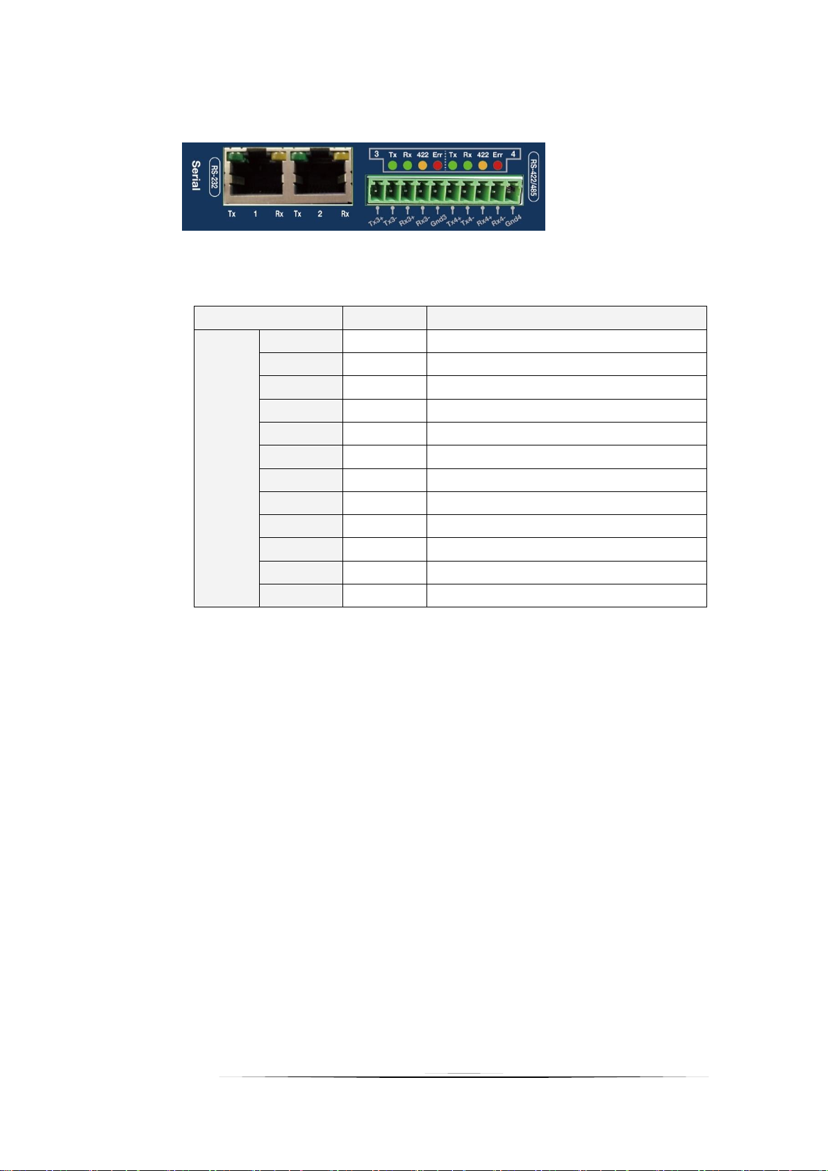
[Front LED of RS-232 2Port + RS-422/RS-485 2Port]
2.6.4.2. SIO RS-232 2Port + RS-422/RS-485 2Port LED
LED Status during Normal Operation
- 22 -
Page 23

Name
LED Color
Operating Status
Serial
TX1
GREEN
Serial CH1 의 TX 시 ON
RX1
GREEN
Serial CH1 의 RX 시 ON
422
YELLOW
ON at RS-422 mode
Err
RED
ON at frame error
TX2
GREEN
ON at TX of Serial CH2
RX2
GREEN
ON at RX of Serial CH2
422
YELLOW
ON at RS-422 mode
Err
RED
ON at frame error
TX3
GREEN
ON at TX of Serial CH3
RX3
GREEN
ON at RX of Serial CH3
422
YELLOW
ON at RS-422 mode
Err
RED
ON at frame error
TX4
GREEN
ON at TX of Serial CH4
RX4
GREEN
ON at RX of Serial CH4
422
YELLOW
ON at RS-422 mode
Err
RED
ON at frame error
[Front LED of RS-422/RS-485 4Port]
2.6.4.3. RS-422/RS-485 4Port LED
LED Status
- 23 -
Page 24

Contents
3.1
Power Supply and Connector(ETOS-100XP/150XP)
3.2
Power Supply and Connector(ETOS-500XP)
3.3
Ethernet connection
3.4
Serial connection
INSTALLATION AND WIRING CHAPTER3
This chapter explains specifications required for installation and wiring of ETOS-XP Series.
- 24 -
Page 25
3. INSTALLATION AND WIRING
This chapter explains specifications of power supply and connector pins required for the
installation and wiring of ETOS-XP Series.
3.1. Power Supply and Connector of ETOS-100XP/150XP
This section describes the specifications of power supply and connector of ETOS-100XP / 150XP.
3.1.1. Specifications of Power Supply
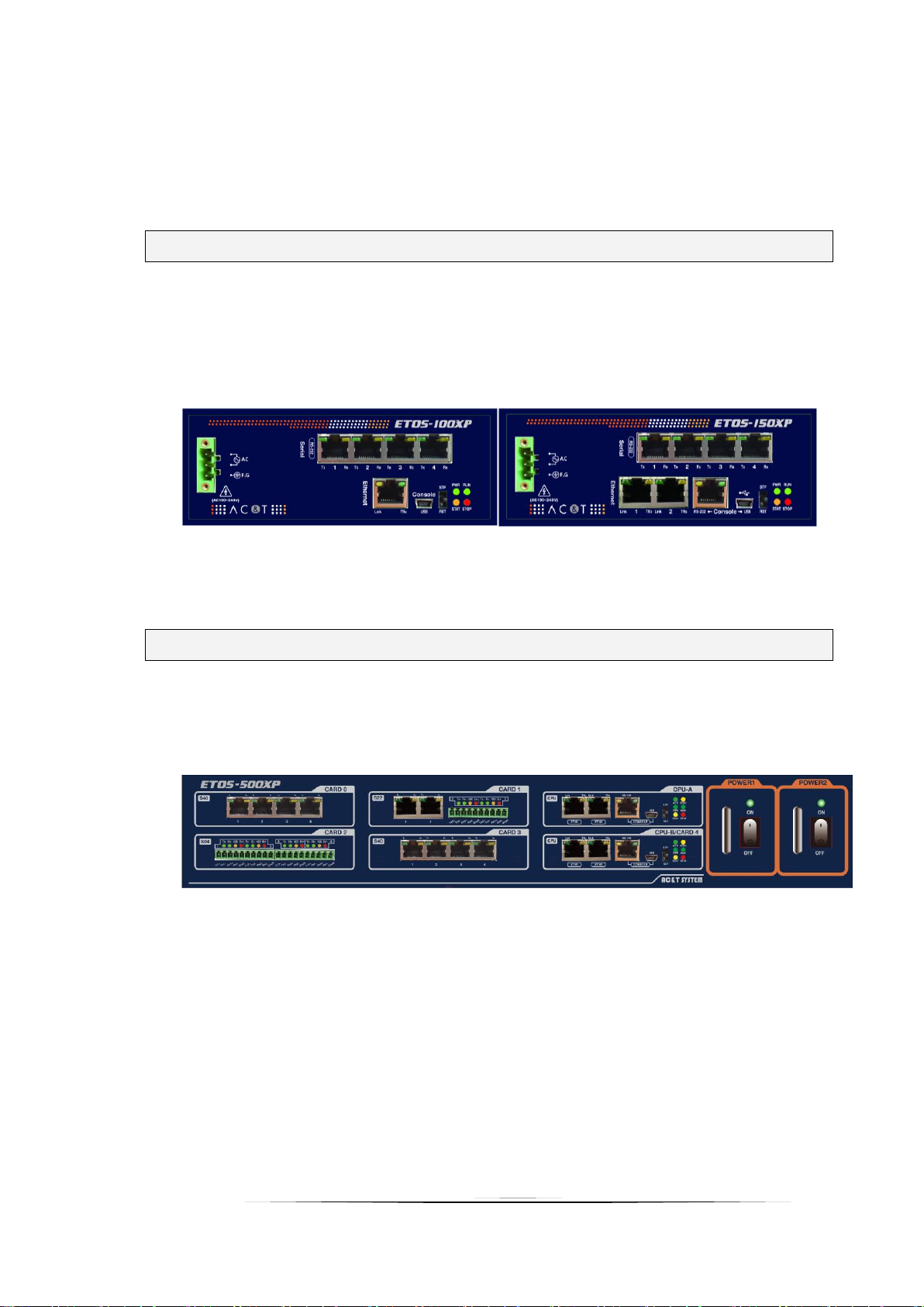
ETOS-100XP / 150XP accepts AC100 ~ 240V power input through the power connector in front of
the product as shown in the following picture.
[ETOS-100XP] [ETOS-150XP]
* Input power supply: AC 100V ~ 240V (Free Voltage), 50/60 Hz
* Power supply must be connected to Frame Ground.
3.2. Power Supply and Connector of ETOS-500XP
3.2.1. Power Supply Specifications
ETOS-500XP accepts AC100 ~ 240V power supply input through the rear power supply connector of
the products in the following picture.
[ETOS-500XP]
* Input power supply:
AC 100V ~ 240V (Free Voltage), 50/60 Hz
90 ~ 130VDC (130W)
* Power supply must be connected to ground (F.G).
- 25 -
Page 26

1 8
Pin
No.
Name
Signal Direction
Function Description
1
TD +
Transmit Ethernet (+)
2
TD -
Transmit Ethernet (-)
3
RD + Receive Ethernet (+)
4
-
N/A
5
-
N/A
6
RD - Receive Ethernet (-)
7
-
N/A
8
-
N/A
[RJ-45 Connector (Plug End)
Pin No.]
[CPU Ethernet port specifications]
3.3. Ethernet Connection
3.3.1. How to Connect the Ethernet Port
The ETOS-XP series offers up to four Ethernet ports. The RJ-45 connector must be used for the
connection and the pin array is as follows.
Connect the ETOS-XP series to the external device as in the following picture.
※ The ETOS-XP series supports both direct and cross connection cables.
- 26 -
Page 27

1 8
Pin
No.
Name
Signal Direction
Function Description
1
CD
DCE notifies DTE of detected carrier
2
RXD
Receive data signals
3
TXD
Transmit data signals
4
DTR
DTE notifies DCE that DTE is ready for
communication
5
SG
-
SG - Ground wire for signaling
6
DSR
DCE notifies DTE that DCE is ready for
communication
7
RTS
DTE requests DCE for data transmission
RJ-45
Connector
8
CTS
DCE notifies DTE that data can be sent
3.4. Serial Connection
ETOS-100XP / 150XP provides up to 4 serial ports, and ETOS-500XP provides up to 20 serial ports.
They are located on the front side of the product as shown below.
3.4.1. RS-232 port Specifications and Wiring
The following table shows each pin name, function, and data direction of the RS-232 serial
port of the ETOS-XP series.
[Serial Port Specification for RS-232 of ETOS-XP Series]
- 27 -
Page 28

3 (TxD)
5 (SG)
2 (RxD)
3 (TxD)
5 (SG)
2 (RxD)
외부통신기기
ETOS (RJ-45)
1
2
3
4
5
6
7
8
9
1
8
[Connection Diagram of RS-232 Null Modem]
Connection diagram of RS-232C
Null modem connection refers to the method that directly connects RS-232 port of ETOS-XP
series to external device. External device and RS-232 port of ETOS-XP series must be connected
as in the following picture.
When hardware handshake is used from an external device, it may be necessary to
forcibly connect the pins of the external device. Refer to the manual of the
external communication device.
- 28 -
Page 29

터미널블럭 커넥터
Pin No.
Name
Signal Direction
Function Description
1
TXD+
RS-422 Transmit Data(+)
2
TXD-
RS-422 Transmit Data(-)
3
RXD+
RS-422 Receive Data(+)
4
RXD-
RS-422 Receive Data(-)
5
SG1
-
Signal Ground1
6
TXD+
RS-422 Transmit Data(+)
7
TXD-
RS-422 Transmit Data(-)
8 RXD+
RS-422 Receive Data(+)
9 RXD-
RS-422 Receive Data(-)
10
SG2
-
Signal Ground2
2 (TXD-)
3 (RXD+)
4 (RXD-)
6 (TXD+)
8 (RXD+)
9 (RXD-)
7 (TXD-)
5 (SG1)
10 (SG2)
(TXD+)
(TXD-)
(RXD+)
(RXD-)
(TXD+)
(TXD-)
(RXD+)
(RXD-)
1 (TXD+)
ETOS-XP
[ RS-422 Connection Diagram ]
3.4.2. RS-422 port Specifications and Wiring
The following table shows each pin name, function, and data direction of the terminal block
(10p) for RS-422/RS-485 serial port of the ETOS-XP.
[Specification of RS-422 port]
The following figure shows the RS-422 connection method between ETOS-XP and external device.
- 29 -
Page 30

Pin No.
Name
Signal Direction
Function Description
1-3, 6-8
TRX+
↔
RS-485 Transmit/Receive Data(+)
2-4, 7-9
TRX-
↔
RS-485 Transmit/Receive Data(-)
2 (TXD-)
3 (RXD+)
4 (RXD-)
6 (TXD+)
8 (RXD+)
9 (RXD-)
7 (TXD-)
5 (SG1)
10 (SG2)
(TXD+)
(TXD-)
(RXD+)
(RXD-)
(TXD+)
(TXD-)
(RXD+)
(RXD-)
1 (TXD+)
ETOS-XP
3.4.3. RS-485 port Specifications and Wiring
The following table shows the pin names, functions, and data direction of the RS-485
communication port.
[RS-485 Port Specification of ETOS-XP Series]
The following figure shows the RS-485 connection method between ETOS-XP and external device.
[ RS-485 Connection Diagram ]
- 30 -
Page 31
Appendix - Dimension
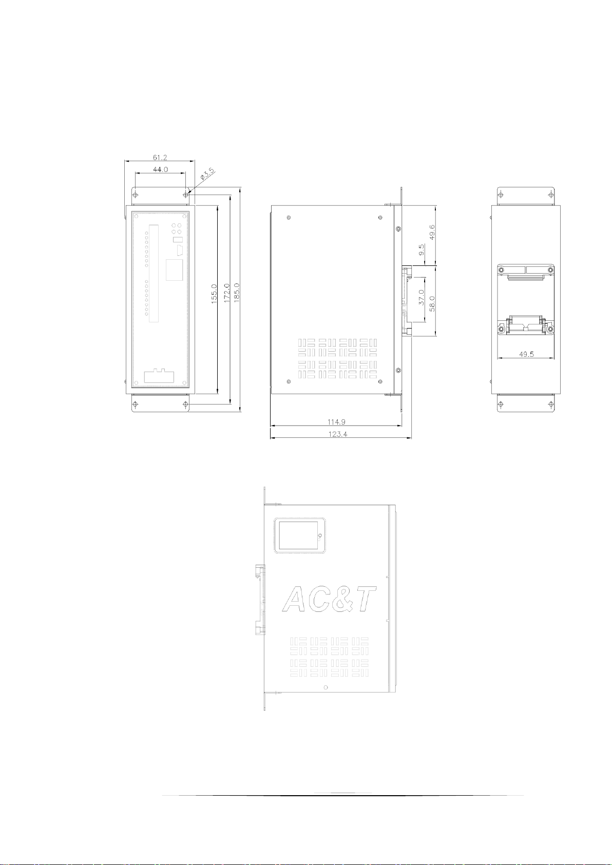
A.1. ETOS-100XP/150XP [Unit: mm]
- 31 -
Page 32

A.2. ETOS-500XP [Unit: mm]
- 32 -
 Loading...