

Page 1
Operating Instructions
CALMASTER
InHouse Multimeter Calibration TestBox
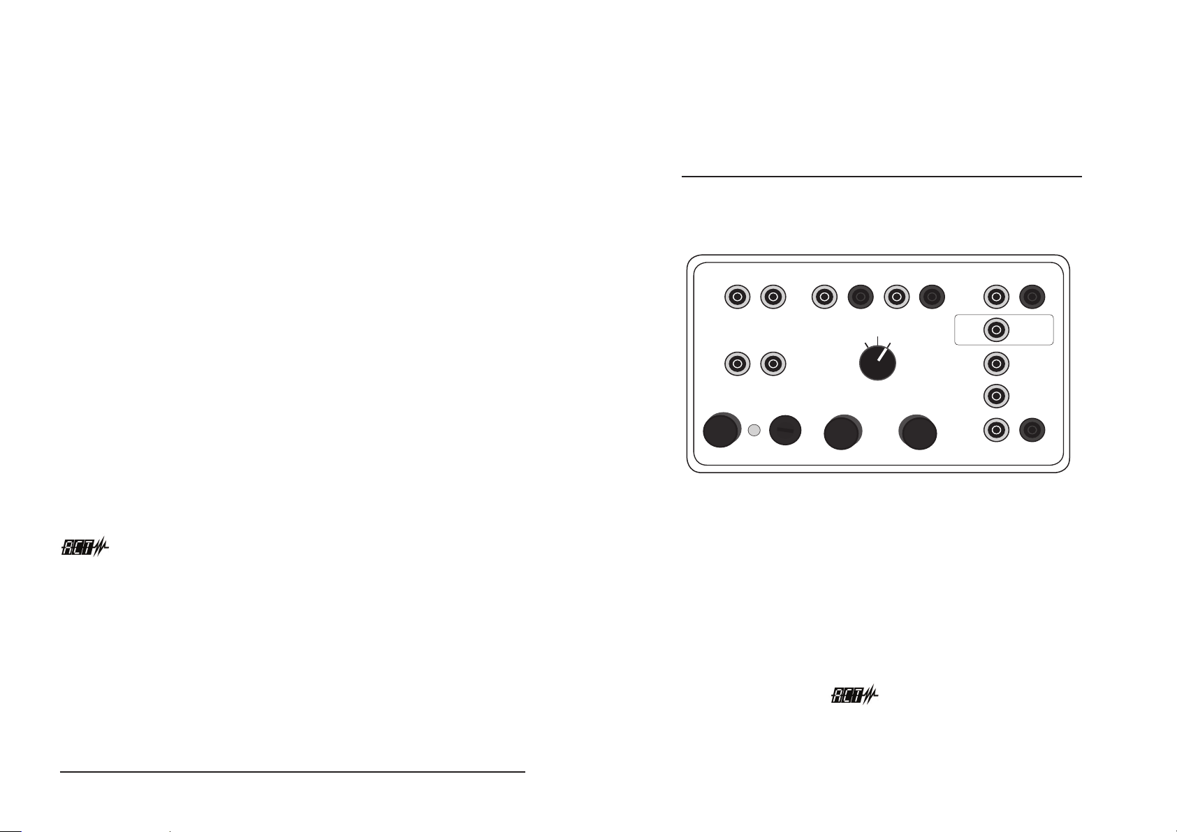
CALIBRATED METER CALIBRATED METER METER UNDER TEST CALIBRATED METER
Ω
METER
UNDER TEST
Ω
METER UNDER TEST
ISOLATED AC OUTPUT
AC VOLT ADJUST FUSE (5OmA MAX)
POWER ON
MIN
CALIBRATED
METER
ACT CALMASTER
RESISTANCE: UP TO 1OOk
DC VOLTS O - 36VDC MAX
MIN MAXMAX
COARSE
DCV BOTH
METERS
MIN
FINE
MAX
1A
1OOmA
1OmA
1mA
SWITCH TO DC
1O/2OA RANGE
METER UNDER TEST
DC CURRENT RANGES
ACT Meters Ltd
The Old Smithy
Church Road
Rainford
Merseyside
WA11 8HD
United Kingdom
w: www.actmeters.com
e: [email protected]
t: +44(0)1744 886660
f: +44(0)1744 886661
Ensure your multimeters are always deemed accurate with
CALMASTER. This useful bench tester checks that meter
ranges are to calibration standard. It’s quick and easy to use
- and reduces the number of meters sent away unnecessarily
for calibration.
Meters Ltd
www.actmeters.com
+44(0)1744 886660
CALINST/0513
Page 2

CALMASTER
CALMASTER
Important Information
CALMASTER works in conjunction with your own calibrated multimeter.
It quickly compares accuracy between the calibrated multimeter and
meter under test. It allows you to test and verify the various ranges for
AC/DC Voltage, Resistance and DC Current. Readings within ±5% of the
calibrated multimeter will prove the meter under test is deemed accurate
to BS ISO9001 standards.
PLEASE NOTE: Input sockets are provided for the calibrated meter and
meter under test. Controls are provided to adjust AC/DC voltages and
a switch to select functions. CALMASTER is powered from a switchable
115VAC or 230VAC supply. A RED neon indicates when AC power is on.
WARNING: DAMAGE OR INJURY MAY RESULT IF 115VAC IS SELECTED
AND CONNECTED TO A 230VAC SUPPLY. Safety fuses are provided for
input and output AC supplies
Notes
2
www.actmeters.com
www.actmeters.com
7
Page 3

CALMASTER
CALMASTER
Operating Instructions
FIRST STEPS
1. Connect power lead between CALMASTER and suitable AC mains
supply
2. Switch on AC supply and conrm that CALMASTER red neon is lit
3. Turn all CALMASTER controls to the fully anti-clockwise position
4. IMPORTANT: Remove AC mains lead when testing resistance to
ensure stable resistance reading
Testing AC Voltage
1. Connect ‘Calibrated Meter’ and ‘Meter Under Test’ to CALMASTER left
sockets
2. Switch both ranges to ‘AC Volts’ range
3. Turn ‘AC Volt Adjust’ to the desired voltage and conrm that the
‘Meter Under Test’ reading is within ±5% of the reading displayed on
the ‘Calibrated Meter’
4. Log readings obtained for calibration records
5. Repeat above on all AC voltage ranges on the meters
6. On completion return all control back to the fully anti-clockwise
position
Operating Instructions
Testing Resistance
1. Connect ‘Calibrated Meter’ and ‘Meter Under Test’ to the CALMASTER
middle sockets
2. Switch both meters to ‘Resistance’ range
3. Turn the ‘FINE’ or ‘COARSE’ controls to the desired resistance on the
‘Calibrated Meter’
4. Switch the CALMASTER from the ‘Calibrated Meter’ to the ‘Meter
Under Test’ and conrm that the reading is within ±5% of the reading
on the ‘Calibrated Meter’
5. Log readings obtained for calibration records
6. Repeat above on all resistance ranges on the meters
7. On completion return all controls back to the fully anti-clockwise
position
Testing DC Voltage
8. Connect ‘Calibrated Meter’ and ‘Meter Under Test’ to the CALMASTER
middle sockets
9. Switch both meters to ‘DC Volts’ range
10. Switch CALMASTER to the ‘DCV Both Meters’ position
11. Turn the ‘FINE’ or ‘COARSE’ controls to the desired voltage and
conrm that the ‘Meter Under Test’ voltage reading is within ±5% of
the reading displayed on the ‘Calibrated Meter’
12. Log readings obtained for calibration records
13. Repeat above on all DC voltage ranges on the meters
14. On completion return all controls back to the fully anti-clockwise
position
4
www.actmeters.com
www.actmeters.com
5
Page 4
CALMASTER
CALMASTER
Operating Instructions
Testing DC Current
1. Connect ‘Calibrated Meter’ and ‘Meter Under Test’ to the CALMASTER
right sockets
2. Switch both meter to ‘DC mA’ range
3. Conrm that the ‘Meter Under Test’ mA reading is within ±5% of the
reading displayed on the ‘Calibrated Meter’
4. Log readings obtained for calibration records
5. Repeat above on all DC current ranges on the meters
WARNING: ON 10AMP RANGE MAX TEST TIME 30 SECONDS
Specications
Resistance AC Volts DC Volts DC Current
00.0Ω up to 100K 0.0 to 230VAC 0.0 to 36VDC 1mA
10mA
100mA
1Amp
Operating Instructions
Contents
First Steps ..................................................................................................... 4
Testing AC Voltage ....................................................................................... 4
Testing Resistance ....................................................................................... 5
Testing DC Voltage ..................................................................................... 5
Testing DC Current ...................................................................................... 6
Specications ............................................................................................... 6
Fuse Protection (AC Input) 250VAC, 1.6Amp max
(AC Output) 250VAC, 50mA max
Weight 2.2KG
Dimensions 216(L) x 132(W) x 102(D)mm
6
www.actmeters.com
3
www.actmeters.com
 Loading...