

Page 1
Active Thermal Management
The trusted name in thermal protection
SEC-1 Installation Instructions
IMPORTANT – Read completely BEFORE beginning!
While not difficult or complicated, installation of the Small Enclosure
Cooler (SEC-1) does include steps which require basic woodworking
skills and tools. Please read the entire installation procedure and
determine that you are comfortable performing the tasks outlined
before proceeding.
Tools required:
Tape measure
Sabre saw
Philips screwdriver
Pencil and/or marking pen
Electric drill
Drill bit(s) slightly larger than sabre saw blade
The SEC-1 includes a fan panel,
Figure 1
power supply,
Figure 2
SEC-1 Installation instructions Page 1 of 8
97-401-01
Page 2
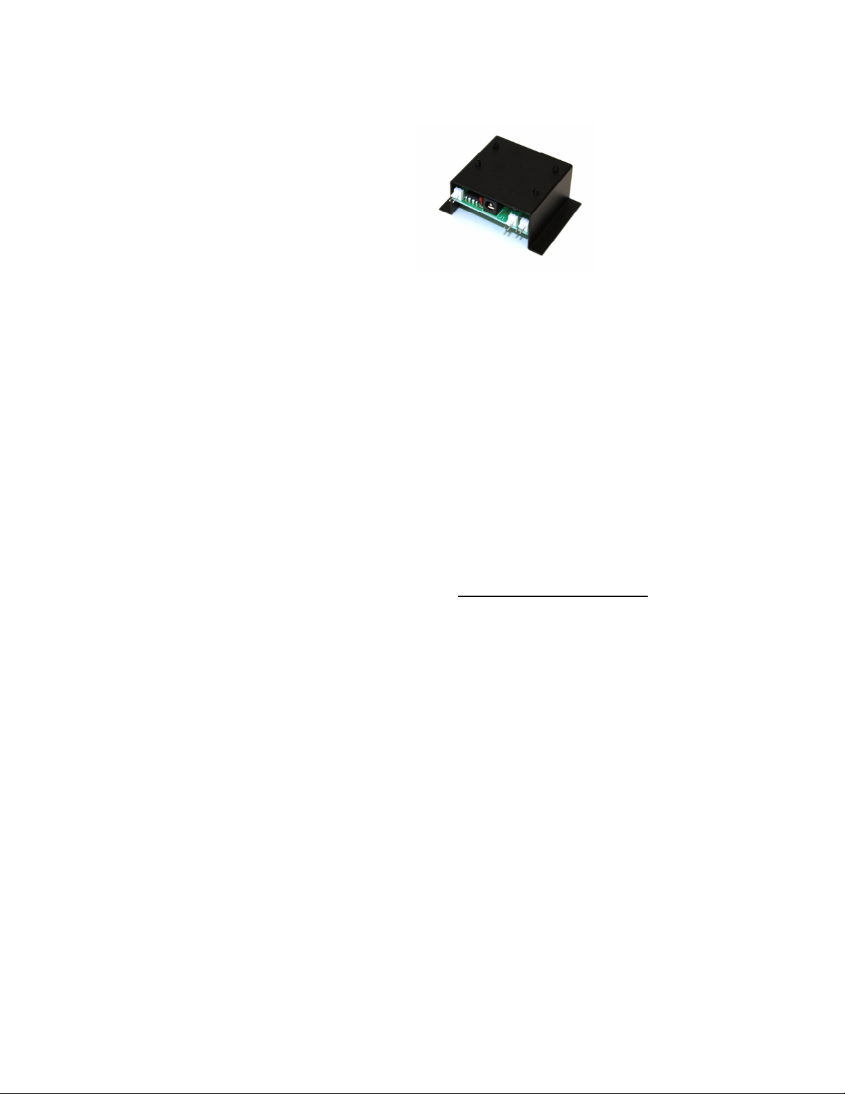
thermal control assembly,
Figure 3
screws for fastening the fan panel to a cabinet
panel, wire ties, and wire tie anchors. It is designed for installation in an
enclosure or cabinet up to about
12 cubic feet in volume, typically measuring (approximately) 2’ x 3’ x 2’
with no more than 1 shelf, or a small section of a larger enclosure. It can
cool several pieces of audio-video equipment, usually a cable box (or
satellite receiver), multi-channel amplifier, and 1 or 2 other items which do
not generate significant heat. It is NOT intended to cool large enclosures
holding many pieces of equipment or more than one device known to run
extremely hot.
Active Thermal Management offers cooling equipment for more elaborate
installations through its network of professional installers in the US and
Canada; more information is available at www.activethermal.com.
A quick overview:
1. Mount the fan panel.
2. Provide an opening for fresh air to enter the cabinet.
DO NOT BEGIN INSTALLATION UNTIL THE LOCATIONS
OF THE FAN PANEL AND THE FRESH AIR OPENING ARE
DETERMINED!
3. Place the thermal control unit on or near the device whose
temperature is to be monitored. Place the thermal probe on the
equipment to be monitored.
SEC-1 Installation instructions Page 2 of 8
97-401-01
Page 3
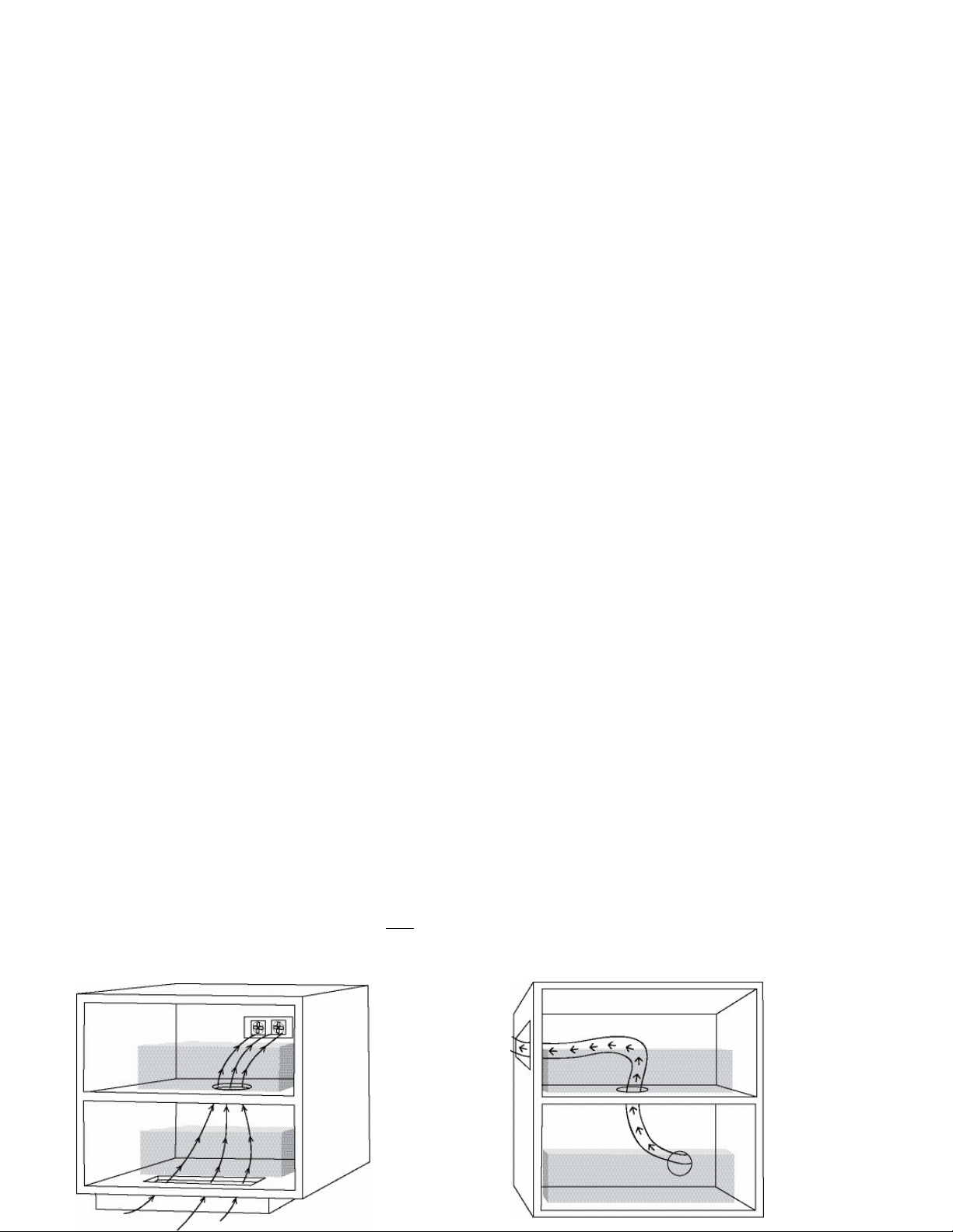
4. Plug the fan, thermal probe, and power supply plugs into the mating
connectors on the thermal control unit.
When the temperature of the thermal probe reaches 88 – 90 degrees, the fans
will switch on and a red LED will light. A green LED on the thermal
control assembly is lighted at all times, indicating that the SEC-1 is
receiving power.
Given the wide range of cabinetry and equipment combinations available,
and variations in mounting locations possible, Active Thermal Management
cannot guarantee that a given installation will be completely effective at
maintaining safe temperatures. The air path may be too restricted or not
directed properly, the equipment within the enclosure may generate heat
beyond its capacity, or the enclosure may be too large.
IT IS THE REPONSIBILITY OF THE OWNER AND/OR
INSTALLER TO DETERMINE THAT THE VENTILATION
PROVIDED IS ADEQUATE; UNDER NO CIRCUMSTANCES
SHALL ACTIVE THERMAL MANAGEMENT BE LIABLE TO THE
ORIGINAL PURCHASER OR ANY OTHER PERSON FOR ANY
INCIDENTAL, SPECIAL, OR CONSEQUENTIAL DAMAGES,
WHETHER ARISING OUT OF BREACH OF WARRANTY,
BREACH OF CONTRACT OR OTHERWISE.
Detailed installation instructions:
1. Determine the location for the fan panel. The fans are supplied
with 38” long wires, allowing great flexibility in mounting.
Ideally, the fan panel should be mounted as high as possible, and
toward the rear of the enclosure. (Note: Normally, the labels on
the fans will face out of the enclosure.)
SEC-1 Installation instructions Page 3 of 8
97-401-01
Page 4
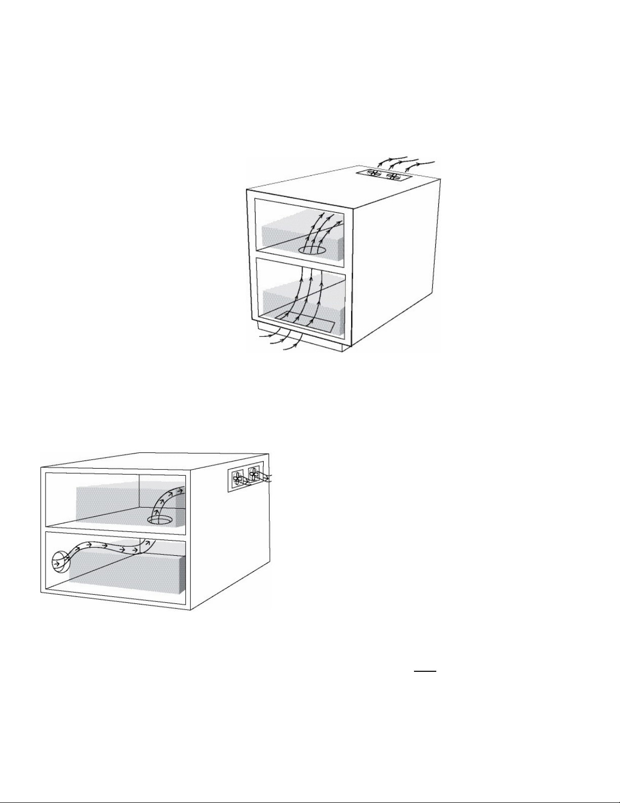
Fig.4
F
ig.5
Fig. 6
The drawings show several
possible locations for mounting the
fan panel and a fresh air intake.
The best location for your
installation depends on several
factors:
• Is there a
minimum of
2” of
clearance between the back of the enclosure and the wall,
allowing rear panel mounting? See figures 4 & 5.
• If not, is mounting the fan panel on the side(s) or top of the
enclosure possible? See figures 5, 6 and 7.
Fig. 7
• If not, and the cabinet stands
on feet (air can circulate freely
under the cabinet), is
mounting the fan panel on the
cabinet floor possible? In this case, the panel would be oriented
so that air would be taken in from below, and blown up into the
cabinet. (The labels on the fans would face into the enclosure
in such an installation.) An opening for heated air to escape
through would have to be provided high in the cabinet.
SEC-1 Installation instructions Page 4 of 8
97-401-01
Page 5
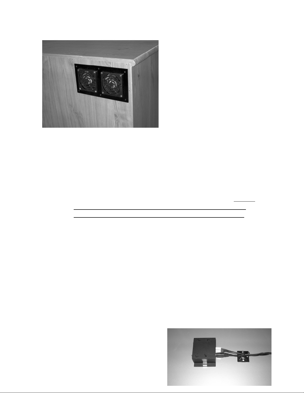
After determining the location for
the fan panel, cut a 3 ½” x 7 ½ ”
rectangular opening. With the fan
wires inside the cabinet, mount
the fan panel from the outside of
Fig. 8
the cabinet as illustrated in figure 8, using the six ½” long Philips-head
screws supplied; you may wish to drill pilot holes before installing the
screws. If they are not appropriate for your cabinet, procure the right
fasteners at a home improvement or hardware store.
2. Provision must be made to allow room air to enter the enclosure to
replace the hot air being expelled by the SEC-1. A location low in
the enclosure and toward the front is generally preferred; the best
arrangement is that in which air enters and passes by the heatgenerating equipment on its way to the SEC-1's exhaust fans.
Ideally, the fans and fresh air inlet(s) would be located so that a line
drawn between them would pass through the equipment to be cooled.
An Important Note
The intake opening should be no less than 10 square inches. A slot 2” x 5”,
1” x 10”, or two 3” round holes should be adequate. Note the suggested
fresh air inlet locations in the drawings.
An air inlet(s) improperly located or too small will prevent the SEC-1 from
operating efficiently.
• Avoid locating the inlet too close to
the fan panel; room air may enter and
SEC-1 Installation instructions Page 5 of 8
97-401-01
Page 6
be immediately exhausted without cooling the
equipment. .
Fig. 9
• Generous holes (two 3” diameter or one 4” diameter) must be made in
any shelf in the air path to allow air to pass through. Center the holes
under the equipment, so that air flows up and around the equipment on
the shelf.
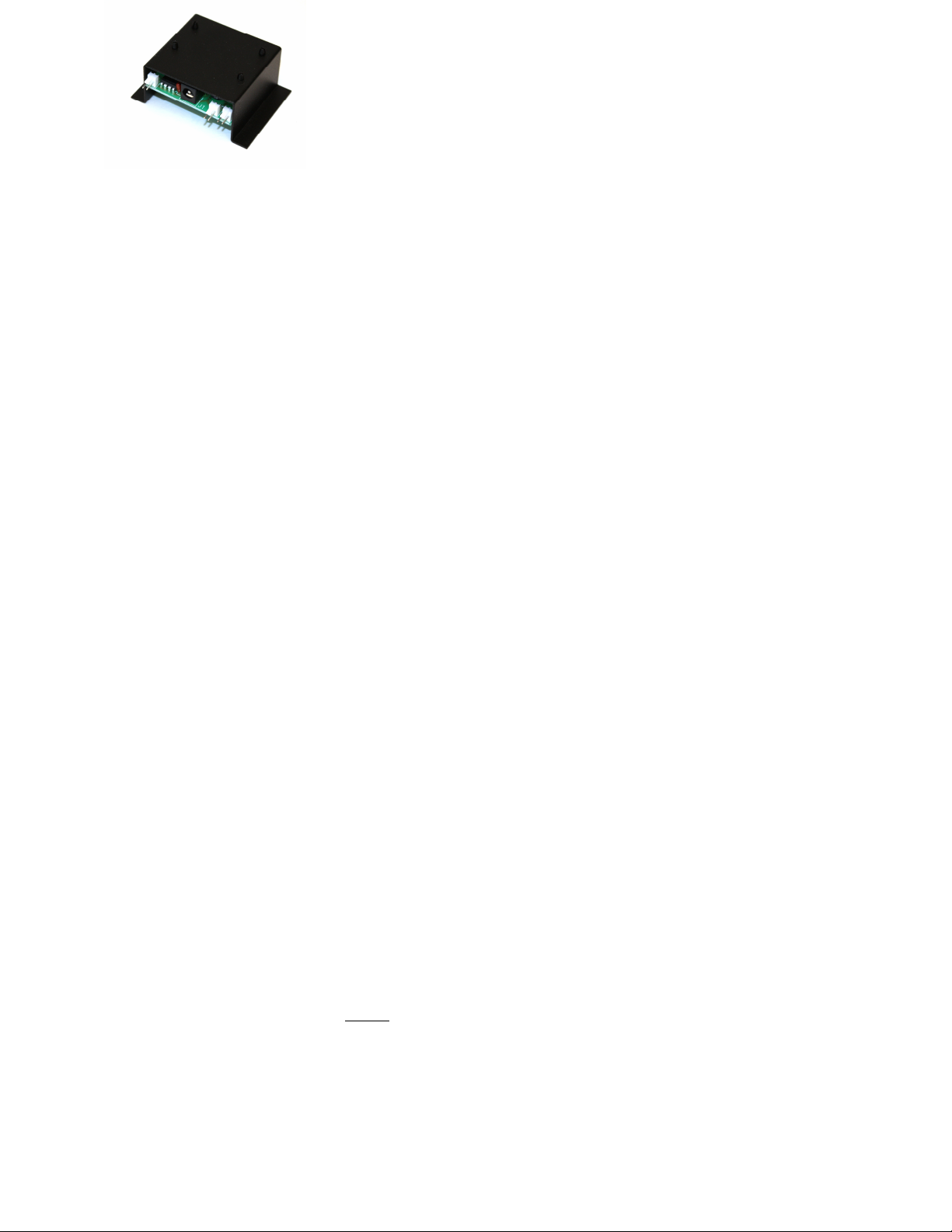
3. Place the thermal probe on the equipment to be monitored. Small
magnets on the side flanges of the control unit’s metal cover will
hold it firmly in place on equipment with steel covers. Some
equipment may use aluminum covers; in this case, use the wire
ties and wire tie anchors near the thermal switch assembly to keep
the unit in place, as shown in Figure 9.
4. Plug the power supply into the mating jack J1 on the control unit,
and plug the fans into the 2-pin connectors FAN1 and FAN2, as
shown in Figure 10. Note that the fan plugs can only be inserted
one way. Plug the thermal probe into the THRM connector.
The SEC-1 is powered by a wall-type power supply. Do not plug it into a
switched outlet; use an AC outlet which is always live. If possible, use an
outlet on the
Fig. 10
same circuit that powers the equipment producing the most heat. If this
circuit breaker should trip, the ventilation will stop, but the heat source will
also turn off. If the SEC-1 is powered from a different circuit, it is possible
that the fans could lose power while the equipment in the enclosure
continued to produce heat.
In case of difficulty:
If the equipment enclosure is still hot:
• And the fans are NOT turning –
SEC-1 Installation instructions Page 6 of 8
97-401-01
Page 7

The SEC-1 may not be receiving power; is the green led
lighted?
Is the power supply plugged into an always-live AC
outlet?
Is the power supply plugged into the control unit?
Are the fans plugged into the thermal switch assembly?
Is the thermal probe plugged into the control unit and on
or just above a hot piece of equipment?
• And the fans ARE turning –
Have you provided an adequately-sized and properly positioned fresh
air opening?
W
ARRANTY
Active Thermal Management (“ATM”) warrants its products against defects in materials
and workmanship for a period of one year from date of purchase. We will repair or
replace, at our option, any ATM product which has a defect in materials or workmanship.
The product must be properly packaged and returned prepaid with an ATM return
authorization number clearly written on the outside of the shipping carton and with a
copy of the bill of sale or ATM invoice to verify the original purchase date.
Our warranty does NOT apply to:
1. Shipping damage, either concealed or visible. Claims must be filed with the carrier.
2. Damage caused by improper installation or improper electrical voltage.
3. Any product which has been modified, unless authorized by ATM.
4. Damage caused by corrosion, abrasion, immersion, or severe temperatures.
5. Products which have been subject to abuse, misuse, abnormal usage, or accident.
These warranties give you specific legal rights, and are subject to any applicable
consumer protection legislation. You may also have additional rights which vary from
state to state.
No other warranties, expressed, implied, or written, shall apply to this product. ATM will
not be responsible for any consequential or incidental damages, loss of property,
revenues, or profit, cost of removal, installation, or reinstallation, personal injury, or for
any breach of warranty, regardless of how caused.
SEC-1 Installation instructions Page 7 of 8
97-401-01
Page 8

SEC-1 Installation instructions Page 8 of 8
97-401-01
 Loading...