

Page 1

Solutions for the Digital Life
™
User Manual
54 Mbps
Wireless
DSL Gateway
Model #: GT701-WG
Page 2

Table of Contents
1 Introduction 1
Package Contents 1
Minimum System Requirements 1
Features 2
Technical Support 5
2 Setting Up the Gateway 9
Attention! 9
Connecting a Computer to the Gateway 10
Installing Phone Filters 27
Setting Up the DSL Connection 34
3 Using Qwest DSL 41
Connecting to the Internet 41
Disconnecting from the Internet 41
4 Basic Setup 43
Basic Setup 43
5 Setting Up Static IP Address 47
Configuring for a Single Static IP Address 47
Configuring for a Block of Static IP Addresses 51
6 Advanced Setup 57
Accessing Advanced Setup 57
WAN IP Address 58
Wireless Settings 63
Wireless MAC Authentication 67
LAN IP Address 68
DHCP Server 68
Services Blocking 70
Website Blocking 71
Remote Management 72
Port Forwarding 73
DMZ Hosting 74
Firewall 75
Dynamic Routing 75
NAT (Network Address Translation) 76
Static Routing 76
Status 77
7 Using Utilities 81
Web Activity Log 81
DSL Settings 82
Restore Default Settings 83
Upgrade Firmware 83
i
Page 3

Actiontec 54 Mbps Wireless DSL Gateway User Manual
8 Setting Up a Network 85
Ethernet 85
USB 91
9 Troubleshooting 97
A Reference 101
Locating Computer Information 101
Locating Windows Operating System Files 102
B Static IP Address on the Computer 105
Windows 98 SE 105
Windows Me 108
Windows 2000 111
Windows XP 115
C Computer Security 121
Comparing DSL Service with a Dial-Up Modem 121
Gateway Security 122
Computer Security 122
Electronic Security 123
D Specifications 125
General 125
Wireless Operating Range 126
LED Indicators 126
Environmental 126
E Glossary 127
F Firewall Security Level Services Table 131
High Security Level 131
Medium Security Level 132
Low Security Level 132
Basic Security Level 132
Service Acronym Definitions 133
G Non-Windows System Setup 135
Classic 135
OS X 137
Connecting to the ISP 138
Notices 141
Regulatory Compliance Notices 141
Modifications 141
Limited Warranty 143
ii
ii
Page 4
Introduction
1
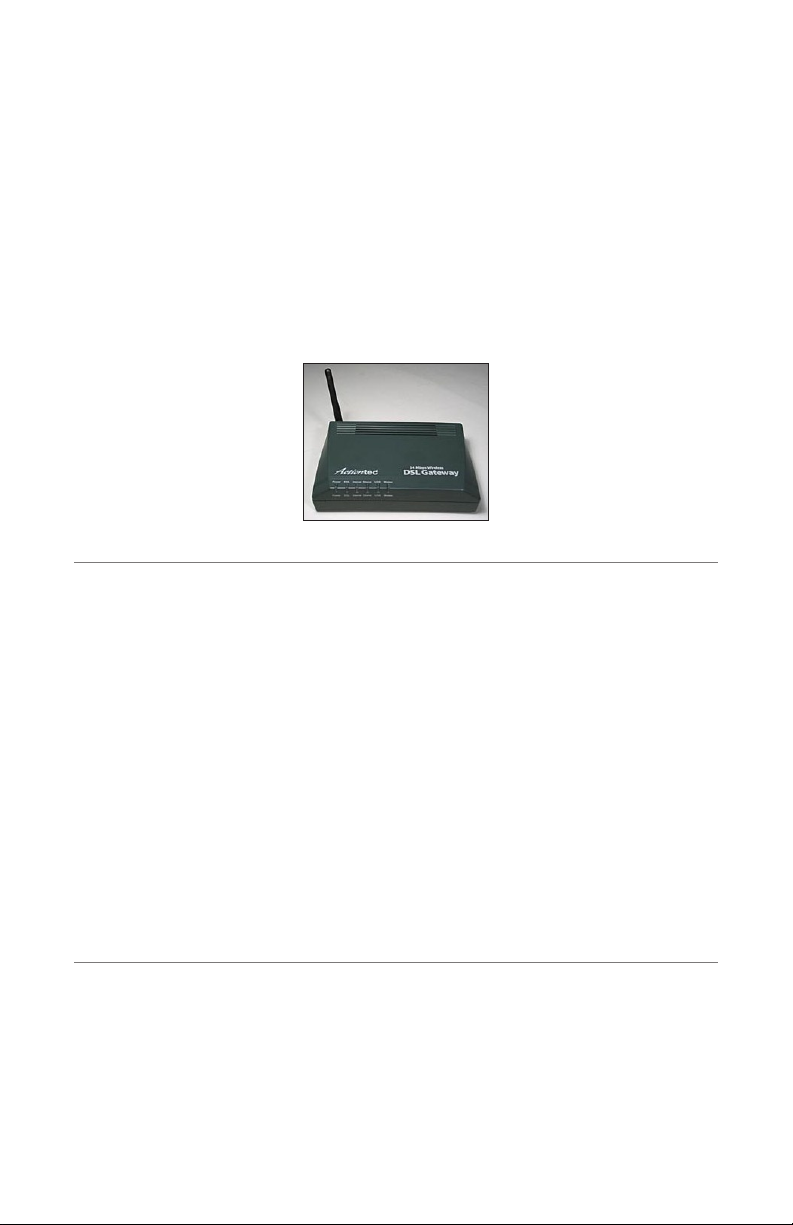
Thank you for purchasing the Actiontec 54 Mbps Wireless Gateway. The Gateway
is the simplest way to connect computers to a high-speed broadband connection.
This easy-to-use product is perfect for the office or small business. If you want to
take your computing to the next level, the Actiontec 54 Mbps Wireless Gateway is
sure to be one of the keys to your success.
Package Contents
s Actiontec 54 Mbps Wireless Gateway
s Power adapter
s Phone filters
s DSL cable
s Ethernet cable
s USB cable
s Installation CD-ROM
s Quick start guides
Minimum System Requirements
s Active DSL service
s Computer with an 10 Mbps or 10/100 Mbps Ethernet connection, or USB
connection
1
Page 5
Actiontec 54 Mbps Wireless DSL Gateway User Manual
3
Chapter 1 Introduction
Power
DSL
Interne
t
E
thernet
US
B
Wire
less
Power
DSL
Intern
et
E
ther
n
et
US
B
Wireless
s Microsoft Windows 98 Second Edition (SE), Windows Millennium Edition
(Me), Windows NT 4.0, Windows 2000, Windows XP, Mac OS 7.1+, Mac OS
8.0+, Mac OS 9.0+, or Mac OS X+
Note: USB LAN port is not supported with Microsoft Windows
☞
95, Windows NT 4.0, and Mac OS.
s Internet Explorer 5.0 or higher (6.x recommended) or Netscape Navigator
4.0 or higher (4.7 recommended)
s TCP/IP network protocol installed on each computer
Features
This section contains a quick description of the Gateway’s lights, ports, etc.
The Gateway has several indicator lights (LEDs) on its front panel and a series of
ports on its rear panel.
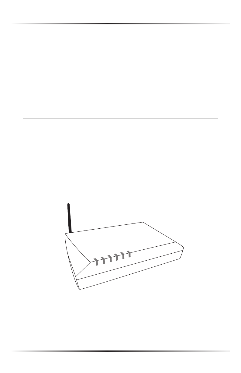
Front Panel
The front panel of the Gateway features six lights: Power, DSL, Internet, Ethernet,
USB, and Wireless.
2
Page 6

Chapter 1 Introduction
Power Light
The Power Light displays the Gateway’s current status. If the Power Light glows
steadily green, the Gateway is receiving power and fully operational. When the
Power Light is rapidly flashing, the Gateway is initializing. If the Power Light is
not illuminated when the power cord is plugged in, the Gateway has suffered a
critical error and technical support should be contacted.
DSL Light
The DSL light illuminates when the Gateway is connected to a DSL line.
Internet Light
When the Internet Light glows steadily, the Gateway is connected to the DSL
provider. When it flashes, the Gateway’s built-in DSL modem is training for your
DSL service.
Ethernet Light
The Ethernet light illuminates when the Gateway is connected via its Ethernet
Port.
USB Light
The USB light illuminates when the Gateway is connected via its USB port.
Wireless Light
The Wireless light illuminates when the Gateway is connected wirelessly
3
Page 7
Actiontec 54 Mbps Wireless DSL Gateway User Manual
5
Chapter 1 Introduction
Power
USB
Ethe
r
n
e
t
Li
n
e
Re
s
et
P
h
o
n
e
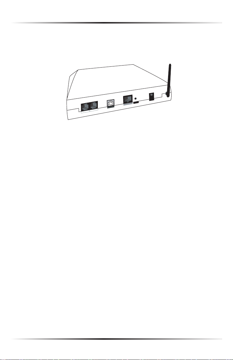
Rear Panel
The rear panel of the Gateway contains eight ports (Ethernet [4], Line, Phone,
USB, and Power), as well as a Reset switch.
Line Port
Used to connect the Gateway to a DSL (Digital Subscriber Line) connection.
Phone Port
Used to connect a telephone to the Gateway.
USB Port
Used to connect a computer to the Gateway via USB cable.
Ethernet Port
Used to connect computers to the Gateway via Ethernet cable. The Ethernet port
is a 10/100 Mbps auto-sensing ports, and either a straight-through or crossover
Ethernet cable can be used when connecting to the port.
Reset Switch
Depressing the reset switch for one or two seconds will power cycle (similar to
unplugging and then plugging in the Gateway’s power cord) the Gateway. To
restore the Gateway’s factory default settings, depress and hold the Reset Switch
for approximately 10 seconds. The reset process will start about 10 seconds after
releasing the Reset Switch.
4
Page 8

Chapter 1 Introduction
Power Port
Used to connect the Power Cord to the Gateway.
Warning: Do not unplug the power cord from the Gateway
N
during the reset process. Doing so may result in permanent
damage to the Gateway.
Technical Support
Self Help
To obtain answers to DSL configuration questions, visit the Qwest DSL Actiontec
support page at this address:
http://www.qwest.com/dsl/customerservice/Actiontecgt701-wg.html
A help page is also available on the main page of the Actiontec DSL Gateway Web
interface. Enter
192.168.0.1
in the browser’s address text box, and when the first screen appears, click HELP.
Basic Setup Support
If unable to access the Internet, look at the Internet light on the front of the
DSL Gateway. If the light is solid green, call the ISP immediately. If it is not solid
green, call Qwest at 1-800-247-7285.
Other Problems
Contact the ISP if experiencing problems with:
s DHCP addressing configuration
s Static IP addressing configuration
s Transparent bridging configuration
Contact Qwest at 1-800-247-7285 for:
s DSL service outage support and repair
5
Page 9

Actiontec 54 Mbps Wireless DSL Gateway User Manual
7
Chapter 1 Introduction
s DSL service installation support
Note: Before attempting any of the above, make sure access to
☞
the Internet is available.
Advanced Feature Support
Qwest DSL technical support provides the following advanced feature support for the
Actiontec DSL Gateway. Contact Qwest at 1-800-247-7285 for configuration assistance.
s Enabling Website Blocking
s Enabling VPN Pass-Through
s Enabling/Disabling NAT
s Firewall configuration
s Changing the LAN IP address of the DSL Gateway
s Enabling Services Blocking
s Enabling/Disabling DHCP
s VIP feature
These features are supported in the Gateway only. Implementation of the above
features within the network (LAN) is not supported.
Wired/Wireless Upgrade
Wired and wireless upgrade installation support is available from Actiontec
free of charge if the wired/wireless equipment was purchased from Actiontec.
Contact Actiontec at 1-888-436-0675 for installation and configuration support
information.
Networking (LAN) Support
If a wired/wireless network has been set up and support is needed in one of the
following areas:
s LAN support of multiple computers and peripherals;
s Microsoft Windows Networking;
6
Page 10

Chapter 1 Introduction
s Microsoft Internet Connection Sharing (ICS);
s Advanced LAN configuration with multiple computers;
s Non-Actiontec-provided network card/Ethernet cable installation, configu-
ration, or troubleshooting;
s Commercial firewall software configuration;
contact the Actiontec Pay For Support Center at 1-888-825-9025. Actiontec net-
working support is provided for a fee of $29.95 per incident. Other fee-based fea-
ture support includes:
s Port Forwarding (Static NAT)
s Static Routing
s MAC Address Cloning
s Third-party vendor wireless equipment configuration
s DMZ Hosting
s NAT Routes
s RIP (Dynamic Routing)
This support service does not include an on-site field technician.
To purchase Actiontec wireless cards and peripherals, visit the Actiontec Web site at
www.actiontecstore.com/qwest
7
Page 11

Actiontec 54 Mbps Wireless DSL Gateway User Manual
This page left intentionally blank.
8
Page 12

Setting Up the Gateway
The instructions that follow parallel the steps contained in the Actiontec Installation
Buddy™, which provides a visual guide to setting up the Gateway. It is recommended
the user run the Installation Buddy first, before attempting any other procedures.
To set up the Gateway, it must be connected to a computer, and then configured.
After connecting this first computer, other computers can be added to the network
via USB, Ethernet, or wirelessly (see “Setting Up a Network” on page 63).
Attention!
Read the following two sections (Alarm System, Automatic Water Heater)
before proceeding with any installation!
Alarm System
If your home or business has an alarm system, and if Qwest DSL shares the same
phone line, you have special wiring needs. If you did not order a technician install
at the time of sale, please contact your Security Alarm Provider or Qwest Sales as
soon as possible to order and schedule your installation.
If your security alarm system is wired incorrectly, it may not be able to make a
notification call when the alarm is triggered.
Professional wiring is required to ensure inter-operability. Do not attempt the
installation yourself!
Qwest strongly recommends contacting your security organization for more
information about your security alarm system before attempting to install Qwest
DSL. Qwest also strongly recommends contacting your security organization after
installing Qwest DSL to have them conduct a test of your alarm system.
2
Automatic Water Meter
Although most water companies do not utilize automatic water meters, some do. If
you have an automatic water meter using the same phone line as your Qwest DSL
service, you must install a DSL Phone Filter.
Contact your water company for help installing the DSL Phone Filter on your water
meter, or if you are unsure whether your water meter uses your phone line.
9
Page 13
Actiontec 54 Mbps Wireless DSL Gateway User Manual
11
Chapter 2 Setting Up the Gateway
Connecting a Computer to the Gateway
Connecting a computer to the Gateway for setup involves three basic steps: initial
setup, plugging in the Gateway’s power cord, and connecting the Gateway to the
computer.
Note: The following procedures are for U.S. installations only.
☞
Connecting Via Ethernet
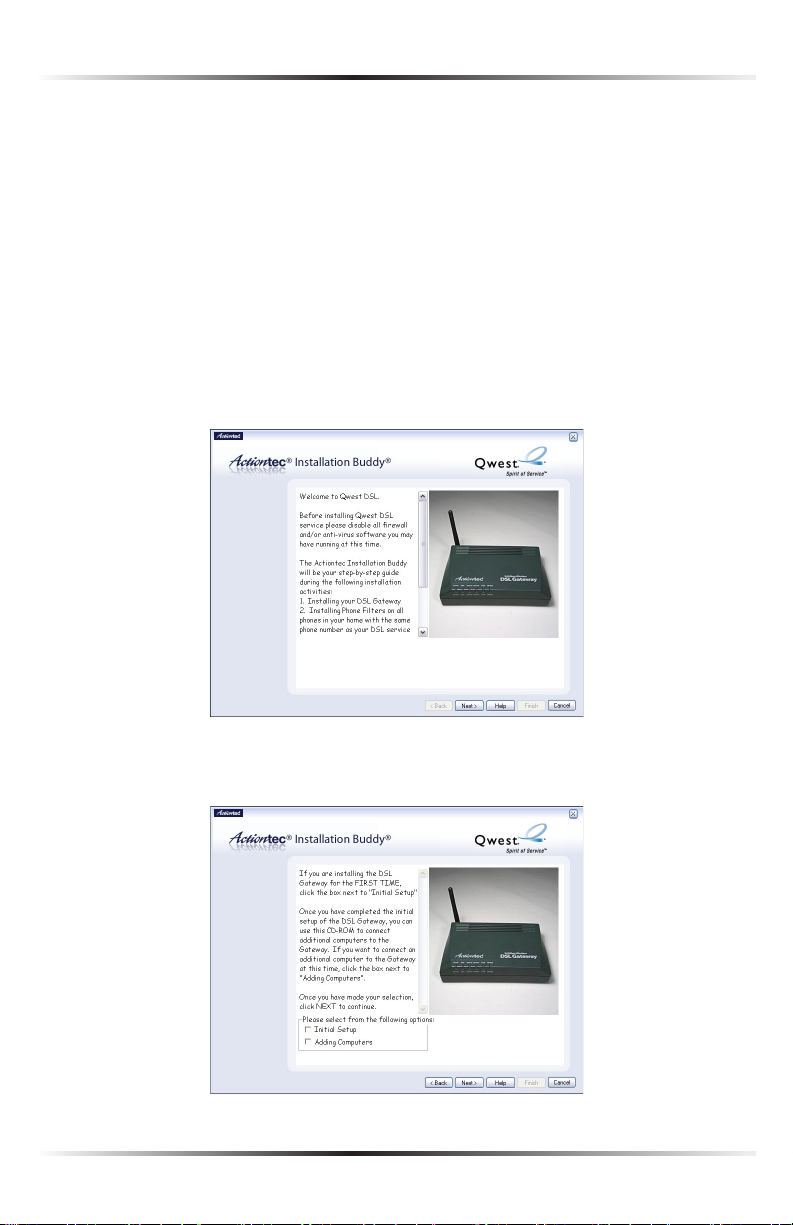
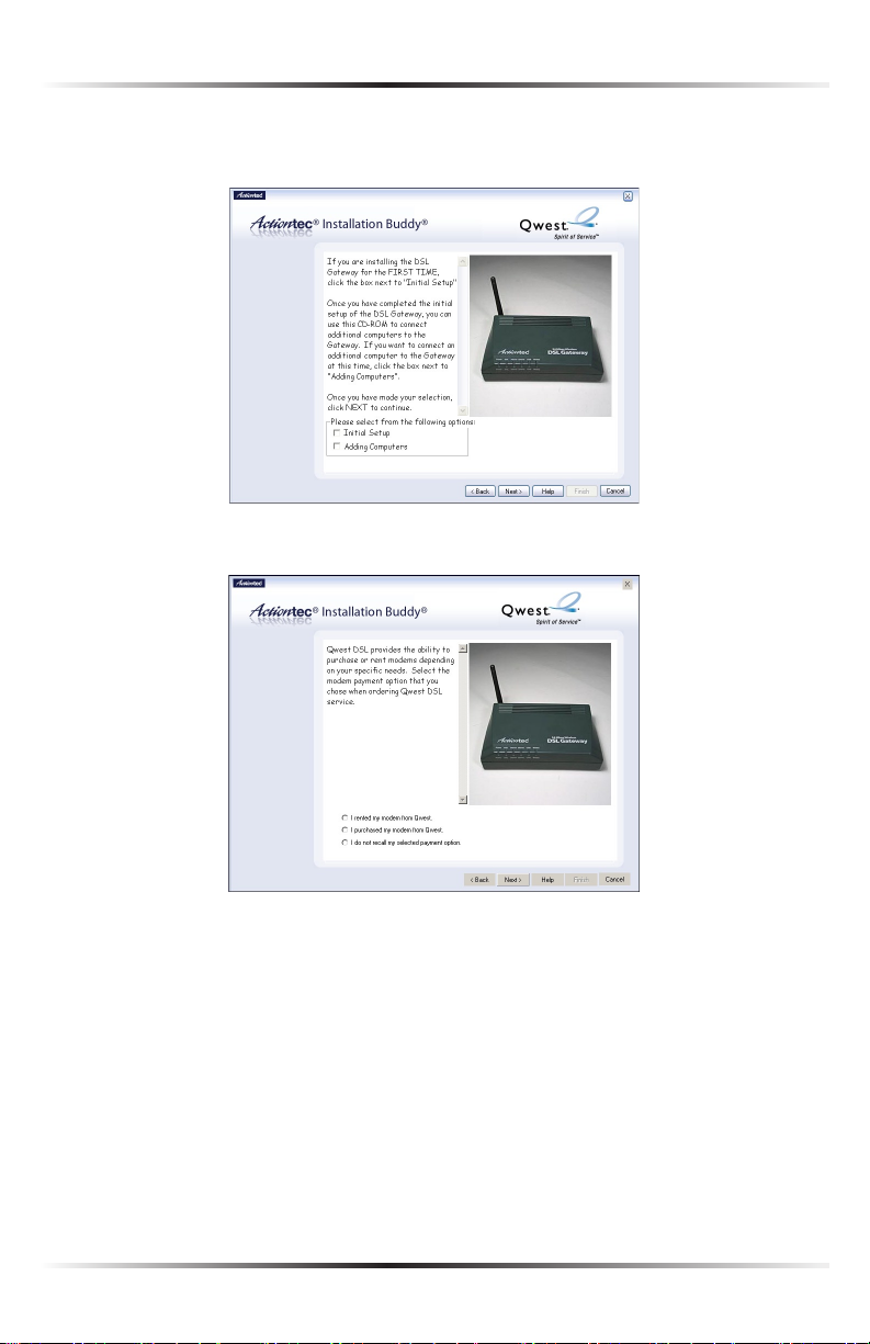
1. Insert the Installation CD in the CD-ROM drive of the computer. The
Installation Buddy will start automatically. Wait until the following screen
appears, read the on-screen instructions, then click Next.
2. Read the instructions, select Initial Setup by clicking on the appropriate check
box, then click Next.
10
Page 14
Chapter 2 Setting Up the Gateway
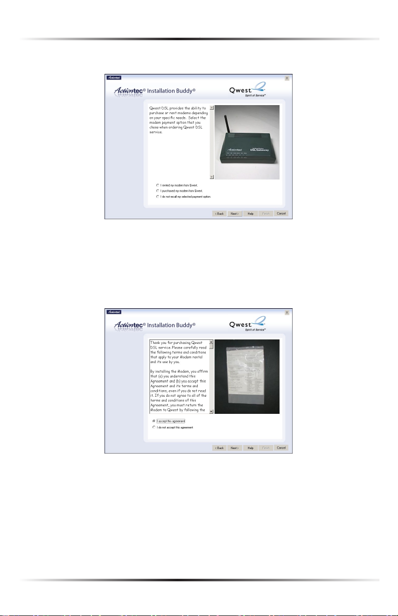
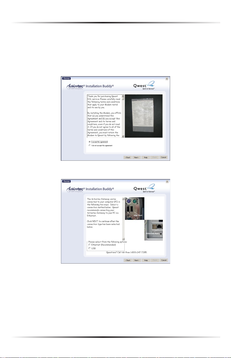
3. Select the appropriate modem payment option, then click Next.
4. Read the on-screen instructions regarding the terms and agreements of the
rental contract, click in the white circle next to I accept this agreement, then
click Next.
Note: If “I purchased my modem from Qwest” was selected in
☞
step 3, go directly to step 5.
11
Page 15
Actiontec 54 Mbps Wireless DSL Gateway User Manual
13
Chapter 2 Setting Up the Gateway
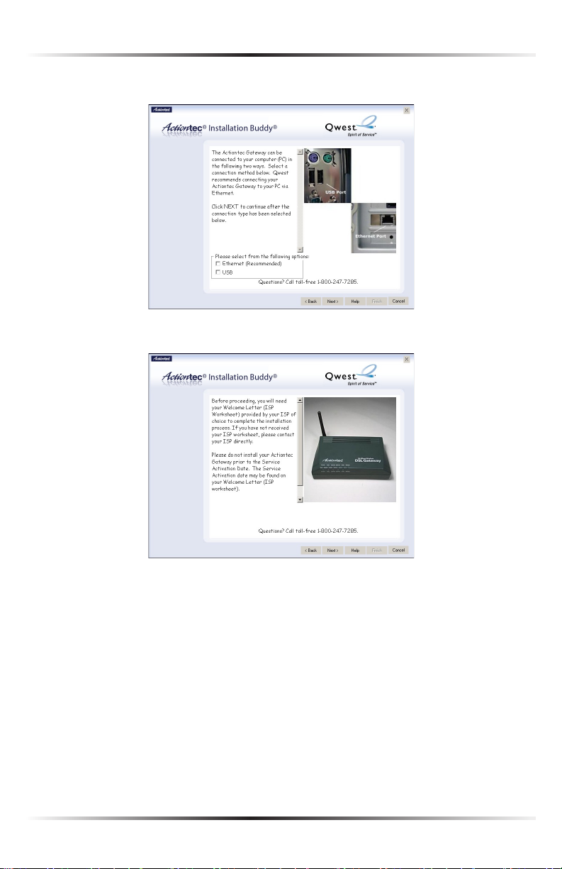
5. Click the check box next to Ethernet (Recommended), then click Next.
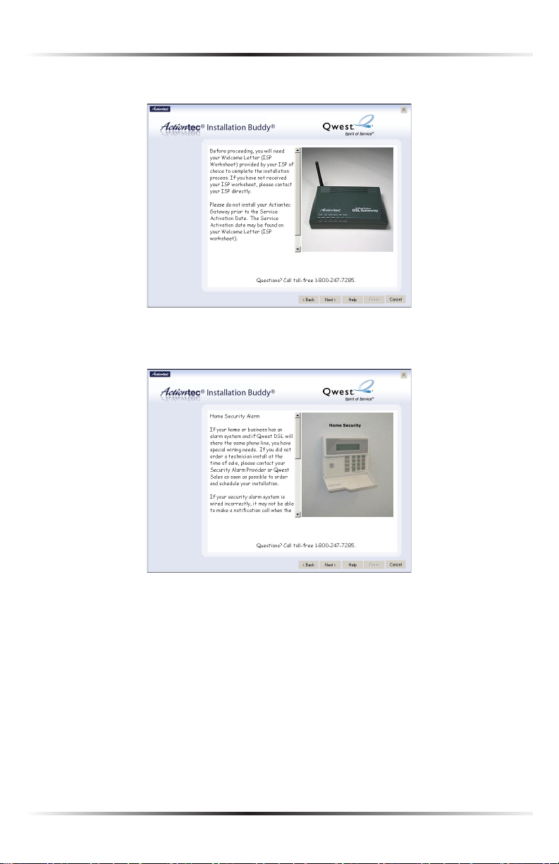
6. Get the Welcome Letter (or ISP Worksheet) provided by the ISP. Click Next.
12
Page 16
Chapter 2 Setting Up the Gateway
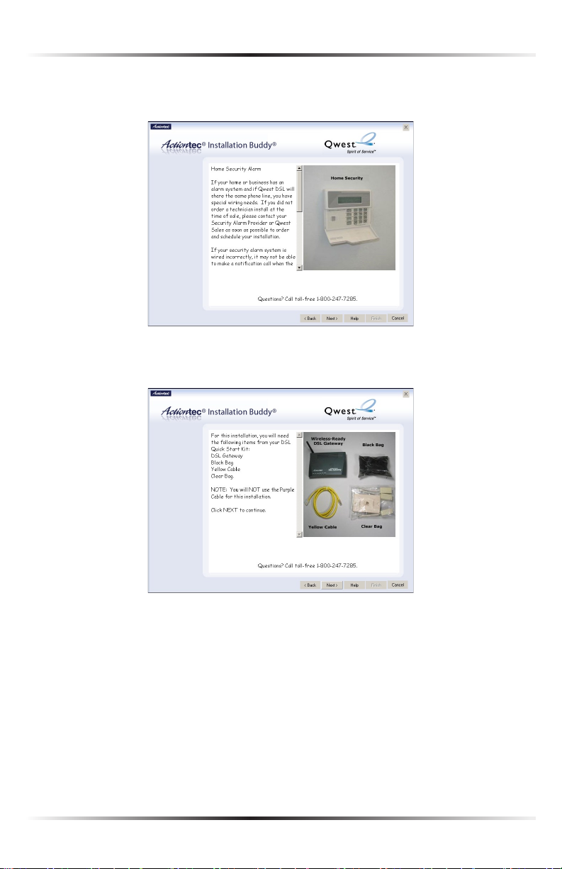
7. Read the on-screen information concerning home security alarms, then click
Next.
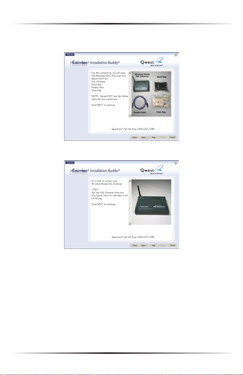
8. Make sure the items needed to connect the Gateway to the first computer on
included in the kit, then click Next.
13
Page 17
Actiontec 54 Mbps Wireless DSL Gateway User Manual
15
Chapter 2 Setting Up the Gateway
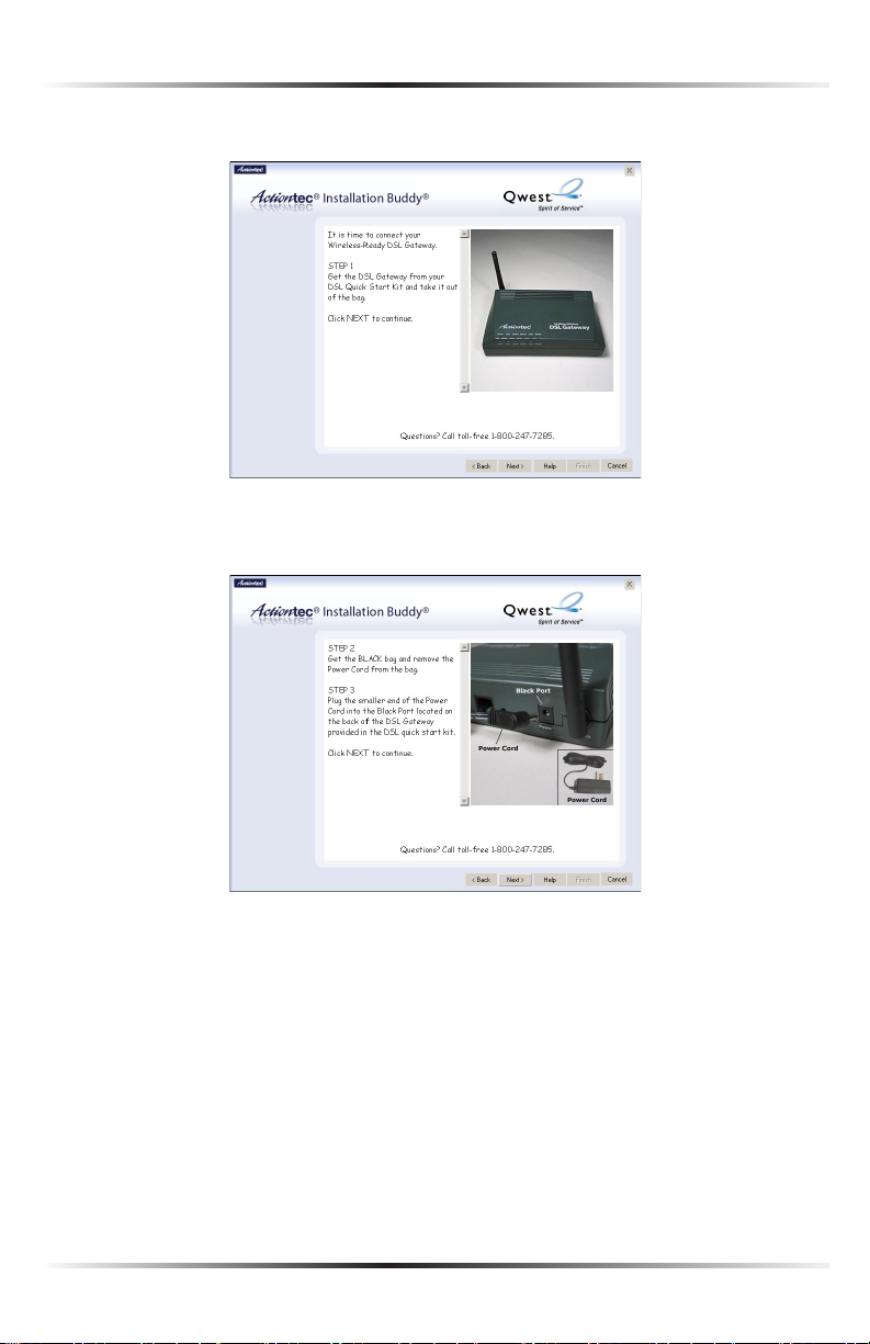
9. Get the Gateway from the kit, then click Next.
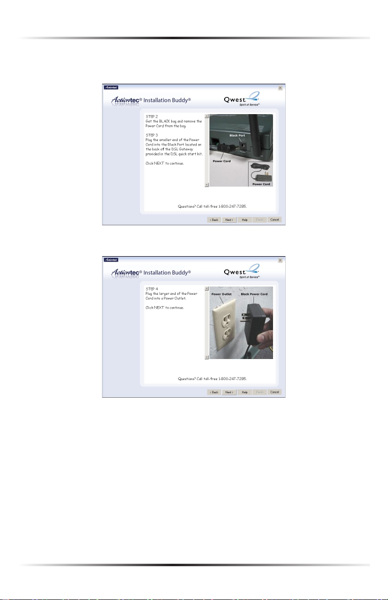
10. Get the Power cord from the black bag and plug the smaller end into the
black Power port on the rear panel of the Gateway, then click Next.
14
Page 18
Chapter 2 Setting Up the Gateway
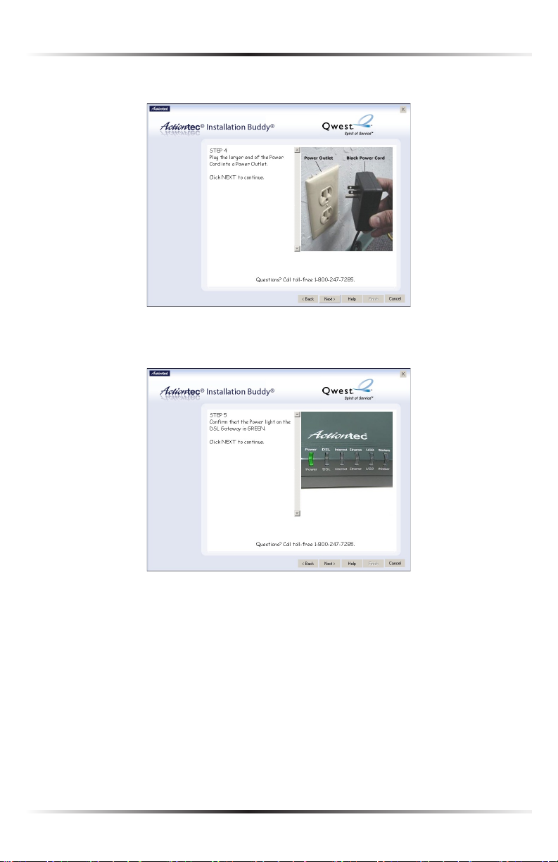
11. Plug the larger end of the Power cord into a power outlet, then click Next.
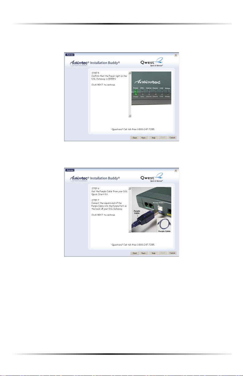
12. Confirm the Power light on the front of the Gateway glows solid green, then
click Next.
15
Page 19
Actiontec 54 Mbps Wireless DSL Gateway User Manual
17
Chapter 2 Setting Up the Gateway
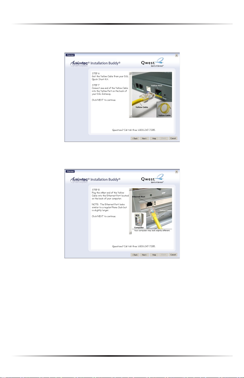
13. Get the yellow Ethernet cable from the kit and plug one end into a Yellow
port on the back of the Gateway, then click Next.
14. Plug the other end of the yellow Ethernet cable into an Ethernet port on
the back of the computer. Click Next.
Note: An Ethernet port looks similar to a phone jack, but is
☞
slightly larger.
16
Page 20

Chapter 2 Setting Up the Gateway
15. Make sure the Ethernet Network light on the front of the Gateway glows
solid green. Click Next.
16. Get the green cable from the kit and plug one end into the green Line port
on the rear panel of the Gateway. Click Next.
17
Page 21
Actiontec 54 Mbps Wireless DSL Gateway User Manual
19
Chapter 2 Setting Up the Gateway
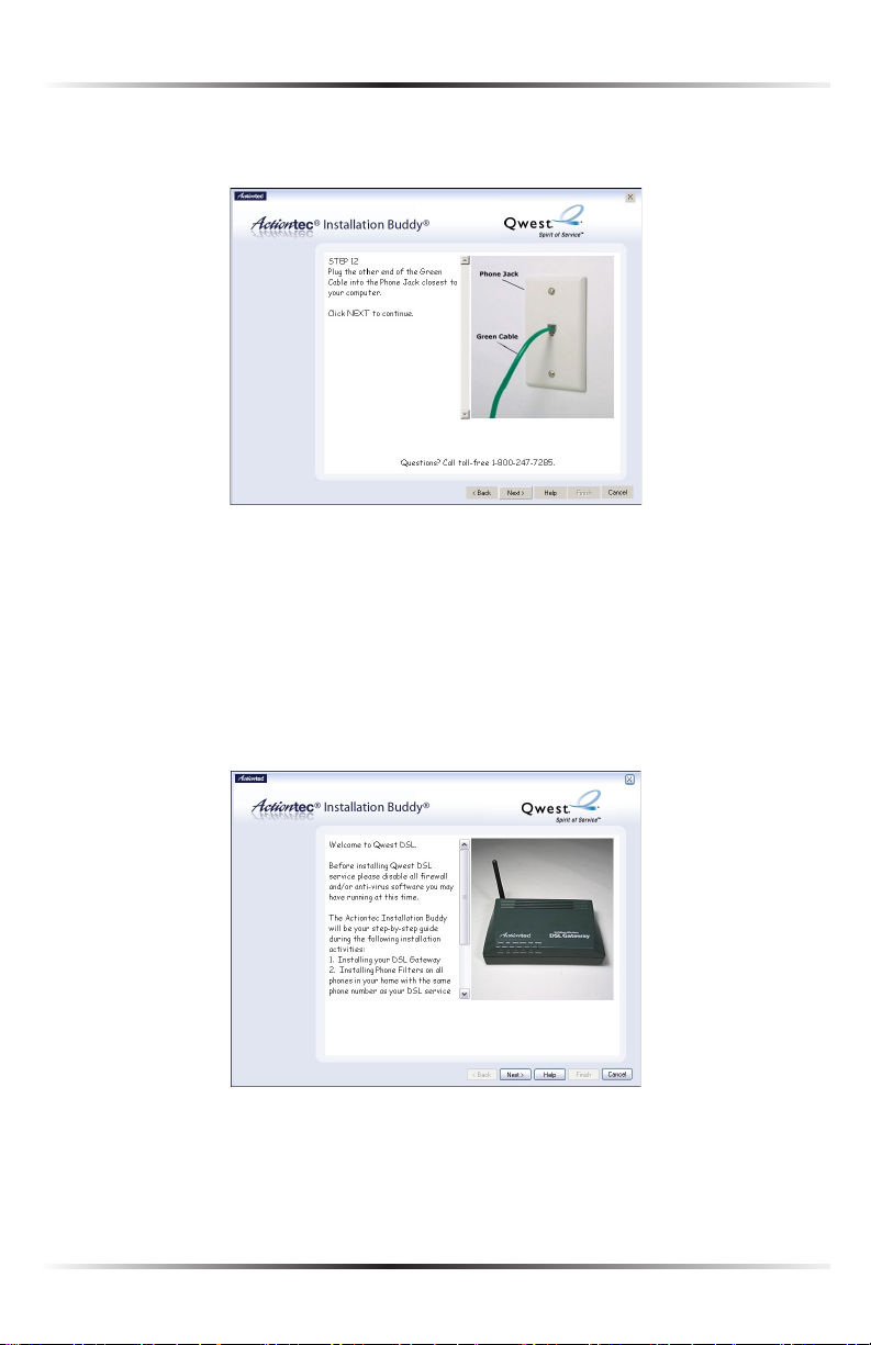
17. Plug the other end of the green cable into the phone jack closest to the com-
puter. Click Next.
The Gateway is connected to a computer via Ethernet. Next, install the filters as
described in “Installing Filters” on page 24.
Connecting Via USB
1. Insert the Installation CD in the CD-ROM drive of the computer. The
Installation Buddy will start automatically. Wait until the following screen
appears, read the on-screen instructions, then click Next.
18
Page 22
Chapter 2 Setting Up the Gateway
2. Read the instructions, select Initial Setup by clicking on the appropriate check
box, then click Next.
3. Select the appropriate modem payment option, then click Next.
19
Page 23
Actiontec 54 Mbps Wireless DSL Gateway User Manual
21
Chapter 2 Setting Up the Gateway
4. Read the on-screen instructions regarding the terms and agreements of the
rental contract, click in the white circle next to I accept this agreement, then
click Next.
Note: If “I purchased my modem from Qwest” was selected in
☞
step 3, go directly to step 5.
5. Click the check box next to USB, then click Next.
20
Page 24
Chapter 2 Setting Up the Gateway
6. Get the Welcome Letter (or ISP Worksheet) provided by the ISP. Click Next.
7. Read the on-screen information concerning home security alarms, then click
Next.
21
Page 25
Actiontec 54 Mbps Wireless DSL Gateway User Manual
23
Chapter 2 Setting Up the Gateway
8. Make sure the items needed to connect the Gateway to the first computer on
included in the kit, then click Next.
9. Get the Gateway from the kit, then click Next.
22
Page 26
Chapter 2 Setting Up the Gateway
10. Get the Power cord from the black bag and plug the smaller end into the
black Power port on the rear panel of the Gateway, then click Next.
11. Plug the larger end of the Power cord into a power outlet, then click Next.
23
Page 27
Actiontec 54 Mbps Wireless DSL Gateway User Manual
25
Chapter 2 Setting Up the Gateway
12. Confirm the Power light on the front of the Gateway glows solid green, then
click Next.
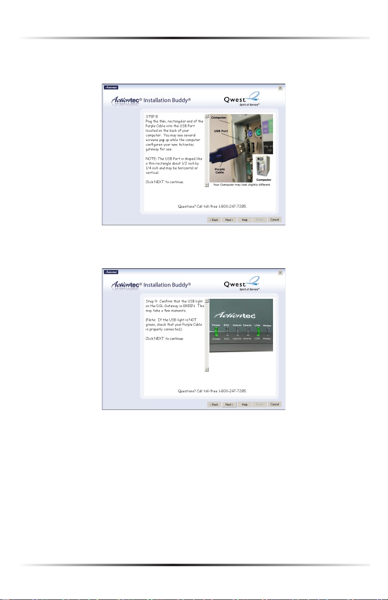
13. Get the purple USB cable from the kit and plug one end into the Purple port
on the back of the Gateway, then click Next.
24
Page 28
Chapter 2 Setting Up the Gateway
14. Plug the other end of the purple USB cable into a USB port on the front or
back of the computer. Click Next.
15. Make sure the USB light on the front of the Gateway glows solid green.
Click Next.
25
Page 29
Actiontec 54 Mbps Wireless DSL Gateway User Manual
27
Chapter 2 Setting Up the Gateway
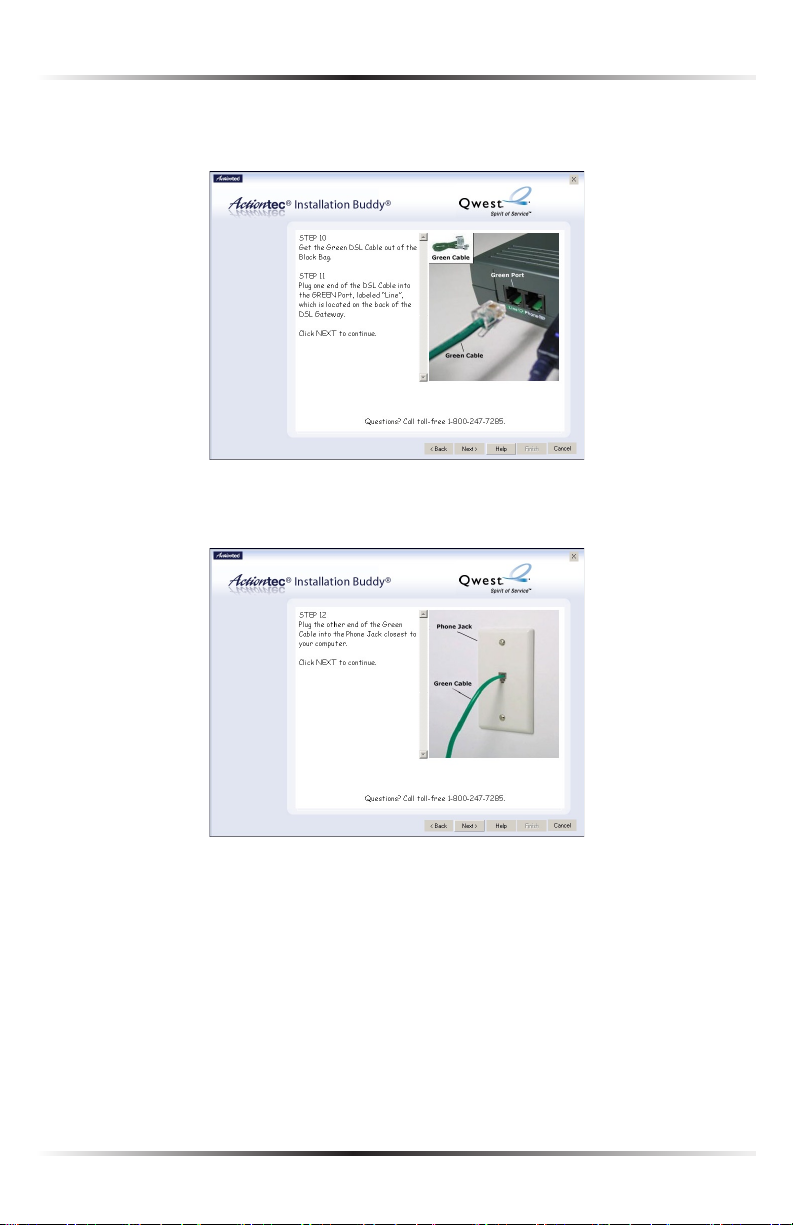
16. Get the green DSL cable from the kit and plug one end into the green Line
port on the rear panel of the Gateway. Click Next.
17. Plug the other end of the green DSL cable into the phone jack closest to the
computer. Click Next.
The Gateway is connected to a computer via USB. Next, install the filters as
described in “Installing Filters” on page 24.
26
Page 30
Chapter 2 Setting Up the Gateway
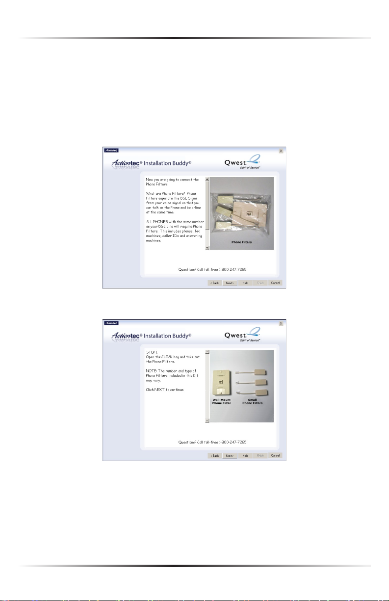
Installing Phone Filters
Phone filters allow the use of the telephone while online. All telephones and other
devices (answering machines, fax machines, etc.) using the same phone line (i.e.,
using the same phone number) as the DSL line must have a phone filter installed.
To install a filter, follow these instructions:
1. Read the on-screen information, get the Clear Bag, then click Next.
2. Remove the phone filters from the Clear Bag. Click Next.
27
Page 31

Actiontec 54 Mbps Wireless DSL Gateway User Manual
29
Chapter 2 Setting Up the Gateway
3. Read the on-screen information, then unplug all telephones and other devices from
their phone jacks. Click Next.
Caution: Do not unplug the green DSL cable from the phone
M
jack near your computer.
4. Plug a phone filter into every phone jack with a telephone or other device connected
to it, then plug the ends of the phone lines disconnected in step 3 into the
phone filters plugged into wall jacks. Click Next.
Caution: Do not plug a phone filter in the phone jack in which
M
the green DSL cable is plugged.
28
Page 32

Chapter 2 Setting Up the Gateway
5. If using a wall-mount phone, read the on-screen instructions, then click Next. If
not installing a wall-mount phone filter, go step 7.
6. Install a wall-mount phone filter by removing the wall-mount telephone and open-
ing the top and bottom toggles. Then, push the wall-mount filter onto the wall jack,
push the toggles back into the closed position, and remount the wall-mount telephone. Click Next.
29
Page 33

Actiontec 54 Mbps Wireless DSL Gateway User Manual
31
Chapter 2 Setting Up the Gateway
7. Answer the question (“Do you have a phone next to your computer?”) by
clicking on the appropriate check box, then click Next.
8. If you answered “No” in the previous window, go to “Setting up the DSL
Connection” on page 31. If you answered “Yes,” unplug the phone cord con-
nected to the telephone from its phone jack in the wall, then click Next.
Note: You may have already unplugged this phone cord.
☞
Caution: Do not unplug the green DSL cable from the phone
M
jack near your computer.
30
Page 34

Chapter 2 Setting Up the Gateway
9. Plug the phone cord into the Phone Jack on the back of the Gateway. The
connections should look like the configuration in the picture, below (if the
first computer is connected via Ethernet; if the first computer is connected via
USB, the purple cable will be plugged into the purple port). Click Next.
10. Read the on-screen information concerning automatic water meters, then
click Next.
31
Page 35

Actiontec 54 Mbps Wireless DSL Gateway User Manual
33
Chapter 2 Setting Up the Gateway
11. Make sure a phone filter is NOT connected to the green DSL cable, and that
the green DSL cable is connected as shown on-screen.
Ethernet:
USB:
32
Page 36

Chapter 2 Setting Up the Gateway
12. Make sure the appropriate lights on the front of the Gateway glows solid
green. Click Next.
Ethernet:
USB:
Next, go to “Setting Up the DSL Connection,” on the next page.
33
Page 37

Actiontec 54 Mbps Wireless DSL Gateway User Manual
35
Chapter 2 Setting Up the Gateway
Setting Up the DSL Connection
After connecting the Gateway and installing phone filters, the DSL connection
must be configured. To do this:
1. Read the on-screen instructions, choose the appropriate ISP option (indicated
in the Welcome Letter), then click Next.
If MSN is selected, go to step 2.
If Other IP is selected, go to step 4.
2. Read the on-screen rental agreement, and if you accept it, click the circle next
to “I accept the agreement.” Click Next.
34
Page 38

Chapter 2 Setting Up the Gateway
3. Enter the user name and password in the appropriate text boxes (or click the
check box next to “My ISP does not require this information.”), then click Next.
Then, go to step 8.
MSN users must enter their PPP User Name and PPP Password.
4. If Other ISP was selected in step 1, select the appropriate ISP protocol
(PPPoE, PPPoA, or RFC 1483), as indicated in the Welcome Letter.
If PPPoE or PPPoA is selected, got to step 5.
If RFC 1483 is selected, go to step 6.
35
Page 39

Actiontec 54 Mbps Wireless DSL Gateway User Manual
37
Chapter 2 Setting Up the Gateway
5. Enter the user name and password in the appropriate text boxes (or click the
check box next to “My ISP does not require this information.”), then click Next.
Then, go to step 9.
6. If RFC 1483 was selected in step 4, select the appropriate IP type. This infor-
mation is available in the Welcome Letter. When finished, click Next.
If Static IP is selected, go to step 7.
If Dynamic IP (DHCP) is selected, got to step 9.
36
Page 40

Chapter 2 Setting Up the Gateway
7. Select the type of Static IP address received from the ISP (Single or Block),
then click Next.
8. Enter the IP Address, Subnet, Gateway, DNS 1, and DNS 2 information
(if applicable) in the proper text boxes. This information is available in the
Welcome Letter. When finished, click Next.
Block of IP Addresses:
37
Page 41

Actiontec 54 Mbps Wireless DSL Gateway User Manual
39
Chapter 2 Setting Up the Gateway
Single IP Addresses:
9. The Installation Buddy checks the configuration of the Gateway.
38
Page 42

Chapter 2 Setting Up the Gateway
10. A “Congratulations” screen appears. Read the on-screen information, then
click through the next few windows to exit the Installation Buddy.
MSN:
Other ISPs:
The Gateway is successfully configured and ready for use.
39
Page 43

Actiontec 54 Mbps Wireless DSL Gateway User Manual
This page left intentionally blank.
40
Page 44

Using Qwest DSL
3
Qwest DSL operates over home or business phone lines equipped with Qwest
DSL service. For this reason, the Qwest DSL connection is not portable; it can’t be
accessed while away from the home or business. To connect while traveling, ask the
ISP about a dial-up account. Most Qwest DSL ISPs provide a dial-up account for
free, while others charge a minimal fee.
Qwest DSL is a highly reliable service, but it is possible to have a dial-up connection
in the unlikely event that problems arise with the DSL service. Most Qwest DSL ISPs
provide a dial-up account for free. If not, there are a number of free Internet providers whose products make great backup Internet access in the unlikely event they
are ever needed.
Connecting to the Internet
Whether connecting via Point-to-Point Protocol (PPPoE, PPPoA) or Bridging Mode
(RFC 1483), after connecting and configuring the Gateway, the Internet connection
is always on. Therefore, to connect or reconnect to the Internet, simply turn on
your computer, open the Web browser and go to the Web site of your choice. No
further set up is needed.
Disconnecting from the Internet
Closing the Web browser does not disconnect you from the Internet. To fully disconnect, turn off your computer.
41
Page 45

Actiontec 54 Mbps Wireless DSL Gateway User Manual
This page left intentionally blank.
42
Page 46

Basic Setup
4
This chapter is a guide through a basic configuration of the Gateway, including
how to connect the Gateway to the ISP.
To complete the basic setup, the user will need the Welcome Letter (ISP
Worksheet). If the document is not available, contact the ISP immediately.
Basic Setup
To configure the gateway for basic operation:
1. Open the Web browser. In the address bar, enter
http://192.168.0.1
then press Enter on the keyboard.
2. The “Main Menu” screen appears. Select Setup/Configuration.
43
Page 47

Actiontec 54 Mbps Wireless DSL Gateway User Manual
45
Chapter 4 Basic Setup
3. Follow the instructions in the “Set Up/Configuration” screen, then click Begin
Basic Setup.
4. In the next window, follow the on-screen instructions, then click Next.
5. In the next window, select the type of connection by clicking on the circle
next to PPPoA or PPPoE. If unsure about the selection, contact the ISP.
44
Page 48

Chapter 4 Basic Setup
6. Enter the User Name and Password provided by the ISP in the “DSL
Broadband Connection - PPP” screen. If the ISP provided a Static IP address,
enter it in the Static IP text box. If not, leave it blank. Click Next.
Note: If you obtained a block of Static IP addresses, see Chapter
☞
5, “Advanced Setup,” on page 35 to configure the Gateway.
7. Click Save and Restart in the “Save and Restart” screen.
8. The “Congratulations” screen appears. The Gateway is successfully configured.
The Power Light flashes rapidly while the Gateway restarts, then glows steadily
green when fully operational. The Internet Light will also glow steadily green. The
Gateway is now configured and users can start surfing the Web.
If an error stating the Web browser was unable to connect to the Internet appears,
check the configuration settings. Ensure all the information required by the ISP is
entered correctly.
45
Page 49

Actiontec 54 Mbps Wireless DSL Gateway User Manual
This page left intentionally blank.
46
Page 50

Setting Up Static IP Address
This chapter details how to set up the Gateway with a static IP address. The first
section explains the configuration using a single static IP address; the second section explains the configuration using a block of static IP addresses.
Configuring for a Single Static IP Address
To set up the Gateway to use a single static IP address:
Note: To complete this procedure, you must have access to the
☞
Internet Service Provider (ISP) worksheet. If no worksheet has
been provided, contact the ISP.
1. Open the Web browser. In the address bar enter:
http://192.168.0.1
then press Enter on the keyboard.
2. The “Main Menu” screen appears. Select Setup/Configuration.
5
47
Page 51

Actiontec 54 Mbps Wireless DSL Gateway User Manual
49
Chapter 5 Setting Up Static IP
Note: If the Main Menu screen does not appear, make sure the
☞
Ethernet cable is properly connected.
3. In the “Set Up/Configuration” screen, select Non-Windows Setup from the
menu on the left side.
4. The “Actiontec DSL Gateway Setup Page” screen appears. Using the Internet
Service Provider (ISP) worksheet, enter the following information:
ISP Protocol (select RFC1483 Bridged, RFC1483 Routed, PPPoA, or PPPoE
by clicking in the appropriate circle), ISP Username, ISP Password (in the
appropriate text boxes).
48
Page 52

Chapter 5 Setting Up Static IP
5. Scroll down to the IP Configuration section on the existing page, click on the
circle next to “Static,” and enter the IP address obtained from the ISP work-
sheet in the IP text box.
Note: The “Subnet” and “Gateway” text boxes are not used dur-
☞
ing this procedure.
6. If provided with DNS settings on the ISP worksheet, click the circle next to
“Static” and enter the DNS addresses in the “DNS Configuration” section at
the bottom of the Actiontec DSL Modem Setup Page screen.
If no DNS settings were provided, go to step 7.
7. Click “Save and Restart” at the bottom of the screen.
49
Page 53

Actiontec 54 Mbps Wireless DSL Gateway User Manual
51
Chapter 5 Setting Up Static IP
8. The “Save and Restart” page appears. Click “Save and Restart” to save the set-
tings changed in the Actiontec DSL Modem Setup Page screen.
9. Once the Gateway restarts, return to the Setup/Configuration screen and
select Change Admin Password from the menu on the left side.
10. The “Change Admin Password” screen appears. Enter a new password in the
“New Password” text box, and re-enter the password in the “Re-enter New
Password” text box. Make sure to write this password down and keep it in a
secure location. This password will be needed to access to the Gateway’s Web
setup screens.
11. Click “Save and Restart” at the bottom of the screen.
50
Page 54

Chapter 5 Setting Up Static IP
12. The “Save and Restart” page appears. Click “Save and Restart” to save the set-
tings changed in the Change Admin Password screen.
The Gateway has been configured to support a single static IP address. Once the
Power light stops blinking, the Gateway is ready for use.
Configuring for a Block of Static IP Addresses
To set up the Gateway to use a block of static IP addresses:
Note: To complete this procedure, you must have access to the
☞
Internet Service Provider (ISP) worksheet. If no worksheet has
been provided, contact the ISP.
1. Open the Web browser. In the address bar enter:
http://192.168.0.1
then press Enter on the keyboard.
2. The “Main Menu” screen appears. Select Setup/Configuration.
51
Page 55

Actiontec 54 Mbps Wireless DSL Gateway User Manual
53
Chapter 5 Setting Up Static IP
3. In the “Set Up/Configuration” screen, read the instructions, then select
Advanced Setup from the menu on the left side.
4. Click Begin Advanced Setup.
5. The “Configuring the Advanced Settings” screen appears. Select WAN
IP Address from the menu on the left side.
52
Page 56

Chapter 5 Setting Up Static IP
6. Select “Obtain an IP Address through PPPoA,” select “Unnumbered Mode,”
then enter the gateway and subnet mask addresses assigned by the ISP in the
“Gateway Address” and “Unnumbered Subnet Mask” text boxes, respectively.
These addresses should be included on the ISP worksheet. Click Next.
7. In the “Broadband Connection via PPPoA” screen, enter the user name and
password assigned by the ISP in the appropriate text boxes, then click Next
four times.
53
Page 57

Actiontec 54 Mbps Wireless DSL Gateway User Manual
55
Chapter 5 Setting Up Static IP
8. In the “DHCP Server Configuration” screen, select “Static” from the
“DNS” options near the center of the screen, then enter the DNS Server IP
addresses assigned by the ISP in the appropriate text boxes.
Note: If the ISP did not provide static DNS addresses, leave the
☞
DNS option at “Dynamic.” Also, if the DHCP server option
is turned off, this screen will not appear. The Gateway will
obtain dynamically assigned DNS addresses if supported by
the ISP with static IP addresses.
9. Click “Save and Restart” from the menu on the left side.
10. The “Save and Restart” page appears. Click “Save and Restart” to save the set-
tings.
11. Once the Gateway restarts, return to the Setup/Configuration screen and
select Change Admin Password from the menu on the left side.
54
Page 58

Chapter 5 Setting Up Static IP
12. The “Change Admin Password” screen appears. Enter a new password in the
“New Password” text box, and re-enter the password in the “Re-enter New
Password” text box. Make sure to write this password down and keep it in a
secure location. This password will be needed to access to the Gateway’s Web
setup screens.
13. Click “Save and Restart” at the bottom of the screen.
14. The “Save and Restart” page appears. Click “Save and Restart” to save the set-
tings changed in the Change Admin Password screen.
The Gateway has been configured to support a block of static IP addresses. Once
the Power light stops blinking, the Gateway is ready for use.
55
Page 59

Actiontec 54 Mbps Wireless DSL Gateway User Manual
This page left intentionally blank.
56
Page 60

Advanced Setup
6
This section contains information concerning advanced configuration, such as
wireless settings, remote management, and Web site blocking.
Accessing Advanced Setup
To access the Advanced Setup configuration screens, follow these instructions:
1. Open the Web browser. In the address bar enter:
http://192.168.0.1
then press Enter on the keyboard.
2. The “Main Menu” screen appears. Select Setup/Configuration.
3. In the “Set Up/Configuration” screen, read the instructions, then select
Advanced Setup from the menu on the left side.
Page 61

Actiontec 54 Mbps Wireless DSL Gateway User Manual
59
Chapter 6 Advanced Setup
4. In the next screen, read the recommendations. To perform an advanced setup
on the Gateway, click Begin Advanced Setup.
5. The “Configuring the Advanced Settings” screen appears. To check all the set-
tings, or if unsure of which settings to modify, select Next. To modify a specific configuration, click on its name in the menu bar on the left.
Note: To save changes made in any of the Advanced Setup
☞
screens, click Save and Restart at the bottom of the gray menu
on the left side of the screen.
WAN IP Address
Selecting WAN IP Address in the “Advanced Configuration” screen generates the
“WAN IP Address” screen. WAN IP Address allows manual set up of the IP address
of the Gateway. There are five ways to do this: Transparent Bridging, Obtain an
IP Address through PPPoE, Obtain an IP Address Through PPPoA, Obtain an IP
Address through DHCP, and Specify a Static IP Address.
58
Page 62

Chapter 6 Advanced Setup
Note: Some DSL providers use PPPoE/PPPoA to establish com-
☞
munication with an end user. Other types of broadband Internet
connections (such as fixed point wireless) may use either
DHCP or Static IP address. If unsure about which connection
is present, check with the Internet Service Provider (ISP) before
continuing.
After selecting a connection type, click Next to continue configuring the connection.
Transparent Bridging
Select this option to use the Gateway as a transparent bridge. This option should
only be used if the Gateway is being used as a Modem to connect one computer to
the Internet via a DSL connection. When the Gateway is being used as a transparent bridge, it does not provide any firewall security.
59
Page 63

Actiontec 54 Mbps Wireless DSL Gateway User Manual
61
Chapter 6 Advanced Setup
Obtain an IP Address through PPPoE or PPPoA
Select one of these options to allow the Gateway to use the Point-to-Point over
Ethernet (PPPoE) or Point-to-Point over ATM (PPPoA) protocol.
If a User Name, Password and/or Static IP was entered during Basic Setup, it
should be displayed in the “Broadband Connection via PPPoE/PPPoA” screen.
If not, enter the information now. If the information is unavailable, contact the
Internet Service Provider (ISP).
PPP Auto Connect
If PPP auto connect is activated (by clicking in the appropriate check box), the
Gateway will attempt to automatically redial the PPP connection if it is dropped
or disconnected during an online session.
Obtain an IP Through DHCP
Select this option if the IP service is configured to use RFC 1483 Bridged or Routed
(used for configurations without a Static IP assigned by an ISP). In this mode, the
Gateway will query the Internet Service Provider (ISP) to receive the IP address
and routing information, which will terminate at the Gateway, as opposed to the IP
address and routing information being bridged to terminate at the computer. This
allows the use of the router capabilities for the Local Area Network (LAN).
Some ISPs need to authenticate their end users with a Host Name and/or Domain
Name. If this is the case, check with the ISP for a host name and domain name and
enter them in the “Broadband Connection via DHCP” screen. If the ISP does not
require these settings, leave the text boxes blank.
60
Page 64

Chapter 6 Advanced Setup
Note: Contact the ISP if unsure of the proper configuration.
☞
Specify a Static IP Address
Select this option if the ISP service is configured to use RFC 1483 Bridged or
Routed using a Static IP Address. Enter the IP Address, Subnet Mask, and Default
Gateway Address provided by the ISP in the “Broadband Connection via Static
IP Address” screen, which causes the IP address and routing information to termi-
nate at the Gateway, as opposed to the IP address and routing information being
bridged to terminate at the computer. This allows the use of the router capabilities
for the Local Area Network (LAN).
Note: Contact the ISP if unsure of the proper configuration.
☞
61
Page 65

Actiontec 54 Mbps Wireless DSL Gateway User Manual
63
Chapter 6 Advanced Setup
Encapsulation
If the Gateway is configured to obtain an IP address through DHCP or to specify a
static IP address, select the appropriate encapsulation option used by the ISP (RFC
1483 Bridged or RFC 1483 Routed).
Note: Contact the ISP if unsure of the proper configuration.
☞
Unnumbered Mode/VIP Mode
If a block of public static IP addresses was purchased from the ISP, select
Unnumbered Mode by clicking in the appropriate check box. Then, enter the IP
Address and Subnet Mask in the “Gateway Address” and “Unnumbered Subnet
Mask” text boxes below the “Unnumbered IP Address.” Click Next, then click Save
and Restart to make all changes permanent.
The Unnumbered Mode feature automatically configures the appropriate IP routing for the IP Address block. The IP route will bypass NAT, enabling the public IPs
to be routed WAN-to-LAN, as well as LAN-to-WAN.
Note: The IP Address information should be obtained from the
☞
ISP when purchasing a block of public static IP address. Contact
the ISP if this information was not received.
62
Page 66

Chapter 6 Advanced Setup
VIP Mode - This feature is used in conjunction with Unnumbered Mode. When
VIP Mode is activated, the Gateway uses NAT for private IP Addressing for the Local
Area Network (LAN), allowing both Public IP Addressing and Private IP Addressing to
be configured to the LAN simultaneously, while the DHCP server is reserved for Private
IP Addressing. All computers using Public IP Addresses with Unnumbered Mode must
have the Public IP Addresses statically assigned.
After configuring your settings, click Next, then click Save and Restart to make all
changes permanent.
Wireless Settings
Selecting Wireless Settings in the “Advanced Configuration” screen generates the
“Wireless Settings” screen. To activate the wireless “radio” of the Gateway, click in
the circle next to “On.” To turn it off, click in the circle next to “Off.”
ESSID
ESSID is the network name assigned to the wireless network. The factory default
setting is “ACTIONTEC.” Although Actiontec recommends keeping the default
value intact, the ESSID value can be modified, using any combination of alphanu-
meric characters (i.e., A-Z, a-z, 0-9). All wireless-capable computers included on
the Gateway’s wireless network must have this same ESSID value. (For the Actiontec
802.11b Wireless PC Card, the ESSID value must be the same as the SSID value.)
63
Page 67

Actiontec 54 Mbps Wireless DSL Gateway User Manual
65
Chapter 6 Advanced Setup
Channel
Channel assigns the frequency band at which the Gateway communicates. In the
United States, use channels 1-11. (The factory default value is set to 1.)
Security
There are four wireless security options: Off, WEP, WEP+802.1x, and WPA. The
latter three options are different types of wireless security.
Off
Selecting Off disables wireless security. Selecting this option allows any computer
with wireless capability and the correct ESSID value to join the wireless network.
WEP
Selecting the security option “WEP” in the Wireless Settings screen generates the
“WEP Key” screen. Here, the authentication type, encryption level, and WEP
keys are entered to activate WEP (Wired Equivalent Privacy) security encryption
for the wireless network.
Authentication Type - There are three authentication types: Open, Shared, and
Both. Open authentication allows any wireless-enabled device to recognize the
Gateway, if the correct WEP key is enabled on the device. Shared allows only
wireless-enabled devices with the correct WEP key and Shared key to recognize
the Gateway. Selecting Both enables both Open and Shared authentication types.
64
Page 68

Chapter 6 Advanced Setup
64-bit WEP - 64-bit WEP requires four separate keys. Each key comprises five hexa-
decimal digit pairs. A hexadecimal digit consists of an alphanumeric character
ranging from 0-9 or A-F. An example of a 64-bit WEP key is: 4E-A3-3D-68-72. To
create a set of 64-bit WEP keys, activate all four keys by clicking in the appropriate circles, then enter five hexadecimal digit pairs in each Key text box (Key 1-,
Key 2-, Key 3-, Key 4-). After activating 64-bit WEP on the Gateway, a computer
with wireless capability can join the network only if these same keys are entered
in the computer’s wireless encryption scheme.
128-bit WEP - 128-bit WEP requires one key, comprising 13 hexadecimal pairs. A
hexadecimal digit consists of alphanumeric characters ranging from 0-9 or A-F.
An example of a 128-bit WEP key is: 3D-44-FE-6C-A1-EF-2E-D3-C4-21-74-5D-B1. To
create a 128-bit WEP key, activate Key 1 by clicking in the appropriate circle, then
enter 13 hexadecimal digit pairs in the Key text box. After activating 128-bit WEP
on the Gateway, a computer with wireless capability can join the network only if
this key is entered in the computer’s wireless encryption scheme.
256-bit WEP - 256-bit WEP requires one key, comprising 29 hexadecimal pairs. A
hexadecimal digit consists of alphanumeric characters ranging from 0-9 or A-F.
An example of a 256-bit WEP key is: 3D-44-FE-6C-A1-EF-2E-D3-C4-21-74-5D-B1. To
create a 256-bit WEP key, activate Key 1 by clicking in the appropriate circle, then
enter 29 hexadecimal digit pairs in the Key text box. After activating 256-bit WEP
on the Gateway, a computer with wireless capability can join the network only if
this key is entered in the computer’s wireless encryption scheme.
Note: Not all wireless PC Cards support 128- or 256-bit WEP.
☞
Ensure that all PC Cards installed in the networked computers
support 128- or 256-bit WEP before activating.
65
Page 69

Actiontec 54 Mbps Wireless DSL Gateway User Manual
67
Chapter 6 Advanced Setup
WEP+802.1x
Activating WEP+802.1x and clicking Next in the Wireless Settings screen generates the “Wireless 802.1x Security Settings” screen. This setting is for enterprise
networks only, and should be accessed by experienced information systems specialists only.
To set up WEP+802.1x security, enter the IP address of the RADIUS server in the
“Server IP Address” text box, and the “Secret” key (for communication between
the RADIUS server and the Router) in the “Secret” text box. The “Port” and
“Group Key Interval” values should remain the same
WPA
Activating WPA (Wi-Fi Protected Access) and clicking Next in the Wireless
Settings screen generates the “Wireless WPA Settings” screen.
There are two levels of WPA. The “Group Key Interval,” “Server IP Address,”
“Port,” and “Secret” text boxes, along with the “802.1x” radio button, are enter-
prise network specific, and should only be accessed by an experienced information systems professional. See “WEP+802.1x” on the previous page for more
information.
66
Page 70

Chapter 6 Advanced Setup
“PSK String” is for home network security. To set up a PSK (Pre-Shared Key),
click in the circle next to PSK String, then enter at least eight alphanumeric
characters in the text box. All wireless-enabled devices must support WPA and
know the PSK to join the network.
Important: Wireless networking devices use public radio chan-
P
nels to transmit voice and data communications. Although WEP
is the standard security technology used today and offers some
degree of security, Qwest cannot guarantee the security, privacy,
or confidentiality of any transmissions made via such devices,
and Qwest makes no assurances or warranties relating to their
use by you. You are responsible for all use of your Qwest DSL ser-
vice, regardless of the source of a transmission, whether by you
or an authorized third party, over your Qwest DSL service.
Wireless MAC Authentication
Selecting Wireless MAC Authentication in the “Advanced Configuration” screen
generates the “Wireless MAC Authentication” screen.
This feature allows the user to control the Wireless LAN Network by denying or
allowing wireless access by specifying the MAC Address of the wireless client(s)
allowed or denied on the wireless network
After changing settings, click Next or Back to continue, or Save and Restart to
make all changes permanent.
67
Page 71

Actiontec 54 Mbps Wireless DSL Gateway User Manual
69
Chapter 6 Advanced Setup
LAN IP Address
Selecting LAN IP Address in the “Advanced Configuration” screen generates the
“LAN IP Address” screen.
The values in the “LAN IP Address” and “Netmask” text boxes are the IP address
and Subnetmask of the Gateway as seen on the network. These values can be
modified for your LAN network, but Actiontec recommends keeping the default
factory settings (IP Address 192.168.0.1 Subnetmask 255.255.255.0).
Note: If the Gateway’s LAN IP Address is modified, verify the
☞
DHCP Server range is within the same subnet. For more infor-
mation, see “DHCP Server Configuration.”
After changing settings, click Next or Back to continue, or Save and Restart to
make all changes permanent.
DHCP Server
Selecting DHCP Server in the “Advanced Configuration” screen generates
the “DHCP Server” screen. The Gateway has a built-in DHCP (Dynamic Host
Configuration Protocol) server that automatically assigns a different IP address to
each computer on the network, eliminating IP address conflicts.
The factory default setting is On. To disable the DHCP Server, select Off.
68
Page 72

Chapter 6 Advanced Setup
Actiontec strongly recommends leaving the DHCP Server option On. If the DHCP
Server option is Off, ensure the IP addresses of the networked computers are
on the same subnet as the IP address of the Gateway. For more information, see
“DHCP Server Configuration.”
DHCP Server Configuration
Clicking Next in the “DHCP Server” screen generates the “DHCP Server
Configuration” screen. Change IP address range and DNS server information here.
Beginning IP Address - the IP address at which the DHCP server starts
assigning IP addresses. Actiontec recommends keeping the fac-
tory default setting (192.168.0.2).
Ending IP Address - the IP Address at which the DHCP Server stops
assigning IP addresses. Actiontec recommends keeping the fac-
tory default settings (192.168.0.254).
The beginning and ending IP addresses define the IP address range of the
Gateway. If the default values are left intact, the Gateway supplies a unique IP
address between 192.168.0.2 and 192.168.0.254 to each computer on the network. Note that the first three groups of numbers of the addresses are identical;
this means they are on the same subnet. The IP address of the Gateway must
be on the same subnet as the IP address range it generates. For instance, if the
Gateway’s IP address is changed to 10.33.222.1, set the beginning IP address to
10.33.222.2, and the ending IP address to 10.33.222.254.
DNS (Dynamic or Static) - the type of DNS server provided by the
Internet Service Provider (ISP). If the ISP provided DNS server
information, select the type here. If not, leave as is.
69
Page 73

Actiontec 54 Mbps Wireless DSL Gateway User Manual
71
Chapter 6 Advanced Setup
DNS Server 1 - the primary DNS server provided by the Internet
Service Provider (ISP). If the ISP provided DNS server informa-
tion, enter it here. If not, leave the text box intact.
DNS Server 2 - the secondary DNS provided by the Internet Service
Provider (ISP). If the ISP provided secondary DNS server infor-
mation, enter it here. If not, leave the text box intact.
Services Blocking
Selecting Services Blocking in the “Advanced Configuration” screen generates the
“Services Blocking” screen.
To modify Internet privileges (Web, FTP, Newsgroups, etc.) for the computers on
the network:
1. Enter the computer’s IP address in the IP Address: text box.
2. Select the Internet service(s) to be blocked.
3. Click Add to enter the computer’s IP address in the “Blocked IP Address List”
text box.
4. To remove blocked services, select the computer’s IP address in the “Blocked
IP Address List” text box and click Remove.
70
Page 74

Chapter 6 Advanced Setup
Netmeeting
If a computer on the network uses Netmeeting, enable Netmeeting, by clicking the
circle next to “On” and entering the IP address of the computer. Click Next, then
click Save and Restart to apply the settings. If Netmeeting is not needed, click the
circle next to “Off.”
Note: Netmeeting is used for NAT/Private IP addressing only. If
☞
the computer is configured for Unnumbered Mode and has a
Public IP Address, Netmeeting does not have to be enabled.
Website Blocking
Selecting Website Blocking in the “Advanced Configuration” screen generates the
“Website Blocking” screen. This feature enables the Gateway to block Web sites to
all computers on the network. To block a Web site, enter the address of the Web
site in the “Website” text box and click Add. The blocked Web site address will be
displayed in the “Blocked Website List” text box, and will not be available to computers on the network. To remove a blocked Web site, click on it in the “Blocked
Website List,” then click Remove.
71
Page 75

Actiontec 54 Mbps Wireless DSL Gateway User Manual
73
Chapter 6 Advanced Setup
Remote Management
Selecting Remote Management in the “Advanced Configuration” screen gener-
ates the “Remote Management” screen. Remote Management allows access to the
Gateway through the Internet via another computer. Actiontec recommends leav-
ing the Remote Management Off (the factory default setting).
To access the Gateway from the Internet, activate Remote Management by selecting
On and writing down the WAN IP address of the Gateway (see “WAN IP Address”).
On a computer outside of the network, open a Web browser and enter the
Gateway’s WAN IP address in the address text box. The Gateway’s Main Menu (or a
password prompt, if a password has been set) appears in the browser window.
Note: Before Remote Management can be activated, the admin-
☞
istrator password must be set. To do this, go to the Setup screen
and select Change Admin Password. Follow the instructions in
the subsequent screens
72
Page 76

Chapter 6 Advanced Setup
Port Forwarding
Selecting Port Forwarding in the “Advanced Configuration” screen generates the
“Port Forwarding” screen. Port forwarding allows certain programs to bypass the
Gateway’s built-in firewall, allowing access to parts of the network (for hosting a
Web or ftp server, for example). To use port forwarding, enter the IP port range in
the “IP Port Range” text boxes. (If more than 10 ports are needed, Actiontec recom-
mends using DMZ Hosting. See “DMZ Hosting,” below, for more information.)
Choose the protocol type from the “Protocol” list box, then enter the IP address of
the computer on the network to be used as a host. Click Add. The forwarded ports
appear in the “List of Forwarded Ports” text box.
To remove forwarded ports, highlight them, then click Remove.
Clicking Advanced brings up the “Advanced Port Forward” screen.
73
Page 77

Actiontec 54 Mbps Wireless DSL Gateway User Manual
75
Chapter 6 Advanced Setup
In this screen, the user can allow only certain IP addresses to access forwarded
ports. Enter the port range of the forwarded ports in the “Remote IP Port
Range” text boxes, enter the IP address to be allowed access in the “Remote
IP Address” text box, then click “Add.” The active forwarded ports will appear in
the “List of Forwarded Ports” text box.
To deactivate a forwarded port, select it from the “List of Forwarded Ports” text
box, then click “Remove.”
DMZ Hosting
Selecting DMZ Hosting in the “Advanced Configuration” screen generates the
“DMZ Hosting” screen. To use DMZ hosting, enter the IP address of the computer
on the network to be used as a DMZ host in the “DMZ Host IP Address” text box,
then click On.
DMZ hosting is used to support online gaming and Internet conferencing services.
These programs usually require multiple open ports, making the network accessible from the Internet. DMZ hosting symbolically places the DMZ host computer
outside of the Gateway’s network. Access to the network resources while DMZ
hosting is active is blocked. Actiontec recommends activating DMZ hosting only as
long as necessary.
Warning: The DMZ Host computer will be vulnerable to com-
M
puter hackers on the Internet while in DMZ mode.
74
Page 78

Chapter 6 Advanced Setup
Firewall
Selecting Firewall in the “Advanced Configuration” screen generates the “Firewall
Security Level” screen. Select the level of security needed for the network. See
Appendix E for details concerning each level of security.
Dynamic Routing
Selecting Dynamic Routing in the “Advanced Configuration” screen generates the
“Dynamic Routing” screen.
If a gateway is set up behind the Gateway in the network configuration, consult the
documentation that came with the gateway to see what kind of Dynamic Routing
is required, then select the needed option.
75
Page 79

Actiontec 54 Mbps Wireless DSL Gateway User Manual
77
Chapter 6 Advanced Setup
NAT (Network Address Translation)
Selecting NAT in the “Configuring the Advanced Settings” screen generates the
“NAT” screen. The Gateway’s basic firewall security is based on NAT. Disabling
NAT allows the computers connected to the Gateway to be accessed by outside
parties. Do not turn NAT off unless instructed to do so by the Internet Service
Provider (ISP).
Static Routing
Selecting Static Routing in the “Advanced Settings” screen generates the “Static
Routing” screen. Enter the addresses in their respective text boxes, then click Add.
The address will appear in the “Static Routing Table.” To remove an address, highlight it by clicking on it in the Static Routing Table, then click Remove.
76
Page 80

Chapter 6 Advanced Setup
Status
After configuring the Gateway, settings can be viewed by selecting Status in
the Main Menu. The “Current Status” screen appears, displaying many of the
Gateway’s settings. No settings (other than connecting or disconnecting from the
Internet) can be changed from the Current Status screen.
Firmware Version
Displays the firmware version the Gateway is currently running.
MAC Address
Displays the MAC (Media Access Control) address of the Gateway.
WAN - Connection
Displays the state of the connection to the ISP service (Connected or
Disconnected).
WAN - Mode
Displays the type of connection used to communicate with the ISP.
77
Page 81

Actiontec 54 Mbps Wireless DSL Gateway User Manual
79
Chapter 6 Advanced Setup
WAN - IP Address
Displays the IP Address the ISP assigned to the Gateway.
WAN - Subnet Mask
Displays the Subnet Mask address the ISP assigned to the Gateway.
WAN - Gateway
Displays the Gateway address (for the IP Address and Subnet Mask) the ISP
assigned to the Gateway.
WAN - DNS #1 & #2
Displays the Domain Name Server address(es) the ISP assigned to the Gateway.
LAN - IP Address
Displays the Local Area Network’s (LAN) IP address.
LAN - Net Mask
Displays the Subnet Mask address configured for the LAN IP address.
LAN - DHCP Server
Displays the state of the DHCP Server (On or Off).
In the left hand column, there are other Status options available: Routing Table,
WAN Status, LAN Status, and Active User List. Click to generate the option of
choice.
78
Page 82

Chapter 6 Advanced Setup
Routing Table
Selecting Routing Table generates the “Routing Table” screen. This screen displays
on overview of the Gateway’s routes.
WAN Status
Selecting WAN Status generates a “Current Status” screen. This screen displays on
overview of the Gateway’s WAN (Wide Area Network) connection.
79
Page 83

Actiontec 54 Mbps Wireless DSL Gateway User Manual
LAN Status
Selecting LAN Status generates the “Lan Port Status” screen. This screen displays
on overview of the Gateway’s LAN (Local Area Network) port connections.
Active User List
Selecting Active User List generates the “Active User List” screen. This screen dis-
plays a list of the users currently connected to the Gateway accessing the Internet
with Network Address Translation (NAT) security activated.
80
Page 84

Using Utilities
7
To access the Gateway’s Web-based Utilities, select Utilities from the “Main Menu”
screen. The “Utilities” screen appears.
From this screen, the Web activity log can be viewed, the DSL settings changed, the
Gateway’s factory default settings restored, and the Gateway’s firmware upgraded.
Web Activity Log
The Web Activity Log provides information about the Web sites each computer
on the Gateway’s network has visited. To access the Web Activity Log, select Web
Activity Log from the “Utilities” screen.
81
Page 85

Actiontec 54 Mbps Wireless DSL Gateway User Manual
83
Chapter 7 Using Utilities
Auto Refresh
To set the Web Activity Log screen to automatically refresh at certain intervals, activate the circle next to “Auto Refresh Every” at the bottom of the Web Activity Log
screen, then enter a time value (in seconds) in the text box, or click on the down
arrow and select a time value from the menu that appears. The Web Activity Log
will refresh at the chosen interval.
Manual Refresh
To set the Web Activity Log screen to manual refresh, activate the circle next to
“Manual Refresh” at the bottom of the Web Activity Log screen. To refresh the Web
Activity Log screen, click Refresh.
DSL Settings
To access DSL Settings, select DSL Settings from the “Utilities” screen. The
Gateway’s VPI, VCI, Mode, and QoS (Quality of Service) settings can be changed
from this screen. Actiontec recommends not changing these values without con-
sulting the ISP.
82
Page 86

Chapter 7 Using Utilities
Restore Default Settings
To restore the Gateway to its factory default settings, select Restore Default Settings
from the “Utilities” screen. When the “Restore Default Settings” screen appears,
click Restore Default Settings. Any changes made to the Gateway’s settings in the
Custom Setup screens will be lost and the factory default settings will be restored.
During this process, the Gateway’s Power Light flashes and the Gateway is disabled.
Warning: Do not unplug the power cord from the Gateway
N
during the Restore Default Settings process. Doing so may result
in permanent damage to the Gateway.
When the Power Light stops flashing and glows steadily green, the Gateway is fully
operational.
Upgrade Firmware
Selecting Upgrade Firmware in the “Utilities” screen generates the “Upgrade
Firmware” screen. Actiontec periodically posts firmware upgrades to enhance the
Gateway’s capabilities. Follow the instructions on-screen to upgrade the Gateway’s
firmware.
83
Page 87

Actiontec 54 Mbps Wireless DSL Gateway User Manual
This page left intentionally blank.
84
Page 88

Setting Up a Network
8
Other computers can be connected to the Gateway to form a network. The network computers can be connected to the Gateway in two ways: Ethernet or USB.
Ethernet
1. Insert the Installation CD in the CD-ROM drive of the computer. The
Installation Buddy will start automatically. Wait until the following screen
appears, read the on-screen instructions, then click Next.
2. Read the instructions, select Adding Computers by clicking on the appropriate
check box, then click Next.
85
Page 89

Actiontec 54 Mbps Wireless DSL Gateway User Manual
87
Chapter 8 Setting Up a Network
3. Select Ethernet, then click Next.
4. Read the on-screen instructions, choose the appropriate ISP option (indicated
in the Welcome Letter), then click Next.
If MSN is selected, go to step 5.
If Other IP is selected, go to step 6.
86
Page 90

Chapter 8 Setting Up a Network
5. Read the on-screen rental agreement, and if you accept it, click the circle next
to “I accept the agreement.” Click Next.
6. When the next window appears, get the Yellow Ethernet Cable from the
Quick Start Kit, then click Next.
87
Page 91

Actiontec 54 Mbps Wireless DSL Gateway User Manual
89
Chapter 8 Setting Up a Network
7. Plug one end of the Yellow Ethernet Cable into the Yellow Port on the back
of the Gateway, then click Next.
8. Plug the other end of the Yellow Ethernet Cable into an Ethernet port on
the back of the computer, then click Next.
Note: An Ethernet port looks similar to a phone port, but is
☞
slightly bigger.
88
Page 92

Chapter 8 Setting Up a Network
9. Make sure one of the Ethernet Network Lights glow steadily green, then click
Next.
10. In the next window, the Installation Buddy checks the configuration of the
Gateway.
89
Page 93

Actiontec 54 Mbps Wireless DSL Gateway User Manual
91
Chapter 8 Setting Up a Network
11. A congratulations window appears. The computer is connected to the network
via Ethernet.
MSN:
Other ISPs:
90
Page 94

Chapter 8 Setting Up a Network
USB
1. Insert the Installation CD in the CD-ROM drive of the computer. The
Installation Buddy will start automatically. Wait until the following screen
appears, read the on-screen instructions, then click Next.
2. Read the instructions, select Adding Computers by clicking on the appropriate
check box, then click Next.
91
Page 95

Actiontec 54 Mbps Wireless DSL Gateway User Manual
93
Chapter 8 Setting Up a Network
3. Select USB, then click Next.
4. Read the on-screen instructions, choose the appropriate ISP option (indicated
in the Welcome Letter), then click Next.
If MSN is selected, go to step 5.
If Other IP is selected, go to step 6.
92
Page 96

Chapter 8 Setting Up a Network
5. Read the on-screen rental agreement, and if you accept it, click the circle next
to “I accept the agreement.” Click Next.
6. When the next window appears, get the purple USB Cable from the Quick
Start Kit, then click Next.
93
Page 97

Actiontec 54 Mbps Wireless DSL Gateway User Manual
95
Chapter 8 Setting Up a Network
7. Plug the square end of the purple USB Cable into the Purple Port on the
back of the Gateway, then click Next.
8. Plug the other end of the purple USB Cable into an USB port on the front
or back of the computer, then click Next.
94
Page 98

Chapter 8 Setting Up a Network
9. Make sure the Power, Internet, and USB Lights glow steadily green, then
click Next.
10. In the next window, the Installation Buddy checks the configuration of the
Gateway.
95
Page 99

Actiontec 54 Mbps Wireless DSL Gateway User Manual
11. A congratulations window appears. The computer is connected to the network
via USB.
MSN:
Other ISPs:
96
Page 100

Troubleshooting
9
This chapter contains a list of problems that may be encountered while using the
Gateway, and techniques to try and overcome the problem. Note that these techniques may not solve the problem.
LAN Connection Failure
s Ensure the Gateway is properly installed, the LAN connections are correct,
and the power is on.
s Confirm the computer and Gateway are on the same network segment. If
unsure, let the computer get the IP address automatically by initiating the
DHCP function (see “DHCP Server”), then verify the computer is using an
IP address within the default range (192.168.1.2 through 198.168.1.254). If the
computer is not using an IP address within the range, it will not connect to
the Gateway.
s
Ensure the Subnet Mask address is set to 255.255.255.0 by clicking Status in
the “Main Menu” screen.
Cannot Connect to the Internet
s Ensure both ends of the power cord and all network cables are properly
connected.
s Ensure the Subnet Mask address is set to 255.255.255.0 by clicking Status in
the “Main Menu” screen.
s Verify the Gateway’s settings are the same as the computer by clicking Status in
the “Main Menu” screen.
s If running Windows 98 SE or Me, check the computer’s TCP/IP settings. Select
Start, Run, enter
winipcfg
in the “Open” text box, then press OK. The “IP Configuration” window appears.
Ensure the text box at the top of the window contains the name of the Ethernet
adapter installed in the computer. If not, click on the down arrow next to the
text box. When the list appears, click on the proper Ethernet adapter.
In the fields below, the Ethernet adapter’s various addresses appear. There
97
 Loading...