

Page 1

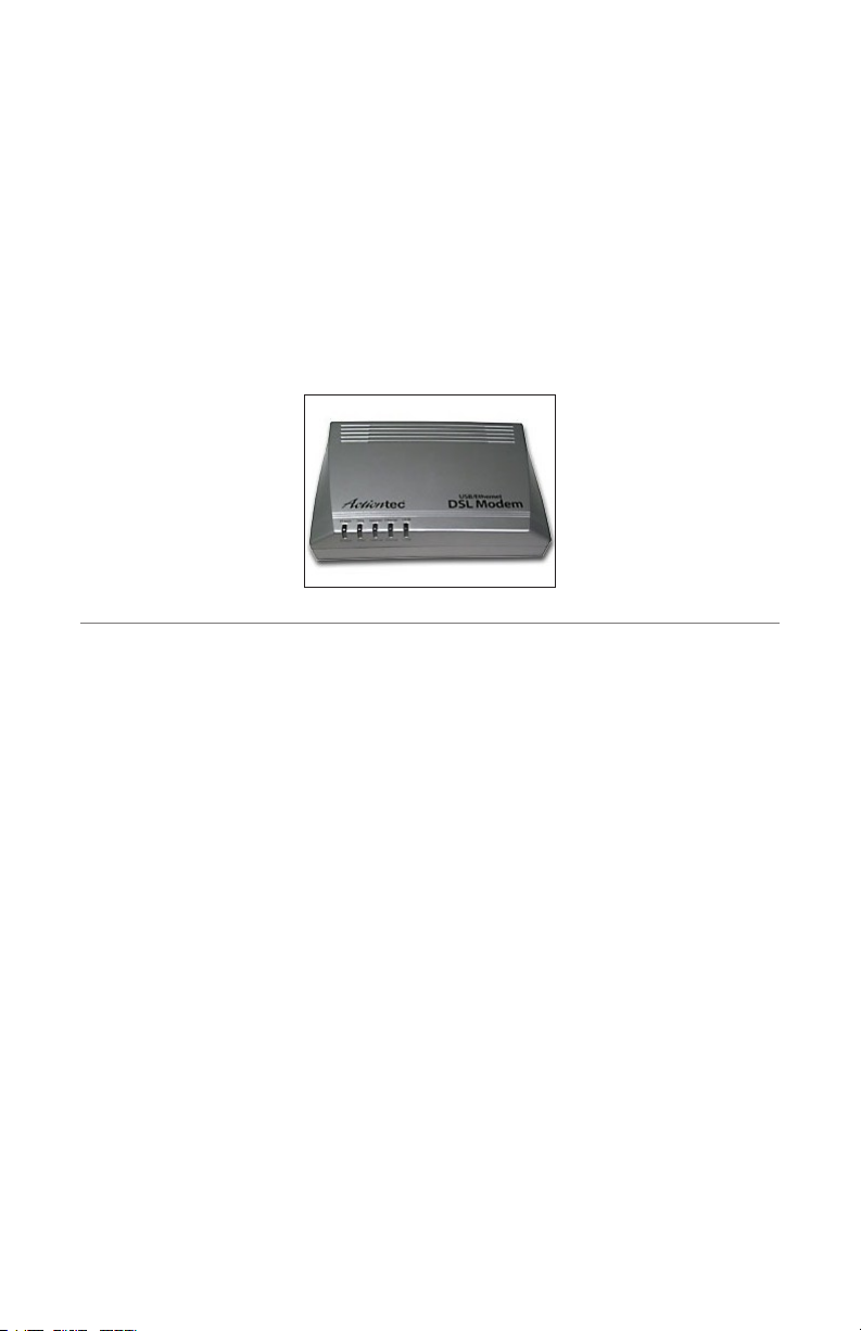
USB/Ethernet
DSL Modem
Model #: GT701
Firmware Version: 3.0.1.0.6.0-GT701
User Manual
Ver 1.0
Solutions for the Digital Life
™
Page 2

Table of Contents
1 Introduction 1
Package Contents 1
Minimum System Requirements 2
Features 2
Getting to Know the Modem 4
2 Setting Up the Modem 7
Connecting a Computer to the Modem 7
Installing Phone Filters 22
Setting Up the DSL Connection 26
3 Performing a Basic Setup 31
Basic Setup 31
Changing the Admin User Name and Password 33
4 Using Advanced Setup 35
Accessing Advanced Setup 35
WAN IP Address 36
LAN IP Address 40
DHCP Server 40
Services Blocking 42
Website Blocking 43
Remote Management 44
Application Layer Gateway and Port Forwarding 45
DMZ Hosting 46
Firewall 47
Dynamic Routing 49
NAT (Network Address Translation) 50
Static Routing 50
UPnP (Universal Plug and Play) 51
Time Zone 51
Remote Syslog Capture 52
5 Viewing the Modem’s Status 53
General Status 53
Routing Table 55
ARP Table 55
WAN Status 56
LAN Status 57
Active User List 57
i
Page 3

Actiontec USB/Ethernet DSL Modem User Manual
6 Using Utilities 59
Web Activity Log 59
System Log 60
DSL Settings 61
Restore Default Settings 62
Upgrade Firmware 62
7 Setting Up a Network 63
Ethernet 63
USB 68
8 Troubleshooting 73
Troubleshooting 73
Frequently Asked Questions 74
a Reference 79
Locating Computer Information 79
Locating Windows Operating System Files 80
b Setting Up Static IP on the Computer 83
Windows 98 SE 83
Windows Me 86
Windows 2000 89
Windows XP 93
c Computer Security 97
Comparing DSL Service with a Dial-Up Modem 97
Modem Security 98
Computer Security 98
Electronic Security 99
d Specifications 101
General 101
LED Indicators 102
Environmental 102
e Glossary 103
f Non-Windows System Setup 107
Classic 107
OS X 109
Notices 111
Regulatory Compliance Notices 111
Modifications 111
Miscellaneous Legal Notices 112
Limited Warranty 113
ii
ii
Page 4
Introduction
1
Thank you for purchasing the Actiontec USB/Ethernet DSL Modem. The Modem
is the simplest way to connect computers to a high-speed broadband connection.
This easy-to-use product is perfect for the home office or small business. If you
want to take your computing to the next level, the Actiontec USB/Ethernet DSL
Modem is sure to be one of the keys to your success.
Package Contents
s Actiontec USB/Ethernet DSL Modem
s Power cord
s Phone filters
s DSL cable
s Yellow (Ethernet) cable
s Blue (USB) cable
s Installation CD (includes user manual)
s Quick Start guide
s Start Here guide
s Technical Support card
1
Page 5

Actiontec USB/Ethernet DSL Modem User Manual
3
Chapter 1 Introduction
Minimum System Requirements
s Internet DSL service
s Compatible laptop, desktop, or Macintosh computer with an available
Ethernet or USB (USB compatible with PCs only)
s Microsoft Windows 98, 98 Second Edition (SE), Millennium Edition (Me), NT
4.0, 2000, XP; Mac OS 7.1 and above
Note: USB LAN port is not supported with Microsoft Windows
☞
95 and NT 4.0, or any Mac OS.
s Internet Explorer 4.0 or higher (5.x recommended) or Netscape Navigator
4.0 or higher (4.7 recommended)
s TCP/IP network protocol installed
Features
s Plug-and-Play installation support for systems with Windows operating
systems (98SE, Me, 2000, and XP)
s ADSL WAN port (RJ-11)
s Compliant with full-rate ANSI T1.413 Issue 2, ITU G.992.1 (G.dmt) and
G.992.2 (G.lite) standard
s Auto-handshake for different ADSL flavors
s USB 1.1 device specification compliance
s 12 Mbps USB data rate (full speed)
s Multiprotocol encapsulation over ATM, PPP over ATM, PPP over Ethernet
s Precise ATM traffic shaping
s IP packet routing and transparent bridge
s Routing protocol supports RIP-1, RIP-2, static routing
2
Page 6

Chapter 1 Introduction
s Built-in NAT, DHCP server
s DNS relay support
s PAP/CHAP authentication, administrative passwords through Telnet and
HTTP
s Compliant with IEEE 802.3 Ethernet standard
s 10/100 Base-T Ethernet port
s Flow control support for Fast Ethernet
s Web-based configuration setup
s Default configuration backup restore
s Firmware upgradeable
s Web download support
3
Page 7

Actiontec USB/Ethernet DSL Modem User Manual
5
Chapter 1 Introduction
Powe
r
DSL
Int
ern
e
t
Et
h
er
ne
t
US
B
Power
DSL
Int
erne
t
E
t
herne
t
U
S
B
USB/Ethern
et
DSL Mode
m
Getting to Know the Modem
This section contains a quick description of the Modem’s lights, ports, etc.
The Modem contains several indicator lights (LEDs) on its front panel and a series
of ports on its rear panel.
Front Panel
The front panel of the Modem features five lights: Power, DSL, Internet,
Ethernet, and USB.
Power Light
The Power light displays the Modem’s current status. If the Power light glows
steadily green, the Modem is receiving power and fully operational. When the
Power light flashes rapidly, the Modem is initializing. If the Power light is not
illuminated when the Power cord is plugged in and the Power switch is turned
on, the Modem has suffered a critical error and technical support should be
contacted.
DSL Light
The DSL light illuminates when the Modem is connected to a DSL line. When it
flashes, the Modem is training for your DSL service.
4
Page 8
Chapter 1 Introduction
Power
R
e
se
t
P
h
o
n
e
USB
E
t
h
er
n
e
t
Internet Light
When the Internet light glows steadily, the Modem is connected to the DSL provider.
Ethernet Light
The Ethernet light illuminates when the Modem is connected via its Ethernet
port.
USB Light
The USB light illuminates when the Modem is connected via its USB port.
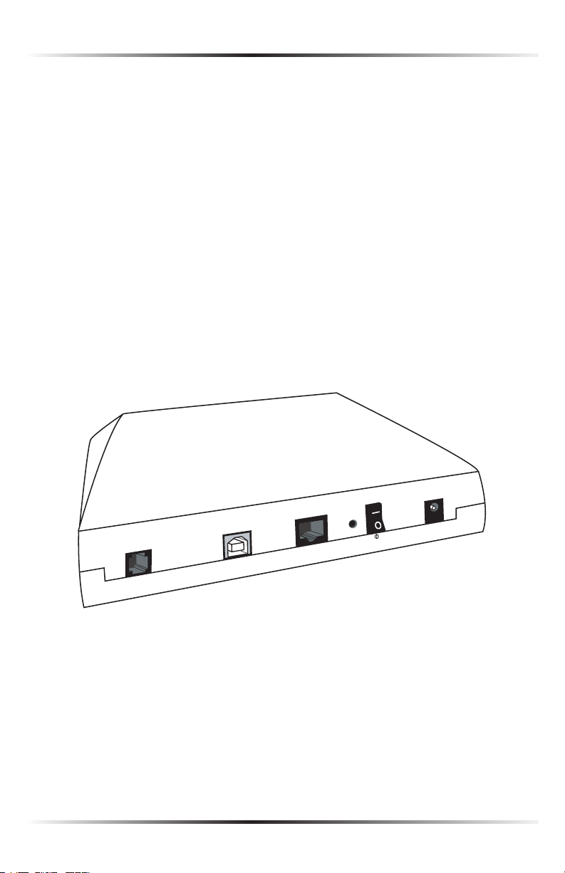
Rear Panel
The rear panel of the Modem contains four ports (Phone, USB, Ethernet, and
Power), as well as Reset and Power switches.
Phone Port
The Phone port is used to connect the Modem to a DSL (Digital Subscriber
Line) connection.
5
Page 9

Actiontec USB/Ethernet DSL Modem User Manual
USB Port
The USB port is used to connect a computer to the Modem via USB cable.
Note: It is not recommended to perform a recovery or update
☞
for the Modem from a computer connected via USB.
Ethernet Port
The Ethernet port is used to connect computers to the Modem via Ethernet
cable. The Ethernet port is a 10/100 Mbps auto-sensing port, and either a
straight-through or crossover Ethernet cable can be used when connecting to
the port.
Power Port
The Power port is used to connect the Power cord to the Modem.
Warning: Do not unplug the Power cord from the Modem dur-
N
ing the reset process. Doing so may result in permanent damage
to the Modem.
Reset Switch
Depressing the Reset switch for one or two seconds will power cycle the Modem
(similar to unplugging and then plugging in the Modem’s Power cord). To
restore the Modem’s factory default settings, depress and hold the Reset switch
for approximately 15 seconds. The reset process will start about 10 seconds after
releasing the switch.
Power Switch
The Power switch is used to power the Modem on and off.
Warning: Do not click the Power switch to its “off” postion
N
during the reset process. Doing so may result in permanent
damage to the Modem.
6
Page 10
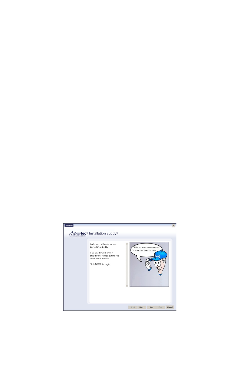
Setting Up the Modem
The instructions that follow parallel the steps contained in the Actiontec Installation
Buddy™, which provides a visual guide to setting up the Modem. It is recommended
the user run the Installation Buddy first, before attempting any other procedures.
To set up the Modem, it must be connected to a computer, and then configured.
After connecting this first computer, other computers can be added to the network
via USB or Ethernet (see “Setting Up a Network” on page 63).
Connecting a Computer to the Modem
Connecting a computer to the Modem for setup involves three basic steps: initial
setup, plugging in the Modem’s power cord, and connecting the Modem to the
computer.
Connecting Via Ethernet
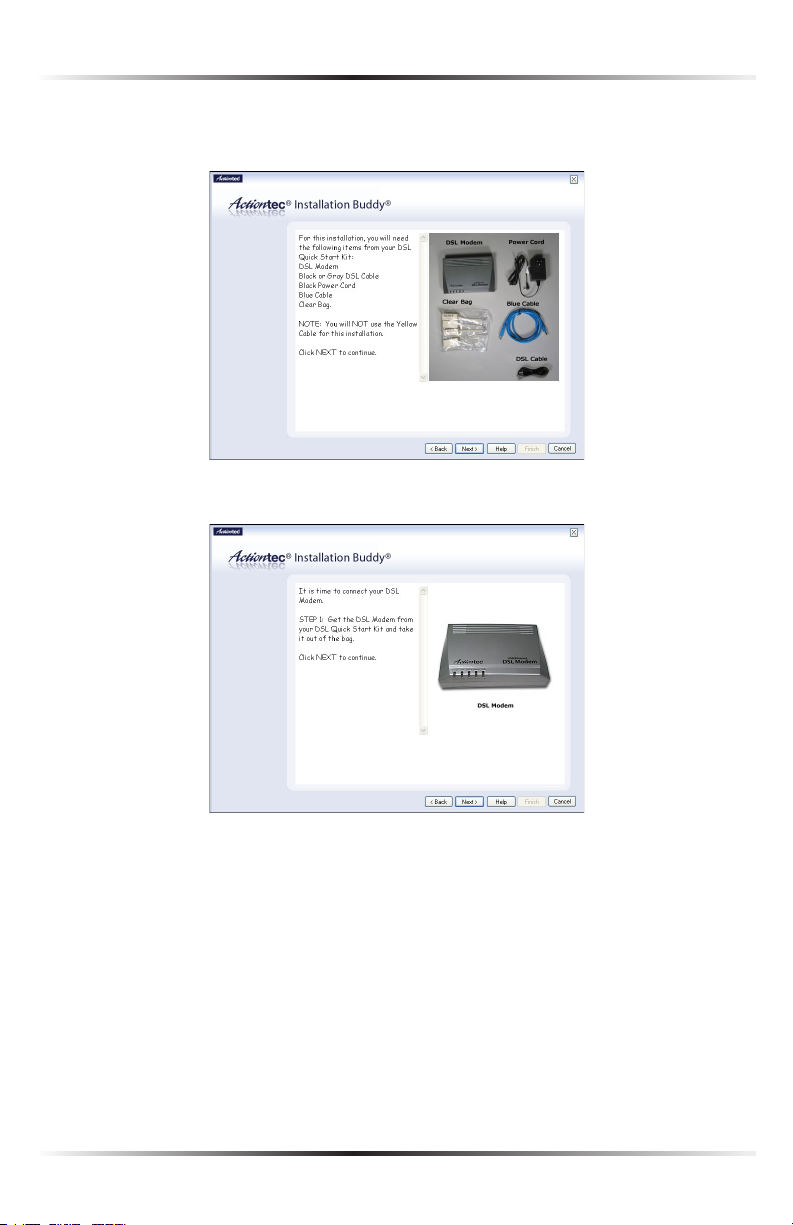
1. Insert the Installation CD in the CD-ROM drive of the computer. The
Installation Buddy starts automatically. Wait until the following screen
appears, read the on-screen instructions, then click Next.
2
7
Page 11
Actiontec USB/Ethernet DSL Modem User Manual
9
Chapter 2 Setting Up the Modem
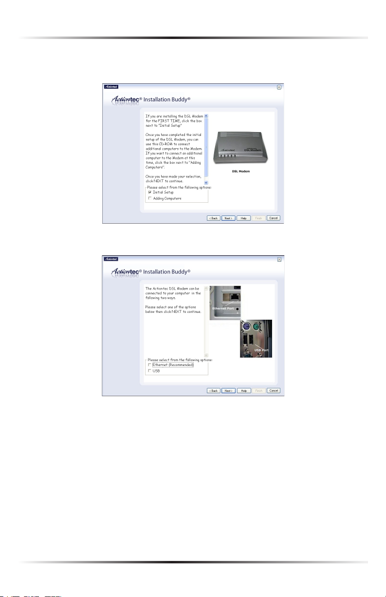
2. Read the instructions, select Initial Setup by clicking on the appropriate check
box, then click Next.
3. Click in the check box next to Ethernet (Recommended), then click Next.
8
Page 12
Chapter 2 Setting Up the Modem
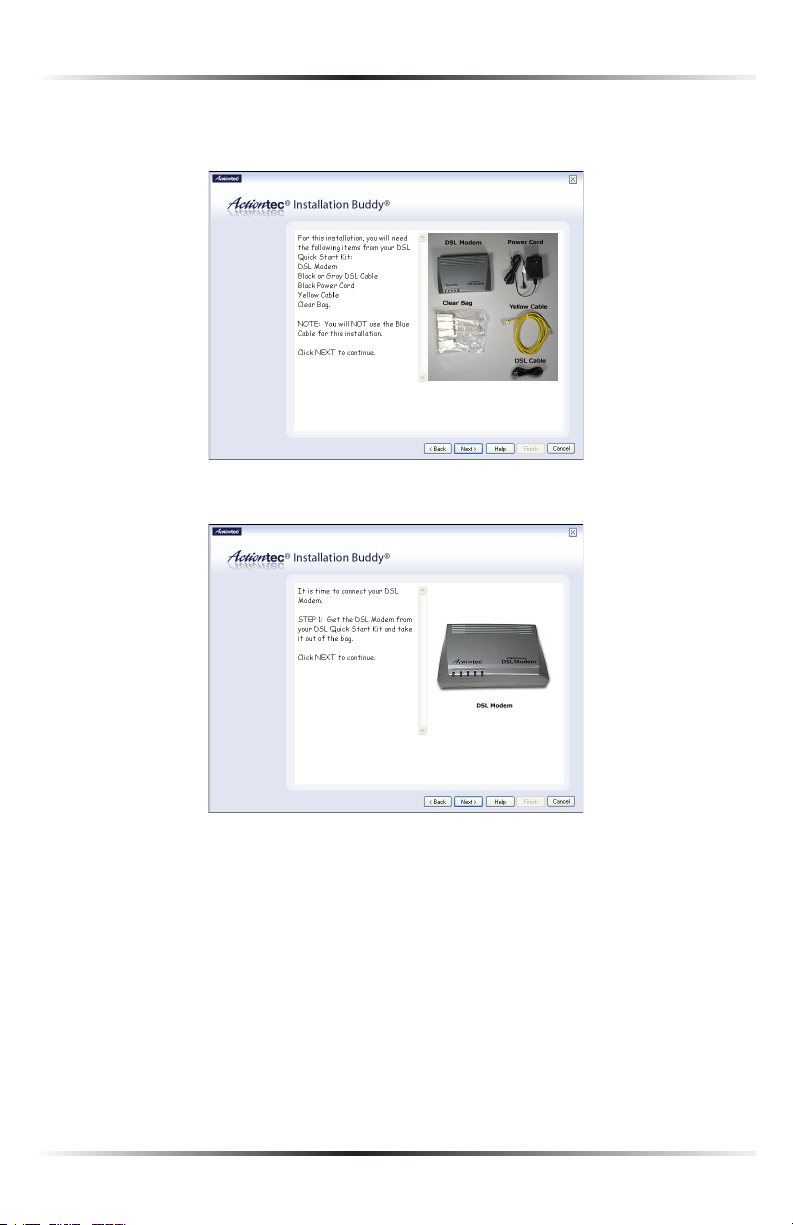
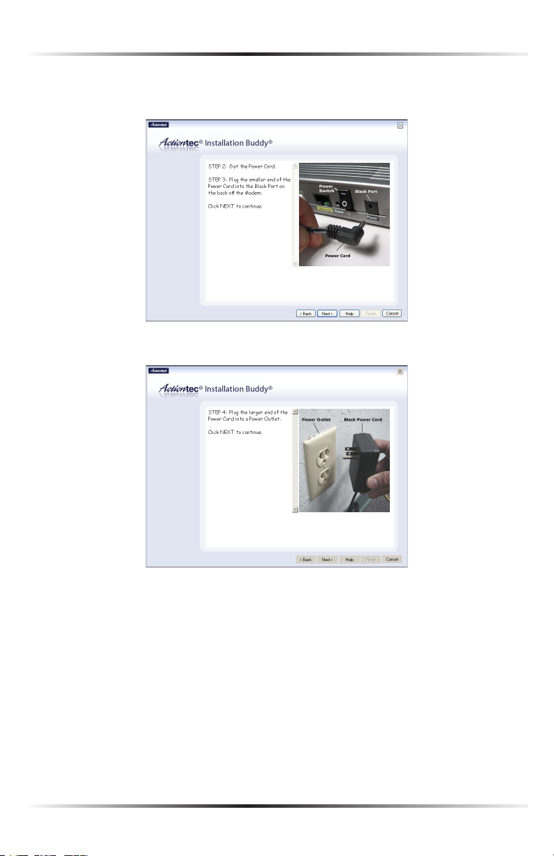
4. Make sure the items needed to connect the Modem to the first computer are
included in the kit, then click Next.
5. Get the Modem from the kit, then click Next.
9
Page 13

Actiontec USB/Ethernet DSL Modem User Manual
11
Chapter 2 Setting Up the Modem
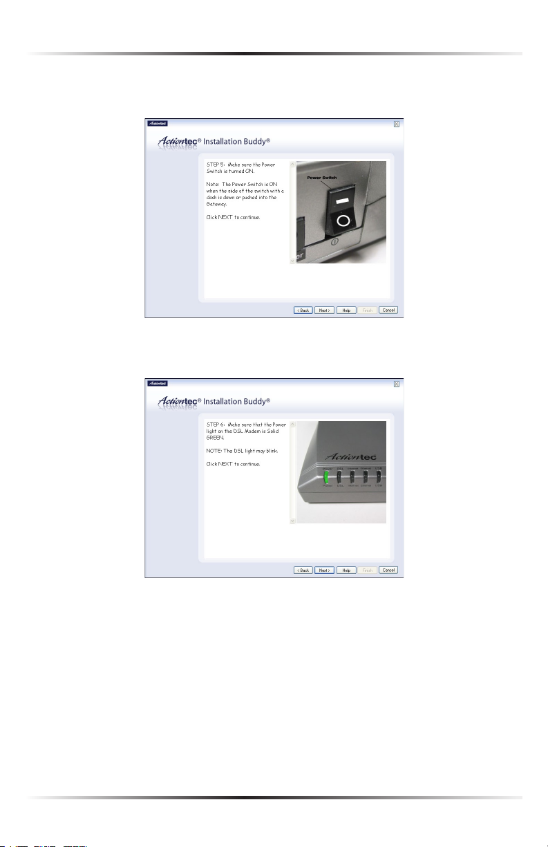
6. Get the Power cord and plug the smaller end into the black Power port on
the rear panel of the Modem, then click Next.
7. Plug the larger end of the Power cord into a power outlet, then click Next.
10
Page 14
Chapter 2 Setting Up the Modem
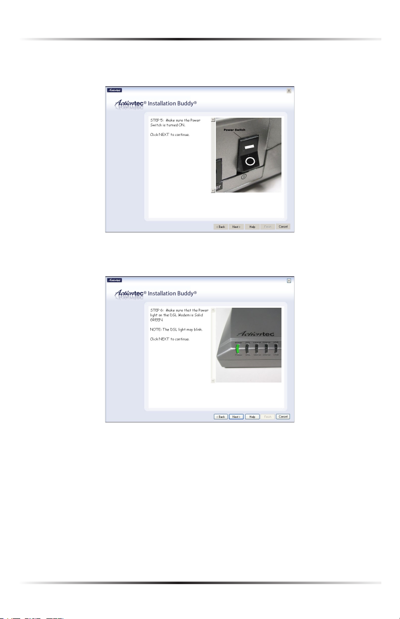
8. Click the On/Off switch to its on position (as shown in the picture on-
screen), then click Next.
9. Confirm the Power light on the front of the Modem glows solid green, then
click Next.
11
Page 15
Actiontec USB/Ethernet DSL Modem User Manual
13
Chapter 2 Setting Up the Modem
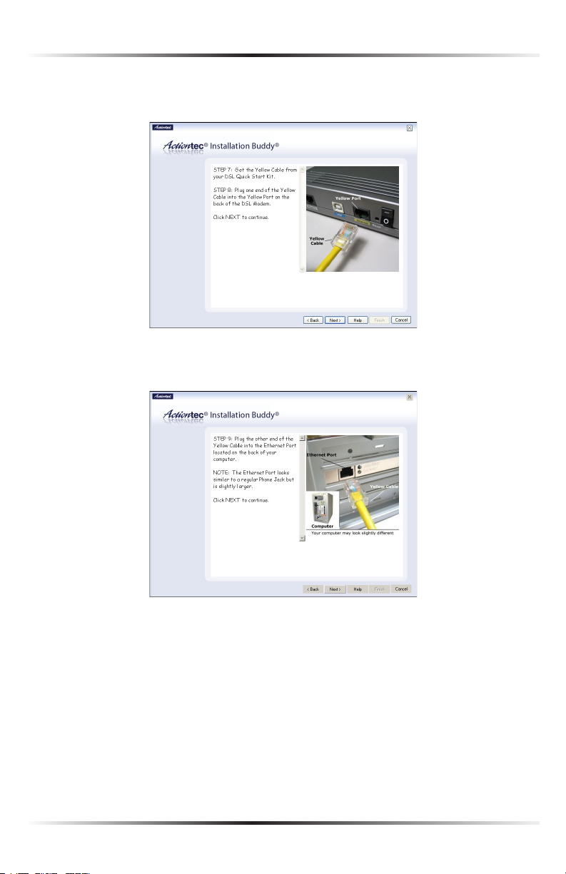
10. Get the yellow Ethernet cable from the kit and plug one end into the yellow
Ethernet port on the back of the Modem, then click Next.
11. Plug the other end of the yellow Ethernet cable into an Ethernet port on
the back of the computer. Click Next.
Note: An Ethernet port looks similar to a phone jack, but is
☞
slightly larger.
12
Page 16
Chapter 2 Setting Up the Modem
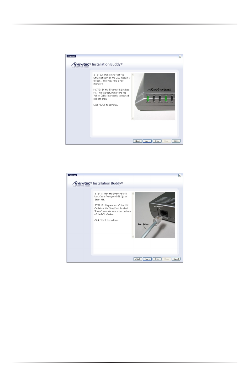
12. Make sure the Ethernet light on the front of the Modem glows solid green.
Click Next.
13. Get the black or gray DSL cable from the kit and plug one end into the gray
Line port on the rear panel of the Modem. Click Next.
13
Page 17
Actiontec USB/Ethernet DSL Modem User Manual
15
Chapter 2 Setting Up the Modem
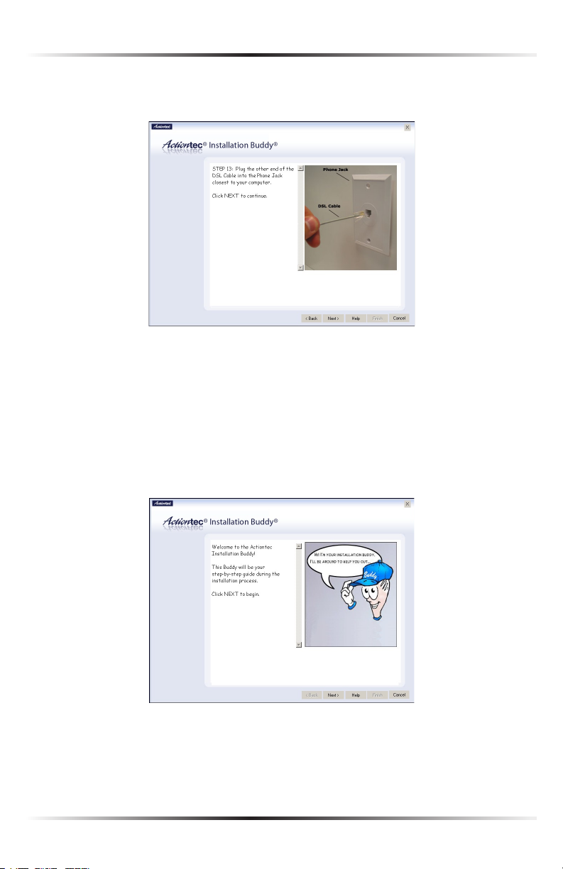
14. Plug the other end of the black or gray DSL cable into the phone jack clos-
est to the computer. Click Next.
The Modem is connected to a computer via Ethernet. Next, install the filters as
described in “Installing Filters” on page 22.
Connecting Via USB
1. Insert the Installation CD in the CD-ROM drive of the computer. The
Installation Buddy starts automatically. Wait until the following screen
appears, read the on-screen instructions, then click Next.
14
Page 18

Chapter 2 Setting Up the Modem
2. Read the instructions, select Initial Setup by clicking on the appropriate check
box, then click Next.
3. Click the check box next to USB, then click Next.
15
Page 19
Actiontec USB/Ethernet DSL Modem User Manual
17
Chapter 2 Setting Up the Modem
4. Make sure the items needed to connect the Modem to the first computer are
included in the kit, then click Next.
5. Get the Modem from the kit, then click Next.
16
Page 20
Chapter 2 Setting Up the Modem
6. Get the Power cord and plug the smaller end into the black Power port on
the rear panel of the Modem, then click Next.
7. Plug the larger end of the Power cord into a power outlet, then click Next.
17
Page 21
Actiontec USB/Ethernet DSL Modem User Manual
19
Chapter 2 Setting Up the Modem
8. Click the On/Off switch to its on position (as shown in the picture on-
screen), then click Next.
9. Confirm the Power light on the front of the Modem glows solid green, then
click Next.
18
Page 22
Chapter 2 Setting Up the Modem
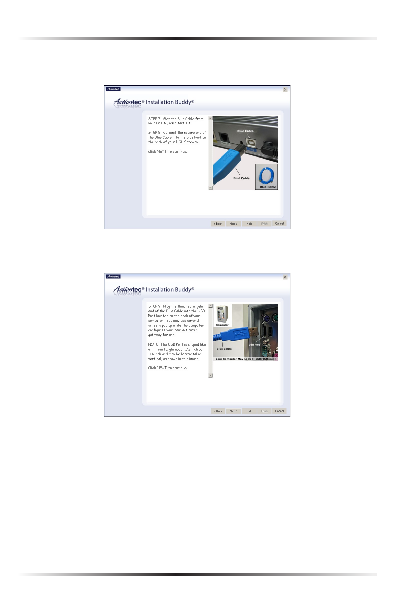
10. Get the blue USB cable from the kit and plug the square end into the blue USB
port on the back of the Modem, then click Next.
11. Plug the rectangular end of the blue USB cable into an USB port on the
front or back of the computer. Click Next.
19
Page 23
Actiontec USB/Ethernet DSL Modem User Manual
21
Chapter 2 Setting Up the Modem
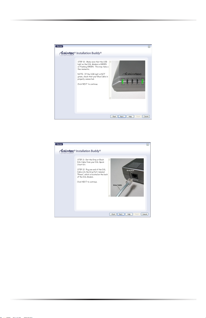
12. Make sure the USB light on the front of the Modem glows solid green. Click
Next.
13. Get the black or gray DSL cable from the kit and plug one end into the gray
Phone port on the rear panel of the Modem. Click Next.
20
Page 24
Chapter 2 Setting Up the Modem
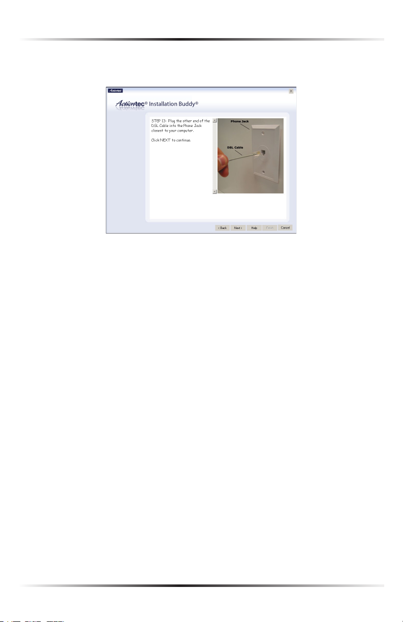
14. Plug the other end of the black or gray DSL cable into the phone jack clos-
est to the computer. Click Next.
The Modem is connected to a computer via USB. Next, install the filters as
described in “Installing Filters,” on the next page.
21
Page 25
Actiontec USB/Ethernet DSL Modem User Manual
23
Chapter 2 Setting Up the Modem
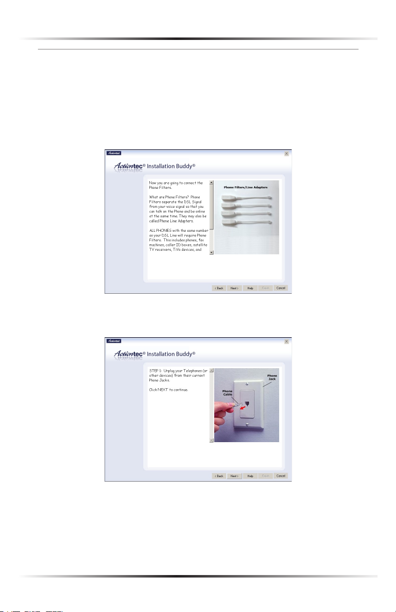
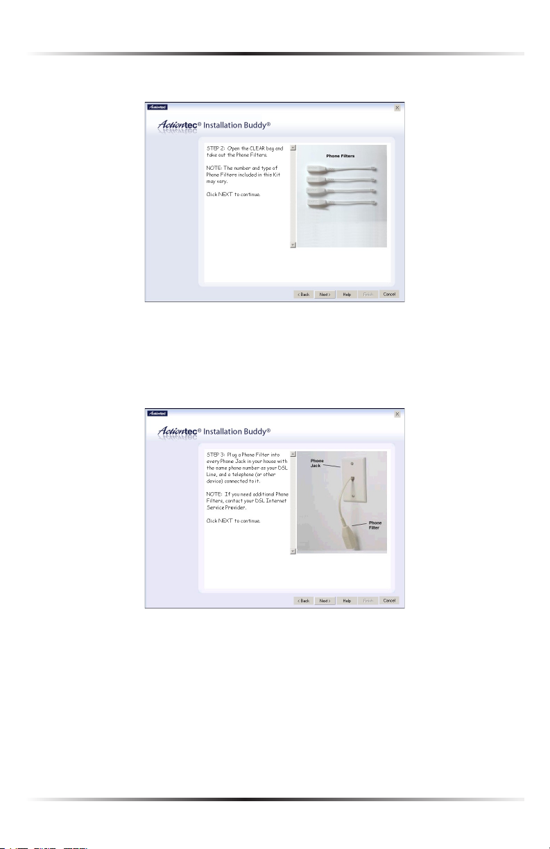
Installing Phone Filters
Phone filters allow the use of the telephone while online. All telephones and other
devices (answering machines, fax machines, etc.) using the same phone line (i.e.,
using the same phone number) as the DSL line must have a phone filter installed.
To install a phone filter:
1. Read the on-screen information, then click Next.
2. Read the on-screen information, then unplug all telephones and other devices from
their respective phone jacks. Click Next.
22
Page 26
Chapter 2 Setting Up the Modem
3. Get the phone filters. Click Next.
Caution: Do not unplug the black or gray DSL cable from the
M
phone jack near your computer.
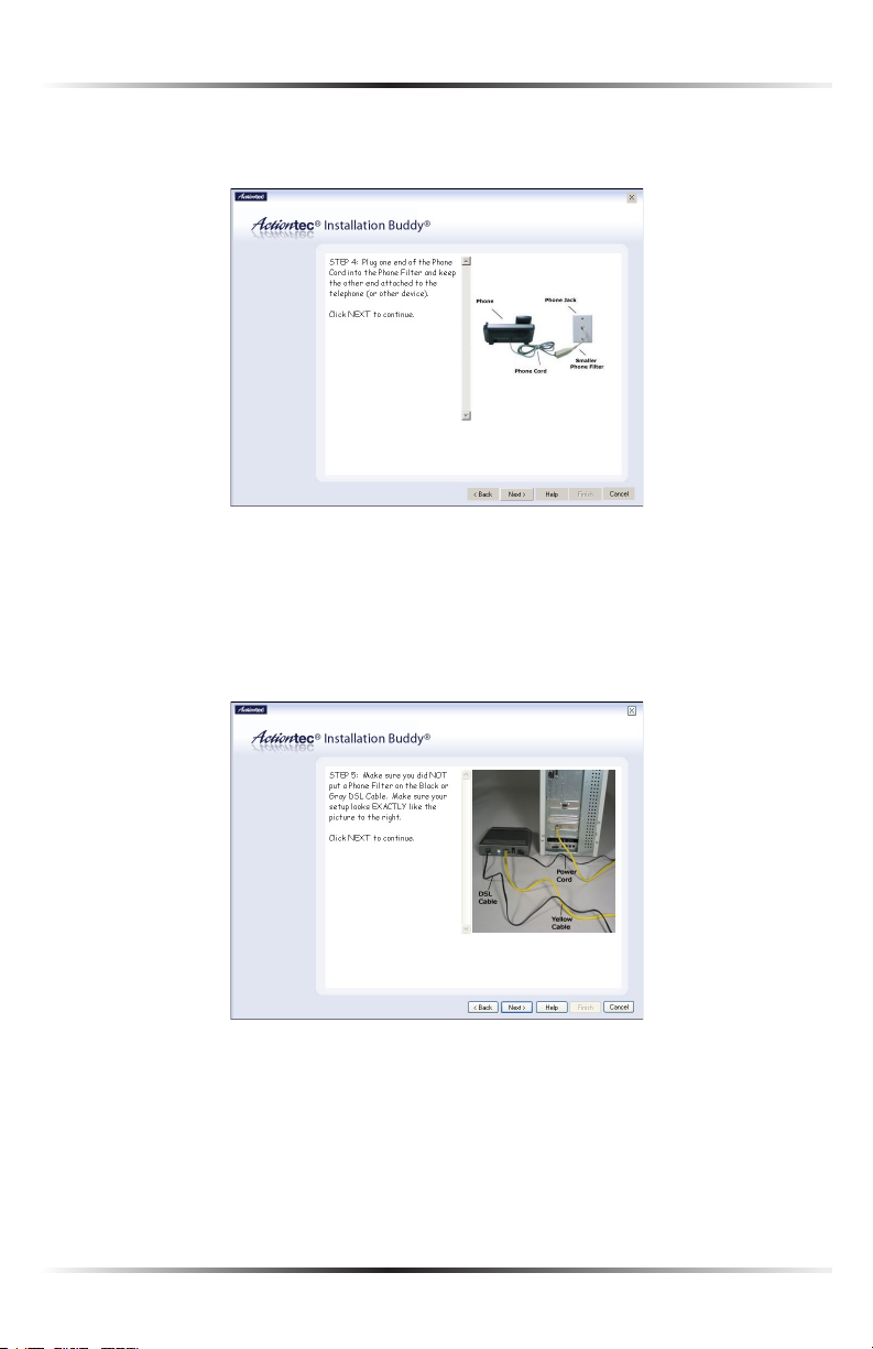
4. Plug a phone filter into every phone jack with a telephone or other device con-
nected to it, then click Next.
23
Page 27
Actiontec USB/Ethernet DSL Modem User Manual
25
Chapter 2 Setting Up the Modem
5. Plug the ends of the phone lines disconnected in step 2 into the phone filters
plugged into phone jacks. Click Next.
Caution: Do not plug a phone filter in the phone jack in which
M
the black or gray DSL cable is plugged.
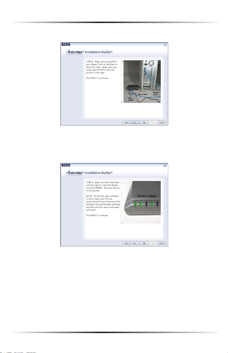
6. Read the on-screen instructions, and make sure the Modem is connected exactly as
shown, depending on whether the Modem is connected via Ethernet or USB.
Ethernet connection setup:
24
Page 28
Chapter 2 Setting Up the Modem
USB connection setup:
Click Next.
7. Make sure the DSL light on the Modem glows solid green (this may take a few
moments). Click Next.
Next, go to “Setting Up the DSL Connection” on the next page.
25
Page 29
Actiontec USB/Ethernet DSL Modem User Manual
27
Chapter 2 Setting Up the Modem
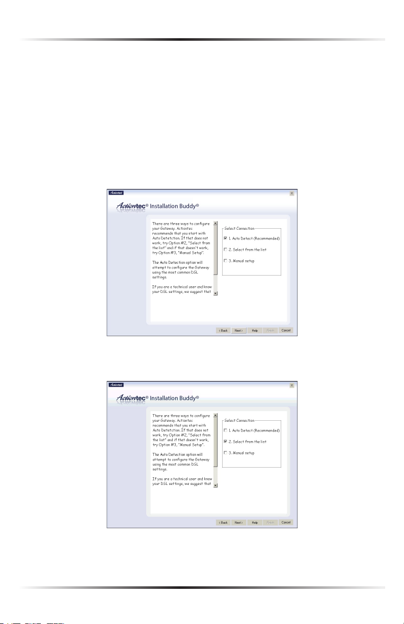
Setting Up the DSL Connection
After connecting the Modem and installing phone filters, the DSL connection must
be configured. To do this:
1. Select one of the options in the “Select Connection” box: Auto Detect, Select
from the list, or Manual Setup.
Auto Detect - if selected, click Next. The DSL connection is automatically
detected, and a series of informational screens will be displayed while the
Modem searches for the connection. If successful, go to step 2. If unsuccessful,
go to Select from the list, below.
Select from the list - If Auto Detect is not successful, or the user knows which
ISP to connect to, click in the “Select from the list” box, then click Next.
26
Page 30
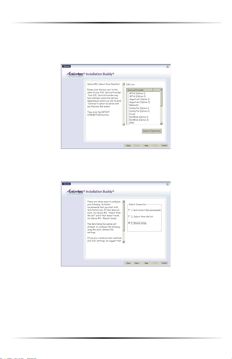
Chapter 2 Setting Up the Modem
In the next window, select the ISP being used from the list box on the right
(scroll down for more choices), then click Next. A series of informational
screens will display while the Modem searches for the connection. If the connection is successful, go to step 2. If not, go to “Manual Setup,” below.
Manual Setup - If the Auto Detect and Select from a list are not successful, or
the user knows how to configure VPI/VCI and Encapsulation settings, click in
the “Manual Setup” box, then click Next.
27
Page 31

Actiontec USB/Ethernet DSL Modem User Manual
29
Chapter 2 Setting Up the Modem
In the next window, enter the VPI/VCI and Encapsulation settings (the ISP
should provide these) then click Next.
2. Enter the user name and password in the appropriate text boxes (or click the
check box next to “My ISP does not require this information.”), then click Next.
28
Page 32

Chapter 2 Setting Up the Modem
3. Select the appropriate IP type. This information should be provided by the
ISP. When finished, click Next.
If Static IP is selected, go to step 4.
If Dynamic IP (DHCP) is selected, got to step 5.
4. In the next window, enter the IP Address, Subnet, Modem, DNS 1, and DNS
2 information (if applicable) in the proper text boxes. This information is
available in the Welcome Letter. When finished, click Next and go to step 6.
29
Page 33

Actiontec USB/Ethernet DSL Modem User Manual
5. The Installation Buddy checks the configuration of the Modem.
6. When the configuration is complete, a series of congratulations windows
appears. Read the on-screen information, then click through the next few
windows to exit the Installation Buddy.
The Modem is successfully configured and ready for use.
To make changes to the Modem’s Advanced Configuration settings, see Chapter 4,
“Using Advanced Setup.”
To create a network by connecting more computers to the Modem, see Chapter 7,
“Setting Up a Network.”
30
Page 34

Performing a Basic Setup
This chapter is a guide through a basic configuration setup of the Modem for users
who did NOT use the Actiontec Installation Buddy® to set up the Modem. The
basic setup includes instructions on how to connect the Modem to the ISP and
change the user name and password.
To complete a basic setup, the user will need information provided by the ISP and
access the Modem’s Web Configurator. This information from the ISP is sometimes
contained in a welcome letter or ISP worksheet. If this document is not available,
contact the ISP immediately and request one.
Basic Setup
Note: If you already set up the Modem using the Installation
☞
Buddy (as described in Chapter 2, “Setting Up the Modem”), the
settings described in this section have already been configured.
Please continue to chapter 4, “Using Advanced Setup,” to configure
the advanced settings of the Modem.
1. Open a Web browser. In the “Address” text box, type
http://192.168.0.1
then press Enter on the keyboard.
3
2. The Web Configurator’s “Main Menu” screen appears. Select Setup/
Configuration.
31
Page 35

Actiontec USB/Ethernet DSL Modem User Manual
33
Chapter 3 Performing a Basic Setup
3. Follow the instructions in the “Set Up/Configuration” screen, then click Begin
Basic Setup.
4. In the next screen, follow the on-screen instructions, then click Next.
5. In the next screen, select the type of connection provided by the ISP by
clicking in the circle next to PPPoA or PPPoE. If unsure about the selection,
check the information provided by the ISP. Then, enter the User Name and
Password provided by the ISP in the appropriate text boxes. If no user name
or password is needed, click in the box next to “My ISP does not require a
username and password.” Click Next.
32
Page 36

Chapter 3 Performing a Basic Setup
6. Click the Save and Restart button in the “Save and Restart” screen.
7. The “Congratulations” screen appears. The Modem is successfully configured.
The Power light flashes rapidly while the Modem restarts, then glows steadily
green when fully operational. The Internet light will also glow steadily green. The
Modem is now configured and users can start surfing the Web.
If an error stating the Web browser was unable to connect to the Internet appears,
check the configuration settings. Ensure all the information required by the ISP was
entered correctly.
Changing the Admin User Name and Password
To create or change the admin user name and password, controlling access to the
Modem’s Web Configurator screens, follow these instructions:
1. From the Setup/Configuration screen, select Admin Username/Password
from the menu on the left side.
33
Page 37

Actiontec USB/Ethernet DSL Modem User Manual
2. The “Change Admin Username/Password” screen appears. Enter a new
user name (optional) in the “New Username” text box, then a password in
the “New Password” text box. Re-enter the password in the “Re-enter New
Password” text box. Make sure to write the user name and password down
and keep them in a secure location. They will be needed to access to the
Modem’s Web Configurations screens in the future.
3. Click Save and Restart at the bottom of the screen.
4. The “Save and Restart” page appears. Click the Save and Restart button to
save the settings changed in the Change Admin Username/Password screen.
Once the Modem has rebooted, the password is active. To access the Modem’s Web
Configuration screens, the username and password must be entered.
34
Page 38

Using Advanced Setup
This section contains information concerning setting up the advanced features of
the Modem, such as wireless settings, remote management, and Web site blocking,
using the Modem’s Web Configurator.
Accessing Advanced Setup
To access the Web Configurator’s Advanced Setup screens:
1. Open a Web browser. In the “Address” text box type:
http://192.168.0.1
then press Enter on the keyboard.
2. The “Main Menu” screen appears. Select Setup/Configuration.
#
4
3. In the “Set Up/Configuration” screen, read the instructions, then select
Advanced Setup from the menu on the left side.
35
Page 39

Actiontec USB/Ethernet DSL Modem User Manual
37
Chapter 4 Using Advanced Setup
4. In the next screen, read the recommendations. To perform an advanced setup
on the Modem, click Begin Advanced Setup.
5. The “Configuring the Advanced Settings” screen appears. To check all the set-
tings, or if unsure of which settings to modify, select Next. To modify a specific configuration, click on its name in the menu bar on the left.
Note: To save changes made in any of the Advanced Setup
☞
screens, click Save and Restart at the bottom of the gray menu
on the left side of the screen.
WAN IP Address
Selecting WAN IP Address in the “Configuring the Advanced Settings” screen gen-
erates the “WAN IP Address” screen. WAN IP Address allows manual set up of the
IP address of the Modem. There are five ways to do this: Transparent Bridging,
Obtain an IP Address through PPPoE, Obtain an IP Address Through PPPoA,
Obtain an IP Address through DHCP, and Specify a Static IP Address.
Note: If unsure about which connection is present, check with
☞
the Internet Service Provider (ISP) before continuing.
36
Page 40

Chapter 4 Using Advanced Setup
After selecting a connection type, click Next to continue configuring the connection.
Transparent Bridging
Select this option to use the Modem as a transparent bridge. This option should
only be used if the Modem is being used as a modem to connect your computer to
the Internet via a DSL connection. When the Modem is being used as a transparent
bridge, it does not provide any firewall security.
Obtain an IP Address through PPPoE or PPPoA
Select one of these options to allow the Modem to use the Point-to-Point over
Ethernet (PPPoE) or Point-to-Point over ATM (PPPoA) protocol.
“Broadband Connection via PPPoE” screen:
37
Page 41

Actiontec USB/Ethernet DSL Modem User Manual
39
Chapter 4 Using Advanced Setup
“Broadband Connection via PPPoA” screen:
If a User Name and Password was entered in the Installation Buddy or during
Basic Setup, it should be displayed in the “Broadband Connection via PPPoE/
PPPoA” screen. If not, enter the information now. If the information is unavailable,
contact the ISP.
PPP Auto Connect
If PPP auto connect is activated (by clicking in the appropriate check box), the
Modem will attempt to automatically redial the PPP connection if it is dropped
or disconnected during an online session. Actiontec recommends that you turn
PPP Auto Connect ON.
Encapsulation (PPPoA only)
Select one of the encapsulation options, based on information received from the
ISP.
Obtain an IP Through DHCP
Select this option if the IP service is configured to use RFC 1483 Bridged or Routed
(used for configurations without a Static IP assigned by an ISP). In this mode, the
Modem will query the Internet Service Provider (ISP) to receive the IP address and
routing information, which will terminate at the Modem, as opposed to the IP
address and routing information being bridged to terminate at the computer. This
allows the use of the router capabilities for the Local Area Network (LAN).
Some ISPs need to authenticate their end users with a Host Name and/or Domain
Name. If this is the case, check with the ISP for a host name and domain name and
enter them in the appropriate text boxes in the “Broadband Connection via DHCP”
screen. If the ISP does not require these settings, leave the text boxes blank.
38
Page 42

Chapter 4 Using Advanced Setup
Note: Contact the ISP if unsure of the proper configuration.
☞
Specify a Static IP Address
Select this option if the ISP service is configured to use RFC 1483 Bridged or
Routed using a Static IP Address. Enter the IP Address, Subnet Mask, and Default
Gateway Address provided by the ISP in the “Broadband Connection via Static
IP Address” screen, which causes the IP address and routing information to termi-
nate at the Modem, as opposed to the IP address and routing information being
bridged to terminate at the computer. This allows the use of the router capabilities
for the Local Area Network (LAN).
Note: Contact the ISP if unsure of the proper configuration.
☞
39
Page 43

Actiontec USB/Ethernet DSL Modem User Manual
41
Chapter 4 Using Advanced Setup
LAN IP Address
Selecting LAN IP Address in the “Configuring the Advanced Settings” screen generates the “LAN IP Address” screen.
The values in the “Device IP Address” and “Device LAN Netmask” text boxes are the
IP address and Subnet mask of the Modem as seen on the network. These values
can be modified for your LAN network, but Actiontec recommends keeping the
default factory settings (IP address 192.168.0.1 Subnet mask 255.255.255.0).
Note: If the Modem’s LAN IP Address is modified, ensure the
☞
DHCP Server range is within the same subnet. For more infor-
mation, see “DHCP Server Configuration.”
After changing settings, click Next or Back to continue, or Save and Restart to
make all changes permanent.
DHCP Server
Selecting DHCP Server in the “Configuring the Advanced Settings” screen generates the “DHCP Server” screen. The Modem has a built-in DHCP (Dynamic Host
Configuration Protocol) server that automatically assigns a different IP address to
each computer on the network, eliminating IP address conflicts.
The factory default setting is On. To disable the DHCP Server, select Off.
40
Page 44

Chapter 4 Using Advanced Setup
Actiontec strongly recommends leaving the DHCP Server option On. If the DHCP
Server option is Off, ensure the IP addresses of the networked computers are
on the same subnet as the IP address of the Modem. For more information, see
“DHCP Server Configuration.”
DHCP Server Configuration
Clicking Next in the “DHCP Server” screen (if the DHCP server is activated) generates
the “DHCP Server Configuration” screen. Change IP address range and DNS server
information here.
Beginning IP Address
The “Beginning IP Address” is the IP address at which the DHCP server starts
assigning IP addresses. Actiontec recommends keeping the factory default setting
(192.168.0.2).
Ending IP Address
The “Ending IP Address” is the IP Address at which the DHCP Server stops
assigning IP addresses. Actiontec recommends keeping the factory default set-
tings (192.168.0.254).
The beginning and ending IP addresses define the IP address range of the
Modem. If the default values are left intact, the Modem supplies a unique IP
address between 192.168.0.2 and 192.168.0.254 to each computer on the network. Note that the first three groups of numbers of the addresses are identical;
this means they are on the same subnet. The IP address of the Modem must
be on the same subnet as the IP address range it generates. For instance, if the
Modem’s IP address is changed to 10.33.222.1, set the beginning IP address to
10.33.222.2, and the ending IP address to 10.33.222.254.
41
Page 45

Actiontec USB/Ethernet DSL Modem User Manual
43
Chapter 4 Using Advanced Setup
Lease Time
“Lease Time” is the amount of time, in seconds, the DHCP server will lease a
particular IP address. Default is 86400 seconds (24 hours), after which a new IP
address must be released. To extend the lease time, enter a larger number.
Domain Name
“Domain Name” allows a network administrator to enter a domain name if the
network is being used in a domain environment.
DNS (Dynamic or Static)
These options designate the type of DNS server provided by the ISP. If the ISP
provided DNS server information, select the type here. If not, leave as is.
DNS Server 1
“DNS Server 1” is the primary DNS server provided by the ISP. If the ISP provided DNS server information, enter it here. If not, leave the text box intact.
DNS Server 2
“DNS Server 2” is the secondary DNS provided by the ISP. If the ISP provided
secondary DNS server information, enter it here. If not, leave the text box intact.
Services Blocking
Selecting Services Blocking in the “Advanced Configuration” screen generates the
“Services Blocking” screen.
42
Page 46

Chapter 4 Using Advanced Setup
To modify Internet privileges (Web, FTP, Newsgroups, etc.) for the computers on
the network:
1. Enter the computer’s IP address in the IP Address: text box.
2. Select the Internet service(s) to be blocked.
3. Click Add to enter the computer’s IP address in the “Blocked IP Address List”
text box.
4. To remove blocked services, select the computer’s IP address in the “Blocked
IP Address List” text box and click Remove.
Website Blocking
Selecting Website Blocking in the “Configuring the Advanced Settings” screen
generates the “Website Blocking” screen. This feature enables the Modem to block
Web sites to all computers on the network. To block a Web site, enter the address
of the Web site in the “Website” text box and click Add. The blocked Web site
address is displayed in the “Blocked Website List” text box, and will not be available to computers on the network. To remove a blocked Web site, click on it in the
“Blocked Website List,” then click Remove. Website Blocking supports blocking up
to 50 Web sites.
43
Page 47

Actiontec USB/Ethernet DSL Modem User Manual
45
Chapter 4 Using Advanced Setup
Remote Management
Selecting Remote Management in the “Configuring the Advanced Settings” screen
generates the “Remote Management” screen. Remote Management allows access
to the Modem through the Internet via another computer. Actiontec recommends
leaving the Remote Management Off (the factory default setting).
To access the Modem from the Internet, activate Remote Management by selecting
On and writing down the WAN IP address of the Modem (see “WAN IP Address”).
On a computer outside of the network, open a Web browser and enter the Modem’s
WAN IP address in the address text box. A username and password prompt appears
in the browser window. Enter your username and password to access the Modem.
Note: Before Remote Management can be activated, the admin-
☞
istrator password must be set. To do this, go to the Setup screen
and select Change Admin Password. Follow the instructions in
the subsequent screens.
44
Page 48

Chapter 4 Using Advanced Setup
Application Layer Gateway and Port Forwarding
Selecting Application Layer Gateway in the “Configuring the Advanced Settings”
screen generates the “Application-Level Gateway (ALG) and Port Forwarding”
screen. Port forwarding allows certain programs to bypass the Modem’s built-in
firewall, allowing access to parts of the network (for hosting a Web or ftp server,
for example). To use, select the host name of a computer on the network from the
“LAN Device” drop-down list (click the down arrow), then click Add. Next, select
a “Category” by clicking the appropriate radio button. In the “Available Rules” list
box, select a game, application, server, etc., then click Add>>. The selected item
appears in the “Applied Rules” list box. Repeat for each item needed
To remove an item from the Applied Rules list, highlight it, then click Remove.
To view an item’s rules (forwarded ports, etc.), highlight it, then click View Rule.
To create a custom set of rules, click the “User” radio button, then click New. The
“Rule Management” screen appears.
45
Page 49

Actiontec USB/Ethernet DSL Modem User Manual
47
Chapter 4 Using Advanced Setup
In this screen, the user can create a custom set of rules for a game or application not listed in the Application Level Gateway screen. Enter the “Rule Name,”
“Protocol,” “Port Start,” “Port End,” and “Port Map” in the appropriate text boxes,
then click Apply. The rules are summarized at the bottom of the screen, and the
rule set will appear in the Application Level Gateway screen after clicking Back.
DMZ Hosting
Selecting DMZ Hosting in the “Configuring the Advanced Settings” screen generates the “DMZ Hosting” screen. To use DMZ hosting, enter the IP address of the
computer on the network to be used as a DMZ host in the “DMZ Host IP Address”
text box, then click On.
DMZ hosting is used to support online gaming and Internet conferencing services.
These programs usually require multiple open ports, making the network accessible from the Internet. DMZ hosting symbolically places the DMZ host computer
outside of the Modem’s network. Actiontec recommends activating DMZ hosting
only as long as necessary.
Warning: The DMZ Host computer will be vulnerable to com-
M
puter hackers on the Internet while in DMZ mode.
46
Page 50

Chapter 4 Using Advanced Setup
Firewall
Selecting Firewall in the “Configuring the Advanced Settings” screen generates the
“Firewall Security Level” screen. Select the level of security needed for the network.
High
If High is selected in the “Firewall Security Level” screen, the services listed at the
bottom of the screen (HTTP, FTP, POP3, SMTP, IMAP, IMAPv3, DNS, IPSEC IKE,
IPSEC ESP, HTTPS, and NNTP) are the only ones allowed to pass through the fire-
wall. All other services will be blocked.
47
Page 51

Actiontec USB/Ethernet DSL Modem User Manual
49
Chapter 4 Using Advanced Setup
Medium
If Medium is selected in the “Firewall Security Level” screen, the services listed
at the bottom of the screen (HTTP, FTP, POP3, SMTP, IMAP, IMAPv3, DNS, IPSEC
IKE, IPSEC ESP, HTTPS, and NNTP) are allowed to pass through the firewall.
Additionally, the user can click in the appropriate check box to allow or deny
access for a particular service (check mark in the check box to allow; blank check
box to deny). All services not listed are denied access.
Low
If Low is selected in the “Firewall Security Level” screen, the services listed at
the bottom of the screen (NETBIOS-SSN, DNS, EPMAP, PROFILE, NETBIOS-NS,
NETBIOS-DGM, MICROSOFT-DS, SNMP, LDAP, and MICROSOFT-GC,) are blocked-
by the firewall. Additionally, the user can click in the appropriate check box to
allow or deny access for a particular service (check mark in the check box to allow;
blank check box to deny). All services not listed are denied access.
48
Page 52

Chapter 4 Using Advanced Setup
Off
If Off is selected in the “Firewall Security Level” screen, firewall filtering is based
solely on the basic NAT firewall.
Dynamic Routing
Selecting Dynamic Routing in the “Configuring the Advanced Settings” screen
generates the “Dynamic Routing” screen.
If another router or gateway is set up behind the Modem in the network configuration, consult the documentation that came with the other router/gateway to see
what kind of Dynamic Routing is required operate it with the Modem, then select
the appropriate option.
49
Page 53

Actiontec USB/Ethernet DSL Modem User Manual
51
Chapter 4 Using Advanced Setup
NAT (Network Address Translation)
Selecting NAT in the “Configuring the Advanced Settings” screen generates the
“NAT” screen. The Modem’s basic firewall security is based on NAT. Disabling NAT
allows the computers connected to the Modem to be accessed by outside parties.
Do not turn NAT off unless instructed to do so by the ISP.
Static Routing
Selecting Static Routing in the “Configuring the Advanced Settings” screen generates the “Static Routing” screen. Enter the addresses in their respective text boxes,
then click Add. The address will appear in the “Static Routing Table.” To remove
an address, highlight it by clicking on it in the Static Routing Table, then click
Remove.
50
Page 54

Chapter 4 Using Advanced Setup
UPnP (Universal Plug and Play)
Selecting UPnP in the “Configuring the Advanced Settings” screen generates the
“UPnP” screen. In this screen, the Universal Plug and play option is turned on or
off by activating the appropriate circle.
Universal Plug and Play is a zero-configuration networking protocol that allows
hardware and software (such as Netmeeting) to operate more efficiently. If
Netmeeting is not running properly, activate UPnP.
Note: Activating UPnP presents a slight security risk. After fin-
☞
ishing with the hardware or software using UPnP, Actiontec rec-
ommends deactivating UPnP.
Time Zone
Selecting Time Zone in the “Configuring the Advanced Settings” screen generates
the “Time Zone” screen. In this screen, select the time zone in which the Modem is
being used.
51
Page 55

Actiontec USB/Ethernet DSL Modem User Manual
Remote Syslog Capture
Selecting Remote Syslog Capture in the “Configuring the Advanced Settings”
screen generates the “Remote Syslog Campter” screen. In this screen, the user can
configure the Modem to allow a remote computer to access the Modem’s system
logs.
52
Page 56

Viewing the Modem’s Status
After configuring the Modem, settings can be viewed by selecting Status in the
Web Configurator’s Main Menu. In the menu on the left side, there are other
Status options available: Routing Table, ARP Table, WAN Status, LAN Status,
and Active User List.
No settings (other than connecting or disconnecting from the Internet) can be
changed from the Current Status screen.
General Status
After configuring the Modem, settings can be viewed by selecting Status in the
Main Menu. The “General Status” screen appears, displaying many of the Modem’s
settings. No settings (other than connecting or disconnecting from the Internet
by clicking on Connect or Disconnect) can be changed from the General Status
screen.
5
Firmware Version
Displays the firmware version the Modem is currently running.
MAC Address
Displays the MAC (Media Access Control) address of the Modem.
53
Page 57

Actiontec USB/Ethernet DSL Modem User Manual
55
Chapter 5 Viewing the Modem’s Status
WAN - Connection
Displays the state of the connection to the ISP service (Connected, Disconnected,
or Connecting).
WAN - Mode
Displays the type of connection used to communicate with the ISP.
WAN - IP Address
Displays the IP address the ISP assigned to the Modem.
WAN - Subnet Mask
Displays the subnet mask address the ISP assigned to the Modem.
WAN - Gateway
Displays the Gateway address (for the IP address and subnet mask) the ISP
assigned to the Modem.
WAN - DNS #1 & #2
Displays the Domain Name Server address(es) the ISP assigned to the Modem.
LAN - IP Address
Displays the Local Area Network’s (LAN) IP address.
LAN - Net Mask
Displays the subnet mask address configured for the LAN IP address.
LAN - DHCP Server
Displays the state of the DHCP Server (On or Off).
54
Page 58

Chapter 5 Viewing the Modem’s Status
In the menu on the left side, there are other Status options available: Routing
Table, ARP Table, WAN Status, LAN Status, and Active User List. Click to gen-
erate the Status option of choice.
Routing Table
Selecting Routing Table generates the “Routing Table” screen. This screen displays
an overview of the Modem’s routes.
ARP Table
Selecting ARP Table generates the “ARP Table” screen. This screen displays the
Modem’s IP address, MAC address and interface type.
55
Page 59

Actiontec USB/Ethernet DSL Modem User Manual
57
Chapter 5 Viewing the Modem’s Status
WAN Status
Selecting WAN Status generates the “WAN Status” screen. This screen displays on
overview of the Modem’s WAN (Wide Area Network) connection, including infor-
mation concerning the WAN and DSL connection, as well as OAM statistics.
56
Page 60

Chapter 5 Viewing the Modem’s Status
LAN Status
Selecting LAN Status generates the “LAN Status” screen. This screen displays on
overview of the Modem’s LAN (Local Area Network) port connections, including
information concerning any Ethernet and USB connections.
Active User List
Selecting Active User List generates the “Active User List” screen. This screen dis-
plays a list of the users currently connected to the Modem accessing the Internet
with Network Address Translation (NAT) security activated.
57
Page 61

Actiontec USB/Ethernet DSL Modem User Manual
This page left intentionally blank.
58
Page 62

Using Utilities
6
To access the Modem’s Web-based Utilities, select Utilities from the Web
Configurator’s Main Menu screen. The “Utilities” screen appears.
From this screen, the Web activity and system log can be viewed, the DSL settings
changed, the Modem’s factory default settings restored, and the Modem’s firmware
upgraded.
Web Activity Log
The Web Activity Log provides information about the Web sites each computer
on the Modem’s network has visited. To access the Web Activity Log, select Web
Activity Log from the “Utilities” screen.
59
Page 63

Actiontec USB/Ethernet DSL Modem User Manual
61
Chapter 6 Using Utilities
Auto Refresh
To set the Web Activity Log screen to automatically refresh at certain intervals, activate the circle next to “Auto Refresh Every” at the bottom of the Web Activity Log
screen, then enter a time value (in seconds) in the text box, or click on the down
arrow and select a time value from the menu that appears. The Web Activity Log
will refresh at the selected interval.
Manual Refresh
To set the Web Activity Log screen to manually refresh, activate the circle next to
“Manual Refresh” at the bottom of the Web Activity Log screen. To refresh the Web
Activity Log screen, click Refresh.
System Log
The System Log provides information about the Modem’s activity. To access the
Web Activity Log, select Web Activity Log from the “Utilities” screen.
System Log (Size)
Select the size of the system log displayed here. The smaller the size, the shorter the
length of the system log saved.
60
Page 64

Chapter 6 Using Utilities
Display
View other saved logs by selecting a log from this drop-down list.
Save & Restart
Pressing this button saves any changes to the System Log screen and causes the
Save and Restart screen to appear.
Save Log As
Pressing this button allows the user to save a log as a file.
DSL Settings
To access DSL Settings, select DSL Settings from the “Utilities” screen. The
Modem’s VPI, VCI, Mode, and QoS (Quality of Service) settings can be changed
from this screen. Actiontec recommends not changing these values without first
consulting the ISP.
61
Page 65

Actiontec USB/Ethernet DSL Modem User Manual
Restore Default Settings
To restore the Modem to its factory default settings, select Restore Default Settings
from the “Utilities” screen. When the “Restore Default Settings” screen appears, click
Restore Default Settings. Any changes made to the Modem’s settings will be lost
and the factory default settings restored. During this process, the Modem’s Power
light flashes and the Modem is disabled.
Warning: Do not unplug the Power cord from the Modem dur-
N
ing the Restore Default Settings process. Doing so may result in
permanent damage to the Modem.
When the Power Light stops flashing and glows steadily green, the Modem is fully
operational.
Upgrade Firmware
Selecting Upgrade Firmware in the “Utilities” screen generates the “Upgrade
Firmware” screen. Actiontec periodically posts firmware upgrades to enhance the
Modem’s capabilities. Follow the instructions on-screen to upgrade the Modem’s
firmware.
62
Page 66

Setting Up a Network
7
Other computers can be connected to the Modem to form a network, which
allows the computers to transfer files, communicate with each other, and share an
Internet connection. The networked computers can be connected to the Modem in
two ways: Ethernet or USB.
Ethernet
1. Insert the Installation CD in the CD-ROM drive of the computer. The
Installation Buddy starts automatically. Wait until the following screen
appears, read the on-screen instructions, then click Next.
63
Page 67

Actiontec USB/Ethernet DSL Modem User Manual
65
Chapter 7 Setting Up a Network
2. Read the instructions, select Adding Computers by clicking on the appropriate
check box, then click Next.
3. Select Ethernet, then click Next.
64
Page 68

Chapter 7 Setting Up a Network
4. When the next window appears, get the yellow Ethernet cable from the
Quick Start Kit, then click Next.
5. Plug one end of the yellow Ethernet cable into the yellow Ethernet port on
the back of the Modem, then click Next.
65
Page 69

Actiontec USB/Ethernet DSL Modem User Manual
67
Chapter 7 Setting Up a Network
6. Plug the other end of the yellow Ethernet cable into an Ethernet port on
the back of the computer, then click Next.
Note: An Ethernet port looks similar to a phone port, but is
☞
slightly bigger.
7. Make sure the Ethernet light glows steadily green, then click Next.
66
Page 70

Chapter 7 Setting Up a Network
8. In the next window, the Installation Buddy checks the configuration of the
Modem.
9. A series of congratulations windows appears. Click through them to exit the
Installation Buddy.
The computer is connected to the Modem via Ethernet.
67
Page 71

Actiontec USB/Ethernet DSL Modem User Manual
69
Chapter 7 Setting Up a Network
USB
Note: If the first computer connected to the Modem is connect-
☞
ed via USB, no other computers can be connected in this manner. Connect additional computers via Ethernet (see page 71) or
wirelessly (see page 75).
1. Insert the Installation CD in the CD-ROM drive of the computer. The
Installation Buddy starts automatically. Wait until the following screen
appears, read the on-screen instructions, then click Next.
2. Read the instructions, select Adding Computers by clicking on the appropriate
check box, then click Next.
68
Page 72

Chapter 7 Setting Up a Network
3. Select USB, then click Next.
4. When the next window appears, get the blue USB cable from the Quick Start
Kit, then click Next.
69
Page 73

Actiontec USB/Ethernet DSL Modem User Manual
71
Chapter 7 Setting Up a Network
5. Plug one end of the blue USB cable into the blue USB port on the back of
the Modem, then click Next.
6. Plug the other end of the blue USB cable into a USB port on the front or
back of the computer, then click Next.
70
Page 74

Chapter 7 Setting Up a Network
7. Make sure the USB light glows steadily green, then click Next.
8. In the next window, the Installation Buddy checks the configuration of the
Modem.
71
Page 75

Actiontec USB/Ethernet DSL Modem User Manual
9. A series of congratulations windows appears. Click through them to exit the
Installation Buddy.
The computer is connected to the Modem via USB.
72
Page 76

Troubleshooting
8
This chapter contains a list of problems that may be encountered while using the
Modem, and techniques to solve them. Note that these techniques may not be successful in all cases. Also included is a list of frequently asked questions.
Troubleshooting
Cannot Use the Internet
Physical Connections
Ensure the Modem’s Power light is on, as well as the appropriate lights for any
active connections (Ethernet or USB). If the connection is not active, reconnect
the appropriate cable.
Connection to the Router
Check that the default IP address the computer is receiving is correct by select-
ing Start, Run, typing cmd in the “Open” text box, then typing ipconfig. The
IP address should be 192.168.0.x (with “x” representing a number from 2 through
254), and the Default Modem address should be 192.168.0.1. If not, restart the
computer to allow the Modem to assign a IP address. If a static IP address was
previously assigned to the computer, it will need to be removed before the
Modem can dynamically assign a new IP address. After the computer restarts,
check the IP address of the computer again. If it is still not correct, type ipcon-
fig /? (note the space after ipconfig) to receive an explanation about how
to release and renew the IP address.
Once the IP address has been verified as correct, open a Web browser. In the
“Address” text box, type 192.168.0.1 and click Go. The Modem’s Web
Configurator Main Menu screen appears, verifying the Modem’s active connection.
73
Page 77

Actiontec USB/Ethernet DSL Modem User Manual
75
Chapter 8 Troubleshooting
Connection to the Internet
To verify the Modem’s connection to the Internet, open a Web browser. In the
“Address” text box, type 192.168.0.1 and click Go. The Modem’s Web
Configurator Main Menu appears. Select Status, and once the “Status” screen
appears, verify that “Connected” is displayed in the “WAN” section of the screen.
If not, power cycle the Modem by unplugging and then replugging the Power
cord. After power cycling the Modem, check the connection status again. If still
disconnected, go to the Main Menu, select Setup, and go through a Basic Setup
procedure, making sure to enter all correct selections for your connection. After
saving all settings and restarting the Modem, check the connection status again.
If still disconnected, unplug the Modem’s Power cord and leave it unplugged for
at least 10 minutes. Replug the Power cord, restart the Modem, and check the
connection again.
Frequently Asked Questions
This section contains a list of questions concerning the Modem, and answers to
the questions.
General
I have run out of Ethernet ports on my Modem. How do I add more
computers?
Plugging in an Ethernet hub or switch can expand the number of ports on the
Modem. Connect a standard Ethernet cable from the “Uplink” port of the new
hub or switch to the Ethernet port on the Modem, then connect additional
computers to the Ethernet hub or switch.
Which protocols does the Modem support?
The internal LAN connections support multiple protocols (e.g. TCP/IP, NetBEUI,
IPX/SPX, and AppleTalk). The External WAN connection supports only TCP/IP.
Which connection speeds does the Modem support?
The LAN connections on the Modem support 10/100 Mbps. The WAN connec-
tion supports 8 Mbps because of the physical restrictions placed on broadband
connections.
74
Page 78

Chapter 8 Troubleshooting
Will my Xbox work with the Modem?
Yes, the Modem is compatible with the Xbox. You will need to set a static IP on
the Xbox in the Xbox live network settings, and forward ports 3074 (both UDP
and TCP), 53 (both UDP and TCP), and 88 (UDP) if you run into DSL resolution
errors.
Is the Modem flash-upgradeable? How do I do it?
Yes, the firmware is upgradeable. You can find a link to the firmware site under
“Utilities” in the Web-based configurator (see page 57).
Network
I use my laptop at work and at home. Is there something special I need to
do to make it work in both places?
Yes. You must reconfigure your network settings, including Workgroup, Domain,
Password, User name, IP addressing, and any other specific settings used by your
company. You may also use third-party software like NetSwitcher to automatically switch between different configurations.
What is the valid IP range I can use for my home network?
The valid IP range for the Modem is 192.168.0.2 to 192.168.0.254 by default.
How do I find out which IP address my computer is using?
Windows 95, 98, 98SE, and Me - Select Start, Run, and type winipcfg. Press
Enter. When the “Winipcfg” window appears, ensure your network device is
selected.
Windows NT, 2000, and XP - Select Start, Run and type cmd. Press Enter. When
the command screen is displayed, type ipconfig and press Enter.
75
Page 79

Actiontec USB/Ethernet DSL Modem User Manual
77
Chapter 8 Troubleshooting
I used DHCP to configure my network. Do I need to restart my computer to
refresh my IP address?
No. Select the appropriate operating system, below, and follow the steps to
refresh your IP address.
Windows 95, 98, 98SE, and Me - Go to Start, Run, type winipcfg, and press
Enter. Ensure the Ethernet adapter is selected in the device box. Press the
Release_all button, then press the Renew_all button.
Windows NT 4.0 and 2000 - Go to Start, Run, type cmd, and press Enter. At the
DOS prompt type ipconfig /release, then type ipconfig /renew.
(Note the space after ipconfig.)
Windows XP - Unplug the Ethernet cable or wireless card and plug it back in.
Can I run an application located on another computer over the network?
Yes, if the application is designed to run over a network.
Can I play games between computers on my network, or on the Internet?
Yes, if the games were designed for multi-player or LAN play. For specific information about whether a game is capable of Internet or LAN play, refer to the
game documentation. Some games require ports to be forwarded to host or join
games over the Internet.
I have an FTP or Web server on my network. How can I make it available to
users on the Internet?
For a Web server, enable port forwarding for port 8080 to the IP address of the
server and set up the Web server to receive on that port, as well. (Configuring
the server for static IP address use is recommended.) For an FTP server, enable
port forwarding for port 21 to the IP address of the server. (Configuring the
server for static IP address use is recommended.)
76
Page 80

Chapter 8 Troubleshooting
Connections
How many computers can be connected through the Modem?
The Modem is capable of 253 connections, but having no more than 45 connections is recommended. As the number of connections increases, the available
speed for each computer decreases.
Security
What is the default username for the Modem?
The default username for the router is admin (all lower case). To activate the
password to protect the Modem, change the default password, which is blank (no
password) by default. Remote management is not available on the Modem until
the default password is changed.
Does the Modem function as a firewall?
Yes. The Modem provides its security through the use of a NAT and SPI (Stateful
Packet Inspection) firewall, which acts as a physical barrier between your network and the Internet.
What is NAT and how does it protect my network?
NAT (Network Address Translation) is a type of security that masks the private IP
addresses of the computers on your network with a single public IP address. With
NAT, the private IP address of the computers on your network is never transmit-
ted over the Internet.
Which Virtual Private Networking (VPN) protocols are supported?
The Modem supports pass-through for PPTP, L2TP, and IPSec.
Can I use Internet firewall or security programs with my network?
Because the Modem has firewall security, it is not necessary to use any other program for security. The use of third-party firewall or Internet security software is
not recommended, since certain programs create problems on a private network
(BlackIce Defender, Norton Internet Security, or ZoneAlarm, for example).
77
Page 81

Actiontec USB/Ethernet DSL Modem User Manual
This page left intentionally blank.
78
Page 82

Reference
a
This appendix contains information about various topics, including accessing
information about your Windows computer.
Locating Computer Information
The following procedure is valid for computers running Windows 98 SE, Me,
NT 4.0, 2000, and XP.
1. From the desktop, right-click on My Computer.
2. Select Properties from the menu that appears.
3. When the “System Properties” window appears, select General.
The version of the operating system, processor type, and amount of RAM
installed in the computer are listed here.
4. Close the System Properties window.
5. From the desktop, double-click on My Computer.
6. Right-click the icon representing your hard disk. For example: Local Disk (C:).
Some computers have multiple hard disks.
7. From the menu that appears, select Properties.
8. When the window appears, select General.
9. The free space value is the available space on the hard disk.
10. Close all windows.
79
Page 83

Actiontec USB/Ethernet DSL Modem User Manual
81
Appendix a Reference
Locating Windows Operating System Files
If the operating system files reside on the hard drive of the computer, follow the
instructions below to locate them. If the files are not on the hard drive, they must
be loaded from the installation disks.
Windows 98 SE
1. From the desktop, click Start.
2. When the menu appears, select Find, then Files or Folders.
3. When the “Find: All Files” window appears, select Name & Location.
4. In the “Named” text box, enter:
*.cab
5. Click the down arrow next to the “Look In” text box and select My
Computer from the list that appears.
6. Click Find Now.
7. When the search is complete, note the directory path that appears most often
in the “In Folder” column. For example: C:\WINDOWS \SYSTEM.
8. The Windows operating system files are located in this directory. Write down
the directory path for future reference.
9. Close the Find: All Files window.
Windows Me, 2000
1. From the desktop, click Start.
2. Select Search, then For Files and Folders.
3. Windows Me: The “Search Results” window appears. In the “Search for files or
folders named” text box, enter:
*.cab
Windows 2000: The “Search Results” window appears. In the “Search for files
or folders named” text box, enter:
i386
80
Page 84

Appendix a Reference
4. Click the down arrow next to the “Look in” text box and select My
Computer from the list that appears.
5. Click Search Now.
6. Windows Me: When the search is complete, note the directory path that
appears most often in the “In Folder” column. For example:
C:\WINDOWS \OPTIONS\INSTALL.
Windows 2000: When the search is complete, note the directory path that
appears most often in the “In Folder” column. For example:
C:\WINNT \Driver Cache.
7. The Windows operating system files are located in this directory. Write down
the directory path for future reference.
8. Close the Search Results window.
Windows NT 4.0
1. From the desktop, click Start.
2. When the menu appears, select Find, then Files or Folders.
3. When the “Find: All Files” window appears, select Name & Location.
4. In the “Named” text box, enter:
i386
5. Click the down arrow next to the “Look In” text box and select My
Computer from the list that appears.
6. Click Find Now.
7. When the search is complete, note the directory path that appears most often
in the “In Folder” column. For example: C:\.
8. The Windows operating system files are located in this directory. Write down
the directory path (followed by “i386”) for future reference.
9. Close the Find: All Files window.
81
Page 85

Actiontec USB/Ethernet DSL Modem User Manual
Windows XP
1. From the desktop, click Start.
2. Select Search, then For Files and Folders.
3. The “Search Results” window appears. In the panel at left titled “What do you
want to search for?”, click All files and folders.
4. Another panel, titled “Search by any or all of the criteria below” appears. In
the “Look in” text box, click the down arrow and select My Computer from
the menu that appears.
5. In the “All or part of the file name” text box, enter:
i386
6. Click Search.
7. When the search is complete, note the directory path that appears most often
in the “In Folder” column. For example: C:\WINDOWS \Driver Cache\.
8. The Windows operating system files are located in this directory. Write down
the directory path (followed by “\i386”) for future reference.
9. Close the Search Results window.
82
Page 86

Setting Up Static IP on the Computer
To communicate with the Modem from a computer on the network (to use the
Web Configuration Utility, for example), the user may have to switch the IP
address settings from DHCP-enabled to static IP, so that the computer and the
Modem are on the same network subnet.
To set up static IP on a computer, select the operating system and follow the
instructions.
Note: The following procedures are based on the Modem’s factory
☞
default IP address. If the Modem’s IP address has been changed,
enter the new IP address when instructed to enter an IP address.
Windows 98 SE
1. From the desktop, click on the Start button in the lower left corner.
2. From the menu that appears, select Settings.
b
83
Page 87

Actiontec USB/Ethernet DSL Modem User Manual
85
Appendix b Setting Up Static IP on the Computer
3. Another menu appears. Select Control Panel.
4. When the “Control Panel” window appears, double-click Network.
84
Page 88

Appendix b Setting Up Static IP on the Computer
5. The “Network” window appears. In the “The following network components
are installed” list box, locate and double-click TCP/IP.
6. The “TCP/IP Properties” window appears. Select IP Address.
7. In the IP Address tab, make sure the circle next to “Specify an IP Address” is
selected. When active, a black dot appears in the circle. If the circle already
contains a black dot, leave it alone.
8. Enter the following address in the “IP Address” text box:
192.168.0.2
Enter the periods in the address by pressing the space bar on the keyboard.
85
Page 89

Actiontec USB/Ethernet DSL Modem User Manual
87
Appendix b Setting Up Static IP on the Computer
9. Enter the following address in the “Subnet mask” text box:
255.255.255.0
Enter the periods in the address by pressing the space bar on the keyboard.
10. Click OK. The TCP/IP Properties window disappears.
11. In the Network window, click OK. The Network window disappears.
12. The “System Settings Change” window appears, asking whether the computer
should be restarted. Click Yes.
The computer restarts. It is now set up with a static IP address, allowing access to
the Modem’s Web Configurator utility (as shown in chapters 3, 4, 5, and 6).
Windows Me
1. From the desktop, click on the Start button in the lower left corner.
2. From the menu that appears, select Settings.
86
Page 90

Appendix b Setting Up Static IP on the Computer
3. Another menu appears. Select Control Panel.
4. When the “Control Panel” window appears, double-click Network.
87
Page 91

Actiontec USB/Ethernet DSL Modem User Manual
89
Appendix b Setting Up Static IP on the Computer
5. The “Network” window appears. In the “The following network components
are installed” list box, locate and double-click TCP/IP.
6. The “TCP/IP Properties” window appears. Click IP Address.
7. In the IP Address tab, make sure the circle next to “Specify an IP Address” is
selected. When active, a black dot appears in the circle. If the circle already
contains a black dot, leave it alone.
8. Enter the following address in the “IP Address” text box:
192.168.0.2
Enter the periods in the address by pressing the space bar on the keyboard.
88
Page 92

Appendix b Setting Up Static IP on the Computer
9. Enter the following address in the “Subnet mask” text box:
255.255.255.0
Enter the periods in the address by pressing the space bar on the keyboard.
10. Click OK. The TCP/IP Properties window disappears.
11. If there is a check in the box next to “Detect connection to network media,”
click on it to uncheck the box.
12. In the Network window, click OK. The Network window disappears.
13. The “System Settings Change” window appears, asking whether the computer
should be restarted. Click Yes.
The computer restarts. It is now set up with a static IP address, allowing access to
the Modem’s Web Configurator utility (as shown in chapters 3, 4, 5, and 6).
Windows 2000
1. From the desktop, click on the Start button in the lower left corner.
2. From the menu that appears, select Settings.
89
Page 93

Actiontec USB/Ethernet DSL Modem User Manual
91
Appendix b Setting Up Static IP on the Computer
3. Another menu appears. Select Control Panel.
4. When the “Control Panel” window appears, double-click Network and Dial-
up Connections.
90
Page 94

Appendix b Setting Up Static IP on the Computer
5. In the “Network and Dial-up Connections” window, double-click Local Area
Connection. A number may be displayed after the Local Area Connection.
If more than one Local Area Connection is listed, locate the one that corresponds to the network card installed in the computer by finding the name of
the network card in the Device Name column.
6. The “Local Area Connection Status” window appears. Select General, then
click Properties.
91
Page 95

Actiontec USB/Ethernet DSL Modem User Manual
93
Appendix b Setting Up Static IP on the Computer
7. The “Local Area Connection Properties” window appears. Click General.
8. In the “Components checked are used by this connection” list box, double-
click Internet Protocol (TCP/IP).
9. The “Internet Protocol (TCP/IP) Properties” window appears.
10. In the General tab, make sure the circle next to “Use the following IP Address
” is selected. When active, a black dot appears in the circle. If the circle already
contains a black dot, leave it alone.
11. Enter the following address in the “IP Address” text box:
192.168.0.2
Enter the periods in the address by pressing the space bar on the keyboard.
92
Page 96

Appendix b Setting Up Static IP on the Computer
12. Enter the following address in the “Subnet mask” text box:
255.255.255.0
Enter the periods in the address by pressing the space bar on the keyboard.
13. Click OK. The “Internet Protocol (TCP/IP) Properties” window disappears.
14 In the “Local Area Connection Properties” window, click OK. The Local Area
Connection Properties window disappears.
15. Click Close in the Local Area Connection Status window. The window
disappears.
16. Close the Network and Dial-up Connections window by clicking on the “x”
button at the upper right corner of the window.
The computer restarts. It is now set up with a static IP address, allowing access to
the Modem’s Web Configurator utility (as shown in chapters 3, 4, 5, and 6).
Windows XP
1. From the desktop, click Start button in the lower left corner.
2. From the menu that appears, select Control Panel.
93
Page 97

Actiontec USB/Ethernet DSL Modem User Manual
95
Appendix b Setting Up Static IP on the Computer
3. When the “Control Panel” window appears, double-click Network
Connections.
4. In the “Network Connections” window, double-click Local Area Connection.
A number may be displayed after the Local Area Connection. If more than
one Local Area Connection is listed, locate the one that corresponds to the
network card installed in your computer by finding the name of the network
card in the “Device Name” column.
94
Page 98

Appendix b Setting Up Static IP on the Computer
5. The “Local Area Connection Properties” window appears. Select General.
6. In the “This connection uses the following items” list box, double-click
Internet Protocol (TCP/IP).
7. The “Internet Protocol (TCP/IP) Properties” window appears.
95
Page 99

Actiontec USB/Ethernet DSL Modem User Manual
8. In the General tab, make sure the circle next to “Use the following IP Address”
is selected. When active, a black dot appears in the circle. If the circle already
contains a black dot, leave it alone.
9. Enter the following address in the “IP Address” text box:
192.168.0.2
Enter the periods in the address by pressing the space bar on the keyboard.
10. Enter the following address in the “Subnet mask” text box:
255.255.255.0
Enter the periods in the address by pressing the space bar on the keyboard.
11. Click OK. The Internet Protocol (TCP/IP) Properties window disappears.
12 In the Local Area Connection Properties window, click Close. The Local Area
Connection Properties window disappears.
13. Click Close in the Local Area Connection Status window. The window
disappears.
14. Close the Network and Dial-up Connections window by clicking on the “x”
button at the upper right corner of the window.
The computer restarts. It is now set up with a static IP address, allowing access to
the Modem’s Web Configurator utility (as shown in chapters 3, 4, 5, and 6).
96
Page 100

Computer Security
c
The Internet is a giant network of computers located all over the world. When
a computer is connected to the Internet, it can exchange information with any
other computer on the Internet. This allows a computer user to send E-mail, surf
the World Wide Web, download files, and buy products and services online, but it
also makes the computer vulnerable to attack from persons intent on doing harm.
Unless access to the computer is controlled, someone on the Internet can access the
information on the computer and steal, damage, or destroy that information.
Actiontec recommends securing your computer from unwanted intrusion. Security
is ultimately the end user’s responsibility. Please secure your computer, and don’t
be a victim.
Comparing DSL Service with a Dial-Up Modem
With a dial-up modem, a computer user makes an Internet connection by dialing
a telephone number, surfs the Internet for a period of time, and then disconnects
the dial-up modem. No one on the Internet can access a computer not connected
to the Internet.
Unlike a dial-up modem, DSL service is “always connected.” The connection is
always available – there is no need to dial a phone number to access the Internet.
The computer can be connected to the Internet all the time.
With both types of Internet connections, access to the computer must be controlled to make sure someone on the Internet doesn’t access the information on
the computer. The longer the computer is connected to the Internet, the easier it
is for someone on the Internet to find the computer and attempt to access it without permission. DSL service also provides fast Internet connections. This not only
improves Internet performance, it also improves Internet performance for anyone
attempting to access the computer.
97
 Loading...