

Page 1

User Manual
Wireless-Ready
DSL Gateway
Page 2

i
Table of Contents
1Introduction 1
Package Contents 1
Minimum System Requirements 1
Technical Support 2
2Setting Up the Gateway 5
Warning! 5
Connecting a Computer to the Gateway 6
Installing Filters 21
Setting Up the DSL Connection 23
3Using Qwest DSL 27
Connecting to the Internet 27
Disconnecting from the Internet 27
4Basic Setup 29
Basic Setup 29
Gateway Features 32
5Advanced Setup 33
Accessing Advanced Setup 33
Using Advanced Setup 34
WAN IP Address 35
Wireless Settings 38
LAN IP Address 40
DHCP Server 41
Services Blocking 43
Website Blocking 44
VPN Pass Through 44
Remote Management 45
Port Forwarding 45
DMZ Hosting 47
Firewall 48
Dynamic Routing 48
NAT (Network Address Translation) 49
Static Routing 50
MAC Address Cloning 51
Status 52
Page 3

ii
Actiontec Wireless-Ready DSL Gateway User Manual
6 Utilities 59
Web Activity Log 59
DSL Settings 60
Restore Default Settings 60
Upgrade Firmware 61
7 Building a Network 63
Ethernet 63
USB 66
Wireless 69
8Troubleshooting 71
A Reference 75
Locating Computer Information 75
Locating Windows Operating System Files 76
Wiring Information 78
BSetting Up Static IP Address 81
Windows 98 and 98 SE 81
Windows Me 84
Windows 2000 87
Windows XP 91
CComputer Security 97
Securing the Gateway and Computer 97
DSpecifications 101
General 101
Wireless Operating Range 102
LED Indicators 102
Environmental 102
EGlossary 103
FSecurity Level Services Table 107
High Security Level 107
Medium Security Level 108
Low Security Level 108
Basic Security Level 108
Acronym Definitions 109
GNon-Windows System Setup 111
Classic 111
OS X 113
Connecting to the ISP 114
Notices 117
Regulatory Compliance Notices 117
Modifications 117
Limited Warranty 119
Page 4

1
Introduction
Thank you for purchasing the Actiontec Wireless-Ready Gateway. The Gateway is
the simplest way to connect a number of computers to a single high-speed broadband connection. This easy-to-use product is perfect for the office or small business. If you want to take your computing to the next level, the Actiontec Wireless-
Ready
DSL Gateway is sure to be one of the keys to your success.
Package Contents
Four-port Actiontec Wireless-Ready DSL Gateway
Power adapter
Phone filters
DSL cable
Ethernet cable
USB cable
Installation CD
Quick start guides
Minimum System Requirements
Active
DSL service
Computer with an 10 Mbps or 10/100 Mbps Ethernet connection, or USB
connection
Microsoft Windows 95,Windows 98,Windows 98 Second Edition (SE),
Windows Millennium Edition (Me), Windows NT 4.0,Windows 2000,
Windows XP,Mac OS 7.1+, Mac OS 8.0+, Mac OS 9.0+, or Mac OS X+
☞
Note: USB LAN port is not supported with Microsoft Windows
95,Windows NT 4.0, and Mac OS
1
Page 5

2
Actiontec Wireless-Ready DSL Gateway User Manual
Internet Explorer
4.0 or higher (5.x recommended) or Netscape Navigator
4.0 or higher (
4.7 recommended)
TCP/IP network protocol installed on each computer
Technical Support
Self Help
To obtain answers to DSL configuration questions, visit the Qwest DSL Ac tiontec
support page at this address:
http://www.qwest.com/dsl/customerservice/Actiontec1520.html
A help page is also available on the main page of the Actiontec DSL Gateway Web
interface. Enter
192.168.0.1
in the browser’s address text box, and when the first screen appears, click HELP.
Basic Setup Support
If unable to access the Internet, look at the Internet light on the front of the DSL
Gateway. If the light is solid green, call the ISP immediately. If it is not solid
green, call Qwest at 1-800-247-7285.
Other Problems
Contact the ISP if experiencing problems with:
DHCP addressing configuration
Static IP addressing configuration
Tr ansparent bridging configuration
Contact Qwest at 1-800-247-7285 for:
DSL service outage support and repair
DSL service installation support
NIC card installation of the Qwest-supplied Realtek NIC Card
☞
Note:Before attempting any of the above, make sure access to
the Internet is available.
Page 6

3
Chapter 1 Introduction
Advanced Feature Support
Qwest DSL technical support provides the following advanced feature support for the
Actiontec DSL Gateway. Contact Qwest at 1-800-247-7285 for configuration assistance.
Enabling Website Blocking
Enabling VPN Pass-Through
Enabling/Disabling NAT
Firewall configuration
Changing the
LAN IP address of the DSL Gateway
Enabling Services Blocking
Enabling/Disabling
DHCP
VIP feature
These features are supported in the DSL Gateway only. Implementation of the
above features within the network (LAN) is not supported.
Wired/Wireless Upgrade
Wired and wireless upgrade installation support is available from Actiontec free
of charge if the wired/wireless equipment was purchased from Actiontec.
Contact Act iontec at 1-888-436-0675 for installation and configuration support
information.
Networking (LAN) Support
If a wired/wireless network has been set up and support is needed in one of the
following areas:
LAN
support of multiple computers and peripherals
Microsoft Windows Networking
Microsoft Internet Connection Sharing (ICS)
Advanced LAN configuration with multiple computers
Page 7

4
Actiontec Wireless-Ready DSL Gateway User Manual
Non-Ac tiontec-provided network card/Ethernet cable installation, configu-
ration, or troubleshooting
Commercial firewall software configuration
contact the Actiontec Pay For Support Center at
1-888-825-9025. Actiontec net-
working support is provided for a fee of $29.95 per incident. Other fee-based feature support includes:
Port Forwarding (Static NAT)
Static Routing
MAC Address Cloning
Third-party vendor wireless equipment configuration
DMZ Hosting
NAT
Routes
RIP
(Dynamic Routing)
This support service does not include an on-site field technician.
To purchase Actiontec wireless cards and peripherals, visit the Actiontec Web site at
www.actiontecstore.com/qwest
Page 8

5
Setting Up
the Gateway
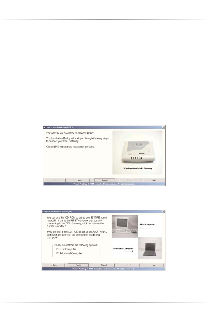
The instructions that follow parallel the steps contained in the Actiontec Installation
Buddy™,which provides a visual guide to setting up the Gateway. It is recommended
the user run the Installation Buddy first, before attempting any other procedures.
To set up the Gateway, it must be connected to a computer, and then configured.
After connecting this first computer, other computers can be added to the network
via USB,Ethernet, or wirelessly (see “Building a Network” on page 57).
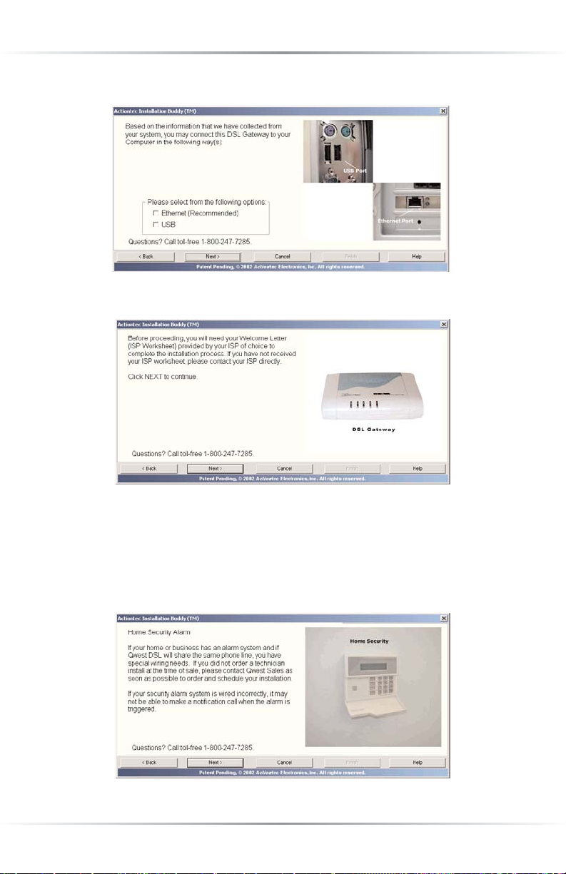
Warning!
Read the following two sections (Alarm System, Automatic Water Heater)
before proceeding with any installation!
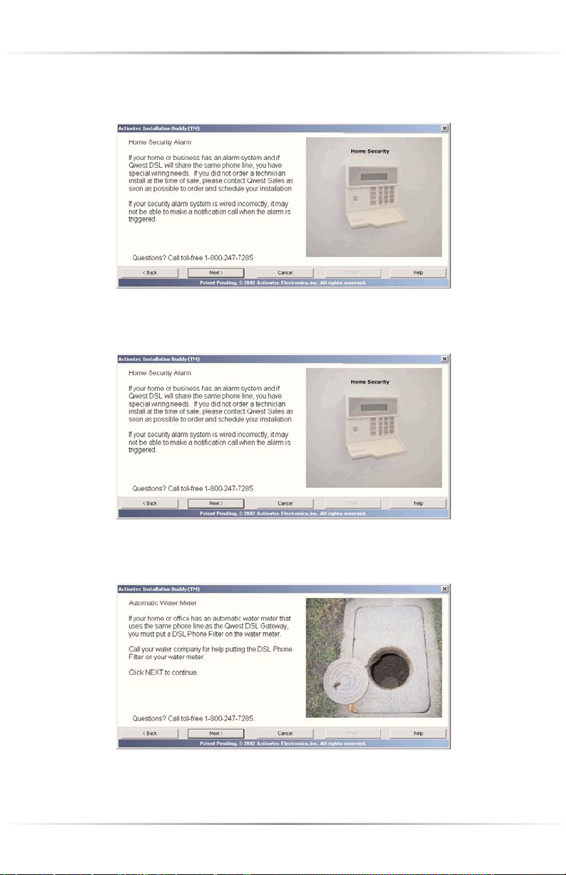
Alarm System
If your home or business has an alarm system and Qwest DSL shares the same
phone line, you have special wiring needs. If you did not order a technician install
at the time of sale, please contact Qwest Sales as soon as possible to order and
schedule your installation.
If you security alarm is wired incorrectly, it may not be able to make a notification
call when the alarm is triggered. Professional wiring is required to insure interoperability. Do not attempt the installtion yourself. Qwest strongly recommends that
you contact your security organization for more information about your security
alarm system before you attempt to install Qwest DSL. Qwest also strongly recommends that you contact your security organization after installing Qwest DSL to
have them conduct a test of your alarm system.
Automatic Water Meter
If your home or office has an automatic water meter that uses the same phone line
as the Qwest DSL Gateway, you must put a DSL Phone Filter on the water meter.
Call your water company for help when installing the DSL Phone Filter on your
water meter.
2
Page 9
6
Actiontec Wireless-Ready DSL Gateway User Manual
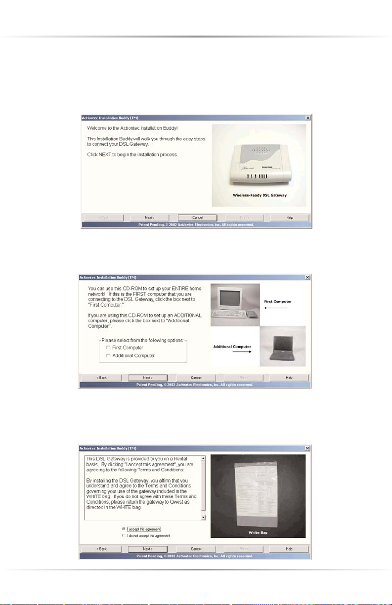
Connecting a Computer to the Gateway
Connecting a computer to the Gateway involves three basic steps: initial setup,
plugging in the Gateway’s Power Cord, and connecting the Gateway to the computer via Ethernet or USB cable. To connect this initial computer to the Gateway
using an Ethernet cable, follow the procedure that begins below. For USB connections, see “Connecting Via USB” on page 14.
☞
Note:The following procedures are for U.S. installations only.
Connecting Via Ethernet
1. Insert the Actiontec Installation Buddy CD-ROM in the CD-ROM drive of
the computer. The Installation Buddy will start automatically. Wait until the
following screen appears, read the onscreen instructions, then click Next.
2. The next window appears. Read the instructions, select First Computer by
clicking on the check box, then click Next.
Page 10
7
Chapter 2 Setting Up the Gateway
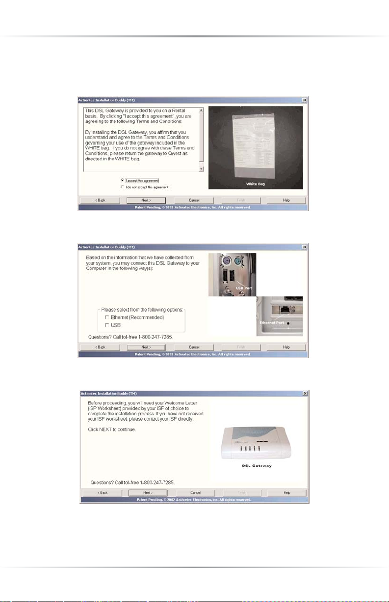
3. The next window appears. Read the onscreen information, then get the
“Terms and Agreement” document from the White Bag and read it as well.
Then, select I accept this agreement and click Next.
4. The next window appears. Select Ethernet, then click Next.
5. The next window appears. Read the onscreen instructions, then click Next.
☞
Note:You must have your Welcome Letter (ISP Worksheet) to
complete this installation. If you have not received this document, contact your ISP immediately.
Page 11
8
Actiontec Wireless-Ready DSL Gateway User Manual
6. When the next window appears, read the information concerning home
alarm systems, then click Next.
7. Another window concerning home alarms appears. Read the onscreen information, then click Next.
8. When the next window appears, read the information concerning automatic
water meters, then click Next.
Page 12
9
Chapter 2 Setting Up the Gateway
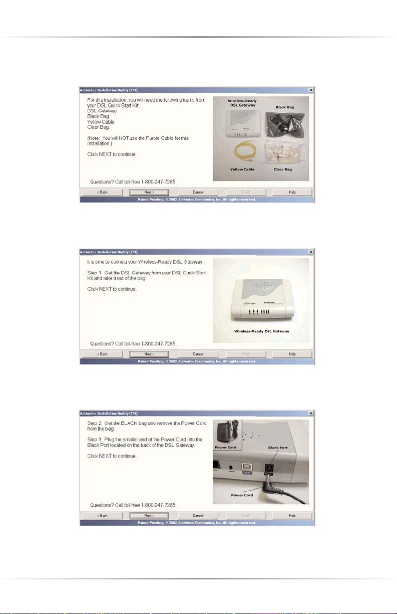
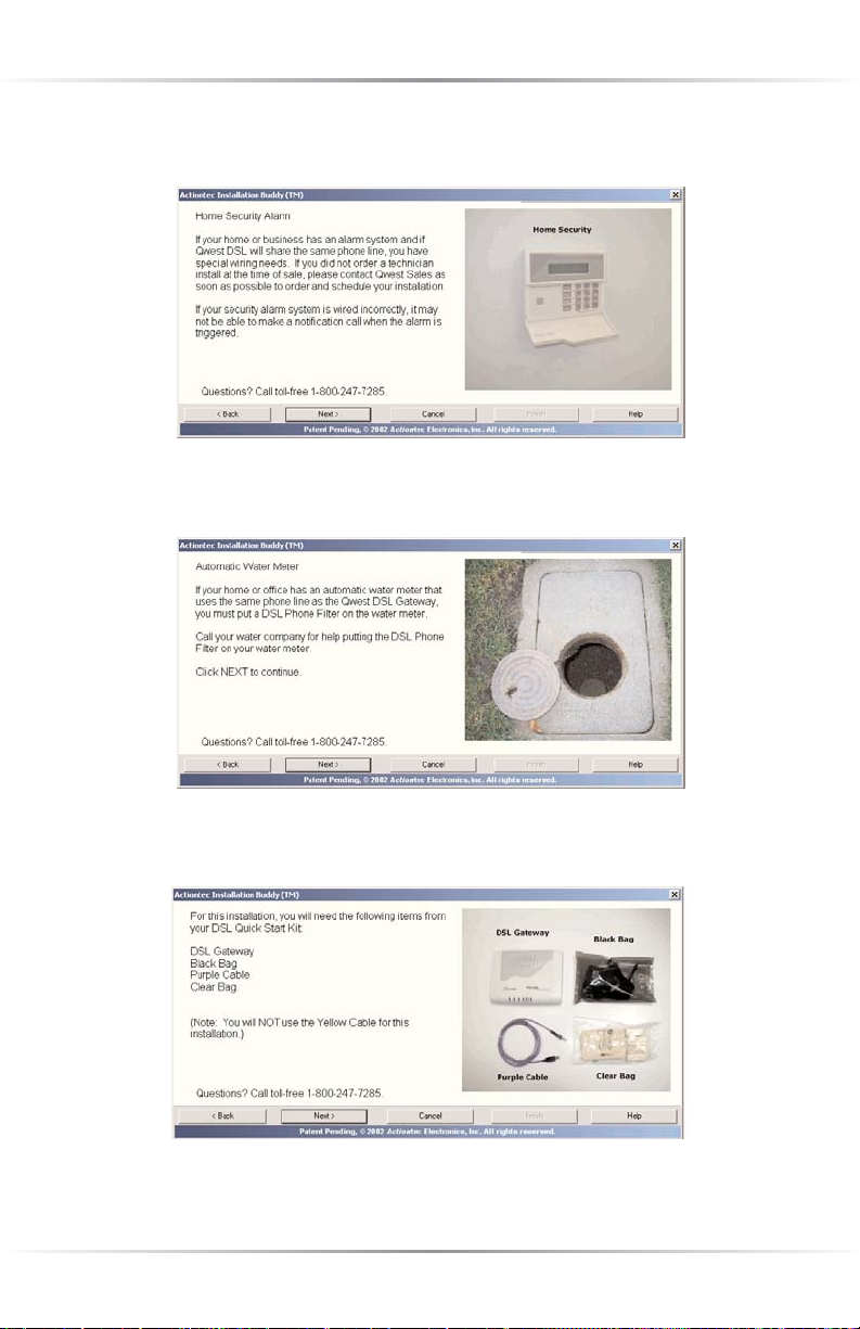
9. In the next window, read the instructions regarding the items needed to set up the
Gateway, then click Next.
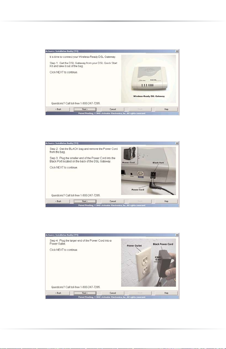
10. As shown in the next window, get the Gateway from the DSL Quick Start Kit,
then click Next.
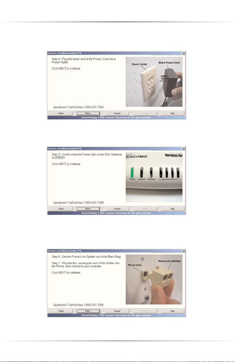
11. The next window appears. Plug the smaller end of the Power Cord into the
Black Port on the back of the Gateway, then click Next.
Page 13
10
Actiontec Wireless-Ready DSL Gateway User Manual
12. When the next window appears, plug the larger end of the Power Cord into a
Power Outlet, then click Next.
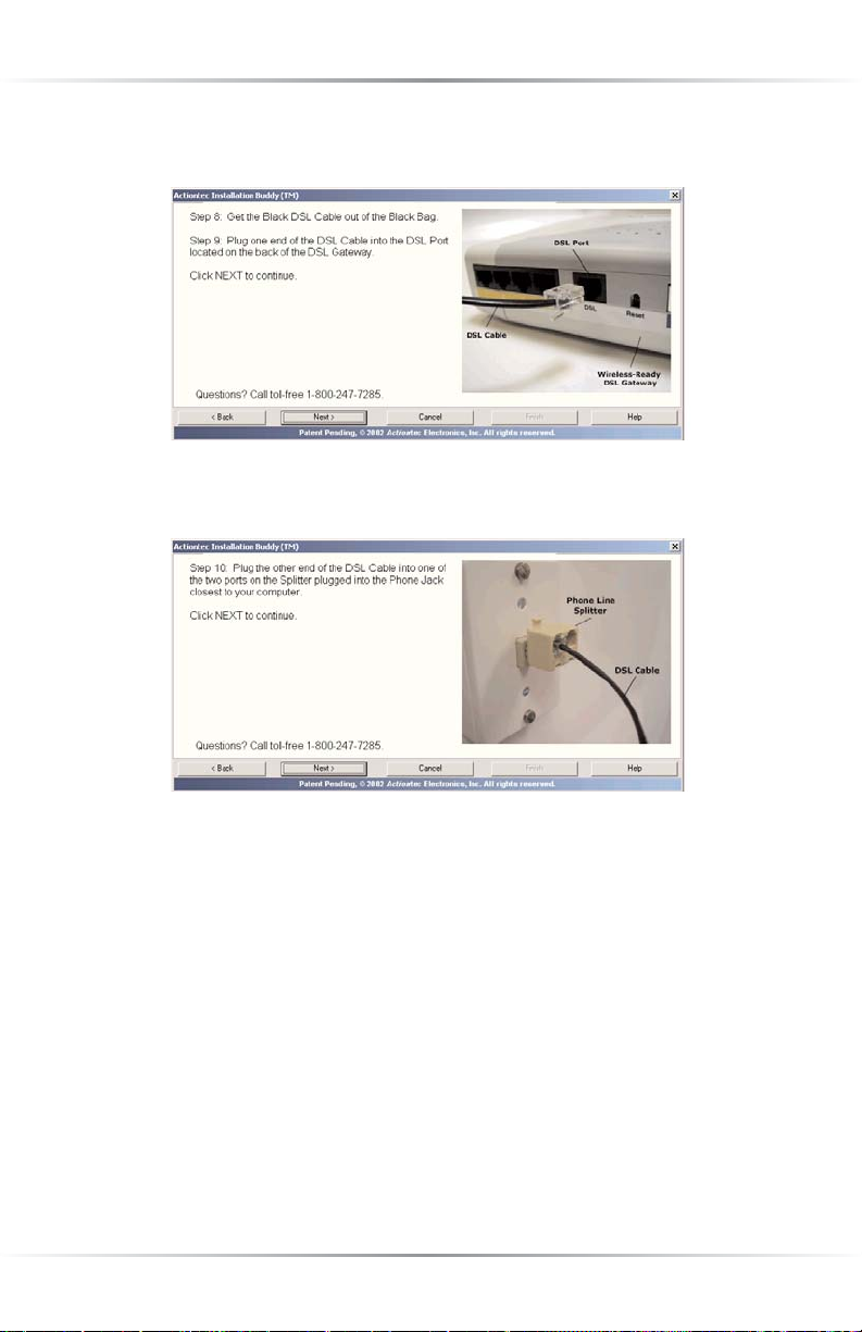
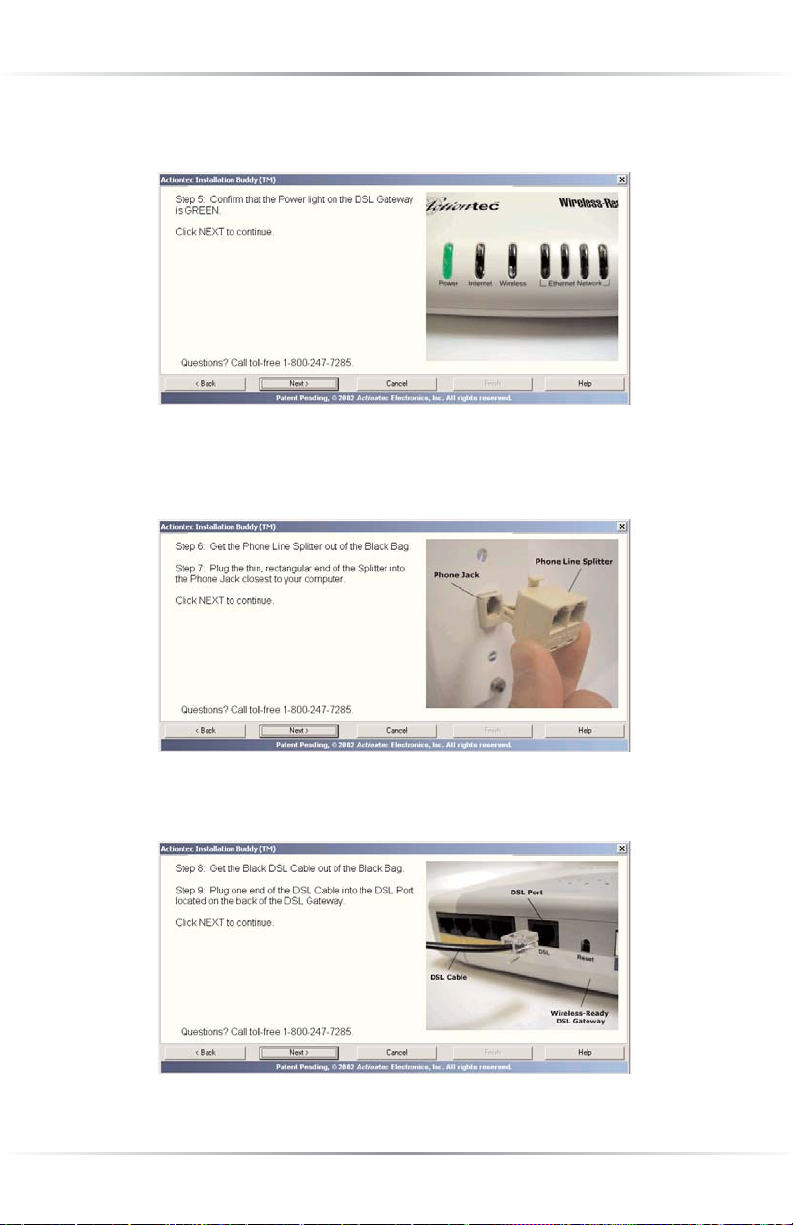
13. When the next window appears, confirm the Power Light on the Gateway
glows steadily green.Click Next.
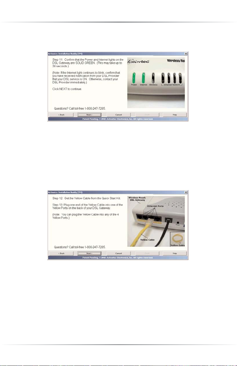
14. The following window appears. Get the Phone Line Splitter from the DSL
Quick Start Kit and plug it into the Phone Jack closest to the computer, then
click Next.
Page 14
11
Chapter 2 Setting Up the Gateway
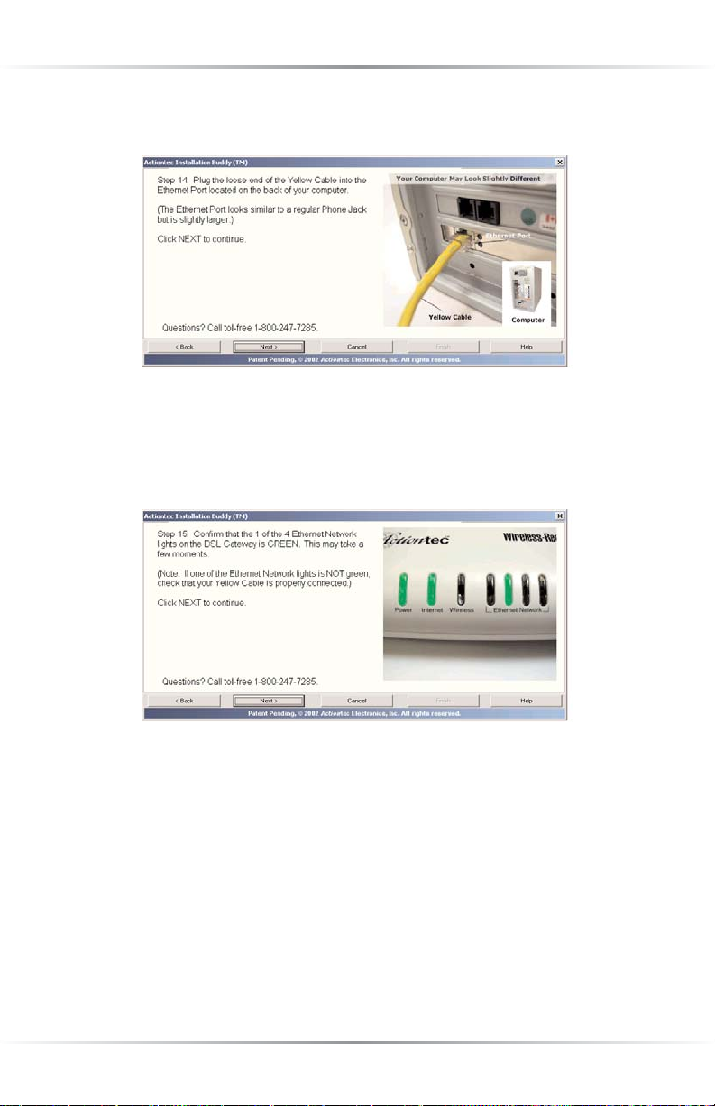
15. When the next window appears, get the Black DSL Cable and plug one end
of it into the DSL Port on the back of the Gateway, then click Next.
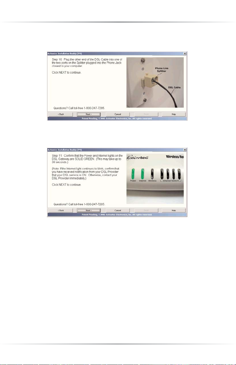
16. Another window appears. Plug the other end of the Black DSL Cable into one of
the two ports on the Splitter, then click Next.
Page 15
12
Actiontec Wireless-Ready DSL Gateway User Manual
17. When the next window appears, confirm the Power and Internet Lights on
the Gateway glow steadily green.Click Next.
☞
Note:Ifthe Power and Internet Lights on the Gateway are not
solid green, check all connections to the Gateway. If all connections are plugged in properly, call Qwest DSL Technical Support
at 1-800-247-7285.
18. In the next window, get the Ye l l o w E thernet Cable from the Quick Start Kit
and plug one end of it in one of the Ye ll o w Po rt s on the back of the Gateway.
Click Next.
Page 16
13
Chapter 2 Setting Up the Gateway
19. When the next window appears, plug the other end of the Ye l l o w E thernet
Cable into an Ethernet Port on the back of the computer. Click Next.
☞
Note:An Ethernet port looks similar to a phone jack, but is
slightly larger.
20. When the next window appears, make sure one of the four Ethernet
Network Lights glows solid green.
The Gateway is connected to a computer via Ethernet. Click Next to install the fil-
ters as described in “Installing the Filters” on page 21.
Page 17
14
Actiontec Wireless-Ready DSL Gateway User Manual
Connecting Via USB
1. Insert Act iontec Installation Buddy CD-ROM in the CD-ROM drive of the
computer. The Installation Buddy will start automatically. Wait until the following screen appears, read the onscreen instructions, then click Next.
2. The next window appears. Read the instructions, select First Computer by
clicking on the check box, then click Next.
3. The next window appears. Read the onscreen information, then get the
“Terms and Agreement” document from the White Bag and read it as well.
Then, select I accept this agreement and click Next.
Page 18
15
Chapter 2 Setting Up the Gateway
4. The next window appears. Select USB, then click Next.
5. The next window appears. Read the onscreen instructions, then click Next.
☞
Note:You must have your Welcome Letter (ISP Worksheet) to
complete this installation. If you have not received this document, contact your ISP immediately.
6. When the next window appears, read the information concerning home alarm
systems, then click Next.
Page 19
16
Actiontec Wireless-Ready DSL Gateway User Manual
7. Another window concerning home alarm systems appears. Read the onscreen
information, then click Next.
8. When the next window appears, read the information concerning automatic
water meters, then click Next.
9. In the next window, read the instructions regarding the items needed to set up the
Gateway, then click Next.
Page 20
17
Chapter 2 Setting Up the Gateway
10. As shown in the next window, get the Gateway from the DSL Quick Start Kit,
then click Next.
11. The next window appears. Plug the smaller end of the Power Cord into the
Black Port on the back of the Gateway, then click Next.
12. When the next window appears, plug the larger end of the Power Cord into a
Power Outlet, then click Next.
Page 21
18
Actiontec Wireless-Ready DSL Gateway User Manual
13. When the next window appears, confirm the Power Light on the Gateway
glows steadily green.Click Next.
14. The following window appears. Get the Phone Line Splitter from the DSL
Quick Start Kit and plug it into the Phone Jack closest to the computer, then
click Next.
15. When the next window appears, get the Black DSL Cable and plug one end
of it into the DSL Port on the back of the Gateway, then click Next.
Page 22
19
Chapter 2 Setting Up the Gateway
16. Another window appears. Plug the other end of the Black DSL Cable into one of
the two ports on the Splitter, then click Next.
17. When the next window appears, confirm the Power and Internet Lights on
the Gateway glow steadily green.Click Next.
☞
Note:Ifthe Power and Internet Lights on the Gateway are not
solid green, check all connections to the Gateway. If all connections are plugged in properly, call Qwest DSL Technical Support
at 1-800-247-7285.
Page 23
20
Actiontec Wireless-Ready DSL Gateway User Manual
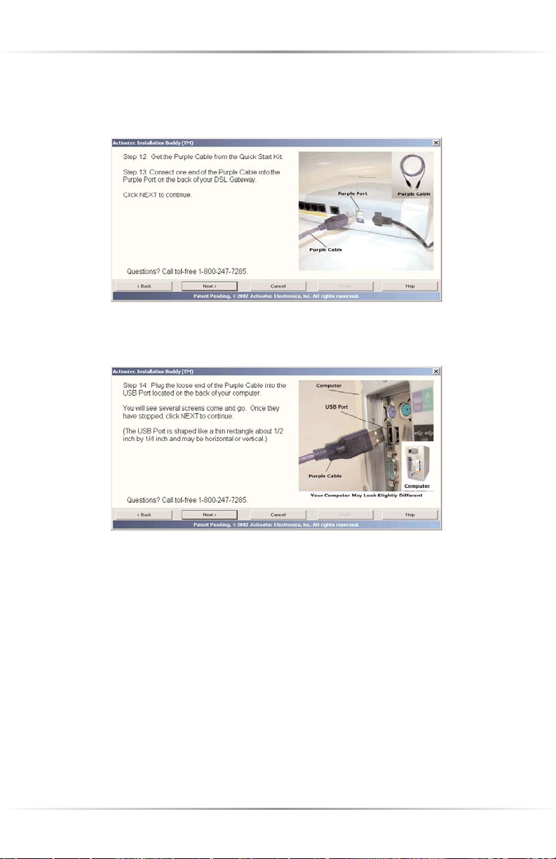
18. In the next window, get the Purple USB Cable from the Quick Start Kit and
plug the square end of it in the Purple Port on the back of the Gateway.
Click Next.
18. When the next window appears, plug the rectangular end of the Purple USB
Cable into a USB Port on the front or back of the computer. Click Next.
☞
Note:A USB port is shaped like a thin rectangle about 1/4 inch
by 1/2 inch, and may be vertically or horizontally oriented.
The Gateway is connected to a computer via USB. Click Next to install the filters as
described in “Installing the Filters” on page 21.
Page 24
21
Chapter 2 Setting Up the Gateway
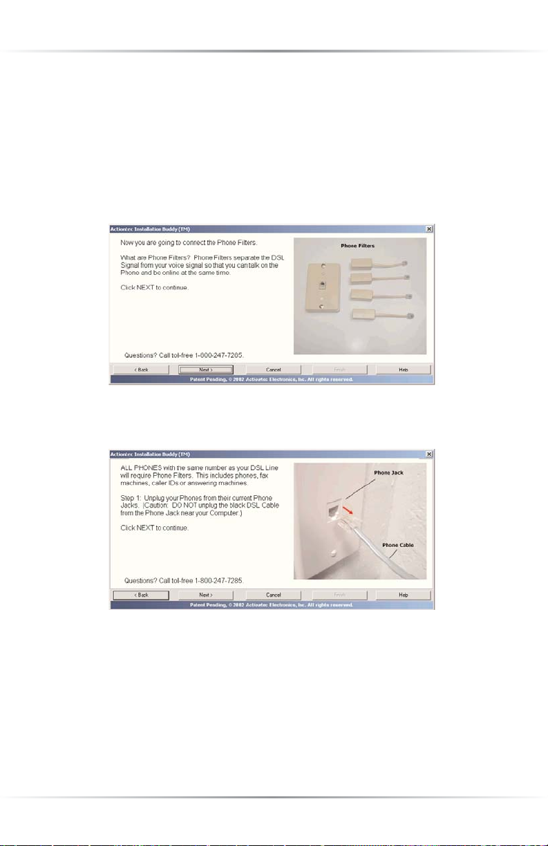
Installing Filters
Filters allow the user to talk on the phone while online. All phones and other
devices (answering machines, fax machines, etc.) using the same line (i.e., using
the same phone number) as the DSL line must have a filter installed. To install a
filter, follow these instructions:
1. When the following window appears, read the onscreen instructions, then
click Next to continue.
2. When the next window appears, unplug all phone cords from their respective
phone jacks, then click Next.
Caution: Do not unplug the black DSL cable from the phone
jack near your computer.
Page 25
22
Actiontec Wireless-Ready DSL Gateway User Manual
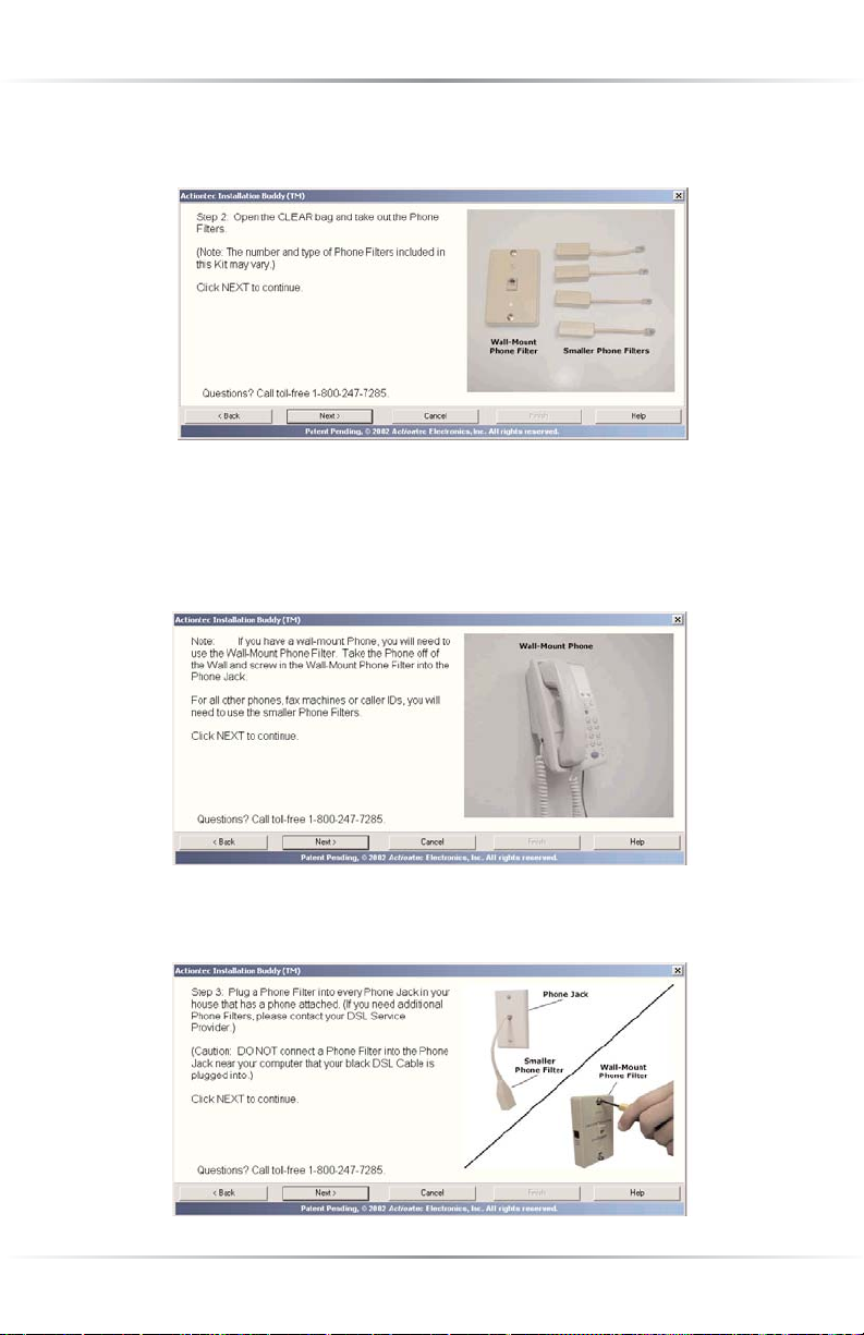
3. When the following window appears, get the Clear Bag, take out the phone filters, then click Next.
Caution: Do not install a filter in the phone jack used by the
black DSL cable.
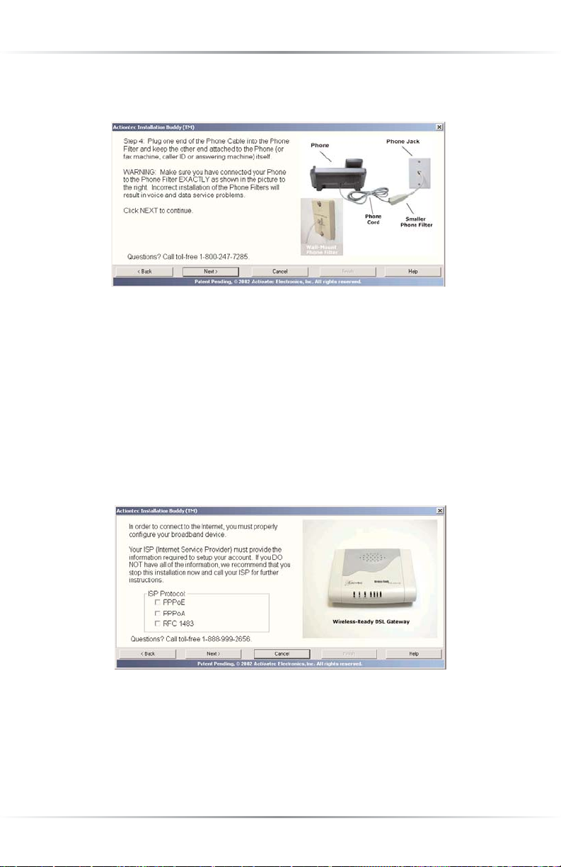
4. In the next window, read the onscreen instructions concerning wall-mount phones.
Click Next.
5. After the next window appears, plug a Phone Filter into ever
Phone Jack that
has a device (phone, fax machine, answering machine, etc.), then click Next.
Page 26
23
Chapter 2 Setting Up the Gateway
6. When the next window appears, read the onscreen instructions on how to
connect the phone filters, then click Next.
The phone filters are installed. Click Next.to go to “Setting Up the DSL
Connection,” as described below.
Setting Up the DSL Connection
After connecting the Gateway and installing phone filters, the DSL connection
must be configured. Use the following procedure:
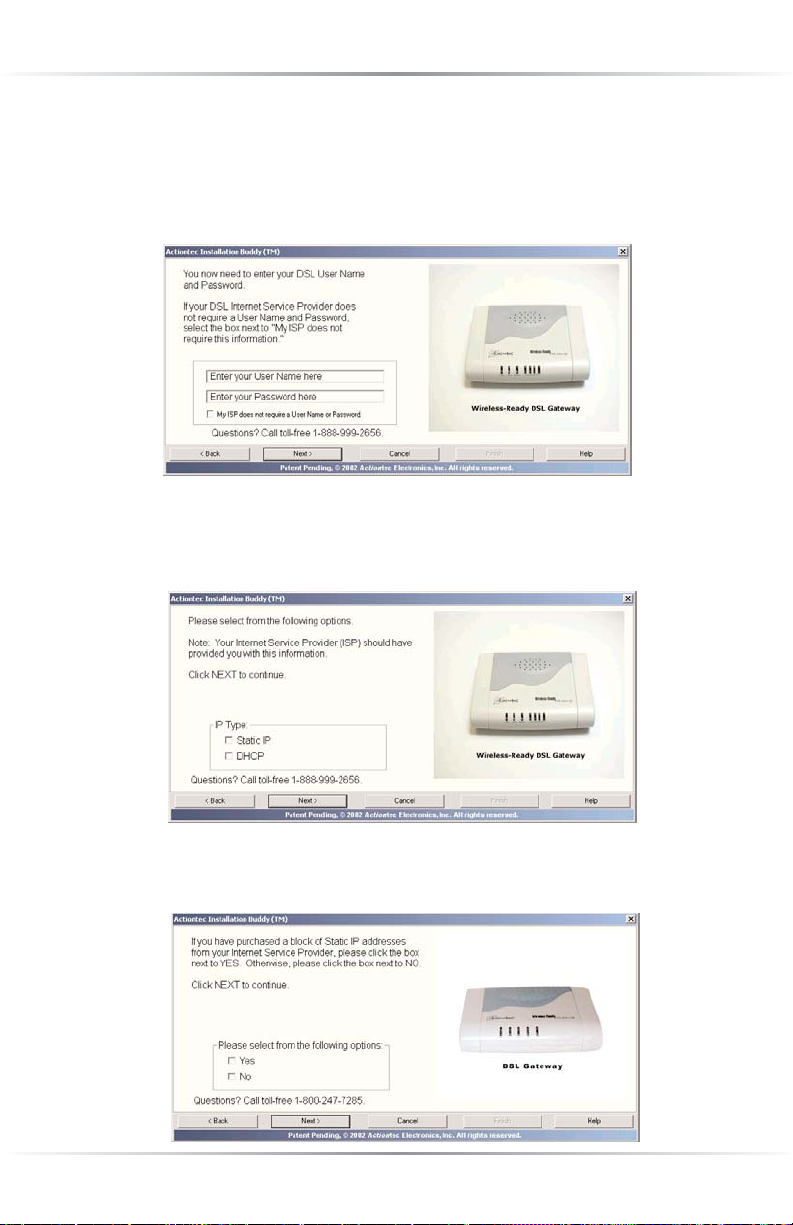
1. When the window below appears, read the onscreen instructions and, if the
information needed is available, select the type of ISP Protocol to be used.
Click Next.
Page 27
24
Actiontec Wireless-Ready DSL Gateway User Manual
2. If PPPoE or PPPoA was selected, the following window appears. Enter the
User Name and Password in the proper text boxes, or, if the ISP does not
require them, click the box next to “My ISP does not require a User Name or
Password.” Click Next.
If RFC 1483 was selected, go directly to step 3.
3. The next window appears. Select the IP type used by the ISP.
Click Next.
If DHCP was selected, go directly to step 6
4. The next window appears. Read the onscreen instructions concerning purchased blocks of Static IP addresses, select the proper option, then click Next.
Page 28
25
Chapter 2 Setting Up the Gateway
5. When the next window appears, enter the IP Address, Subnet, Gateway, DNS
1, and DNS 2 information in the proper text boxes. This information should
be provided by the ISP. When finished, click Next.
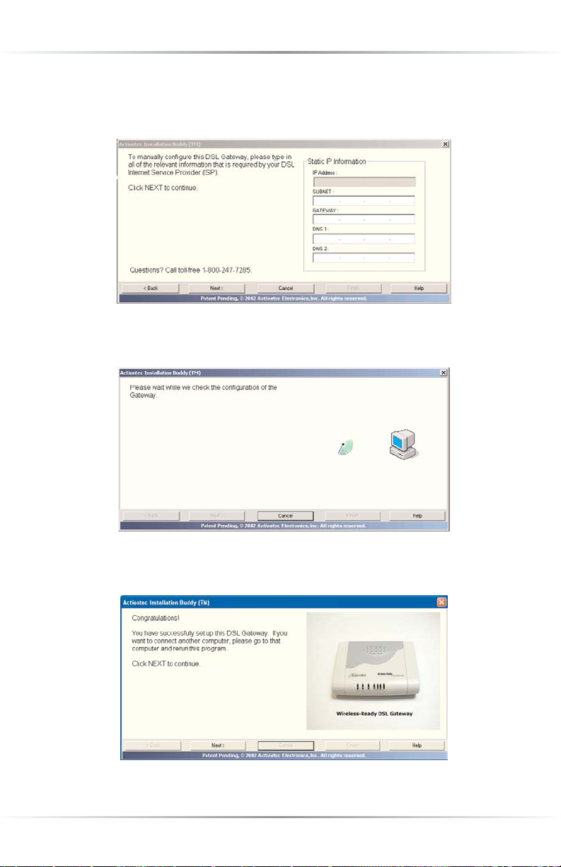
6. In the next window, the Installation Buddy checks the configuration of
the Gateway.
7. A “Congratulations!” window appears. Read the onscreen instructions, then
click Next.
Page 29
26
Actiontec Wireless-Ready DSL Gateway User Manual
8. In the next window, read the onscreen information about computer security,
then click Next.
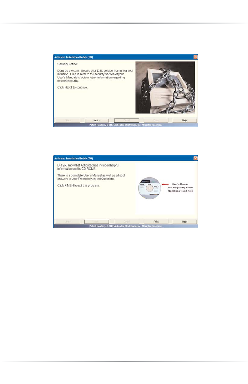
9. In the last window, read the onscreen information regarding additional reference material on the CD-ROM, then click Finish.
The Gateway has been successfully configured.
Page 30

27
Using Qwest DSL
Qwest DSL operates over home or business phone lines equipped with Qwest DSL
service. For this reason, the Qwest DSL connection is not portable; it can’t be
accessed while away from home or business. To connect while traveling, ask the
ISP about a dial-up account. Most Qwest DSL ISPs provide a dial-up account for
free, while others charge a minimal fee.
Qwest DSL is a highly reliable service, but it is possible to have a dial-up connection in the unlikely event that problems arise with the DSL service. Most Qwest
DSL ISPs provide a dial-up account for free. If not, there are a number of free
Internet providers whose products make great backup Internet access in the
unlikely event they are ever needed.
Connecting to the Internet
Whether connecting via Point-to-Point Protocol (PPPoE, PPPoA) or Bridging
Mode (RFC 1483), after connecting and configuring the Gateway, the Internet
connection is always on. Therefore, to connect or reconnect to the Internet, simply
turn on your computer, open the Web browser and go to the Web site of your
choice. No further set up is needed.
Disconnecting from the Internet
To disconnect from the Internet, close the Web browser. To completly disengage,
turn off the computer.
3
Page 31

28
Actiontec Wireless-Ready DSL Gateway User Manual
Page 32

29
Basic Setup
This chapter is a guide through a basic configuration of the Gateway, including
how to connect the Gateway to the ISP, as well as an overview of the Gateway’s
LEDs and switches.
To complete the basic setup, the user will need the Welcome Letter (ISP
Wo r ksheet). If the document is not available, contact the ISP immediately.
Basic Setup
To configure the gateway for basic operation:
1. Open the Web browser. In the address bar, enter
http://192.168.0.1
then press Enter on the keyboard.
2. The “Main Menu” screen appears. Select Setup/Configuration.
4
Page 33

30
Actiontec Wireless-Ready DSL Gateway User Manual
3. Follow the instructions in the “Set Up/Configuration” screen, then click Begin
Basic Setup.
4. In the next window, follow the onscreen instructions, then click Next.
5. In the next window, select the type of connection by clicking on the circle
next to PPPoA or PPPoE.Ifunsure about the selection, contact the ISP.
Page 34

31
Chapter 4 Basic Setup
6. Enter the User Name, Password, and Static IP provided by the ISP in the
“DSL Broadband Connection - PPP” screen. Click Next.
☞
Note:Ifthe ISP uses a connection method other than PPPoE
(DHCP or Static IP, for example) see “Advanced Setup” to connect the Gateway.
7. Click Save and Restart in the “Save and Restart” screen.
8. The “Congratulations” screen appears. The Gateway is successfully configured.
The Power Light flashes rapidly while the Gateway restarts, then glows steadily
green when fully operational. The Internet Light will also glow steadily green. The
Gateway is now configured and users can start surfing the Web.
If an error stating the Web browser was unable to connect to the Internet appears,
check the configuration settings. Ensure all the information required by the ISP is
entered correctly.
Page 35

32
Actiontec Wireless-Ready DSL Gateway User Manual
Gateway Features
This section contains a quick description of the Gateway’s lights and switches.
Power Light - The Power Light displays the Gateway’s current status. If the Power
Light glows steadily green, the Gateway is receiving power and fully operational.
When the Power Light is rapidly flashing, the Gateway is initializing. If the Power
Light is not illuminated when the power cord is plugged in, the Gateway has suffered a critical error and technical support should be contacted.
Internet Light - When the Internet Light glows steadily, the Gateway is connected
to the DSL provider. When it flashes, data is being send via the WAN port.
Wireless Light - When the Wireless Light glows steadily, the Gateway is ready for
wireless networking.
Ethernet Network Light - The Ethernet Network Light s glow when a network
link is established with a computer. A flashing Light signifies network traffic across
the specific Ethernet connection.
Reset Switch - Depressing the reset switch for one or two seconds will power cycle
(similar to unplugging and then plugging in the Gateway’s power cord) the
Gateway. To restore the Gateway’s factory default settings, depress and hold the
Reset Switch for approximately 10 seconds. The reset process will start about 10
seconds after releasing the Reset Switch.
Wa rning:Do not unplug the power cord from the Gateway
during the reset process. Doing so may result in permanent
damage to the Gateway.
Page 36

33
Advanced Setup
This section contains information concerning advanced configuration, such as
wireless settings, remote management, and Web site blocking.
Accessing Advanced Setup
To access the Advanced Setup configuration screens, follow these instructions:
1. Open the Web browser. In the address bar enter:
http://192.168.0.1
then press Enter on the keyboard.
2. The “Main Menu” screen appears. Select Setup/Configuration.
3. In the “Set Up/Configuration” screen, read the instructions, then select
Advanced Setup from the menu on the left side.
5
Page 37

34
Actiontec Wireless-Ready DSL Gateway User Manual
4. In the next screen, read the recommendations. To perform an advanced setup
on the Gateway, click Begin Advanced Setup.
5. The “Configuring the Advanced Settings” screen appears. To check all the set-
tings, or if unsure of which settings to modify, select Next.To modify a specif-
ic configuration, click on its name in the menu bar on the left.
Using Advanced Setup
To select a particular setting, click on it in the gray menu on the left side of the
Configuring the Advanced Settings screen. When the setting has been changed,
click Save and Restart at the bottom of the gray menu to save the setting.
However, if more than one setting needs to be changed, click Save and Restart after
all changes have been made.
Clicking Next in an Advanced Setup screen generates the next Advanced Setup
screen, in the order they appear in the gray menu. Changes in the previous
Advanced Setup screen will be saved temporarily. When finished, click Save and
Restart.
Page 38

35
Chapter 5 Advanced Setup
☞
Note:Ifchanges have been made to one or more Advanced
Setup settings and Save and Restart has not been clicked before
leaving the Advanced Setup screens (i.e., switching to Utilities or
Basic Setup), all Advanced Setup settings changes will be lost.
WAN IP Address
Selecting WAN IP Address in the “Advanced Configuration” screen generates the
“WAN IP Address” screen.
WAN IP Address allows manual set up of the IP address
of the Gateway. There are four ways to do this: Transparent Bridging, Obtain an
IP Address through
PPPoE/PPPoA
, Obtain an IP
Address Through DHCP
, and
Specify a Static IP Address.
☞
Note:Some DSL providers use PPPoE/PPPoA to establish com-
munication with an end user, while others use static IP.Some
types of broadband Internet connections (such as fixed point
wireless) may use either DHCP or Static IP address. If unsure
about which connection is present, check with the Internet
Service Provider (
ISP) before continuing.
After selecting a connection type, click Next to continue configuring the connection.
Page 39

36
Actiontec Wireless-Ready DSL Gateway User Manual
Transparent Bridging
Select this option to use the Gateway as a transparent bridge only if directed to do
so by your ISP. This option should only be used if the Gateway is being used as a
Modem to connect one computer to the Internet via a DSL connection. When the
Gateway is being used as a transparent bridge, it does not provide any firewall
security.
Obtain an IP Address through PPPoE or PPPoA
Select this option to allow the Gateway to use the Point-to-Point over Ethernet
(PPPoE) or Point-to-Point over ATM (PPPoA) protocol.
If a User Name, Password and/or Static IP was entered during Basic Setup, it
should be displayed in the “Broadband Connection via PPPoE/PPPoA” screen. If
not, enter the information now. If the information is unavailable, contact your
Internet Service Provider (ISP).
Obtain an IP Through DHCP
Select this option to allow the modem to query the Internet Service Provider (
ISP)
and receive
IP address and routing information. Some ISPs need to authenticate
their end users with a Host Name and/or Domain Name.Ifthis is the case, check
with the
ISP for a host name and domain name and enter them in the “Broadband
Connection via DHCP” screen. If the ISP does not require these settings, leave the
text boxes blank.
Page 40

37
Chapter 5 Advanced Setup
☞
Note:Host and domain name information may also be accessed
from the computer originally connected to the DSL modem.
Specify a Static IP Address
Select this option if assigned a static (specific)
IP Address by the Internet Service
Provider (ISP). Enter the IP Address, along with the Subnet Mask and Default
Gateway Address (also provided by the ISP), in the “Broadband Connection via
Static IP Address” screen. If required to provide a Host Name and Domain Name,
enter them here as well.
Page 41

38
Actiontec Wireless-Ready DSL Gateway User Manual
Unnumbered/VIP Mode
If the user has purchased a block of static IP addresses, select Unnumbered Mode
by clicking on the box. Then, enter the IP address and Subnet Mask assigned to the
Gateway in the “Gateway Address” and “Unnumbered Subnet Mask” text boxes
below “Unnumbered IP Address.” This information should be sent to the user
when purchasing a block of static IP addresses.
VIP mode reserves the DHCP server for any computer connected to the Gateway
configured to use a DHCP server. When VIP mode is activated, all computers
using static IP addresses must be configured separately to use a static IP address.
After changing settings, click Next or Back to continue, or Save and Restart to
make all changes permanent.
Wireless Settings
Selecting Wireless Settings in the “Advanced Configuration” screen generates the
“Wireless Settings” screen. Modify the wireless capabilities of the Gateway here.
ESSID
ESSID is the network name assigned to the wireless network. The factory default
setting is “ACTIONTEC.” Although Act iontec recommends keeping the default
value intact, the ESSID value can be modified, using any combination of alphanumeric characters (i.e., A-Z, a-z, 0-9). All wireless-capable computers included on
the Gateway’s wireless network must have this same ESSID value. (For the Actiontec
802.11b Wireless PC Card, the ESSID value must be the same as the SSID value.)
Page 42

39
Chapter 5 Advanced Setup
Channel
Channel assigns the frequency band at which the Gateway communicates. In the
United States, use channels 1-11. (The factory default value is set to 1.)
Wireless Equivalent Privacy
Wireless Equivalent Privacy (WEP) is an encryption method used with the 802.11b
standard to provide limited data security over wireless networks. The Gateway
offers three levels of WEP: Off, 64-bit, and 128-bit. Qwest recommends setting up
WEP to offer some security to your wireless connection.
Off
Selecting Off disables encryption. Selecting this option offers minimal protection and allows any computer with wireless capability and the correct ESSID
value to join the wireless network.
64-bit WEP
64-bit WEP requires four separate keys. Each key comprises five hexadecimal
digit pairs. A hexadecimal digit consists of an alphanumeric character ranging
from 0-9 or A-F. An example of a 64-bit WEP key is: 4E-A3-3D-68-72. To create
a set of 64-bit WEP keys, enter five hexadecimal digit pairs in each Key text box
(Key 1-, Key 2-, Key 3-, Key 4-). After activating 64-bit WEP on the Gateway, a
computer with wireless capability can join the network only if these same keys
are entered in the computer’s wireless encryption scheme. 64-bit WEP offers
more security than Off under most circumstances
Page 43

40
Actiontec Wireless-Ready DSL Gateway User Manual
128-bit WEP
128-bit WEP requires one key of 13 hexadecimal pairs. A hexadecimal digit consists of alphanumeric characters ranging from 0-9 or A-F. An example of a 128-bit
WEP key is: 3D-44-FE-6C-A1-EF-2E-D3-C4-21-74-5D-B1. To create a 128-bit
WEP key, enter 13 hexadecimal digit pairs in the Key text box. After activating 128-
bit WEP
on the Gateway, a computer with wireless capability can join the network
only if this key is entered in the computer’s wireless encryption scheme.128-bit
WEP offers greater security than 64-bit WEP under most circumstances
☞
Note:Not all wireless
PC Cards support 128-bit WEP. Ensure
that all
PC Cards installed in the networked computers support
128-bit WEP before activating.
After changing settings, click Next or Back to continue, or Save and Restart to
make all changes permanent.
Important:Wireless networking devices use public radio channels to transmit voice and data communications. Although WEP
is the standard security technology used today and offers some
degree of security, Qwest cannot guarantee the security, privacy,
or confidentiality of any transmissions made via such devices,
and Qwest makes no assurances or warranties relating to their
use by you. You are responsible for all use of your Qwest DSL
service, regardless of the source of a transmission, whether by
you or an authorized third party, over your Qwest DSL service.
Page 44

41
Chapter 5 Advanced Setup
LAN IP Address
Selecting LAN IP
Address in the “Advanced Configuration” screen generates the
“LAN IP Address” screen. The value in the
LAN IP
Address text box is the IP
address of the Gateway as seen on the network.
The
LAN IP address of the Gateway can be modified, but Actiontec recommends
keeping the default factory setting (192.168.0.1).
☞
Note:Ifthe Gateway’s LAN IP Address is modified, verify the
DHCP Server range is within the same subnet. For more infor-
mation, see “DHCP Server Configuration.”
After changing settings, click Next or Back to continue, or Save and Restart to
make all changes permanent.
DHCP Server
Selecting DHCP Server in the “Advanced Configuration” screen generates the
“DHCP Server” screen. The Gateway has a built-in DHCP (Dynamic Host
Configuration Protocol) server that automatically assigns a different IP address to
each computer on the network, eliminating IP address conflicts.
The factory default setting is On.To disable the DHCP Server, select Off.
Page 45

42
Actiontec Wireless-Ready DSL Gateway User Manual
Actiontec strongly recommends leaving the
DHCP Server option On.Ifthe DHCP
Server option is Off,ensure the
IP addresses of the networked computers are on
the same subnet as the IP address of the Gateway. For more information, see
“DHCP Server Configuration” on page 42.
DHCP Server Configuration
Clicking Next in the “DHCP Server” screen generates the “DHCP Server
Configuration” screen. Change IP address range and DNS server information here.
Beginning
IP Address - the IP address at which the DHCP server
starts assigning IP addresses. Actiontec recommends keeping the
factory default setting (192.168.0.2).
Ending IP Address - the IP Address at which the DHCP Server stops
assigning IP addresses. Actiontec recommends keeping the factory default settings (192.168.0.254).
The beginning and ending IP addresses define the IP address range of the
Gateway. If the default values are left intact, the Gateway supplies a unique IP
address between 192.168.0.2 and 192.168.0.254 to each computer on the network.Note that the first three groups of numbers of the addresses are identical;
this means they are on the same subnet. The IP address of the Gateway must be
on the same subnet as the IP address range it generates. For instance, if the
Gateway’s IP address is changed to 10.33.222.1, set the beginning IP address to
10.33.222.2, and the ending IP address to 10.33.222.254.
DNS (Dynamic or Static) - the type of DNS server provided by the
Internet Service Provider (ISP).Ifthe ISP provided DNS server
information, select the type here. If not, leave as is.
DNS
Server 1 - the primary DNS server provided by the Internet
Service Provider (ISP).Ifthe ISP provided DNS server informa-
tion, enter it here. If not, leave the text box intact.
Page 46

43
Chapter 5 Advanced Setup
DNS
Server 2 - the secondary DNS provided by the Internet Service
Provider (ISP).Ifthe ISP provided secondary DNS server information, enter it here. If not, leave the text box intact.
After changing settings, click Next or Back to continue, or Save and Restart to
make all changes permanent.
Services Blocking
Selecting Services Blocking in the “Advanced Configuration” screen generates the
“Services Blocking” screen.
To modify Internet privileges (Web,
FTP,Newsgroups, etc.) for the computers on
the network:
1. Enter the computer’s IP address in the Enter IP Address: text box.
2. Select the Internet service(s) to be blocked.
3. Click Add to enter the computer’s IP address in the “Blocked IP Address List”
text box.
4. To remove blocked services, select the computer’s IP address in the “Blocked
IP Address List” text box and click Remove.
Page 47

44
Actiontec Wireless-Ready DSL Gateway User Manual
Netmeeting
To allow the computers on the Gateway’s network to access Netmeeting, enter the
Netmeeting IP address (LAN IP address using Netmeeting) in the IP text box,
then select On.IfNetmeeting is not needed, select Off.
After changing settings, click Next or Back to continue, or Save and Restart to
make all changes permanent.
Website Blocking
Selecting We bsite Blocking in the “Advanced Configuration”screen generates the
“Website Blocking” screen. This feature, which works only with NAT IP addressing, enables the Gateway to block Web sites to all computers on the network. To
block a Web site, enter the address of the Web site in the “Website” text box and
click Add.The blocked Web site address will be displayed in the “Blocked Website
List” text box, and will not be available to computers on the network. To remove a
blocked Web site, click on it in the “Blocked Website List,” then click Remove.
After changing settings, click Next or Back to continue, or Save and Restart to
make all changes permanent.
VPN Pass Through
Selecting VPN
Pass Through in the “Advanced Configuration” screen generates
the “
VPN Pass Through” screen. To set up Virtual Private Networking (VPN) using
IPSec/L2TP (which allows multiple, client-initiated VPN pass-through sessions),
select On.Four VPN connections can be used at one time. Note that VPN via PPTP
pass through is always active.
Page 48

45
Chapter 5 Advanced Setup
After changing settings, click Next or Back to continue, or Save and Restart to
make all changes permanent.
Remote Management
Selecting Remote Management in the “Advanced Configuration” screen generates
the “Remote Management” screen. Remote Management allows access to the
Gateway through the Internet via another computer. Actiontec recommends leav-
ing the Remote Management Off (the factory default setting).
To access the Gateway from the Internet, activate Remote Management by selecting
On and writing down the
WAN IP address of the Gateway (see “WAN IP Address”).
On a computer outside of the network, open a Web browser and enter the
Gateway’s WA N I P address in the address text box. The Gateway’s Main Menu (or a
password prompt, if a password has been set) appears in the browser window.
☞
Note:Before Remote Management can be activated, the administrator password must be set. To do this, go to the Basic Setup
screen and select Change Admin Password. Follow the instructions in the subsequent screens
After changing settings, click Next or Back to continue, or Save and Restart to
make all changes permanent.
Page 49

46
Actiontec Wireless-Ready DSL Gateway User Manual
Port Forwarding
Selecting Port Forwarding in the “Advanced Configuration” screen generates the
“Port Forwarding” screen. Port forwarding allows certain programs to bypass the
Gateway’s built-in firewall, allowing access to parts of the network (for hosting a
We b or ftp server, for example). To use port forwarding, enter the IP port range in
the “IP Port Range” text boxes. (If more than 10 ports are needed, Act iontec rec-
ommends using DMZ Hosting. See “DMZ Hosting,” below, for more information.)
Choose the protocol type from the “Protocol” list box, then enter the IP address of
the computer on the network to be used as a host. Click Add.The forwarded ports
appear in the “List of Forwarded Ports” text box. For a list of programs that use
port forwarding, as well as port numbers used, see “Appendix C - Program and
Port List.”
To remove forwarded ports, highlight them, then click Remove.
Clicking Advanced brings up the “Advanced Port Forwarding” screen.
Page 50

47
Chapter 5 Advanced Setup
In this screen, the user can allow only certain IP addresses to access forwarded
ports. Enter the port range of the forwarded ports in the “Remote IP Port Range”
text boxes, enter the IP address to be allowed access in the “Remote IP Address”
text box, then click “Add.” The active forwarded ports will appear in the “List of
Forwarded Ports” text box.
To deactivate a forwarded port, select it from the “List of Forwarded Ports” text
box, then click “Remove.”
After changing settings, click Next or Back to continue, or Save and Restart to
make all changes permanent.
DMZ Hosting
Selecting DMZ Hosting in the “Advanced Configuration” screen generates the
“DMZ Hosting” screen. To use DMZ hosting, enter the IP address of the computer
on the network to be used as a DMZ host in the “DMZ Host IP Address” text box,
then click On.
Page 51

48
Actiontec Wireless-Ready DSL Gateway User Manual
DMZ hosting is used to support online gaming and Internet conferencing services.
These programs usually require multiple open ports, making the network accessible from the Internet. DMZ hosting symbolically places the DMZ host computer
outside of the Gateway’s network. Access to the network resources while DMZ
hosting is active is blocked. Act iontec recommends activating DMZ hosting only as
long as necessary.
Wa rning:The
DMZ
Host computer will be vulnerable to com-
puter hackers on the Internet while in DMZ mode.
After changing settings, click Next or Back to continue, or Save and Restart to
make all changes permanent.
Firewall
Selecting Firewall in the “Advanced Configuration” screen generates the “Firewall
Security Level
” screen.Select the level of security needed for the network. See
Appendix E for details concerning each level of security.
After changing settings, click Next or Back to continue, or Save and Restart to
make all changes permanent.
Page 52

49
Chapter 5 Advanced Setup
Dynamic Routing
Selecting Dynamic Routing in the “Advanced Configuration”screen generates the
“
Dynamic Routing” screen. Dynamic routing allows the exchange of routing tables
between routers. This relieves the user of having to set up static routes for each router.
If a router is set up behind the Gateway in the network configuration, consult the
documentation that came with the router to see what kind of Dynamic Routing is
required, then select the needed option.
After changing settings, click Next or Back to continue, or Save and Restart to
make all changes permanent.
NAT (Network Address Translation)
Selecting NAT in the “Configuring the Advanced Settings” screen generates the
“NAT” screen. The Gateway’s basic firewall security is based on NAT. This protocol
allows computers to use different IP addresses when connected to the Gateway,
and prevents outside users from easily accessing computers on the network.
Wa rning:Disabling NAT allows the computers connected to the
Gateway to be accessed by outside parties. Do not turn NAT off
unless instructed to do so by the Internet Service Provider (ISP).
Page 53

50
Actiontec Wireless-Ready DSL Gateway User Manual
After changing settings, click Next or Back to continue, or Save and Restart to
make all changes permanent.
Static Routing
Selecting Static Routing in the “Configuring the Advanced Settings” screen generates the “Static Routing” screen. Static Routing allows the user to manually create
routes to other networks connected to the Gateway. Other networks may include
routers or computers connected to the Gateway which are configured to reside in a
network other than the Gateway’s default network.
Enter the addresses in their respective text boxes, then click Add.The address will
appear in the “Static Routing Table.” To remove an address, highlight it by clicking
on it in the Static Routing Table, then click Remove.
After changing settings, click Next or Back to continue, or Save and Restart to
make all changes permanent.
Page 54

51
Chapter 5 Advanced Setup
MAC Address Cloning
Selecting MAC
Address Cloning in the “Advanced Configuration” screen generates
the “MAC Address Cloning” screen. A MAC (media access control) address is an
identifier unique to every networkable device.Some Internet Service Providers
(
ISP) require a MAC address to validate a computer’s permission to be on their net-
work.Ifthe ISP requires this information, obtain the MAC address of the computer
originally configured for the ISP (see Appendix D for instructions to determine the
computer’s MAC address). Enter the MAC address in the “User Select WA N M A C
Address” text boxes in the “MAC Address Cloning” screen.
After changing settings, click Next or Back to continue, or Save and Restart to
make all changes permanent.
Page 55

52
Actiontec Wireless-Ready DSL Gateway User Manual
Status
After configuring the Gateway, settings can be viewed by selecting Status in the
Main Menu. The “Current Status”screen appears, displaying many of the
Gateway’s settings. No settings (other than connecting or disconnecting from the
Internet) can be changed from the Current Status screen.
In the left hand column, there are other Status options available: Routing Table,
WAN Status, LAN Status, and Active User List.Click to generate the option of
choice.
Connect/Disconnect
Pressing Connect in the Status screen (if the Gateway is disconnected) reestablishes theGateway’s connection to the Internet.
Pressing Disconnect in the Status Screen (if the Gateway is connected) breaks the
Gateway’s connection to the Internet.
Page 56

53
Chapter 5 Advanced Setup
Routing Table
Selecting Routing Table generates the “Routing Table” screen. This screen displays
an overview of the Gateway’s routes. These routes are the pathways used to transfer information to and from the Internet. When disconnected from the Internet,
only one route is displayed; when connected, at least two routes (for incoming and
outgoing information) are displayed.
Page 57

54
Actiontec Wireless-Ready DSL Gateway User Manual
WAN Status
Selecting WAN Status generates a “Current Status” screen. This screen displays on
overview of the Gateway’s WAN (Wide Area Network) connection.
PPP Status
There are five PPP Status categories: Status, User Name, Session Time, Packets
Sent, and Packets Received.
Status - Displays the PPP connection status. When “connected” is displayed, the
Gateway can access to the Internet. When “connecting” or “authenticating” is
displayed, the Gateway is attempting to connect to the Internet. When “unconfigured” is displayed, the Gateway has been disconnected from the Current
Status window (see “Current Status” on page 52).
User Name - Displays the user name.
Session Time - Displays how long the Gateway has been connected to the
Internet.
Page 58

55
Chapter 5 Advanced Setup
Packets Sent - Displays the number of PPP packets sent throught the WAN
port of the Gateway.
Packets Received - Displays the number of PPP packets received through the
WA Nport of the Gateway.
DSL Status
There are eight DSL Status categories: VPI, VCI, DSL Mode, Connection Status,
Speed, ATM QoS class, Near End CRC Errors (I/F), and Far End CRC Errors
(I/F).
VPI - Displays current Virtual Path Identifier (VPI) setting of the Gateway. The
VPI is a channel configured to communicate with the DSL network. It can be set
from the DSL Settings screeen (see “DSL Setting” on page 60.)
VCI - Displays the current Virtual Channel Identifier. The VCI is a channel configured to communicate with the DSL network. It can be set from the DSL
Settings screeen (see “DSL Setting” on page 60.)
DSL Mode - Displays the type of DSL modulation used to communicate with
the DSL network. It can be set from the DSL Settings screeen (see “DSL Setting”
on page 60.)
Connection Status - Displays the state of the DSL port connection. When connecting to the Internet, this field will display “Handshake,” “Training,” and
“Showtime.” Handshake and Training are pre-connection states the Gateway
must go through before establishing a link to the Internet; “Showtime” signifies
that the connection has been made.
Speed - Displays the downstream (information coming in from the Internet)
and upstream (information going out to the Internet) connection rates of the
DSL link , in kilobits per second.
AT M QoS class - Displays the Gateway’s QoS (Quality of Service) setting. The
Gateway supports six modes of QoS: UBR, CBR, VBR-nrt, VBR-rt, ABR, and
QFC. QoS can be set from the DSL Settings screeen (see “DSL Setting” on page
60.)
Near End CRC Errors (I/F), Far End CRC Errors (I/F) - Displays the number
of interleaved (I) and fast path (F) cell errors occurring on the DSL line. Near
end errors occur on the DSL network side; far end errors originate from the
DSL modem. These numbers can be used to diagnose network problems, such
as slow response times.
Page 59

56
Actiontec Wireless-Ready DSL Gateway User Manual
LAN Status
Selecting LAN Status generates the “Lan Port Status”screen. This screen displays
on overview of the Gateway’s LAN (Local Area Network) port connections.
Ethernet
There are three Ethernet categories: Link Speed, Packets Sent, Packets Received
Link Speed - Displays the link speed of the Ethernet connection.
Packets Sent - Displays the number of packets (amount of data) sent over the
Ethernet connection.
Packets Received - Displays the number packets (amount of data) received over
the Ethernet connection.
USB
There are three USB categories: Link Speed, Packets Sent, Packets Received
Link Speed - Displays the link speed of the USB connection.
Packets Sent - Displays the number of packets (amount of data) sent over the
USB connection.
Packets Received - Displays the number packets (amount of data) received over
the USB connection.
Page 60

57
Chapter 5 Advanced Setup
Wireless
There are two Wireless categories: Packets Sent and Packets Received
Packets Sent - Displays the number of packets (amount of data) sent over the
Wireless connection.
Packets Received - Displays the number packets (amount of data) received over
the Wireless connection.
Active User List
Selecting Active User List generates the “Active User List” screen. This screen displays a list of the users currently connected to the Gateway accessing the Internet
with Network Address Translation (NAT) security activated.
Page 61

58
Actiontec Wireless-Ready DSL Gateway User Manual
Page 62

59
Utilities
To access the Gateway’s utilities select Utilities from the “Main Menu” screen. The
“Utilities” screen appears.
From here, the Web activity log can be viewed, the
DSL settings changed, the
Gateway’s factory default settings restored, and the Gateway’s firmware upgraded.
Web Activity Log
The Web Activity Log provides information about the Web sites each computer on
the Gateway’s network has visited. To access the Web Activity Log, select We b
Activity Log from the “Utilities” screen.
6
Page 63

60
Actiontec Wireless-Ready DSL Gateway User Manual
DSL Settings
To access
DSL Settings, select
DSL Settings from the “Utilities” screen. The
Gateway’s
VPI, VCI, and Mode settings can be changed from here. Actiontec recom-
mends not changing these values without consulting the Internet Service Provider
(
ISP).
Restore Default Settings
To r estore the Gateway to its factory default settings, select Restore Default
Settings from the “Utilities” screen. When the “Restore Default Settings” screen
appears, click Restore Default Settings.Any changes made to the Gateway’s settings
will be lost and the factory default settings will be restored. During this process, the
Gateway’s power
LED flashes and the Gateway is disabled.
Wa rning:Do not unplug the power cord from the Gateway
during the Restore Default Settings process. Doing so may result
in permanent damage to the Gateway.
When the power
LED stops flashing and glows steadily green, the Gateway is fully
operational.
Page 64

61
Chapter 6 Utilities
Upgrade Firmware
Selecting Upgrade Firmware in the “Utilities” screen generates the “Upgrade
Firmware” screen. Actiontec periodically posts firmware upgrades to enhance the
Gateway’s capabilities.
To upgrade the Gateway’s firmware:
1. Click Upgrade Here in the “Upgrade Firmware” window.
2. The QWEST upgrade Web page will appear. Follow the onscreen instructions
to download and install the Actiontec 1520 Gateway firmware.
Wa rning:Do not unplug the power cord from the Gateway
during the Upgrade Firmware process. Doing so may result in
permanent damage to the Gateway.
4. After the upgrade is complete, unplug the power adapter from the Gateway,
then plug it back in again.
5. When the power LED stops flashing and glows steadily green, the Gateway is
fully operational.
6. Reconfigure the Gateway settings.
Page 65

62
Actiontec Wireless-Ready DSL Gateway User Manual
Page 66

63
Building a Network
Other computers can be connected to the Gateway to form a network. The network computers can be connected to the Gateway in three ways: Ethernet, USB, or
wirelessly.
Ethernet
1. Insert the Actiontec Installation Buddy CD-ROM in the CD-ROM drive of the
computer. The Installaton Buddy will start automatically. Wait until the following screen appears, read the onscreen instructions, then click Next.
2. The next window appears. Read the instructions, select Additional Computer
by clicking on the check box, then click Next.
7
Page 67

64
Actiontec Wireless-Ready DSL Gateway User Manual
3. The next window appears. Select Wired , then click Next.
4. The next window appears. Select Ethernet, then click Next.
5. When the next window appears, get the Ye l l o w E thernet Cable from the
Quick Start Kit, then click Next.
Page 68

65
Chapter 7 Building a Network
6. When the next window appears, plug one end of the Ye l l o w E thernet Cable
into one of the Ye l l o w Po r t s on the back of the Gateway, then click Next.
7. Another window appears. Plug the other end of the Ye l l o w E thernet Cable
into an Ethernet port on the back of the computer, then click Next.
☞
Note:An Ethernet port looks similar to a phone port, but is
slightly bigger.
8. When the next window appears, make sure one of the Ethernet Network
Lights glow steadily green, then click Next.
Page 69

66
Actiontec Wireless-Ready DSL Gateway User Manual
9. In the next window, the Installation Buddy checks the configuration of the
Gateway.
A congratulations window appears. The Gateway is connected to a computer via
Ethernet.
USB
1. Insert Disk 1 (Installation Buddy CD) in the CD-ROM drive of the comput-
er. The Installaton Buddy will start automatically. Wait until the following
screen appears, read the onscreen instructions, then click Next.
Page 70

67
Chapter 7 Building a Network
2. The next window appears. Read the instructions, select Additional Computer
by clicking on the check box, then click Next.
3. The next window appears. Select Wired , then click Next.
4. The next window appears. Select USB, then click Next.
Page 71

68
Actiontec Wireless-Ready DSL Gateway User Manual
5. When the next window appears, get the Purple USB Cable from the Quick
Start Kit, then click Next.
6. When the next window appears, plug the square end of the Purple Cable into
the Purple USB Port on the back of the Gateway, then click Next.
7. Another window appears. Plug the rectangular end of the Purple USB Cable
into a USB port on the front or back of the computer, then click Next.
Page 72

69
Chapter 7 Building a Network
☞
Note:An Ethernet port looks similar to a phone port, but is
slightly bigger.
8. In the next window, the Installation Buddy checks the configuration of the
Gateway.
A congratulations window appears. The Gateway is connected to a computer via
USB.
Wireless
☞
Note:Computers to be added to the network wirelessly must
have wireless capabilities (PCI wireless adapter, USB wireless
adapter, etc.).
1. Insert Disk 1 (Installation Buddy CD) in the CD-ROM drive of the computer.
The Installaton Buddy will start automatically. Wait until the following screen
appears, read the onscreen instructions, then click Next.
Page 73

70
Actiontec Wireless-Ready DSL Gateway User Manual
2. The next window appears. Read the instructions, select Additional Computer
by clicking on the check box, then click Next.
3. The next window appears. Select Wireless, then click Next.
4. The next window appears. Follow the instructions and insert the Connection 1-
2-3 CD into the computer’s CD-ROM drive to set up the wireless connection.
The computer is now connected to the network wirelessly.
Page 74

71
Troubleshooting
This chapter contains a list of problems that may be encountered while using the
Gateway, and techniques to try and overcome the problem. Note that these techniques may not solve the problem. If you need additional help, contact the ISP or
Qwest DSL Te c hnical Support at 1-800-247-7285.
LAN Connection Failure
Ensure the Gateway is properly installed, the
LAN connections are correct,
and the power is on.
Confirm the computer and Gateway are on the same network segment. If
unsure, let the computer get the IP address automatically by initiating the
DHCP function (see “DHCP Server”), then verify the computer is using an IP
address within the default range (192.168.1.2 through 198.168.1.254). If the
computer is not using an IP address within the range, it will not connect to
the Gateway.
Ensure the Subnet Mask address is set to 255.255.255.0 by clicking Status in
the “Main Menu” screen.
Cannot Connect to the Internet
Ensure both ends of the power cord and all network cables are properly
connected.
Ensure the Subnet Mask address is set to 255.255.255.0 by clicking Status in
the “Main Menu” screen.
Ve r ify the Gateway’s settings are the same as the computer by clicking Status in
the “Main Menu” screen.
If running Windows 95, 98, 98 SE, or Me, check the computer’s
TCP/IP settings.
Select Start, Run,enter
winpcfg
in the”Open” text box, then press OK.The “IP Configuration” window appears.
Ensure the text box at the top of the window contains the name of the Ethernet
adapter installed in the computer. If not, click on the down arrow next to the
text box. When the list appears, click on the proper Ethernet adapter.
In the fields below, the Ethernet adapter’s various addresses appear. There
should be an entry for IP address, Subnet Mask, and Default Gateway.
8
Page 75

72
Actiontec Wireless-Ready DSL Gateway User Manual
Additionally, the “IP Address”entry should be on the 192.168.0.X network
(with “x” defining a range from 2 though 255).
If the Ethernet adapter is showing an incorrect IP address, click Release,which
sets all values back to 0 (zero). Then, click Re new (this process may take a few
seconds). The renewed IP address should be on the 192.168.0.X network.
If an error occurs, or the IP address renews with an address outside the
192.168.0.X network, contact the ISP immediately
If running Windows 95, 98, 98 SE, or Me, check the computer’s
TCP/IP settings.
Select Start, Run,enter
CMD
in the”Open” text box, then press OK.A “DOS” window appears, with a blink-
ing cursor (prompt). Enter
ipconfig
at the prompt, then press Enter on the keyboard.
The IP address of the Ethernet adapter should appear in the DOS window.
Ensure the IP address in the 192.168.0.X network (with “x” defining a range
from 2 though 255).
If the Ethernet adapter is showing an incorrect IP address, enter
ipconfig/release
at the prompt, then press Enter on the keyboard, which sets all values back
to 0 (zero). Next, enter
ipconfig/renew
at the prompt, then press Enter on the keyboard (this process may take a few
seconds). The renewed IP address should be on the 192.168.0.X network.
If an error occurs, or the IP address renews with an address outside the
192.168.0.X network, contact the ISP immediately
Ensure the browser is not set to “Never dial a connection” and there are no
previous LAN settings.
To check this, go to Start, Settings, Control Panel.In the Control Panel,
double-click Internet Options.When the “Internet Properties” window
appears, ensure that the “Never dial a connection” option is not activated,
then click LAN Settings.When the “Local Area Network (LAN) Settings”
window appears, ensure that no settings are activated. If there are settings
activated, deactivate them.
Shutdown and restart the computer. After the computer restarts, unplug the
power cord from the Gateway and plug it back in. When the lights glow
solid green, try accessing the Internet.
Page 76

73
Chapter 8 Troubleshooting
Time out error occurs when entering a URL or IP Address
Ve r ify all the computers are working properly.
Ensure the IP settings are correct.
Ensure the Gateway is on and connected properly.
Ve r ify the Gateway’s settings are the same as the computer by clicking Status in
the “Main Menu” screen.
Check the cable/
DSL modem by attempting to connect to the Internet.
Page 77

74
Actiontec Wireless-Ready DSL Gateway User Manual
Page 78

75
Reference
This appendix contains information about various topics, including accessing
information about your Windows computer and wiring under special circumstances.
Locating Computer Information
The following procedure is valid for Windows 98, 98 SE,Me,NT 4.0, 2000 and XP.
1. From the desktop, right-click on My Computer.
2. Select Properties from the menu that appears.
3. When the “System Properties” window appears, select General.
The version of the operating system, processor type, and amount of RAM
installed in the computer are listed here.
4. Close the System Properties window.
5. From the desktop, double-click on My Computer.
6. Right-click the icon representing your hard disk. For example: Local Disk (C:).
Some computers have multiple hard disks.
7. From the menu that appears, select Properties.
8. When the window appears, select General.
9. The Free space value is the available space on the hard disk.
10. Close all windows.
A
Page 79

76
Actiontec Wireless-Ready DSL Gateway User Manual
Locating Windows Operating System Files
If the operating system files reside on the hard drive of the computer, follow the
instructions below to locate them. If the files are not on the hard drive, they must
be loaded from the installation disks.
Windows 98, 98 SE
1. From the desktop, click Start.
2. When the menu appears, select Find, then Files or Folders.
3. When the “Find: All Files” window appears, select Name & Location.
4. In the “Named” text box, enter:
*.cab
5. Click the down arrow next to the “Look In” text box and select My
Computer from the list that appears.
6. Click Find Now.
7. When the search is complete, note the directory path that appears most often
in the “In Folder” column. For example:
C:\WINDOWS \SYSTEM.
8. The Windows operating system files are located in this directory. Write down
the directory path for future reference.
9. Close the Find: All Files window.
Windows Me,2000
1. From the desktop, click Start.
2. Select Search, then For Files and Folders.
3a. Wi ndows Me:The “Search Results” window appears. In the “Search for files
or folders named” text box, enter:
*.cab
3b. Windows 2000:The “Search Results”window appears. In the “Search for files
or folders named” text box, enter:
i386
Page 80

77
Appendix A Reference
4. Click the down arrow next to the “Look in” text box and select My
Computer from the list that appears.
5. Click Search Now.
6a. Wi ndows Me:When the search is complete, note the directory path that
appears most often in the “In Folder” column. For example:
C:\WINDOWS \OPTIONS\INSTALL
.
6b. Windows 2000:When the search is complete, note the directory path that
appears most often in the “In Folder” column. For example:
C:\WINNT \Driver Cache.
7. The Windows operating system files are located in this directory. Write down
the directory path for future reference.
8. Close the Search Results window.
Windows NT 4.0
1. From the desktop, click Start.
2. When the menu appears, select Find, then Files or Folders.
3. When the “Find: All Files” window appears, select Name & Location.
4. In the “Named” text box, enter:
i386
5. Click the down arrow next to the “Look In” text box and select My
Computer from the list that appears.
6. Click Find Now.
7. When the search is complete, note the directory path that appears most often
in the “In Folder” column. For example: C:\.
8. The Windows operating system files are located in this directory. Write down
the directory path (followed by “i386”) for future reference.
9. Close the Find: All Files window.
Page 81

78
Actiontec Wireless-Ready DSL Gateway User Manual
Windows Me,2000
1. From the desktop, click Start.
2. Select Search, then For Files and Folders.
3. The “Search Results” window appears. In the panel at left titled “What do you
want to search for?”, click All files and folders.
4. Another panel, titled “Search by any or all of the criteria below” appears. In
the “Look in” text box, click the down arrow and select My Computer from
the menu that appears.
5. In the “All or part of the file name” text box, enter:
i386
6. Click Search.
7. When the search is complete, note the directory path that appears most often
in the “In Folder” column. For example: C:\WINDOWS \Driver Cache\.
8. The Windows operating system files are located in this directory. Write down
the directory path (followed by “\i386”) for future reference.
9. Close the Search Results window.
Wiring Information
This section contains information about how to connect the Gateway to a two-line
phone, a security alarm system, an automatic water meter, and a PBX or key
phone system sharing a line with Qwest DSL.
Two-Line Phone
If Qwest DSL is connected in a location with two phone lines using two separate
phone numbers, the DSL phone filters must be installed on the correct phone line.
In most two-line phone setups, the red and green lines connect Line 1, while the
yellow and black lines connect Line 2. If a phone filter is installed between a twoline phone jack and a telephone with two-line capability, only Line 1 will be filtered and operational (because the phone filter connects the red and green wires
only), while Line 2 will be completely disconnected.
The solution is twofold: 1) the phone filter must be installed to filter the line with
Qwest DSL; and 2) the second line must be wired to bypass the phone filter. The
Page 82

79
Appendix A Reference
easiest way to do this is to purchase a pair of two-line modular adapters, a linecord coupler, and some short lengths of phone cable, available at any telephone
supply retailer.
☞
Note:Do not purchase a 1-line modular adapter or line splitter.
Installing either of these items results in two phone jacks on
Line 1, and no access to Line 2.
1. Disconnect the telephone from the two-line phone jack.
2. Install one of the two-line modular adapters (modular adapter #1) in the
phone jack
3. If Qwest DSL is on Line 1, install the phone filter in the Line 1 jack of modu-
lar adapter #1.
4. Install a short length of phone cable between the phone filter and the Line 1
jack of the other two-line modular adapter (modular adapter #2).
5. Install a short length of phone cable between the Line 2 jacks of modular
adapters #1 and #2.
6. Connect the line-cord coupler to 2-line modular adapter #2.
7. Install a short length of phone cable between the line-cord coupler and the
telephone.
If Qwest DSL is on Line 2, use the same procedure, but install the phone filter on
Line 2.
Security Alarm System
If your home or business has an alarm system and Qwest DSL shares the same
phone line, you have special wiring needs. If you did not order a technician install
at the time of sale, please contact Qwest Sales as soon as possible to order and
schedule your installation.
If you security alarm is wired incorrectly, it may not be able to make a notification
call when the alarm is triggered. Professional wiring is required to insure interoperability. Do not attempt the installtion yourself. Qwest strongly recommends that
you contact your security organization for more information about your security
alarm system before you attempt to install Qwest DSL. Qwest also strongly recommends that you contact your security organization after installing Qwest DSL to
have them conduct a test of your alarm system.
Page 83

80
Actiontec Wireless-Ready DSL Gateway User Manual
Automatic Water Meter
If your home or office has an automatic water meter that uses the same phone line
as the Qwest DSL Gateway, you must put a DSL Phone Filter on the water meter.
Call your water company for help when installing the DSL Phone Filter on your
water meter.
PBX or Key System
To share Qwest DSL with telephone line in an office PBX or key system:
1. In the building’s phone closet, splice (into two lines) the telephone line on
which Qwest DSL is installed.
2. On one of the spliced lines, connect the Gateway. The Gateway should be con-
nected as close as possible to the telephone network to assure a strong signal.
3. Connect the Gateway to a computer or LAN hub via Ethernet cable.
4. On the other spliced line, install the DSL phone filter, then wire normally
through the PBX or key system unit to the telephone.
Page 84

81
Setting Up Static
IP Address
To communicate with the Gateway from a computer on
the network (to use the Web Configuration Utility, for example), the user may
have to switch the IP address settings from
DHCP-enabled to static IP, so that the
computer and the Gateway are on the same subnet.
To set up static
IP on a computer, select the operating system and follow the
instructions.
☞
Note:The following procedures are based on the Gateway’s factory default IP address. If the Gateway’s IP address has been
changed, enter the new IP address when instructed to enter an
IP
address.
Windows 98 and 98 SE
1. From the desktop, click on the Start button in the lower left corner.
2. From the menu that appears, select Settings.
B
Page 85

82
Actiontec Wireless-Ready DSL Gateway User Manual
3. Another menu appears. Select Control Panel.
4. When the “Control Panel” window appears, double-click Network.
Page 86

83
Appendix C Setting Up Static IP Address
5. The “Network” window appears. In the "The following network components
are installed" list box, locate and double-click TCP/IP.
6. The “TCP/IP Properties” window appears. Select IP Address.
7. In the
IP Address tab, make sure the the circle next to “Specify an IP Address”
is selected. When active, a black dot appears in the circle. If the circle already
contains a black dot, leave it alone.
8. Enter the following numbers in the “
IP Address” text box:
192.168.0.2
Do not include the periods; they are automatically entered.
Page 87

84
Actiontec Wireless-Ready DSL Gateway User Manual
9. Enter the following numbers in the “Subnet mask” text box:
255.255.255.0
Do not include the periods; they are automatically entered.
10. Click OK.The
TCP/IP Properties window disappears.
11. In the Network window, click
OK.The Network window disappears.
12. The “System Settings Change” window appears, asking whether the computer
should be restarted. Click Ye s .
The computer restarts. It is now set up with a static IP address, allowing the user to
access the Modem’s Advanced Setup utility.
Windows Me
1. From the desktop, click on the Start button in the lower left corner.
2. From the menu that appears, select Settings.
Page 88

85
Appendix C Setting Up Static IP Address
3. Another menu appears. Select Control Panel.
4. When the “Control Panel” window appears, double-click Network.
Page 89

86
Actiontec Wireless-Ready DSL Gateway User Manual
5. The “Network” window appears. In the “The following network components
are installed” list box, locate and double-click TCP/IP.
6. The “TCP/IP Properties” window appears. Click IP Address.
7. In the IP Address tab, make sure the the circle next to “Specify an IP Address”
is selected. When active, a black dot appears in the circle. If the circle already
contains a black dot, leave it alone.
8. Enter the following numbers in the “IP Address” text box:
192.168.0.2
Do not include the periods; they are automatically entered.
Page 90

87
Appendix C Setting Up Static IP Address
9. Enter the following numbers in the “Subnet mask” text box:
255.255.255.0
Do not include the periods; they are automatically entered.
10. Click OK.The
TCP/IP Properties window disappears.
11. If there is a check in the box next to “Detect connection to network media,”
click on it to uncheck the box.
12. In the Network window, click
OK.The Network window disappears.
13. The “System Settings Change” window appears, asking whether the computer
should be restarted. Click Ye s .
The computer restarts. It is now set up with a static IP address, allowing the user to
access the Modem’s Advanced Setup utility.
Windows 2000
1. From the desktop, click on the Start button in the lower left corner.
2. From the menu that appears, select Settings.
Page 91

88
Actiontec Wireless-Ready DSL Gateway User Manual
3. Another menu appears. Select Control Panel.
4. When the “Control Panel” window appears, double-click Network and Dial-
up Connections.
Page 92

89
Appendix C Setting Up Static IP Address
5. In the “Network and Dial-up Connections” window, double-click Local Area
Connection.A number may be displayed after the Local Area Connection. If
there is more than one Local Area Connection listed, locate the one that corresponds to the network card installed in the computer by finding the name of
the network card in the Device Name column.
6. The “Local Area Connection Status” window appears. Select General,then
click Properties.
Page 93

90
Actiontec Wireless-Ready DSL Gateway User Manual
7. The “Local Area Connection Properties” window appears. Click General.
8. In the “Components checked are used by this connection” list box, double-
click Internet Protocol (
TCP/IP).
9. The “Internet Protocol (
TCP/IP) Properties” window appears.
10. In the General tab, make sure the the circle next to “Obtain an
IP Address
automatically” is selected. When active, a black dot appears in the circle. If the
circle already contains a black dot, leave it alone.
11. Enter the following numbers in the “IP Address” text box:
192.168.0.2
Do not include the periods; they are automatically entered.
Page 94

91
Appendix C Setting Up Static IP Address
12. Enter the following numbers in the “Subnet mask” text box:
255.255.255.0
Do not include the periods; they are automatically entered.
13. Click OK.The “Internet Protocol (
TCP/IP) Properties” window disappears.
14 In the “Local Area Connection Properties” window, click
OK.The Local Area
Connection Properties window disappears.
15. Click Close in the Local Area Connection Status window. The window disap-
pears.
16. Close the Network and Dial-up Connections window by clicking on the “x”
button at the upper right corner of the window.
The computer is now set up with a static IP address, allowing the user to access the
Modem’s Advanced Setup utility.
Windows XP
1. From the desktop, click on the Start button in the lower left corner.
2. From the menu that appears, select Settings.
Page 95

92
Actiontec Wireless-Ready DSL Gateway User Manual
3. Another menu appears. Select Control Panel.
4. When the “Control Panel” window appears, double-click Network
Connections.
Page 96

93
Appendix C Setting Up Static IP Address
5. In the “Network Connections” window, double-click Local Area Connection.
A number may be displayed after the Local Area Connection. If there is more
than one Local Area Connection listed, locate the one that corresponds to the
network card installed in your computer by finding the name of the network
card in the Device Name column.
6. The “Local Area Connection Status” window appears. Select General,then
click Properties.
Page 97

94
Actiontec Wireless-Ready DSL Gateway User Manual
7. The “Local Area Connection Properties” window appears. Select General.
8. In the “Components checked are used by this connection” list box, double-
click Internet Protocol (
TCP/IP).
9. The “Internet Protocol (
TCP/IP) Properties” window appears.
10. In the General tab, make sure the the circle next to “Obtain an
IP Address
automatically” is selected. When active, a black dot appears in the circle. If the
circle already contains a black dot, leave it alone.
Page 98

95
Appendix C Setting Up Static IP Address
11. Enter the following numbers in the “
IP Address” text box:
198.162.0.2
Do not include the periods; they are automatically entered.
12. Enter the following numbers in the “Subnet mask” text box:
255.255.255.0
Do not include the periods; they are automatically entered.
13. Click OK.The Internet Protocol (
TCP/IP) Properties window disappears.
14 In the Local Area Connection Properties window, click
OK. The Local Area
Connection Properties window disappears.
15. Click Close in the Local Area Connection Status window. The window
disappears.
16. Close the Network and Dial-up Connections window by clicking on the “x”
button at the upper right corner of the window.
The computer is now set up with a static
IP address, allowing the user to access the
Modem’s Advanced Setup utility.
Page 99

96
Actiontec Wireless-Ready DSL Gateway User Manual
Page 100

97
Computer Security
The Internet is a giant network of computers all over the world. When a computer
is connected to the Internet, it can exchange information with any other computer
on the Internet. This lets the user send e-mail, surf the World Wide Web, download
files, and buy products and services online, but it also makes the computer vulnerable to attack from persons intent on doing malicious mischief. Unless access to
the computer is controlled, someone on the Internet can access the information on
the computer, and they can damage or destroy that information.
Securing the Gateway and Computer
The Qwest DSL web site explains how to secure your computer and modem from
attack. Go to
http://www.qwest.com/dsl/
then click Security.
The topics featured include:
Modem security
Computer operating system security
Physical system security
The following sections briefly discuss some major security concerns and explain
the risks involved. Please go to the Qwest DSL web site for full explanations and
instructions.
Comparing DSL Service with a Dial-Up Modem
With a dial-up modem, a computer user makes an Internet connection by dialing
a telephone number, surfs the Internet for a period of time, and then disconnects
the dial-up modem. No one on the Internet can access a computer that is not connected to the Internet.
Unlike a dial-up modem, DSL service is “always on.” The connection is always
available – there is no need to dial a phone number to access the Internet. The
computer can be connected to the Internet all the time.
C
 Loading...