

Page 1

User Manual
56K/V.92
External Modem
Page 2

i
Table of Contents
Introduction 1
Features 1
Package Contents 2
Firmware Updates 2
Safety Information 3
Technical Support 4
Connecting the Modem 5
Power Switch 6
Front Panel 6
Installing the Software 7
Windows 98 and 98 SE 7
Windows Me 10
Windows NT 4.0 15
Windows 2000 22
Windows XP 25
Troubleshooting 29
AT Commands 31
Command Format 31
Basic AT Commands 31
ITU–T V.90 Operation Commands 32
Command Examples 34
Notices 35
Regulatory Compliance Notices 35
Modifications 36
Limited Warranty 37
Page 3

ii
Actiontec External 56K/V92 Modem User Manual
Page 4

1
Introduction
Thank you for purchasing the Actiontec V.92 External Modem. The Modem is also
compatible with the V.90 and K56Flex™ standards.
☞
Important: Please read this entire chapter. It contains important
safety information.
Features
Among the features of the V.92 External Modem:
Quick Connect
Reduces the time it takes for the Modem to connect to the Web by remembering the characteristics of the phone lines.
V.44 Data Compression
Enables faster browsing and faster downloads.
48Kbps Upload Speed
Up from 33.6Kbps (depending on line condition).
Modem On Hold
Generates a Caller ID window when a phone call comes in while online.
The call can be ignored while remaining online, or it can be answered, putting the Internet session on hold. The Internet session can be resumed after
the call is completed.
☞
Note:Modem On Hold will function correctly only if the ISP
supports this feature, and if call waiting is activated. For updates
and instructions relating to the Modem On Hold feature, go to
www.actiontec.com.
Other features include:
Conformance to the ITU-T V.92 and V.90 specifications, with auto-negotia-
tion of V.44, V.42bis, V.34,V.32bis, V.32, V.23, V.22bis, V.22, V.21, Bell 212A,
and Bell 103 protocols
Group 3: class 1 fax protocols support
1
Page 5

2
Actiontec 56K/v92 External Modem User Manual
V.80 video standard support for videophone and video conferencing
Controller-based, with support for Windows 98, Me, NT, 2000, and XP
Simple “Plug-N-Play” installation
Package Contents
Actiontec V.92 External Modem
Installation CD-ROM
Quick start guide and user manual (pdf version on Installation CD)
Te lephone cable (RJ-11)
Modem cable (serial)
Power adapter
Phone adapter RJ11 – RJ6 (for United Kingdom users only)
Firmware Updates
Firmware updates are made available on a regular basis for this product. To check
for updates, visit the Actiontec Web site at www.actiontec.com.Follow the
instructions on the Web page to upgrade the modem with the latest firmware.
Reset Button
The Reset button is used to reset the Modem. Holding the button down for less
than 10 seconds causes the Modem to restart, with all settings remaining intact. If
the Reset button is held for more than 10 seconds, the default settings will be
reloaded onto the Modem, and any changes made to the settings must be reinstalled on the Modem.
Caution:The Modem is for use with computers that have
installation instructions detailing the installation of this type of
peripheral device.
Page 6

3
Chapter 1 Introduction
Safety Information
Shock Hazard
To avoid shock hazard:
The power cord and any other equipment to which this product is attached
must be connected to properly wired receptacles. Do not connect or disconnect any cables or perform installation, maintenance, or reconfiguration
of this product during an electrical storm.
When using telephone equipment, basic safety precautions should always
be followed to reduce the risk of fire, electrical shock, and injury. Never
install telephone jacks in wet locations unless the jack is specifically
designed for wet locations.
Never touch uninsulated telephone wires or terminals unless the telephone
line has been disconnected at the network interface. Use caution when
installing or modifying telephone lines. Avoid using a telephone (other
than a cordless type) during an electrical storm. There may be a remote
risk of electrical shock from lightning. Do not use the telephone to report a
gas leak in the vicinity of the leak.
Connecting the Modem
Do not connect the Modem to a digital PBX (switchboard) system, as dam-
age to the Modem can occur. Modems are designed to function with analog
telephone lines, such as residential lines.
Do not connect the Modem to an ISDN line. In some areas, ISDN (digital)
lines are provided for residences and businesses. These lines may damage
the Modem.
☞
Note:The Modem is fully compatible with analog telephone
lines connected to a Digital Exchange. Digital Exchanges are used
in some areas to supply analog lines to homes and businesses.
Page 7

4
Actiontec 56K/v92 External Modem User Manual
Technical Support
Actiontec Electronics, Inc., prides itself on making durable, high-quality, highperformance products. If you need assistance, the Actiontec Technical Support
Department is always available, 24 hours a day, seven days a week, to provide professional support.
Actiontec Electronics, Inc.
760 N. Mary Avenue
Sunnyvale, CA 94085
Te c hnical Support
Phone: 1.888.436.0657
Email: techsupp@actiontec.com
Internet: www.actiontec.com/support
Page 8
5
Connecting the
Modem
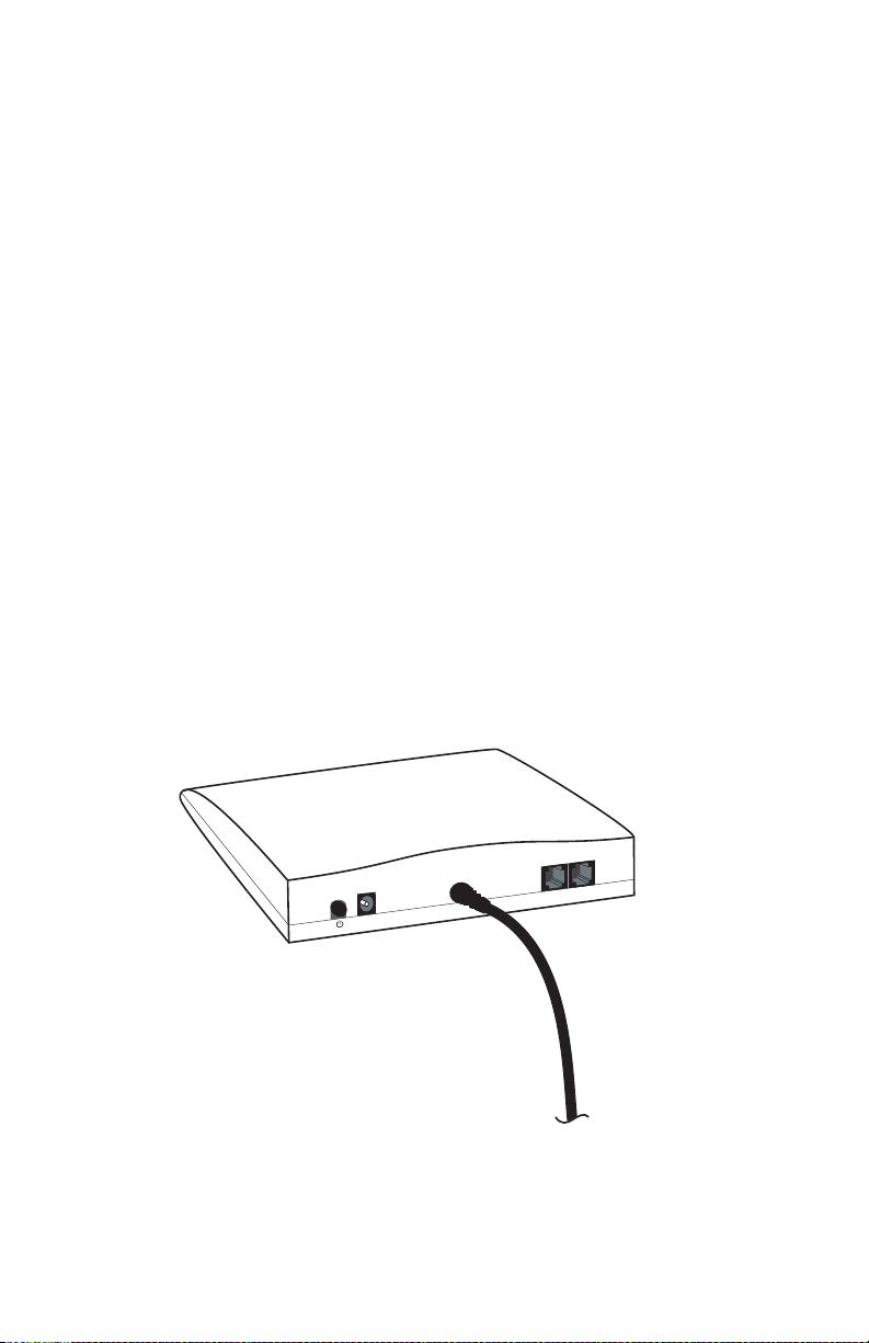
To connect the Modem:
1. Ensure the computer is powered down.
2. Plug the serial cable connected to the rear panel of the Modem in the serial
port on the computer.
3. Plug one end of the phone cable to the “Line” port on the rear panel of the
Modem, and the other end to the phone wall jack.
.
☞
Note:Ifconnecting the Modem in the United Kingdom, insert
the telephone adapter included with the Modem package
between the wall jack and phone cable.
4. Plug the cable connected to the telephone in the “Phone” port on the back of
the Modem.
5. Plug the power adapter into an electrical wall outlet, and plug the power cable
in the “Power” port on the back of the Modem.
The Modem is now connected. Next, install the driver software as explained in
“Installing the Software.”
)
2
Phone
Line
r
e
ow
P
Serial Cable
(to Serial Port
on computer
Page 9

6
Actiontec External 56K/V92 Modem User Manual
Power Switch
The Modem’s Power Switch is located on the left side of the rear panel, and is a
push-button type switch. Push the button to turn the Modem on, and push it
again to turn it off.
Front Panel
The front panel of the Modem contains a series of indicator LEDs (light emitting
diodes).
LEDs
PWR – When on, indicates the Modem is powered up.
RD – Receive Data; on when the Modem is receiving data.
TD – Transmit Data; on when the Modem is sending data.
OH – Off Hook; on when the Modem is off hook.
Page 10
7
Installing the
Software
After connecting the Modem to the computer and the phone line, the driver software must be loaded on the computer. Select the operating system used, and follow the instructions.
Windows 98 and 98 SE
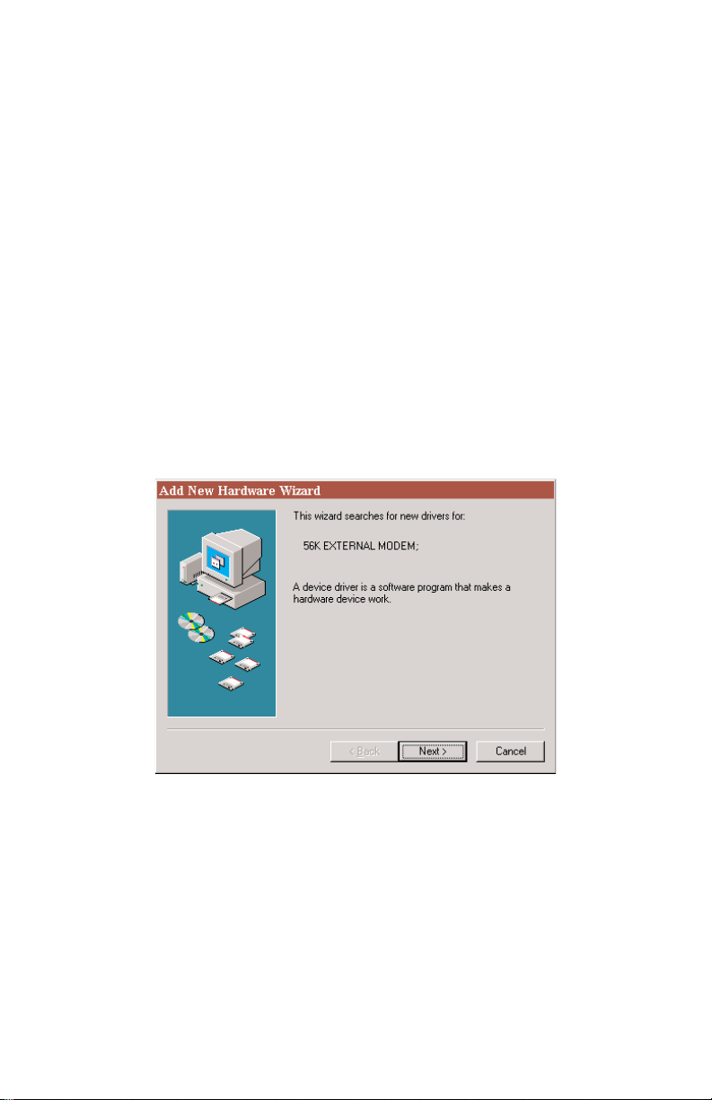
1. Ensure the Modem is turned off, then power up the computer and, while it is
booting, insert the Installation CD in the CD-ROM drive.
2. After the computer has booted, turn on the Modem.
3. The first “Add New Hardware Wizard” window appears. Click Next.
3
Page 11
8
Actiontec External 56K/V92 Modem User Manual
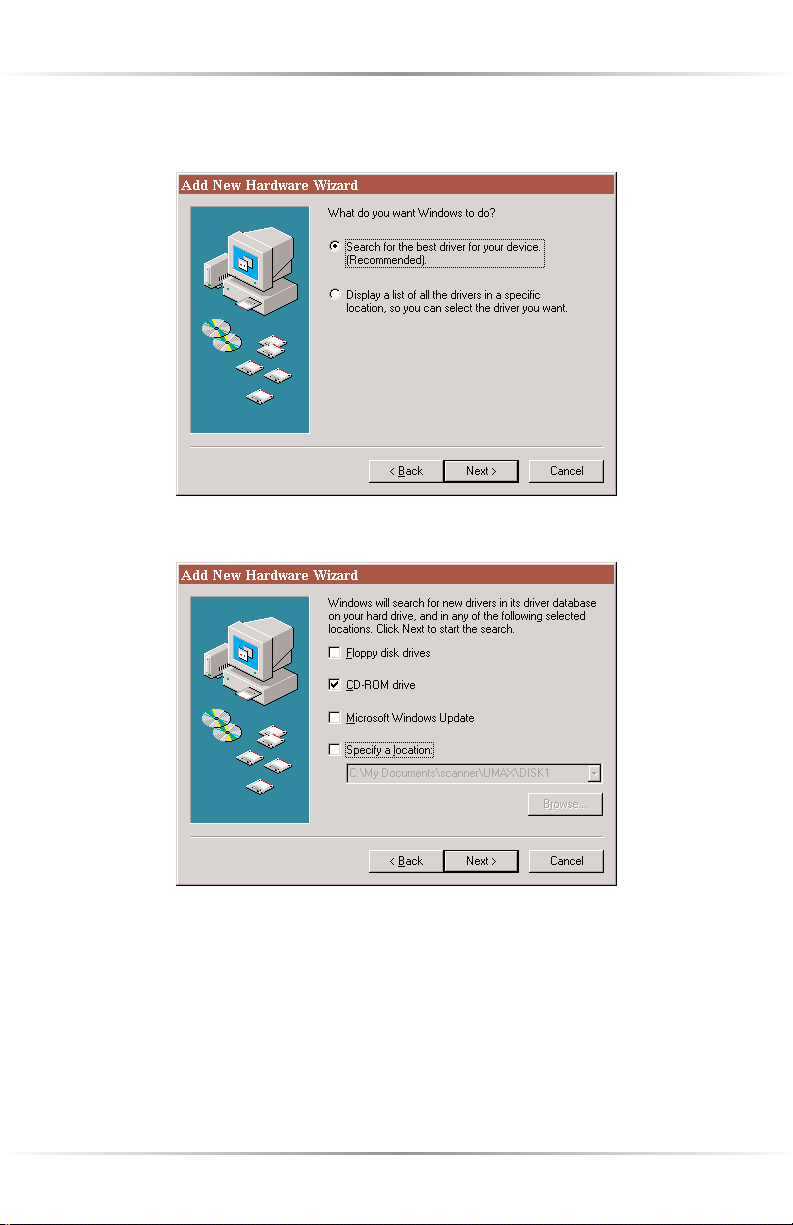
4. In the next window, select Search for the best driver for your device
(Recommended), then click Next.
5. When the next window appears, click CD-ROM drive, then click Next.
Page 12
9
Chapter 3 Installing the Software
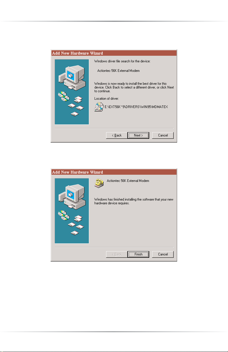
6. In the next window that appears, Windows searches for and then finds the
proper software on the Installation CD. Click Next.
7. The software is loaded on the hard drive of the computer. When the window,
below, appears, click Finish.
The Modem is now ready to use.To verify the driver software installation, see
“Verifying Driver Software Installation (Windows 98 and Me)” on page 13.
Page 13
10
Actiontec External 56K/V92 Modem User Manual
Windows Me
1. Ensure the Modem is turned off, then power up the computer and, while it is
booting, insert the Installation CD in the CD-ROM drive.
2. After the computer has booted, turn on the Modem.
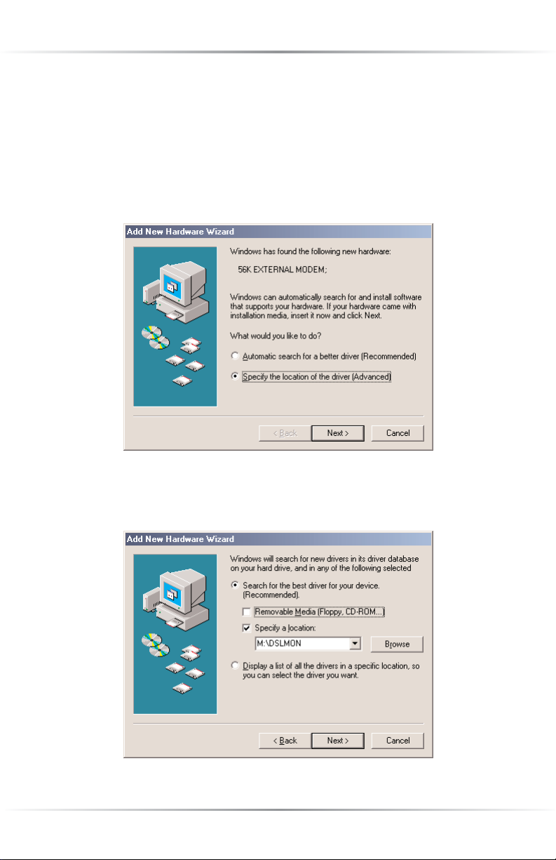
3. The first “Add New Hardware Wizard” window appears. Select the Specify the
location of the driver (Advanced) option, then click Next.
4. In the next “Add New Hardware Found” window, select Search for the best
driver for your device (Recommended).Then, select Specify a location and
click Browse.
Page 14

11
Chapter 3 Installing the Software
5. The “Browse for Folder” window appears. Click on the + next to “EXT
560_V181 [X:]” CD-ROM icon (where X is the drive letter of the CD-ROM
drive on the computer). Three folders appear underneath “EXT 560_V181
[X:].” Click on the + next to the “EXT 56KV92” folder icon. More folders
appear beneath “EXT 56KV92.” Click on the + next the “Drivers” folder. Select
the “WinMe” folder icon from the folders that appear below “Drivers” then
click OK.
6. The “Add New Hardware Wizard” window reappears, with the proper path to
the driver software appearing in the text box next to the “Browse” button.
Click Next.
Page 15

12
Actiontec External 56K/V92 Modem User Manual
7. In the next “Add New Hardware Wizard” window, click Next.
8. In the next window, Windows searches for and then finds the proper software
on the Installation CD. Click Next.
Page 16

13
Chapter 3 Installing the Software
9. The final “Add New Hardware Wizard” window appears. Click Finish to com-
plete the download.
The Modem is now ready to use.
Verifying Driver Software Installation (Windows 98 and Me)
To verify the Modem and its driver software are configured properly:
1. Select Start, Settings, then Control Panel.
2. In the “Control Panel” window, select Properties, then Diagnostics.
Page 17

14
Actiontec External 56K/V92 Modem User Manual
3. In the “Diagnostics” tab of the “Modem Properties” window, select the COM
port used by the Modem, then click More Info….
4. The “More Info” window appears, displaying the settings used by the Modem.
Click OK when finished.
.
☞
Note:The settings displayed in the “More Info” window shown
above may be different from the user’s settings.
Page 18

15
Chapter 3 Installing the Software
Windows NT 4.0
1. Ensure the Modem is turned off, then power up the computer and, while it is
booting, insert the Installation CD in the CD-ROM drive.
2. After the computer has booted, turn on the Modem.
3. From the desktop, select Start, Settings, then Control Panel.
4. In the “Control Panel” window, double-click Modems.The first “Install New
Modem” window appears. Ensure the check box is not checked, then click
Next.
5. In the next “Install New Modem” window, Windows detects the Modem.
When “Standard Modem” appears in the text box, click Change….
Page 19

16
Actiontec External 56K/V92 Modem User Manual
6. In the next window, click Have Disk…
7. In the “Install From Disk” window, navigate to the CD-ROM drive (either by
browsing using the Browse… button, or entering the drive letter of the CDROM drive in the “Copy manufacturer’s files from” text box), then click OK.
Page 20

17
Chapter 3 Installing the Software
8. The “Locate File” window appears. Select the CD-ROM drive icon from the
“Look in” drop down list.
9. The contents of the CD appear in the “Locate File” window. Select EXT
56KV92, then click Open.
Page 21

18
Actiontec External 56K/V92 Modem User Manual
10. The contents of the folder appear in the “Locate File” window. Select Drivers,
then click Open.
11. The contents of the “Drivers” folder appear in the “Locate File” window. Select
WinNT, then click Open.
Page 22

19
Chapter 3 Installing the Software
12. The contents of the “WinNT” folder appear in the “Locate File” window.
Select Mdmatex.inf, then click Open.
13. An “Install From Disk” window appears. Click OK.
Page 23

20
Actiontec External 56K/V92 Modem User Manual
14. In the next window, ensure Actiontec 56K External Modem is listed in the
“Models” list box, then click OK
15. Another window appears. Ensure Actiontec 56K External Modem is listed in
the text box, then click Next.
Page 24

21
Chapter 3 Installing the Software
16. A “Modem Setup” window appears, stating that the computer needs to be
restarted before the Modem can be used. Click OK.
17. After the computer has restarted, an “Install New Modem” window appears,
stating that the Modem has been set up successfully. Click Finish.
The Modem is now ready to use. To use the Modem to dial into a Windows NT
Remote Access server or connect to the Internet, configure “Dial Up Networking.”
For more details, see the Windows NT documentation.
Page 25

22
Actiontec External 56K/V92 Modem User Manual
Windows 2000
1. Ensure the Modem is turned off, then power up the computer and, while it is
booting, insert the Installation CD in the CD-ROM drive.
2. After the computer has booted, turn on the Modem.
3. The first “Found New Hardware Wizard” window appears. Click Next.
Page 26

23
Chapter 3 Installing the Software
4. In the next window, select Search for a suitable driver for my device (rec-
ommended), then click Next.
5. Another “Found New Hardware Wizard” window appears. Select CD-ROM
drives from the “Optional search locations” list, then click Next.
Page 27

24
Actiontec External 56K/V92 Modem User Manual
6. In the next window, Windows states it has found the driver. Click Next.
7.The final “Found New Hardware Wizard” window appears. Click Finish.The
driver software is now installed.
The Modem is now ready to use. To verify the driver software installation, see
“Verifying Driver Software Installation (Windows 2000 and XP)” on page 27.
Page 28

25
Chapter 3 Installing the Software
Windows XP
1. Ensure the Modem is turned off, then power up the computer and, while it is
booting, insert the Installation CD in the CD-ROM drive.
2. After the computer boots up, turn on the Modem.
3. The first “Hardware Update Wizard” window appears. Select Install from a
list, or specific location (Advanced), then click Next.
Page 29

26
Actiontec External 56K/V92 Modem User Manual
4. Another “Hardware Update Wizard” window appears. Select Search remov-
able media (floppy, CD-ROM…), then click Next.
5. When the “Found New Hardware Wizard” window appears, click Finish.The
driver software is now installed.
The Modem is now ready to use.
Page 30

27
Chapter 3 Installing the Software
Verifying Driver Software Installation (Windows 2000 and XP)
To verify the Modem and its driver software are configured properly:
1. Right-click My Computer, then select Properties.
2. In the “System Properties” window, select Hardware, then click Device
Manager….
3. In the “Device Manager” window, click the “+” next to “Modems,” then dou-
ble-click Actiontec V.92 External Modem.
Page 31

28
Actiontec External 56K/V92 Modem User Manual
4. When the “Actiontec V.92 External Modem Properties” window appears, select
Diagnostics, then click Query Modem.
5. The modem’s configuration information is displayed.
Page 32

29
Troubleshooting
This section describes a few problems that may be encountered when using the
Modem, and solutions to overcome them.
When I restart my computer, the Modem is
not detected.
Ensure the Modem is turned on, and the serial cable is connected properly to a
COM port on the computer, then restart the computer.
The Modem doesn’t dial.
Ensure the Modem is turned on and connected to a working phone line. To
ensure the phone line is functioning properly, plug a telephone into the phone
wall jack and listen for a dial tone.
The Modem dials but doesn’t connect.
First, verify the communications software is configured to the correct COM port
and IRQ setting. Second, ensure the phone line is working properly (plug a telephone into the phone wall jack and listen for a dial tone).
.
☞
Note:To determine the COM port and IRQ setting used by the
Modem, select Start, Settings, Control Panel, then double-click
Modems.Select Diagnostics, then More Info.
The Modem reports a busy signal.
First, verify the Modem is connected directly to a wall phone jack. If the Modem
is a connected to a phone via a splitter, it will not function properly. Second,
ensure the numerical prefix *70 is not included before the access number provided by the Internet Service Provider (ISP). The *70 prefix disables call waiting,
sending out a busy signal instead.
4
Page 33

30
Actiontec External 56K/V92 Modem User Manual
Page 34

31
AT Commands
To access the Modem manually, use AT commands. AT commands can be sent to
the Modem from a computer running a communications program.
Command Format
All commands must begin with the AT prefix, followed by the parameter, and ending by pressing the Enter key on the keyboard. All commands can be entered in
either all upper– or all lower–case, but not upper– and lower–case mixed together.
A command entered without any parameters automatically specifies the same command with a parameter of “0.” The maximum length of a command is eight (8)
characters. The Modem does not count the AT prefix, carriage returns, or spaces.
For example, entering the command
ATH
causes the modem to hang up.
Basic AT Commands
In the following lists, the commands are in bold text, followed by a short functional description. Default settings are noted with an asterisk (*).
A/ Repeat last command (do not precede this command with AT
or follow by pressing the Enter key)
A Answer
D_ Dial command
P Select pulse dialing (affects current and subsequent dialing)
T Select tone dialing (affects current and subsequent dialing)
En Command echo
E0 Disables echo
E1 Enables echo*
Hn Switch hook control
A
Page 35

32
Actiontec External 56K/V92 Modem User Manual
H0 Hangs up the telephone line*
H1 Picks up the telephone line
Ln Speaker volume
L0 Off or low speaker volume
L1 Low volume
L2 Medium volume*
L3 High volume
ITU–T V.90 Operation Commands
Three S-registers support K56flex, V.90, and V.34 connections. The S37 register is
used to control the upstream V.34 rate. The S38 register is used to control the maximum downstream speed at which the Modem attempts to connect. To disable V.90,
set S38 to 0.The S109 register is used to select between K56flex and V.90 protocols.
Dial Line Rate (S37)
S37 = 0 maximum modem speed*
S37 = 1 reserved
S37 = 2 1200 bits/s and 75 bits/s
S37 = 3 300 bits/s
S37 = 4 reserved
S37 = 5 1200 bits/s
S37 = 6 2400 bits/s
S37 = 7 4800 bits/s
S37 = 8 7200 bits/s
S37 = 9 9600 bits/s
S37 = 10 12000 bits/s
S37 = 11 14400 bits/s
Page 36

33
Chapter 4 Tr oubleshooting
S37 = 12 16800 bits/s
S37 = 13 19200 bits/s
S37 = 14 21600 bits/s
S37 = 15 24000 bits/s
S37 = 16 26400 bits/s
S37 = 17 28800 bits/s
S37 = 18 31200 bits/s
S37 = 19 33600 bits/s
56K Dial Line Rate (S38)
S38 = 0 Disable all 56K connections
S38 = 1 autorate (maximum achievable connection)*
S38 = 2 29333 bits/s
S38 = 3 30666 bits/s
S38 = 4 32000 bits/s
S38 = 5 33333 bits/s
S38 = 6 34666 bits/s
S38 = 7 36000 bits/s
S38 = 8 37333 bits/s
S38 = 9 38666 bits/s
S38 = 10 40000 bits/s
S38 = 12 42666 bits/s
S38 = 13 44000 bits/s
S38 = 14 45333 bits/s
S38 = 15 46666 bits/s
Page 37

34
Actiontec External 56K/V92 Modem User Manual
S38 = 16 48000 bits/s
S38 = 17 49333 bits/s
S38 = 18 50666 bits/s
S38 = 19 52000 bits/s
S38 = 20 53333 bits/s
K56flex and V.90 Selection (S109)
Use this register to disable 56K connections, or to select between K56flex and V.90
protocols. The default setting (S109=1) will attempt K56flex, and then V.34,
depending upon the central site modem being called and the condition of the
phone line.
S109 = 0 Disable all 56K connections
S109 = 1 K56flex only (V.90 disabled)*
S109 = 2 V. 90 only (K56flex disabled)
Command Examples
The following list contains a few AT Command examples.
at&fs38=0s109=0 – disables ALL 56K connections.
at&fs38=1s109=1s37=14 – disables V.90 connections. The Modem attempts to
connect at K56flex rates, with the V.34 upstream rate limited to 21.6K bps.
at&fs38=1s109=2 – causes the Modem to attempt a V.90 connection only. If
V.90 is not achieved, it will fall back to V.34 rates.
at&fs38=10s109=2 – causes the Modem to attempt a V.90 connection at 40K
bps. It will fall back to slower speeds if it cannot achieve or maintain this rate.
As a suggested “init string” in the communications program, use:
at&fw2s109=2s38=1s37=14
Page 38

35
Notices
Regulatory Compliance Notices
Class B Equipment
This equipment has been tested and found to comply with the limits for a Class B
digital device, pursuant to Part 15 of the FCC Rules. These limits are designed to
provide reasonable protection against harmful interference in a residential installation. This equipment generates, uses, and can radiate radio frequency energy and,
if not installed and used in accordance with the instructions, may cause harmful
interference to radio communications. However, there is no guarantee that interference will not occur in a particular installation. If this equipment does cause
harmful interference to radio or television reception, which can be determined by
turning the equipment off and on, the user is encouraged to try to correct the
interference by implementing one or more of the following measures:
Reorient or relocate the receiving antenna;
Increase the separation between the equipment and receiver;
Connect the equipment to an outlet on a circuit different from that to
which the receiver is connected;
Consult the dealer or an experienced radio or television technician for help.
Page 39

36
Actiontec External 56K/V92 Modem User Manual
Modifications
The
FCC requires the user to be notified that any changes or modifications made
to this device that are not expressly approved by Actiontec Electronics, Inc., may
void the user’s authority to operate the equipment.
Declaration of conformity for products marked with the
FCC logo – United States
only.
This device complies with Part 15 of the FCC Rules. Operation is subject to the fol-
lowing two conditions:
1.This device may not cause harmful interference;
2. This device must accept any interference received, including interference that
may cause undesired operation.
☞
Note:To comply with FCC RF exposure compliance require-
ments, the antenna used for this transmitter must be installed to
provide a separation distance of at least 20 cm from all persons
and must not be co-located or operating in conjunction with
any other antenna or transmitter.
For questions regarding your product or the FCC declaration, contact:
Actiontec Electronics, Inc.
760 N. Mary Ave.
Sunnyvale, CA 94086
United States
Te l : 408.752.7700
Fax: 408.541.9005
Page 40

37
Limited Warranty
Hardware: Act iontec Electronics, Inc., warrants to the end user (“Customer”) that
this hardware product will be free from defects in workmanship and materials,
under normal use and service, for twelve (12) months from the date of purchase
from Actiontec Electronics or its authorized reseller.
Actiontec Electronics’ sole obligation under this express warranty shall be, at
Actiontec’s option and expense, to repair the defective product or part, deliver to
Customer an equivalent product or part to replace the defective item, or if neither
of the two foregoing options is reasonably available, Actiontec Electronics may, in its
sole discretion, refund to Customer the purchase price paid for the defective product. All products that are replaced will become the property of Act iontec Electronics,
Inc. Replacement products may be new or reconditioned. Actiontec Electronics war-
rants any replaced or repaired product or part for ninety (90) days from shipment,
or the remainder of the initial warranty period, whichever is longer.
Software: Actiontec Electronics warrants to Customer that each software program
licensed from it will perform in substantial conformance to its program specifications, for a period of ninety (90) days from the date of purchase from Actiontec
Electronics or its authorized reseller. Act iontec Electronics warrants the media con-
taining software against failure during the warranty period. The only updates that
will be provided are at the sole discretion of Actiontec Electronics and will only be
available for download at the Act iontec Web site, www.actiontec.com. Actiontec
Electronics’ sole obligation under this express warranty shall be, at Actiontec
Electronics’ option and expense, to refund the purchase price paid by Customer for
any defective software product, or to replace any defective media with software which
substantially conforms to applicable Actiontec Electronics published specifications.
Customer assumes responsibility for the selection of the appropriate applications
program and associated reference materials. Actiontec Electronics makes no warranty
or representation that its software products will meet Customer’s requirements or
work in combination with any hardware or applications software products provided
by third parties, that the operation of the software products will be uninterrupted or
error free, or that all defects in the software products will be corrected. For any thirdparty products listed in the Action tec Electronics software product documentation or
specifications as being compatible, Actiontec Electronics will make reasonable efforts
to provide compatibility, except where the non-compatibility is caused by a “bug”or
defect in the third party’s product or from use of the software product not in accordance with Actiontec Electronics published specifications or user guide.
Page 41

38
Actiontec External 56K/V92 Modem User Manual
THIS ACTIONTEC ELECTRONICS PRODUCT MAY INCLUDE OR BE BUNDLED
WITH THIRD-PARTY SOFTWARE, THE USE OF WHICH IS GOVERNED BY A SEPA-
RATE END-USER LICENSE AGREEMENT.
THIS ACTIONTEC ELECTRONICS WARRANTY DOES NOT APPLY TO SUCH THIRD-
PA RTY SOFTWARE. FOR THE APPLICABLE WARRANTY, PLEASE REFER TO THE
END-USER LICENSE AGREEMENT GOVERNING THE USE OF SUCH SOFTWARE.
Obtaining Warranty Service:Customer may contact Actiontec Electronics Technical
Support Center within the applicable warranty period to obtain warranty service
authorization. Dated proof of purchase from Acti ontec Electronics or its authorized
reseller may be required. Products returned to Actiontec Electronics must be pre-
authorized by Actiontec Electronics with a Return Merchandise Authorization
(RMA) number marked on the outside of the package, and sent prepaid and packaged appropriately for safe shipment, and it is recommended that they be insured or
sent by a method that provides for tracking of the package. The repaired or replaced
item will be shipped to Customer, at Action tec Electronics’ expense, not later than
thirty (30) days after Actiontec Electronics receives the defective product.
Return the product to:
(In the United States)
Actiontec Electronics, Inc.
760 North Mary Avenue
Sunnyvale, CA 94085
Actiontec Electronics shall not be responsible for any software, firmware, information,
memory data, or Customer data contained in, stored on, or integrated with any products returned to Actiontec Electronics for repair, whether under warranty or not.
WARRANTIES EXCLUSIVE: IF AN ACTIONTEC ELECTRONICS’ PRODUCT DOES
NOT OPERATE AS WARRANTED ABOVE, CUSTOMER’S SOLE REMEDY FOR
BREACH OF THAT WARRANTY SHALL BE REPAIR, REPLACEMENT, OR REFUND OF
THE PURCHASE PRICE PAID, AT ACTIONTEC ELECTRONICS’ OPTION. TO THE
FULL EXTENT ALLOWED BY LAW, THE FOREGOING WARRANTIES AND REME-
DIES ARE EXCLUSIVE AND IN LIEU OF ALL OTHER WARRANTIES, TERMS OR
CONDITIONS, EXPRESS OR IMPLIED, EITHER IN FACT OR BY OPERATION OF
LAW, STATUTORY OR OTHERWISE, INCLUDING WARRANTIES, TERMS OR CONDI-
TIONS OF MERCHANTABILITY, FITNESS FOR A PARTICULAR PURPOSE, SATISFAC-
TORY QUALITY, CORRESPONDENCE WITH DESCRIPTION, AND NON-INFRINGE-
MENT, ALL OF WHICH ARE EXPRESSLY DISCLAIMED. ACTIONTEC ELECTRONICS
Page 42

39
Limited Warranty
NEITHER ASSUMES NOR AUTHORIZES ANY OTHER PERSON TO ASSUME FOR IT
ANY OTHER LIABILITY IN CONNECTION WITH THE SALE, INSTALLATION, MAIN-
TENANCE OR USE OF ITS PRODUCTS.
ACTIONTEC ELECTRONICS SHALL NOT BE LIABLE UNDER THIS WARRANTY IF
ITS TESTING AND EXAMINATION DISCLOSE THAT THE ALLEGED DEFECT OR
MALFUNCTION IN THE PRODUCT DOES NOT EXIST OR WAS CAUSED BY CUS-
TOMER’S OR ANY THIRD PERSON’S MISUSE, NEGLECT, IMPROPER INSTALLATION
OR TESTING, UNAUTHORIZED ATTEMPT TO OPEN, REPAIR OR MODIFY THE
PRODUCT, OR ANY OTHER CAUSE BEYOND THE RANGE OF THE INTENDED USE,
OR BY ACCIDENT, FIRE, LIGHTNING, OTHER HAZARDS, OR ACTS OF GOD.
LIMITATION OF LIABILITY:TO THE FULL EXTENT ALLOWED BY LAW, ACTIONTEC
ELECTRONICS ALSO EXCLUDES FOR ITSELF AND ITS SUPPLIERS ANY LIABILITY,
WHETHER BASED IN CONTRACT OR TORT (INCLUDING NEGLIGENCE), FOR
INCIDENTAL, CONSEQUENTIAL, INDIRECT, SPECIAL, OR PUNITIVE DAMAGES OF
ANY KIND, OR FOR LOSS OF REVENUE OR PROFITS, LOSS OF BUSINESS, LOSS OF
INFORMATION OR DATA, OR OTHER FINANCIAL LOSS ARISING OUT OF OR IN
CONNECTION WITH THE SALE, INSTALLATION, MAINTENANCE, USE, PERFOR-
MANCE, FAILURE, OR INTERRUPTION OF ITS PRODUCT, EVEN IF ACTIONTEC
ELECTRONICS OR ITS AUTHORIZED RESELLER HAS BEEN ADVISED OF THE POSSI-
BILITY OF SUCH DAMAGES, AND LIMITS ITS LIABILITY TO REPAIR, REPLACE-
MENT,OR REFUND OF THE PURCHASE PRICE PAID, AT ACTIONTEC ELECTRONICS’
OPTION. THIS DISCLAIMER OF LIABILITY FOR DAMAGES WILL NOT BE AFFECTED
IF ANY REMEDY PROVIDED HEREIN SHALL FAIL OF ITS ESSENTIAL PURPOSE.
Disclaimer:Some countries, states or provinces do not allow the exclusion or limitation of implied warranties or the limitation of incidental or consequential damages for certain products supplied to consumers, or the limitation of liability for
personal injury, so the above limitations and exclusions may be limited in their
application to you. When the implied warranties are not allowed to be excluded in
their entirety, they will be limited to the duration of the applicable written warranty.
This warranty gives you specific legal rights which may vary depending on local law.
Dispute Resolution:The customer may contact the Director of Technical Support
in the event the Customer is not satisfied with Actiontec Electronics’ response to
the complaint. In the event that the Customer is still not satisfied with the response
of the Director of Technical Support, the Customer is instructed to contact the
Director of Marketing. In the event that the Customer is still not satisfied with the
response of the Director of Marketing, the Customer is instructed to contact the
Chief Financial Officer and/or President.
Page 43

40
Actiontec External 56K/V92 Modem User Manual
Governing Law:This Limited Warranty shall be governed by the laws of the State
of California, U.S.A., excluding its conflicts of laws and principles, and excluding
the United Nations Convention on Contracts for the International Sale of Goods.
 Loading...