

Page 1

56K V.90 PCI Voice/Fax
Windows Modem
Page 2

Table of Contents
Proprietary Notice and Disclaimer .................................................................1
Introduction.......................................................................................................
Contacting Actiontec Customer Support ..................................................
Do This First ......................................................................................................
For Windows 95 and Windows 98 Installations ............................................. 3
For Windows NT 4.0 Installation ....................................................................4
For Windows 2000 Professional Installation..................................................5
Installing The Modem......................................................................................
Hardware Installation..................................................................................... 6
Connecting Devices to the Modem................................................................8
Configuring Windows 95................................................................................9
Configuring Windows 95B ...........................................................................11
Configuring Windows 98..............................................................................13
Configuring Windows NT 4.0 .......................................................................18
Configuring Windows 2000 Professional.....................................................22
Installing Communications Software .......................................................
The Modem’s Voice Features ......................................................................2 9
Troubleshooting .............................................................................................
Windows 95/95B/98.....................................................................................31
Windows NT 4.0 ..........................................................................................34
Common Problems ......................................................................................3 5
Uninstalling the Modem ...............................................................................3 7
AT Command Set ...........................................................................................
AT Commands .............................................................................................40
AT Commands for Testing and Debugging ..................................................64
S-Registers Reference ................................................................................67
Notices..............................................................................................................
9
2
3
6
29
31
40
77
Proprietary Notice and Disclaimer
Unless otherwise noted, this document and the information herein disclosed are proprietary to Action-
tec Electronics, Inc. Any person or entity to whom this document is furnished or who otherwise has
possession thereof, by acceptance agrees that it will not be copied or reproduced in whole or in part,
nor used in any manner except to meet the purposes for which it was delivered.
The information in this document is subject to change without notice and should not be construed as
a commitment by Actiontec. Although Actiontec will make every effort to inform users of substantive
errors, Actiontec disclaims all liability for any loss or damage resulting from the use of this document or
any hardware or software described herein, including without limitation contingent, special or incidental liability.
Note: PC is a trademark of IBM Corporation. Windows 95 and Windows NT are trademarks of Microsoft, Inc. K56flex is a trademark
of Lucent Technologies, Inc. and Rockwell International
1
Page 3

Introduction
Thank you for purchasing the Actiontec PCI Pro 56K internal modem. The PCI P ro
incorporates the latest technology in controller-less V.90 modems for the PCI bus.
This technology improves the performance and capabilities of personal computer
fax/modems. The use of the PCI Bus frees the user from having to use an ISA slot
which is most likely already being used by another peripheral. Almost every PC has
at least one free PCI slot.
Host-based or “Windows” modems utilize your computer’s internal Central P rocessing Unit, or CPU to perform some of their functions. The modem’s onboar d digital
signal processing circuitry handles the most processor-intensive functions such as
V.90 and V.34 modulation, while the CPU handles more routine communications
tasks like data compression. This allows for fewer parts and greater reliability without
taxing the overall system speed. It also allows the modem greater access to memory
and disk storage space. As personal computers advance in speed and capabilities,
controller-less modems can take advantage of these improvements. Simply download
the new driver, follow the installation instructions, and reboot your system. In this
way, the performance of your modem improves as your PC hardware improves.
Contacting
Actiontec Electronics prides itself on making high-quality , durable, high-performance
products. If you should need assistance, the Actiontec T echnical Support Department
is available from 7:00 AM to 7:00 PM Pacific Coast Time, Monday through Friday
to provide professional support.
Actiontec Electronics, Inc.
Technical Support
760 N. Mary Avenue
Sunnyvale, CA 94086
Phone: 408-752-7714 (choose option 7)
Fax: 408-732-0097
BBS: 408-732-0112
Email:techsupp@actiontec.com
New drivers are released as need arises to insure maximum compatibility and operation of your new Actiontec PCI Pro 56K internal modem. Find out about these and
other new Actiontec products at the Actiontec web site:
Action
http://www.actiontec.com
tec Customer Support
2
Page 4
Do This First
Please read the following tips carefully before attempting to install your new modem.
For Windows 95 and Windows 98 Installations
Be sure to remove all other modem drivers from your operating system. To do this,
right-click M y Computer, choose P roperties from the menu that appears, then click
on the Device Manager tab. Double-click the Modems icon in the list of devices to
show the modems installed. Click once on the icon next to any modems in this list to
select them. When all of the modems are selected, click Remove.
T urn off the computer and physically r emove your old modem from the system. Once
you remove the old modem and its drivers from your system, you will need the old modem
driver diskette if you wish to reinstall it at a later date.
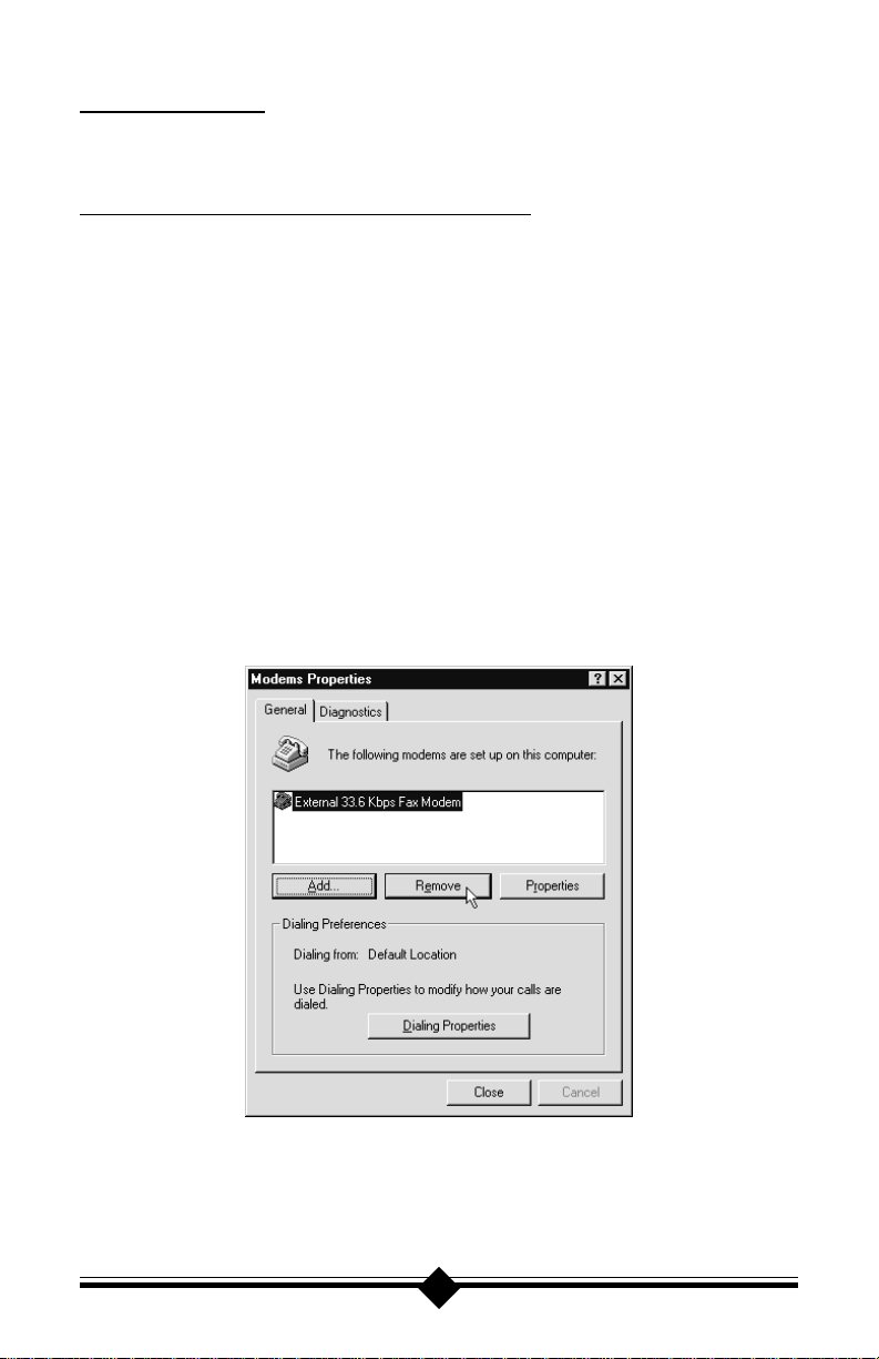
Restart the computer. On the taskbar, click S tart. On the Start menu, click Settings,
then click Control Panel. Double-click on the M odems icon. Select any and all listed
modems and click Remove. Shut down (rather than restart) the computer. Wait 5
seconds before turning it back on.
Figure 1: Windows 95/98 Modems Properties P anel
3
Page 5

If you are going to use the Telephone Answering Machine (TAM) functions of the
modem and you are running Windows 95, you need to install a software component
called Unimodem V. If you have Windows 95 OEM Service Release 2 (Version
4.00.950 B, hereafter referred to in this manual as Windows 95B) or a later version
of Windows, this component comes standard as part of the operating system.
To find out which version of Windows 95 you are using, right-click the My Com-
puter icon on the desktop, and choose Properties from the menu that appears. If the
version of Windows 95 is 4.00.950 or 4.00.950A, go to the UNIMODEM directory
of the CD-ROM that came with your modem and right-click on the UNIMOD V .INF
icon, (this may be named UNIMODV) then click on Install.. Restart your computer
to enable the drivers.
In order to support older software, the modem will always be assigned to COM 4.
This port assignment is made by Windows based on instructions contained in the
.INF file supplied with the modem. Check Device Manager and verify that COM 4
is not listed.
Right-click on the My Computer icon, choose Properties, and select the Device
Manager tab. From the device tree, double-click the Ports [COM & LPT] icon to
expand the list of ports. COM 1 and COM 2 should be listed. If COM 4 is listed, it
is in use, it must be made available as the modem will be automatically assigned to
this port. Highlight COM 4 by clicking once on its listing in device manager, then
click Remove. Click Refresh. If the COM 4 listing returns, you have a hardware
device using the port. Reinstall the device on another COM port.
For Windows NT 4.0 Installation
Before installing your new modem, be sure to remove any modems and their drivers
from your operating system. On the taskbar, click Start. On the Start menu click
Settings, then click Control Panel. Double-click the Modems icon. Highlight the
modem you wish to remove and click Remove. Turn off the computer and physically
remove the old modem. Do not install your new modem at this time. Follow the
procedures below to help insure a trouble-free installation. Once you remove the old
modem and its drivers from your system, you will need the old modem driver diskette if
you wish to reinstall it at a later date.
Determine that your installation of NT 4.0 is current. Service Pack 3 (or greater),
from Microsoft, should be installed. On the Start menu, click Settings then click
Administrative Tools then click Windows NT Diagnostics. Select the V ersion folder .
Service Pack 3 (or greater) should be stated. If you do not have the latest service pack
upgrade installed, it must be obtained from Microsoft. The latest upgrade can be
downloaded from the Microsoft web site: www.microsoft.com.
4
Page 6

For Windows 2000 Professional Installation
Important
Once you remove an old modem and its drivers from your system, you will need
the old modem’s driver diskette if you wish to reinstall it at a later date.
Before installing your new modem, be sure to remove any modems and their drivers
from your operating system. On the taskbar, click Start. On the Start menu click
Settings, then click Control Panel. Double-click the Phone and Modem Options
icon. Click the Modems tab to bring it to the front. Highlight the modem you wish
to remove and click Remove. Repeat this process for as many modems as you would
like to remove. Turn off the computer and physically remove the old modem. Do not
install your new modem at this time. Read and use the installation procedures that
follow.
5
Page 7
Installing The Modem
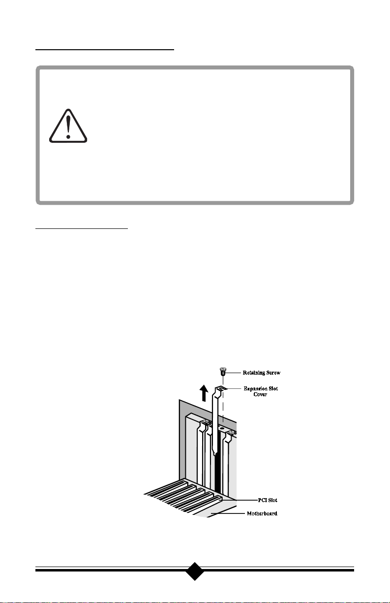
Always discharge static electricity before handling your modem. You
may discharge static electricity by touching a grounded metal structure
or by using any commercially available grounding strap.
Make sure the expansion slot type is 16-bit, which has two slots to fit
the ISA card. 8-bit slots have only one connector. If you use an 8-bit
slot, the modem will not have access to the higher interrupts (IRQ 9-
12).
The position of the expansion slots in your computer may differ from
the illustration shown but the installation procedure should be the same.
Hardware Installation
1. Turn off the computer and all peripheral devices connected to it.
2. Unplug the computer power cord from the wall receptacle.
3. Remove the computer’s cover. Refer to your computer owner’s manual for instructions.
4. Remove the screw securing the expansion slot cover behind one of the computer ’ s
available PCI expansion slots. Lift the expansion slot cover out as shown below.
Figure 2: Removing the Bac kplate
6
Page 8
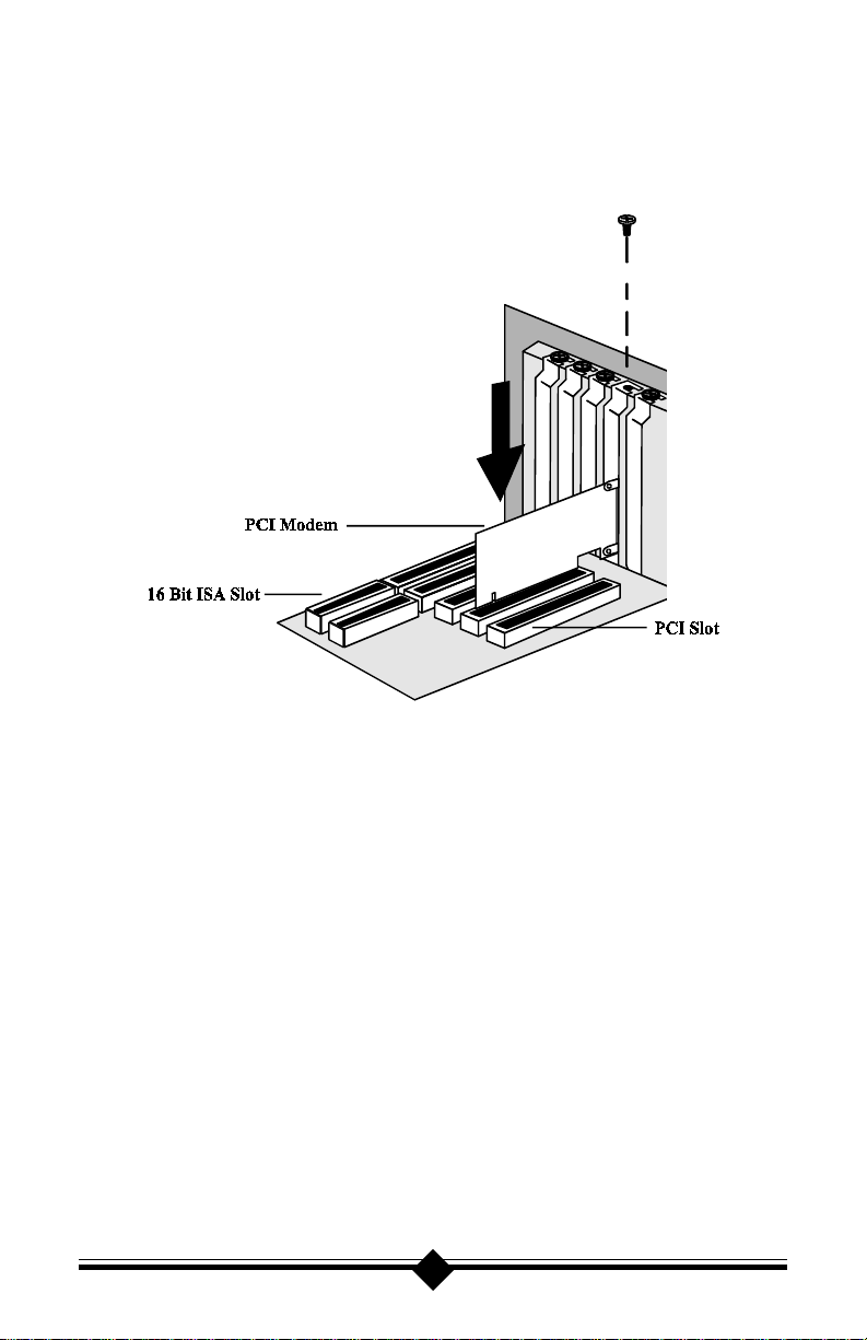
5. Firmly but gently insert the modem into the available PCI expansion slot. Ensure that the card is seated properly before securing it with the screw removed in
Step 4, as shown in the following diagram:
Figure 3: Installing The Modem
6. Put the chassis cover back on the computer.
7. Be sure that all power switches are in the OFF position, then reconnect the
power cables to the computer and its peripherals.
8. Connect the telephone line cable to the Line (Telco) jack as shown in Figure 7.
9. Turn on the computer and proceed to the following sections to configure your
modem to the operating system you are using.
7
Page 9

Connecting Devices to the Modem
Figure 4: Connecting Devices
On the rear panel of your modem are input jacks to connect devices to the modem.
As shown in the diagram, there are jacks for connection to a “ phone ” and to a phone
“line.” The connector labeled Line (Telco) is meant to be connected to a standard
analog phone line. To help reduce the load on your phone line, it is recommended
that the modem be the only device connected. You should remove all other devices
from your telephone line while the modem is in use.
8
Page 10
Configuring Windows 95
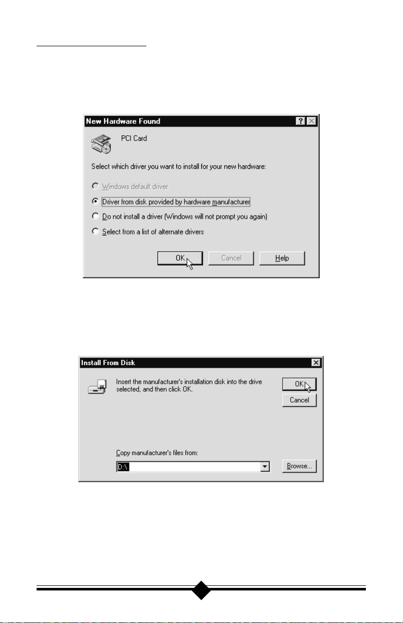
Step 1 Upon startup Windows 95 detects the modem and displays the New Hard-
ware Found dialog box. Click “D river from disk provided by hardware manu-
facturer” to select it, then click OK.
Step 2 If Windows asks for an installation disk, insert the modem’s installation
CD-ROM, and wait ten seconds so that windows can r ecognize the CD has
been inserted. Type the drive letter of your CD-ROM drive in the dialog
box that appears, and click OK.
9
Page 11
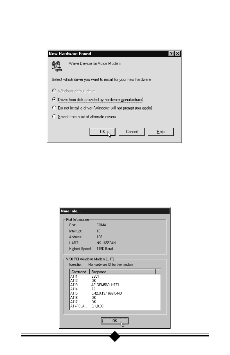
Step 3 After the installer has copied the .INF files to the hard disk, another New
Hardware Found dialog box will appear prompting for the “Wave Device
for Voice Modem”. Click OK. (See “Do This First” for information on
UNIMODEM.INF if the following screen does not appear.)
Step 4 Click OK to copy the Wave Device .INF file from the CD-ROM Drive.
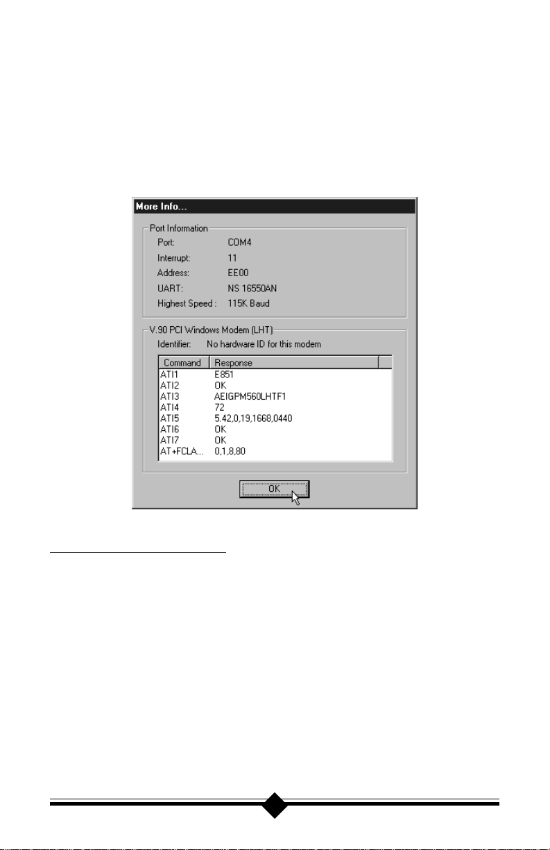
Step 5 T o determine what COM port and IR Q is assigned to the modem in Win-
dows 95, click on the Modems icon in Control P anel and select the Diag-
nostic tab. Click the COM port icon next to the modem and then click
More Info to view the modem properties. Take note of the COM port and
IRQ—these will be needed when you configure your communications software.
10
Page 12
Configuring Windows 95B
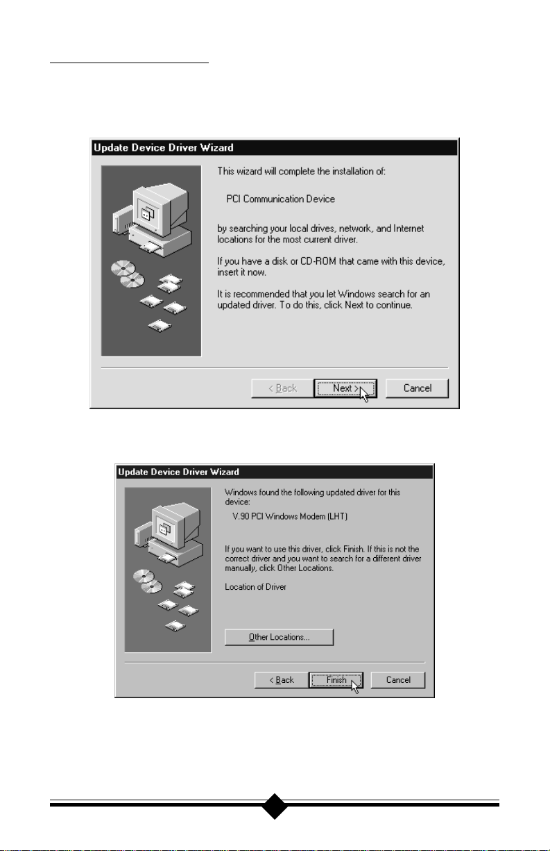
Step 1 Upon startup, Windows 95 detects the modem and launches the Update
Device Driver Wizard dialog box. Insert the modem’s installaiton CD-
ROM, wait ten seconds so that the CD can be read, then click Next.
Step 2 After Windows 95 has found the updated drivers for your modem, click
Finish.
Step 3 If Windows asks for an installation disk, click OK and type the drive letter
of your CD-ROM drive in the dialog box that appears and click OK.
Step 4 After the Wizard has copied the .INF files to the hard disk, it should detect
“Wave Device for Voice Modem” and prompt for its driver. Click N ext.
11
Page 13
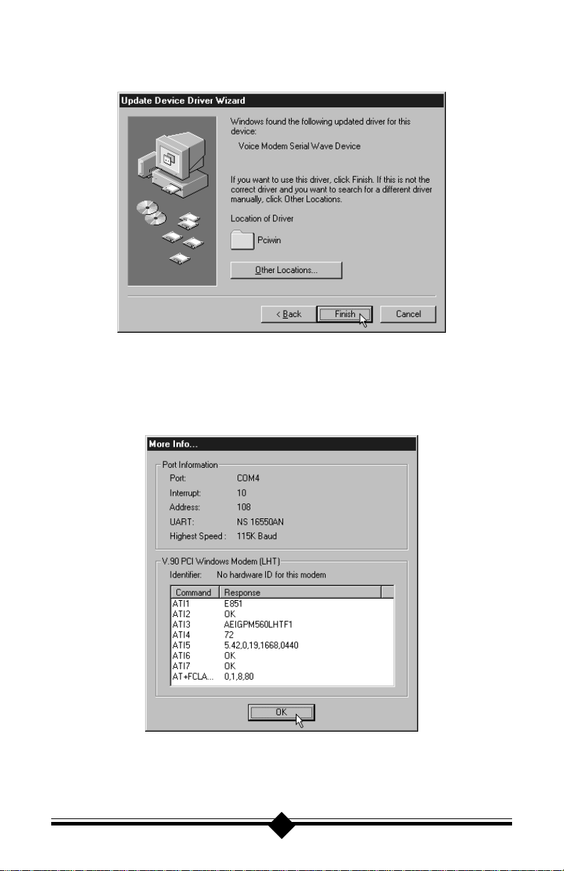
Step 5 Click Finish to copy the Wave Device .INF file from the CD-ROM drive.
Step 6 T o determine what COM port and IR Q is assigned to the modem in Win-
dows 95, click on the Modems icon in Control P anel and select the Diag-
nostics tab. Click on the COM port icon next to your modem and then
click More Info to view detailed diagnostic information.
Step 7 Remember this COM port number. Y ou may need this information to con-
figure your communications software.
12
Page 14
Configuring Windows 98
Step 1 After you have installed the modem hardware in your computer, turn on
the power and allow the system to boot normally.
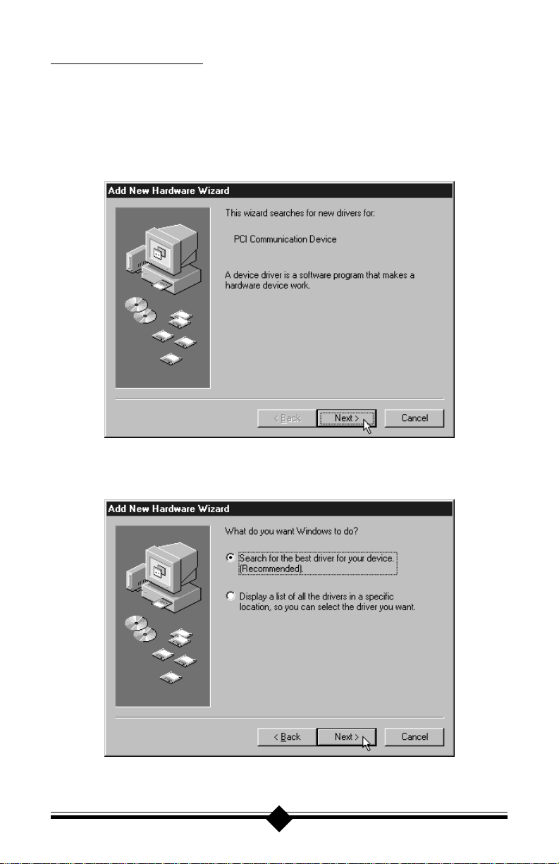
Step 2 Windows 98 will immediately display the Add New Hardware Wizar d and
identify the modem as a “PCI Communications Device”. Click the Next
button.
Step 3 At the next dialog box, make sure that “Search for the best driver for your
device. (Recommended)” is selected, and then click Next.
13
Page 15
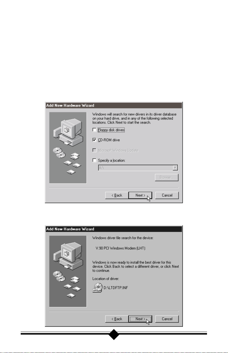
Step 4 Next the wizard will ask which drives or folders it should search for the
drivers. Click to select the CD-ROM drive. A check mark will appear in the
appropriate box. Make sure that all the other options are deselected, clicking them to deselect, if necessary. I nsert the modem ’ s installation CD-R OM.
Wait about 10 seconds, so that the CD-ROM drive can read the disc, and
click Next.
Note: After inserting the CD-ROM, make sure to wait a few seconds before click-
ing Next. Otherwise, the Wizard may report that it was unable to find the
drivers. If this is the case, click Back and then click Next, repeating this
process until the CD-ROM drive has read the CD-R OM and Windows has
found the drivers, displaying the dialog box shown in step 5.
Step 5 The Wizard will find the correct driver on the CD-ROM and identify the
modem as “V.90 PCI Windows Modem (LHT)”. Click Next.
14
Page 16
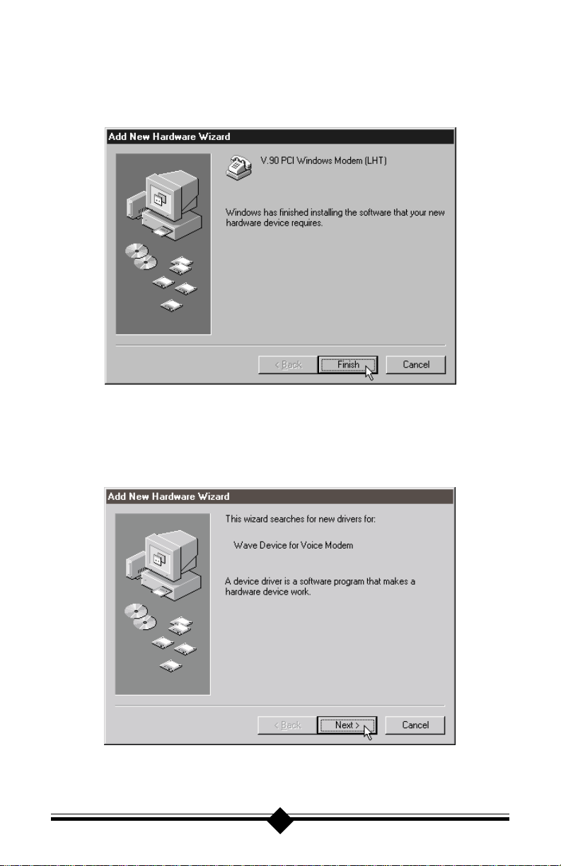
Step 6 After Windows has finished copying the drivers to where they belong in
your system, it will announce the end of the installation process. Click the
Finish button.
Step 7 The Wizard will now search for drivers for the Telephone Answering Func-
tions (TAM), also known as the “Wave Device for Voice Modem”. Click
Next.
15
Page 17
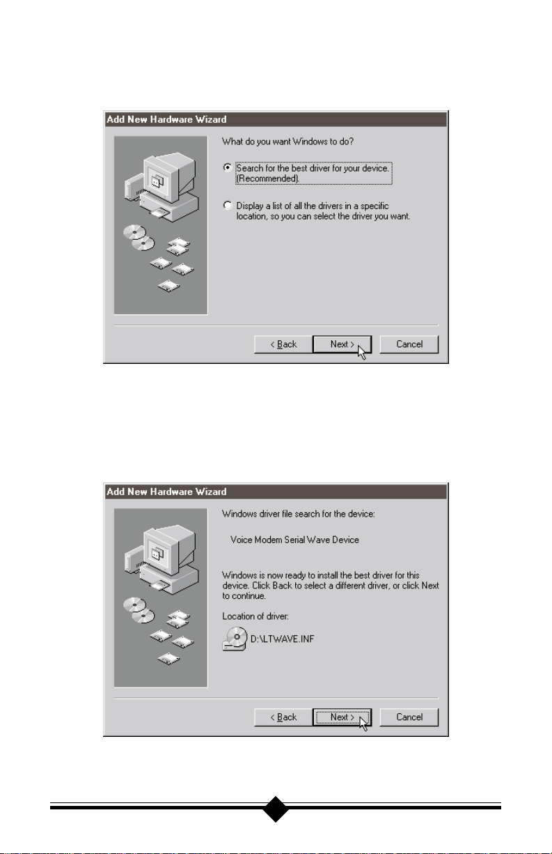
Step 8 At the next dialog box, make sure that “Search for the best driver for your
device. (Recommended)” is selected, and then click Next.
Step 9 Next the wizard will ask which drives or folders it should search for the
drivers. Click to select CD-ROM drive. A check mark will appear in the
appropriate box. Make sure that all the other options are deselected, clicking them to deselect, if necessary.
16
Page 18
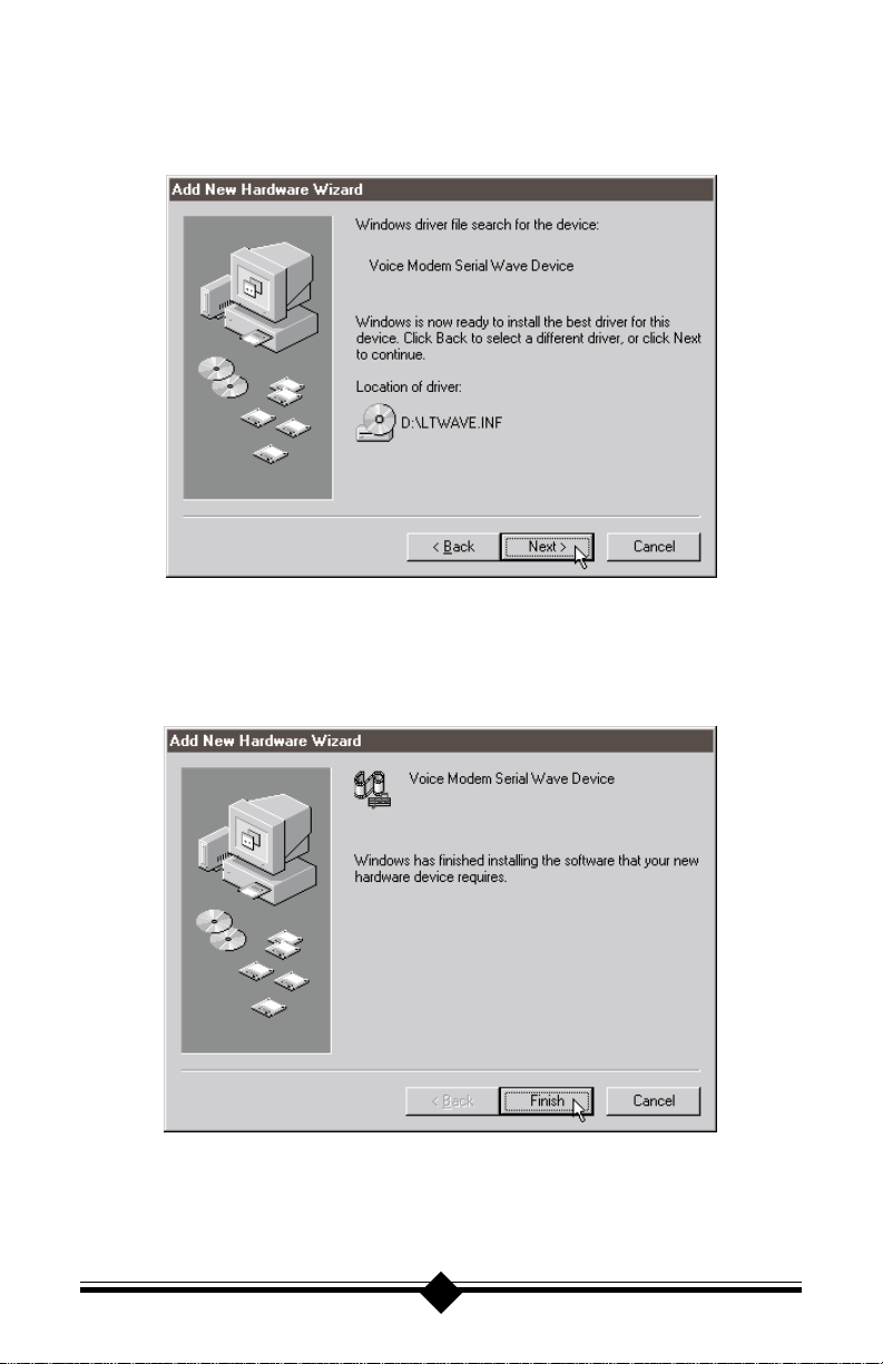
Step 10 The wizard will find the correct driver on the CD-ROM and announce it is
ready to install. Click Next.
Step 11 After Windows has finished copying the drivers to where they belong in
your system, it will announce the end of the installation process. Click the
Finish button.
17
Page 19
Step 12 Next, find out if the modem has been properly installed and configured for
use with your operating system. On the task bar, click Start. On the Start
menu, click Settings, then click Control Panels, then click Modems. Click
the Diagnostics tab. Click on the COM port icon next to the modem to
select it, then click More Info. Windows will communicate with the modem for a few seconds, and then report back with the information shown
below. (The COM port being used may vary.)
Configuring Windows NT 4.0
Step 1 Install your modem into an available PCI slot. (See “Do This First” for
important pre-installation information.)
Step 2 Insert your modem’ s installation CD-R OM into your computer’s CD-ROM
Drive.
Step 3 On the Start menu, click Programs, then click Windows Explorer. Navi-
gate to your CD-ROM drive. Double-click the drivers folder , then doubleclick the Pciwin folder . In the window that appears, double-click setup.exe.
18
Page 20
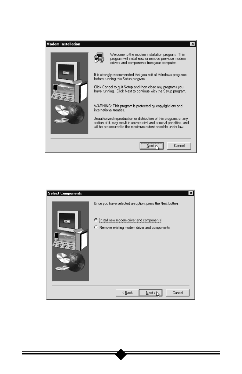
Step 4 The installation utility will show a welcome panel. Click Next.
Step 5 The next step in the installation process offers an install or remove option.
Select Install new modem drivers and components. Click Next.
19
Page 21
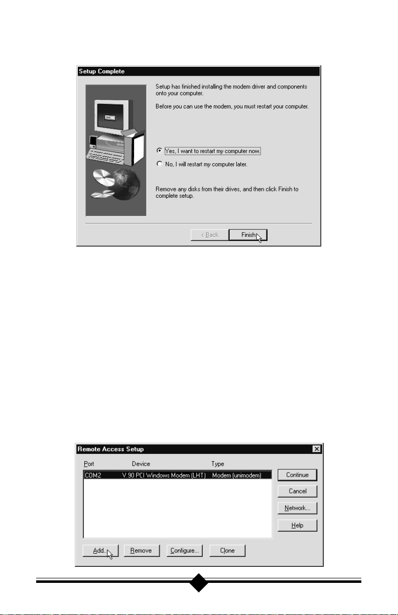
Step 6 After the installation utility has finished installing the drivers, restart your
computer to enable the drivers.
Step 7 Click on the Modems icon in the Control Panel. Verify that Windows NT
has correctly found the modem.
Step 8 If you wish to dial into a Windows NT Remote Access Server or wish to
connect to the Internet, you will need to configure Dial-up Networking. In
Control Panel double-click the N etwork icon. Click on the Services folder
and select Remote Access Service. If the Remote Access Service option is
not listed click on the Add button. Scroll-down the menu and select Re-
mote Access Service. Click the OK button. Windows NT may ask for its
CD-ROM for some files. Insert as required. After you have installed Remote Access Service add the appropriate protocols as directed (e.g. T CP/IP
for Internet Access).
Step 9 At the Remote Access Setup dialog box, click on Add. Select the RAS De-
vice you wish to add and Click OK.
20
Page 22

Step 10 Click Continue to finish the Installation.
Step 11 After Windows NT has completed the binding process, allow Windows
NT to shut down and restart the computer.
21
Page 23
Configuring Windows 2000 Professional
Step 1 Install your modem into an available PCI slot. (See “Do This First” for
important pre-installation information.)
Step 2 Insert your modem’ s installation CD-R OM into your computer’s CD-ROM
drive.
Step 3 On the Windows Desktop, right-click the icon for My Computer. On the
menu that appears, click Properties. The system properties dialog box will
appear. Click the Hardware tab to bring it to the front, then click the De-
vice Manager button.
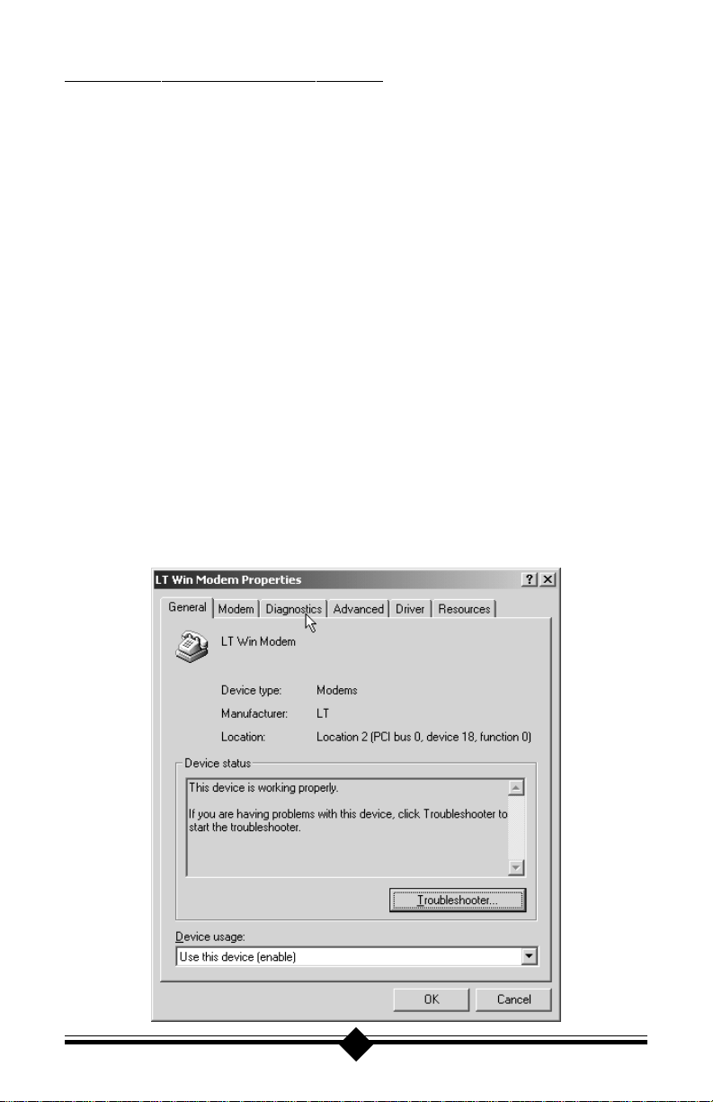
Step 4 In Device Manager, click the plus (+) sign next to Modems to expand that
section of the listing. A listing for LT Win Modem should appear.
Note: Windows did not display anything when you started up your computer to
acknowledge the fact that you had installed a new modem. This was because it recognized the modem as one corresponding with one of the generic drivers that come as part of Windows 2000, in this case the “LT Win
Modem” driver . In the steps that follow we will effectively tell Windows to
use the Actiontec driver instead, which will allow you to take full advantage
of the modem’s features and capabilities.
22
Page 24
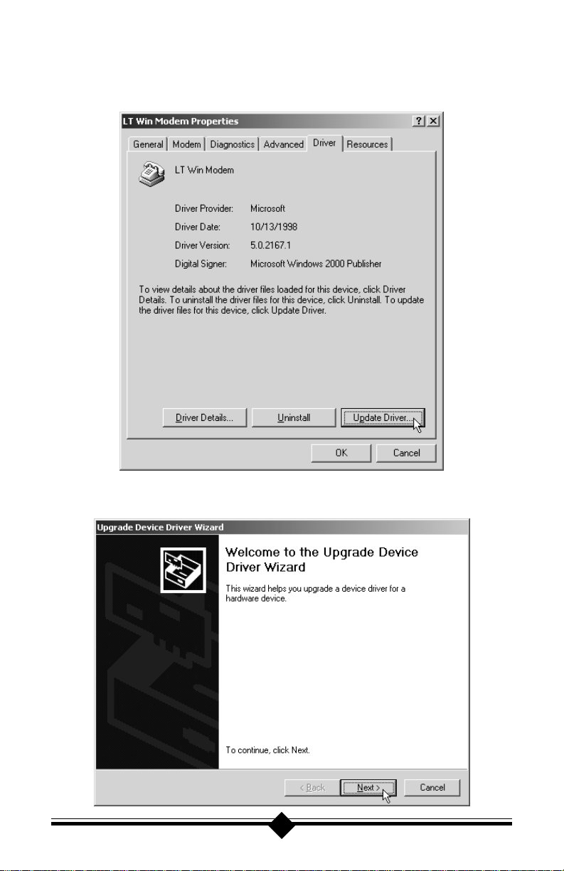
Step 5 Double-click on the listing for L T Win Modem. An LT Win Modem Prop-
erties dialog box will appear. Click on the S tep Driver tab to bring it to the
front, then click Update D r iver.
Step 6 This will start the Update Device Driver Wizard. Click Next.
23
Page 25
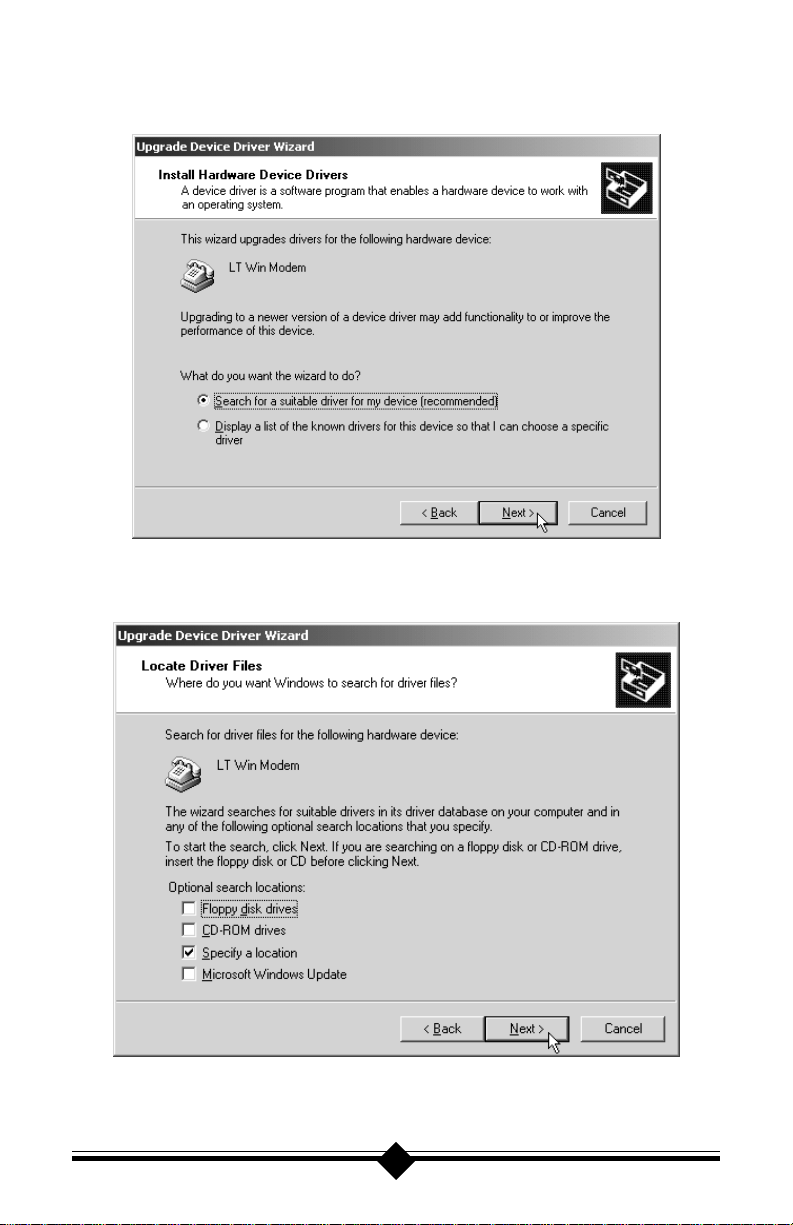
Step 7 In the dialog box that appears next (shown below) make sure “Search for a
sutiable driver for my device (recommended)” is selected then click Next.
Step 8 In the dialog box that appears next, make sure that “Specify a location” is
the only option selected, then click Next.
24
Page 26

Step 9 Click Browse. Navigate to your CD-ROM drive, then double click on the
Drivers folder. In Drivers, double-click the Pciwin folder, then double-
click the Win2K folder. With the Win2k folder open in the Locate File
dialog box, click Open.
Step 10 You will be sent back to the Upgrade Device Driver Wizard, but now the
path in the Copy manufacturer’s files from: box is correct. click OK.
Step 11 You will be returned to the Upgrade Device Driver wizard and Windows
2000 will confirm the name and location of the driver. Click Next.
Step 12 Next, windows will report that the drivers have not been tested by Microsoft
for use with Windows 2000. Actiontec itself has exhaustively tested this
product for use with Windows 2000. Click Yes to continue the installation.
25
Page 27

Step 13 Windows will report that the modem has been properly associated with the
new driver. Click Finish.
Step 14 Windows will return you to what was the “LT Win Modem Properties”
dialog box, now called “V.90 PCI Windows Modem (LHV) Properties.”
Click Close.
Step 15 In the dialog box that appears next, click Yes to restart your computer.
26
Page 28

Confirming the Installation of the Driver in Windows 2000
Step 16 After the system has restarted, on the desktop, click Start, then click Set-
tings then click Control Panel. In Control Panel double-click the icon for
Phone and Modem Properties. The dialog box shown below will appear.
Step 17 Click the Modem tab to bring it to the front. Make sure that “V.90 PCI
Windows Modem (LHV) is listed and selected,then click Properties.
27
Page 29

Step 18 In the dialog box that appears next, click the Diagnostics tab to bring it to
the front, then click Query Modem. After windows has communicated with
the new modem some A T commands and their responses will appear. Scroll
through this section of the dialog box until you see the commands and
responses displayed below.
If the displayed responses are similar to those shown above, the modem and
its correct driver have been installed correctly.
28
Page 30

Installing Communications Software
If your modem came with a communications software package, it is strongly recommended that you use this software for your modem. Its default installation parameters have been specially configured to work with this modem. The Users Guide for
this program can be found in Adobe Acrobat (PDF) format on the installation CDROM.
Some configurations are packaged without communications software. Check your
packaging to see if communications software is included.
If you wish to use another software package, please be sure that it supports this modem. Most Software Manufacturers have a listing of supported modems on their
websites or BBSs. Check these sites to see if this model is supported. If you are unsure
or your brand of software supports only a few modems, try selecting “Hayes Compatible” or “Standard Modem”. This may work in certain cases.
Some software programs allow manual input of parameters. For the users of these
programs, here is a listing of the Data/Fax/Voice Command Standards supported.
Data: TIA/EIA-602
Fax: TIA/EIA-578 for Class 1 Fax
Voice: TIA IS-101 support for TAD (Telephone Answering Device)
Init String: AT&F&C1&D2W2
TIA IS-101 Commands not supported:
Caller ID
Full Duplex Speakerphone
VoiceView
Note: some programs must be configured to communicate with the modem on
the same COM port and or IRQ setting used by the modem. See the “Installing the Modem ” for instructions on how to determine your COM port
and IRQ settings.
The Modem’s Voice Features
This modem supports TIA IS-101 commands applicable to a Telephone Answering
Device. In order to take advantage of this feature, you will need a Sound Blaster
compatible sound card equipped with an external microphone and external speakers.
A software application which supports these TAD functions (such as the one supplied with the modem) is also required.
29
®
Page 31

A modem based Telephone Answering Machine works by using a sound card equipped
with a microphone to record an outgoing message. This message is stored as a .wav
file which is transferred to the modem by the application program when an incoming
call is detected. The modem’s internal electronics conver ts the digital information
contained in the .wav file into an audio signal which is then sent over the phone line.
The person calling hears your outgoing message and responds with an incoming
message.
The sequence of recording an incoming message is the reverse of an outgoing message. The modem converts the audio signal into a digital format and sends it to the
application program. The application program then formats and stores the incoming
message as a .wav file. When you play back your stored messages by selecting them
from within the application program, they are sent to the sound card. You then hear
your recorded messages through the sound card’s speakers.
The default parameters of the software which came with your modem have been
specially configured to identify and use your modems voice capabilities. Even if you
have decided to use another third-party application, try your included application
first. This will allow you to test the modem and its voice functions before inv esting in
an expensive retail software package.
30
Page 32

Troub leshooting
This section lists some common problems and offers suggestions for a solution. It is
important to remember that this modem is a Windows-based modem and requires
32bit virtual device drivers. It therefore cannot work in W indows 3.1 which cannot
use these drivers. The modem also cannot work in DOS regar dless of version. It is a
software installed device and has no provisions for manual configuration.
If you cannot find your particular symptom listed here, it is suggested that you remove the modem and its drivers from the system and reinstall them again. (See
“Uninstalling the Modem” later in this section.) This provides a “clean” installation
and can cure many temporary problems. See “Do This First” for before reinstalling
the modem.
Most problems encountered during the Windows 95/98/NT installation process ar e
a result of insufficient system preparation. Make sure to physically remove any previously installed modems from your system.
If your modem has installed but is not functioning, try the troubleshooting procedure listed below .
Windows 95/95B/98
Step 1: Check System Resour ces
On the taskbar, click Start. On the Start menu, click Settings, then click Control
Panels, and double-click the System icon. Select the Device M anager tab. F r om the
device tree, double-click the Modems icon to show what modems are installed. If
there is no Modems icon, your modem did not install (See “Does Not Install”.) If
your modem is listed, check that there is no yellow exclamation mark or red “X” over
the modem’s icon (if there is, go to step 2). If any other modems are listed, highlight
the modem by clicking once on the icon next to the listed modem and then click on
the Remove button. Turn off the system. Wait 5 seconds and turn your computer
back on and repeat step 1.
Step 2: Check Modem Pr operties
In the Device Manager tab of System Properties, double-click the Modems icon to
show what modems are installed. Highlight your modem by clicking once on the
icon and then click the Properties button. Read the Device Status under the General
tab to see if the device is working properly. Check the Device Usage area and make
sure “Disable in this hardware profile” ( Windows 95B and 98 only) or the box labeled “Original Configuration, Current” has a check mark (for Windo ws 95 or 95A.)
31
Page 33

If either of these conditions are present, correct them. Make a note of the Com port
and IRQ the modem is using. If the Device Status area shows some error message, it
will generally be about a conflict. Go to the Resources tab and read the Conflicting
Device List. If a conflict is present, click to deselect “Use automatic settings” and
select a configuration that does not cause conflicts. Manually change the IRQ settings if needed (see your Windows 95 or 98 on-line help file for a more detailed
discussion on changing these settings). Click the OK button. If there is no setting
free of conflicts, See “Does Not Install.”
Step 3: Modem Diagnostics
On the taskbar, click Start. On the Start menu, click Settings, then click Control
Panel and double-click the Modems icon. Y our modem should be listed. If any other
modem is listed, click once on each old modem and then click the Remove button. It
is a good idea to turn off your computer, wait 5 seconds and turn the power back on.
Return to Modems and click the Diagnostics tab. Highlight the modem by clicking
once on the COM port icon next to its listing. Now click the More Info button. You
should see the panel below.
Figure 8: More Info P anel
If you receive an error message or the panel is blank, see “Does Not Install” section.
32
Page 34

Step 4: Does Not Install
The most likely reason for a non-installation in Windows 95 or 98 is a lack of IRQ
resources. The modem needs one IRQ and two I/O addressees in order to function.
Modern computer systems are usually equipped with sound card, CD-ROM drive,
Hard-drive, floppy drive, video card, two COM P orts, one LPT port, keyboard, and
a mouse. Each of these devices require at least one IRQ (interrupt) in order to function.
This section deals with the process of freeing IRQ’s and configuring the system for
Plug-N-Play requiring that you know how to enter your computer system’s BIOS
Setup Routine (read your computer user’s manual for information on how to invoke
and use the BIOS setup).
Once inside the BIOS Setup, find the Plug-N-Play configuration. This can be found
within the “Advanced”, “PNP/PCI Configuration”, or “Plug and Play Configuration” section depending on the BIOS Manufactur er . Next, from the information you
noted in Step 2. Find the interrupt selection for the IRQ your modem is using.
(Some BIOSs do not allow individual selection of interrupts to ISA, Plug-N-Play , or
PCI.) Y ou want to set this so that the PCI bus has access to this interrupt. This can be
called ICU/PCI, PCI, or PNP depending on your BIOS version and manufacturer.
Do not set this interrupt to “ISA” only or to “Legacy ISA”.
If you do not have any free interrupts available, you will have to disable some unused
function of your computer system. If you are using a PS/2 style mouse, you may be
able to spare one of your internal COM ports. To disable a COM port, find the
BIOS Setup section for “Integrated Peripherals”. Locate the Serial Port settings and
disable an unused port that has nothing connected to it This will often be serial port
2. This should free one IR Q for your modem to use. You may also have to disable the
COM Port in Windo ws.
Although it is possible for a PCI card to share interrupts, it is recommended that you
have one free IRQ available in your computer. The modem needs one IRQ and two
I/O Addresses to function. To check for any available interrupts in your system,
right-click on the My Computer icon, choose Properties, and select the Device Man-
ager tab. Click the Properties button to view the System Resources.
Their are 16 (0-15) interrupts available in a system. Make a note of any interrupt not
listed. To make sure that an available interrupt is assigned to the PCI bus, go to your
system BIOS Setup routine and find the Plug-N-Play settings. These are found in the
“Advanced”, “PNP/PCI Configuration”, or “Plug and Play Configuration” sections
depending on the BIOS Manufacturer.
Next, verify that one fr ee IRQ has been set so that the PCI bus has access to it. (Some
33
Page 35

BIOSs don’t allow individual selection of interrupts for ISA, Plug-N-Play, or PCI.)
The interrupt settings can be called “ICU”, “ICU/PCI”, “PCI”, or “PNP depending
on your BIOS version and manufacturer. Do not set this interrupt to “ISA” only or
to “Legacy ISA”. Be sure to Save the settings before exiting the BIOS Setup.
Under some situations, you will find that freeing an interrupt does not solve your
installation difficulties. This could be due to another peripheral device stealing the
interrupt you just provided. Certain full-featured sound cards require three IRQs to
support all their functions. When one becomes available, they take it. This situation
requires that you remove your sound card, free an interrupt, install the modem and
verify its operation, and then reinstall the sound card. This procedure may also work
for sound cards that have lost their sound after the modem has been installed or if the
modem will not install in a system with a sound card.
Proceed to “Installing the Modem”.
Windows NT 4.0
Windows NT installation problems are always due to inadequate preparation. The
following conditions must be meet before attempting to install the modem or it will
not be seen or correctly installed by the system. (See “Do This F irst” at the beginning
of this manual.)
• You must have the latest Windows NT Service Pack installed.
• There must be two IRQ and two I/O port Addresses available for the modem to
use.
• The installation utility must be copied from the installation CD-ROM to the
default hard drive and extracted.
If you need help on freeing an interrupt or making a COM Port available, see the
Windows 95/98 “Does Not Install” section for a discussion of this topic. The “Special Situations” and “Plug-N-Play BIOS” sections also apply to Windows NT 4.0.
See these areas for guidelines. If you are upgrading or removing the drivers, use the
installation utility on the Windows NT installation diskette that came with your PCI
modem. This utility has an option for removing the modem drivers.
If you are not familiar with changing the settings within your system BIOS setup,
you should skip the following system pre-installation procedure and go to “Installing
the Modem.” Refer back to this area only if you have a problem installing the modem.
Check your system BIOS IRQ assignments and make sure that at least two interrupts
have been assigned to the PCI bus. In your system’s BIOS Setup routine, find the
34
Page 36

Plug-N-Play settings. These settings can be found within the “Advanced,” “PNP/
PCI Configuration,” or “Plug-and-Play Configuration” sections depending on the
BIOS Manufacturer . Next, verify that at least two IR Qs have been set so that the PCI
bus has access to them (some BIOS don’t allow individual selection of interrupts to
ISA, Plug-N-Play, or PCI). These settings can be called ICU, ICU/PCI, PCI, or
PNP depending on your BIOS version and manufacturer. Do not set all the interrupts to “ISA” only or to “Legacy ISA”. Pay attention to the IR Q usage of the other
peripherals in your system. Do not reassign an interrupt that is already in use by an
ISA card to the PCI bus.
Common Problems
No Dialtone Error
Make sure you have connected the phone cable into the right connector on the back
of the modem. See Figure 7.
Y ou may have too many devices connected to the phone line. Remove all other equipment.
Your modem may not recognize overseas dialtone. Use the AT command ATX0 to
have the modem ignore (not look for) the dialtone before dialing. (See Appendix A
for information on how to use AT commands.)
Communications Software Does Not W ork
Some communications software packages need to be configured to the same COM
port and or IRQ as the modem. See the “Installing the Modem” for information on
how you determine your COM Port and IRQ number.
Does the communications software support this modem? See the Installing and Con-
figuring Communications Software section.
If you are using a different software from the one supplied with the modem (some
models of this modem may be shipped without communications software), try installing the supplied software and verify its functionality with the modem.
Nothing Appears On The Screen When I Type
Issue the AT command ATE1 to the modem to enable command echo. This will let
you see what you type.
35
Page 37

Can’t Connect at 56K
Note: Current FCC regulations limit your maximum connection rate to 53Kbits / s.
The number you are calling may not support V.90 or K56flex protocols. Some ISPs
(Internet Service Provider) have special numbers that you must call to connect to
56K. Contact your service provider and ask if the number you are calling supports
V.90 or K56flex connections to their service.
Check the maximum speed setting in the Modem Properties window. On the taskbar, click S tart. On the Start menu, click Settings, then click Control Panels. Double-
click the Modems icon. Highlight your modem by clicking once on the icon next to
the modem and then click the Properties button. Select the General tab and look at
the setting in the Maximum speed box. Make sure this is set to 115200.
You may have other telephone devices connected to the phone line. To help your
modem achieve the best connection possible, remove all extra devices and their cables
from the telephone line when the modem is in use. This reduces the load on your
phone line and keeps signal attenuation to a minimum.
Keep the length of your phone line cable to 10 feet or less. Don’t use an unusually
long cable to connect to the phone line socket. If necessary, move the computer
closer to the phone socket. Don ’t lay your cabling close to an electrical appliance like
a refrigerator or air conditioner unit. High current devices can transmit a 60 cycle
“hum ” to your modem thr ough the phone cor d. This may cause frequent renegotiations or line disconnects while the appliance is running.
The telephone line conditions at the time of your call may not let you connect at
56K. The modem has a connection sequence of K56flex, then V.90, then V.34, and
so on. The modem attempts to make the highest connect rate that your telephone
line can support at the time of negotiation. If the line conditions (noise, telephone
company routing, etc.) won ’ t allow a high data rate connection, then the modem will
automatically connect at the most reliable rate. Try making the call again after a few
minutes. The routing of the call may improv e your chances of making a 56K connection.
If you are attempting to make a call from an office, are you using a direct outside line
or are you using a PBX hookup? If you have to dial “9” to reach an outside number ,
you are using a PBX. The modem cannot connect faster then V.34 if you are using a
PBX. Try using the line that is connected to a fax machine. Fax machines are usually
connected to a dedicated line and not through the PBX.
Y our phone line may not support a 56K connection. Or may support a 56K connection only intermittently. There are many conditions that must be met before a 56K
36
Page 38

connection can be established. The telephone company must have you connected to
the PSTN (Public Switched Telephone Network) in a particular way. The modem
you are calling must support the same protocol. The phone line must be free of
distortion and noise. The phone wiring in your house or building must be in good
condition and so on. Check to see if you have good voice communications while
talking to friends or relatives. Do their voices sound distorted? Do you hear a “hissing” or “humming” sound in the background? I s there “ popping ” or “ crackling” during your call? These are phone line problems. In the case of distortion, your phone
line is bad. Humming may be due to the cabling inside your residence coming too
close to a high current appliance or you may have a cordless phone recharger base
connected to the phone line. Popping or crackling usually indicates a loose connection to the outside line or water dripping on the hookup outside your house.
The drivers for your modem are constantly being refined to address problems with
compatibility, interoperability, and performance. Check the Actiontec website on a
regular basis for driver upgrades. A problem connecting to a particular provider might
be fixed by a simple software upgrade.
Uninstalling the Modem
If you are uninstalling the modem in Windows 95 or 98 in order to upgrade your
drivers or obtain a clean reinstallation, it is important to follow these directions carefully .
When removing the drivers from a system running Windows NT, use the installation
utility. The utility has an option to remo ve your modem drivers.
Uninstalling in Windows 95 and 98
Step 1 On the desktop, right-click the My Computer icon and choose Properties
from the menu that appears. Select the Device Manager tab. D ouble-click
the Modems icon to expand the M odems section of the list. Highlight your
modem by clicking once on its icon, then click Remove.
Step 2 On the taskbar, click Start. On the Start menu, click Settings, then click
Control Panel and double-click the Modems icon. If your modem is listed,
highlight the modem by clicking once on the icon next to the modem and
then click the Remove button. Or, if the New Hardware dialog box comes
up, click Cancel.
Your modem should not be listed in the Modems section after you have
deleted it from the Device Manager. This could be a sign that your Plug-NPlay settings are not correct. See “Does Not Install” for more information
about Plug-N-Play.
37
Page 39

Step 3 Close all open windows and return to the desktop. On the taskbar, click
Start. On the Start menu, click Find, then click F iles or F olders. Search for
the files listed below. Type in the name and extension (e.g. ltwave.inf) and
click the Find button. Once you find each of the files listed, highlight the
file by clicking once on the file name and then, in the Find All Files dialog
box, click to show the File menu and choose Delete. Delete all occurrences
of these files in your system.
ltcom.vxd ltwave.inf
ltmodem.vxd ltdfv.inf
ltvcd.vxd ltdt.inf
ltmodem.sys ltports.inf
ltdsvd.dll
If you cannot find a particular file, it usually means it was not installed. After all
instances of these files have been deleted, restart your system.
Note to users of Windows 95 and 98
If you are using Windows 95B (see “Do This F irst” for instructions on how to determine your Windows 95 version), you need only delete the files listed. In the case of
Windows 95 or Windows 95A, there are two additional files which Windows 95 or
Windows 95A generates when installing a third-party hardware peripheral. The file
is called oem#.inf. The number (#) used is generated by Windows 95 each time
an additional piece of hardware is installed. In the case of the modem, these files
could have any number between 1 and 99--oem8.inf, for example.
Close all open windows and return to the desktop. On the taskbar, click Start. On
the Start menu, click Find, then click Files or F olders. T ype in *.inf in the N amed
box. Make sure your entire drive is selected and not just one subdirectory. Place a
check mark in the Include subfolders box. Be sure all the information is typed in as
shown below. Before beginning the search, click the Advanced tab.
38
Page 40

At the Advanced settings window, type the following in the Containing text field:
V.90 PCI Windows Modem. Click Find Now.
When a file is found, it will have the name oem#.inf. To delete a file, highlight
the file name by clicking once and then choose Delete from the File menu.
Next, go to the Advanced tab and type the following in the Containing text field:
V.90_PCI_Windows_Modem as shown below.
After Windows finds the other file, delete it as before. Restart your system and follow
the installation procedures outlined in the “Installing the Modem.”
39
Page 41

AT Command Set
AT Commands
AT commands are issued to the modem to control the modem’s operation and software configuration. AT commands are commonly entered from a terminal program
such as HyperTerminal, and can only be entered while the modem is in command
mode. To enter an AT command, type:
ATXn
where X is the AT command, and n is the specific value for that command. Press
ENTER.
Commands are acknowledged with either text or numeric value response known as a
result code. In the case of multiple AT commands on the same command line, the
commands are executed in the order they are received. Should execution of a command result in an error, or a character not be recognized as a valid command, execution is terminated, the remainder of the command line is ignored, and the ERROR
result code is issued. If all commands execute correctly, only the result code associated with the last command shall be issued, even though all have been executed.
In the following listing all commands and command values accepted by the modem
are shown. Any entries other than those shown cause the ERROR result code.
+++ Escape sequence
The escape sequence allows the modem to exit data mode and enter on-line command mode. While in on-line command mode, you may communicate directly to
your modem using AT commands. Once you are finished, you may return to data
mode using the ATO command. A pause, the length of which is set by the Escape
Guard T ime S-Register (S12--S ee the “S-Registers R eference ” section of this manual
for details), must be used after an escape sequence is issued. This pause prevents the
modem from interpreting the escape sequence as data. The value of the escape sequence character may be changed using Register S2.
A/ Repeat Last Command
This command repeats the last command string entered. Do not precede this command with an AT prefix or conclude it by pressing Enter.
A Answer Command
This command instructs the modem to go off-hook and answer an incoming call.
40
Page 42

Bn Communication Standard Setting
This command allows you to choose between CCITT and Bell standard.
dnammoCtceffE
0B
1B
2B.)3Bsaemas(lennahcesrever32VstcelesnU
3B.)2Bsaemas(lennahcesrever32VstcelesnU
51B.s/stib003tasimedomehtnehw12.VstceleS
.s/stib
.)tluafed(
0021tasimedomehtnehwedom22.VTTICCstceleS
s/stib0021tasimedomehtnehwA212lleBstceleS
61B
.)tluafed(
s/stib003tasimedomehtnehwJ301lleBstceleS
Result Codes:
KO61,51,1,0=n
RORREesiwrehtO
Cn Carrier Control
The modem will accept the C1 command without error in order to ensure backward
compatibility with communications software that issues the C1 command. However ,
this modem does not support the C0 command. The C0 command may instruct
some other modems to not send a carrier, in effect putting them in a receive-only
mode.
dnammoCtceffE
0C.ffosyawlareirractimsnarT
1C.gnihctiwsreirractimsnartlamroN
Result Codes:
KO1=n
RORREesiwrehtO
41
Page 43

Dn Dial
This command instructs the modem to begin the dialing sequence. The dial string
(n, including modifiers and the telephone number) is entered after the ATD command.
A dial string can be up to 40 characters long. Any digit or symbol (0-9, *, #, A, B, C,
D) may be dialed as touch-tone digits. Characters such as spaces, hyphens, and parentheses do not count, they are ignored by the modem and may be included in the
dial string to enhance readability.
The following characters may be used as dial string modifiers:
gniwollofretcarahctsrifehtebdluohS.rebmuntsalslaideR
L
.delaidrebmuntsal
P).tluafedsaeslupottesgnilaiD.xxxPDTA.g.e(.gnilaidesluP
gnirtsgnilaidehtsyalpsidmedomehT.esiwrehtoderongi,DTA
ehtsixxxxxxxerehwxxxxxxxgnilaiD:tamrofgniwollofehtni
T
,
W
@
!
;
^.noissimsnartenotgnillacatadelbasiD
n=S
$.noitcetedenotgnoB
).tluafedsa
.gnirtslaidehtgnissecorp
.resuehtotkcabedoctluserREWSNAONa
.kooh-ffootnruternehtdna
.llaceht
.3-0sinfoegnarehT
enotottesgnilaiD.xxxTDTA.g.e(.)tluafed(gnilaidenot-hcuoT
8SretsigeRnideificepsemitrofesuaP.gnilaidgnirudesuaP
.gnirtslaidehtniretcarahctxenehtgnissecorperofeb
erofebenotlaiddnocesarofstiawmedoM.enotlaidroftiaW
retfaecnelisfosdnocesevifroftiaW.rewsnateiuqroftiaW
sdnesmedomeht,detcetedtonsiecnelisfI.rebmunehtgnilaid
sdnoces5.0rofkooh-noogotmedomehtsesuaC.hsalfkooH
otnruterotmedomehtsesuaC.edomdnammocotnruteR
gnitcennocsidtuohtiw,rebmunehtgnilaidretfaedomdnammoc
x=nZ&ehtgnisuderotsylsuoiverprebmunenohpeletalaiD
.)noitamrofnirehtrufrofdnammocx=nZ&ehtees(dnammoc
En Echo Command
This command controls whether or not the characters entered from your computer
keyboard are echoed back to your monitor while the modem is in command mode.
42
Page 44

dnammoCtceffE
0E.retupmocehtotohceselbasiD
1E.)tluafed(retupmocehtotohceselbanE
Result Codes:
KO1,0=n
RORREesiwrehtO
Fn Online Data Character Echo Command
This command determines if the modem will echo data from the DTE. This modem
does not support the F0 version of the command. However, the modem will accept
F1, which may be issued by older communication software, to assure backward compatibility .
dnammoCtceffE
0F
1F.delbasidohceretcarahcenilnO
.)RORREnruterlliw
,detroppustoN(delbaneohceretcarahcatadenilnO
Result Codes:
KO1=n
RORREesiwrehtO
Hn Hook Control
This command instructs the modem to go on-hook to disconnect a call, or off-hook
to make the phone line busy.
dnammoCtceffE
0H.)tluafed(kooh-noseogmedoM
1H.kooh-ffoseogmedoM
Result Codes:
KO1,0=n
RORREesiwrehtO
43
Page 45

In Request ID Information
This command displays specific product information about the modem.
dnammoCtceffE
OI)3Isaemas(.ledommedomehtsnruteR
1I .)BA21,.g.e(ETDehtnotisyalpsiddnamuskcehcMORsetaluclaC
2I
3I)0Isaemas(.ledommedomehtsnruteR
4I.)49,.g.e(pmupatadrofnoisreverawmrifsnruteR
5I.noisrevrevirdehtsnruteR
6IKOesnopseR
7IKOesnopseR
8IKOesnopseR
9I.)1.reVaciremAhtroN,.g.e(edocyrtnuocsnruteR
.RORREroKOgniyalpsid
muskcehcehtseifirevdnasetaluclacdnakcehcMORasmrofreP
Result Codes:
KO9-0=n
RORREesiwrehtO
Ln Monitor S peaker Volume
This command sets speaker volume to low, medium, or high.
dnammoCtceffE
0L.emulovtsewolstceleS
1L.emulovwolstceleS
2L.)tluafed(emulovmuidemstceleS
3L.emulovhgihstceleS
Result Codes:
KO3,2,1,0=n
RORREesiwrehtO
44
Page 46

Mn Monitor Speaker M ode
This command turns the speaker on or off.
dnammoCtceffE
0M.ffosirekaepsehT
1M
2M.kooh-ffosimedomnehwnosyawlasirekaepsehT
3M
.)tluafed(langis
.gnilaidelihw
reirracehtstcetedmedomehtlitnunosirekaepsehT
tpecxe,detcetedsireirracehtlitnunosirekaepsehT
Result Codes:
KO3,2,1,0=n
RORREesiwrehtO
Nn Modulation Handshake
This command controls whether or not the local modem performs a negotiated handshake at connection time with the remote modem when the communication speed of
the two modems is different.
0N
1N
Result Codes:
KO1,0=n
dnammoCtceffE
ekahsdnahrofsisiht,gnirewsnarognitanigironehW
73Sybdeificepsdradnatsnoitacinummocehttaylno
.dnammocBTAehtdna
ekahsdnahehtnigeb,gnirewsnarognitanigironehW
73Sybdeificepsdradnatsnoitacinummocehttaylno
otkcabllaf,ekahsdnahgniruD.dnammocBTAehtdna
.)tluafed(ruccoyamdeepsrewola
RORREesiwrehtO
45
Page 47

On Return On-line to Data Mode
dnammoCtceffE
0O
1O
3O
.edomatadenil
.edomatadenilnootgninruter
dnaedomdnammocenil-notixeotmedomehtstcurtsnI
.)+++,ecneuqeSepacsETAees(edomatadotnruter
-nootgninrutererofebniarteraseussidnammocsihT
erofebnoitaitogeneretaraseussidnammocsihT
Result Codes:
KO3,1,0=n
RORREesiwrehtO
P Select Pulse Dialing
This command configures the modem for pulse (non-touch-tone) dialing. Dialed
digits are pulsed until a T command or dial modifier is received. Tone dial is the
default setting.
Qn Result Code Control
Result codes are informational messages sent from the modem and displayed on your
monitor. Basic result codes are OK, CONNECT, RING, NO CARRIER, and ERROR. The ATQ command allows the user to turn result codes on or off.
dnammoCtceffE
0Q
1Q
.)tluafed(
.retupmoc
retupmocehtotsedoctluserdnesotmedomselbanE
ehtotsedoctlusergnidnesmorfmedomselbasiD
Result Codes:
KO1,0=n
RORREesiwrehtO
46
Page 48

T Select Tone Dialing
This command instructs the modem to send DTMF tones while dialing. Dialed
digits are tone dialed until a P command or dial modifier is received. This is the
default setting.
Vn DCE Response Format
This command controls whether result codes (including call progress and negotiation progress messages) are displayed as words or their numeric equivalents.
dnammoCtceffE
0V.txetsyawlaerastluseR.detroppustoN
1V.)tluafed(txetsasedoctlusersyalpsiD
Result Codes:
KO1,0=n
RORREesiwrehtO
Wn Result Code Option
Result Codes:
KO2,1,0=n
dnammoCtceffE
0W
1W
2W
RORREesiwrehtO
.sedoctluserlocotorp
.sedoctluserlocotorp
.)tluafed(sedoctluserlocotorp
elbasiD.deepsETDstroperedoctluserTCENNOC
elbanE.deepsETDstroperedoctluserTCENNOC
elbanE.deepsECDstroperedoctluserTCENNOC
47
Page 49

Xn Result Code Selection and Call Progress Monitoring
This command enables tone detection options used in the dialing process. As these
functions are chosen, the result codes are also affected. Therefore, this command is
frequently used to control the modem chipset’s responses. The primary function of
this control is to control the modem chip set’s call response capabilities.
dnammoCedoCtluseRtceteDenoTlaiDtceteDenoTysuB
0XelbasiDelbasiDelbasiD
1XelbanEelbasiDelbasiD
2XelbanEelbanEelbasiD
3XelbanEelbasiDelbanE
4XelbanEelbanE)tluafed(elbanE
5XelbanEelbanEelbanE
6XelbanEelbanEelbanE
7XelbasiDelbanEelbanE
Extended Result Codes
dednetxE
sedoCtluseR
delbasiD
delbanE
Dial Tone Detect
enoTlaiD
tceteD
delbasiD
delbanE
tceffE
,TCENNOC,KOsedoctlusercisabehtylnosyalpsiD
.RORREdna,REIRRACON,GNIR
tcennocehthtiwgnola,sedoctlusercisabsyalpsiD
nadna,etaratadsmedomehtdnaegassem
ataddnanoitcerrocrorresmedomehtfonoitacidni
.noitareponoisserpmoc
tceffE
stcetedtirehtehwfosseldragerllacaslaidmedomehT
erofebstiawmedomehtemitfodoirepehT.enotlaida
.6Sretsigernideificepssignilaid
,enotlaidafonoitcetednopuylnoslaidmedomehT
detcetedtonsienotlaidehtfillacehtstcennocsiddna
.sdnoces01nihtiw
48
Page 50

Busy Tone Detect
enoTysuB
tceteD
delbasiD.seviecertisenotysubynaserongimedomehT
delbanE.senotysubrofsrotinommedomehT
tceffE
Result Codes:
KO
RORREesiwrehtO
,2,1,0=n
7,6,5,4,3
Yn Long Space Disconnect
Long space disconnect is always disabled.
dnammoCtceffE
0Y.)tluafed(tcennocsidecapsgnolelbasiD
1Y).detroppustoN(.tcennocsidecapsgnolelbanE
Result Codes:
KO0=n
RORREesiwrehtO
Zn Recall Stored Profile
This command instructs the modem chip set to go on-hook and restore the profile
saved by the last &W command. Either Z0 or Z1 restores the same single profile.
Result Codes:
KO1,0=n
RORREesiwrehtO
49
Page 51

&Bn V.32 A uto Retrain
This modem always auto retrains.
dnammoCtceffE
0B&).detroppustoN(niarterotua23.VelbasiD
1B&.)tluafed(niarterotua23.VelbanE
Result Codes:
KO1=n
RORREesiwrehtO
&Cn D ata Carrier Detect (DCD) Control
Data Carrier Detect is a signal from the modem to your computer indicating that the
carrier signal is being received from a remote modem. DCD normally turns off when
the modem no longer detects the carrier signal.
dnammoCtceffE
0C&
1C&
.)tluafed(detceted
.nosyawlasitiucricDCD.derongi
simedometomerehtmorfreirracehtfoetatsehT
langisreirracsmedometomerehtnehwnosnrutDCD
tonsilangisreirracehtnehwffodna,detcetedsi
Result Codes:
KO1,0=n
RORREesiwrehtO
50
Page 52

&Dn DTR Control
This command interprets how the modem responds to the state of the DTR signal
and changes to the DTR signal.
dnammoCtceffE
0D&
1D&
.detcennocsniamerdna,edoctluser
2D&
3D&
.deviecersawdnammoc
dnaRTDfosutatseurtehtserongimedomehT.erongI
ruoyfidesuebylnodluohssihT.nosyawlasatistaert
.medomehtotRTDedivorptonseodretupmoc
atadenil-nonielihwdetcetedtonsilangisRTDehtfI
KOseussi,edomdnammocsretnemedomeht,edom
atadenil-nonielihwdetcetedtonsilangisRTDehtfI
silangissihtfI.)tluafed(stcennocsidmedomeht,edom
.laidrorewsnatonlliwmedomeht,tneserpton
,srucconoitisnartffo-ot-nonanehwlangisRTDrotinoM
ZTAehtfisatesertfosasmrofrepmedomeht
Result Codes:
KO
3
RORREesiwrehtO
,2,1,0=n
&Fn Load Factory Settings
This command loads the configuration stored and programmed at the factory. This
operation replaces all of the command options and the S-register settings in the active configuration with factory values.
dnammoCtceffE
0F&)tluafed(.noitarugifnocevitcasagnittesyrotcafllaceR
&Gn V .22bis G uard Tone Control
This command determines which guard tone, if any, to transmit while transmitting
in the high band (answer mode). This command is only used in V.22 and V.22bis
mode. This option is not used in North America and is for international use only.
dnammoCtceffE
0G&.)tluafed(delbasidenotdrauG
1G&.zH055otenotdraugsteS
2G&.zH0081otenotdraugsteS
51
Page 53

Result Codes:
KO2,1,0=n
RORREesiwrehtO
&Jn Auxiliary Relay option
dnammoCtceffE
0J&.desolcrevensiyaleryrailixuaehT
1J&.RORREsdnopser,DETROPPUSTON
Result Codes:
KO0=n
RORREesiwrehtO
&Kn Local Flow Control S election
dnammoCtceffE
0K&.lortnocwolfelbasiD
1K&.devreseR
2K&.devreseR
3K&.)tluafed(lortnocwolfSTC/STRelbanE
4K&.lortnocwolfFFOX/NOXelbanE
Result Codes:
KO4,3,0=n
RORREesiwrehtO
&Mn Asynchronous Communications Mode
dnammoCtceffE
0M&.)tluafed(edomsuonorhcnysA
1M&.devreseR
2M&.devreseR
3M&.devreseR
4M&.devreseR
52
Page 54

Result Codes:
KO0=n
RORREesiwrehtO
&Pn Pulse Dial Make-to-Break Ratio Selection
This Command is effective only for use in Japan.
dnammoCtceffE
0P&SPP01,oitarkaerb/ekam16/93
IP&)tluafed(SPP01,oitarkaerb/ekam76/33
2P&SPP02,oitarkaerb/ekam76/33
Result Codes:
KO2,1,0=n
RORREesiwrehtO
&Qn Asynchronous Communications Mode
dnammoCtceffE
0Q&.0N\saemaS.dereffub,edoMsuonorhcnysA
1Q&.devreseR
2Q&.devreseR
3Q&.devreseR
4Q&.devreseR
5Q&.3N\saemaS.)tluafed(dereffub,edoMlortnoCrorrE
6Q&.0N\saemaS.dereffub,edoMsuonorhcnysA
7Q&.devreseR
8Q&
9Q&
lortnocrorrePNMnafI.edomlortnocrorrePNM
kcabllaflliwmedomeht,dehsilbatsetonsilocotorp
.63Snignittesresutnerrucehtotgnidrocca
lortnocrorrerehtienfI.edomlortnocrorrePNMro24.V
kcabllaflliwmedomeht,dehsilbatsesilocotorp
.63Snignittesresutnerrucehtotgnidrocca
53
Page 55

Result Codes:
KO
RORREesiwrehtO
,6,5,0=n
9,8
&Sn Data Set Ready (DSR) Option
This command selects DSR action.
dnammoCtceffE
0S&.)tluafed(NOsyawlaRSD
1S&
.sdnenoitcennocehtnehwffoseog
dnanoitcennocagnihsilbatsenehwnosemocRSD
Result Codes:
KO1,0=n
RORREesiwrehtO
&V0 View Active Configuration and Stored Pr ofile
This command is used to display the active profiles.
dnammoCtceffE
0V&elifevitcaweiV
Below is an example of a possible output:
Option Selection AT Cmd
Comm Standard Bell B
CommandCharEcho Enable E
Speaker Volume Medium L
Speaker Control OnUntilCarrier M
Result Codes Enable Q
Dialer Type Tone T/P
ResultCode Form Text V
ExtendResultCode Enabled X
DialTone Detect Enable X
54
Page 56

BusyTone Detect Enable X
LSD Action Standard RS232 &C
DTR Action Standard RS232 &D
Press any key to continue; ESC to quit.
Option Selection AT Cmd
V22b Guard Tone Disable &G
Flow Control Hardware &K
Error Control Mode V42, MNP, Buffer \N
Data Compression V42bis/MNP5 %C
AutoAnswerRing# 0 S0
AT Escape Char 43 S2
CarriageReturn Char 13 S3
Linefeed Char 10 S4
Backspace Char 8 S5
Blind Dial Pause 2 sec S6
NoAnswer Timeout 50 sec S7
“,“ Pause Time 2 sec S8
Press any key to continue; ESC to quit.
Option Selection AT Cmd
No Carrier Disc 2000 msec S10
DTMF Dial Speed 95 msec S11
Escape Guard Time 1000 msec S12
Data Calling Tone Disabled S35
Line Rate 33600 S37
DSVD mode Disabled -SSE
Stored Phone Numbers
&Z0=
&Z1=
&Z2=
&Z3=
OK
55
Page 57

&Wn Store Current Configuration
This command stores certain command options and S-register values into the modem ’ s
nonvolatile memory. The ATZ command or a powerup reset of the modem restores
this profile.
Result Codes:
KO0=n
RORREesiwrehtO
&Yn Select Stored Profile for Hard Reset
This command does not change the behavior of the modem but is included for compatibility with applications that issue the &Y0 command:
dnammoCtceffE
0Y&purewopno0eliforpderotstceleS
1Y&RORRE
Result Codes:
KO0=n
RORREesiwrehtO
&Zn=x Store Telephone Number
This command is used to store up to four dialing strings in the modem ’s nonvolatile
memory for later dialing. The format for the command is &Zn = ”stored number”
where n is the location 0?3 to which the number should be written. The dial string
may contain up to 40 characters. The ATDS = n command dials using the string
stored in location n.
Result Codes:
KO3,2,1,0=n
RORREesiwrehtO
56
Page 58

\An Select Maximum MNP Block Size
The modem will operate an MNP error corrected link using a maximum block size
controlled by the parameter supplied.
dnammoCtceffE
OA\sretcarahc46
1A\sretcarahc821
2A\sretcarahc291
3A\)tluafeD(sretcarahc652
Result Codes:
KO3,2,1,0=n
RORREesiwrehtO
\Bn T ransmit Br eak to Remote
In non-error correction mode, the modem will transmit a break signal to the remote
modem with a length in multiples of 100ms according to parameter specified. The
command works in conjunction with the \K command.
dnammoCtceffE
9B\-1B\
).ylnoedomdetcerroc
Result Codes:
KO.edommedomatadnidetcennocfI
REIRRACON.edommedomxafnidetcennocrodetcennoctonfI
\G Modem Port Flow Control
dnammoCtceffE
0G\.)tluafed(ytilibitapmocrofKOnasnruteR
1G\.RORREsdnopserDETROPPUSTON
57
rorre-noN().3=tluafeD(.stinusm001nihtgnelkaerB
Page 59

Result Codes:
KO0=n
RORREesiwrehtO
\J Adjust Bits/s Rate Control
When this feature is enabled, the modem emulates the behavior of modems that
force the DTE interface to the line speed.
dnammoCtceffE
0J\.)tluafed(erutaefffonruT
1J\.erutaefnonruT
Result Codes:
KO1,0=n
RORREesiwrehtO
\Kn Break Control
Controls the response of the modem to a break received from the DTE or the remote
modem or the \B command. The response is different in three separate states. The
first state is where the modem receives a break from the DTE when the modem is
operating in data transfer mode:
dnammoCtceffE
0K\
1K\.medometomerotkaerbdnesdnasreffubatadraelC
2K\.0saemaS
3K\.yletaidemmimedometomerotkaerbdneS
4K\.0saemaS
5K\
.medometomer
).tluafeD(.ataddettimsnart
ehtottneskaerbon,edomdnammocenil-noretnE
htiwecneuqesnimedometomerotkaerbdneS
58
Page 60

The second case is where the modem is in the on-line command state (waiting for AT
commands) during a data connection, and the \B is received in order to send a break
to the remote modem:
dnammoCtceffE
0K\.medometomerotkaerbdnesdnasreffubatadraelC
1K\
2K\.yletaidemmimedometomerotkaerbdneS
3K\
4K\.atadhtiwecneuqesnimedometomerotkaerbdneS
5K\
).0saemaS(
).2
)tluafeD().4saemaS(
.medometomerotkaerbdnesdnasreffubatadraelC
saemaS(.yletaidemmimedometomerotkaerbdneS
.atadhtiwecneuqesnimedometomerotkaerbdneS
The third case is where a break is received from a remote modem during a connection:
dnammoCtceffE
0K\.ETDehtotkaerbdnesdnasreffubatadraelC
1K\
2K\.ETDotyletaidemmikaerbadneS
3K\).2saemaS(.ETDotyletaidemmikaerbadneS
4K\.ETDotataddeviecerhtiwecneuqesnikaerbadneS
5K\
).0sa
)tluafeD().4saemaS(
emaS(.ETDehtotkaerbdnesdnasreffubatadraelC
.ETDotataddeviecerhtiwecneuqesnikaerbadneS
Result Codes:
KO
5
,4,3,2,1,0=n
RORREesiwrehtO
59
Page 61

\Nn Error Control Mode Selection
This command determines the type of error control used by the modem when sending or receiving data.
dnammoCtceffE
0N\.)6Q&saemas(lortnocrorreoN.edomreffuB
1N\.edomtceriD
otstpmettamedomehT.edomtcennocsidroPNM
2N\
.edomelbailer
3N\
.)5Q&saemas(edomelbailer
4N\
.detcennocsid
5N\)3N\saemas(reffubroPNM24.V
7N\.)3N\saemas(reffubroPNM.24.V
,sliafsihtfI.erudecorplortnocrorre4-2PNMnitcennoc
PNMsanwonkoslasisihT.stcennocsidmedomeht
otstpmettamedomehT.)tluafed(reffubro,PNM,24.V
eht,sliafsihtfI.edomlortnocrorre24.Vnitcennoc
,sliafsihtfI.edomPNMnitcennocotstpmettamedom
seunitnocdnaedomreffubnistcennocmedomeht
otuaPNM/24.VsanwonkoslasisihT.noitarepo
nitcennocotstpmettamedomehT.tcennocsidro24.V
eblliwllaceht,sliafsihtfI.edomlortnocrorre24.V
Result Codes:
KO7,5,4,3,2,1,0=n
RORREesiwrehtO
\Q Local Flow Control Selection
dnammoCtceffE
0Q\.0K&saemaS.lortnocwolfelbasiD
1Q\.4K&saemaS.lortnocwolferawtfosFFOX/NOX
2Q\
3Q\.3K&saemaS.)tluafed(ETDotSTC/STR
.RORREsiesnopser
Result Codes:
KO3,1,0=n
RORREesiwrehtO
60
ehtdna,detroppustonsisihT.lortnocwolfylno-STC
Page 62

\Rn Ring indicator signal off after the telephone call is answered
(Compatibility command)
dnammoCtceffE
0R\
derewsna
sillacenohpeletehtretfaffosilangisrotacidnigniR
Result Codes:
KO0=n
RORREesiwrehtO
\Tn Inactivity Timer
This command specifies the length of time (in minutes) that the modem will wait
before disconnecting when no data is sent or received. A setting of zero disables the
timer. Alternatively, this timer may be specified in register S30. This function is only
applicable to buffer mode.
Result Codes:
KO552-0=n
RORREesiwrehtO
\Vn Protocol Result Code
dnammoCtceffE
0V\edoctluserlocotorpelbasiD
1V\edoctluserlocotorpelbanE
2V\edoctluserlocotorpelbanE
Result Codes:
KO2,1,0=n
RORREesiwrehtO
61
Page 63

\Xn XON/XOFF Pass Through
dnammoCtceffE
0X\
1X\
)tluafed(yllacol
sretcarahc
sretcarahclortnocwolfFFOX/NOXsessecorpmedoM
lortnocwolfFFOX/NOXssapdnasessecorpmedoM
Result Codes:
KO1,0=n
RORREesiwrehtO
-Cn Data Calling Tone
Data Calling Tone is a tone of certain frequency and cadence as specified in V.25
which allows remote Data/FAX/Voice discrimination. The frequency is 1300 Hz with
a cadence of .5 s on and 2 s off.
dnammoCtceffE
0X\
1X\
)tluafed(yllacol
sretcarahc
sretcarahclortnocwolfFFOX/NOXsessecorpmedoM
lortnocwolfFFOX/NOXssapdnasessecorpmedoM
Result Codes:
KO1,0=n
RORREesiwrehtO
62
Page 64

-V90=x V.90 Downstream Rate and Control
Use this command to enable/disable V.90 connection and to control V.90 connection rates. The command syntax is AT-V90=x. Where x is a value from the list below.
n=09V-TAetaRmaertsnwoD
0delbasid09.V
1)tluafed(etaRotuA
2s/stib00082
3s/stib33392
4s/stib66603
5s/stib00023
6s/stib33333
7s/stib66643
8s/stib00063
9s/stib33373
01s/stib66683
11s/stib00004
21s/stib33314
31s/stib66624
41s/stib00044
51s/stib33354
61s/stib66664
71s/stib00084
81s/stib33394
91s/stib66605
02s/stib00025
12s/stib33335
?09V-TA.etardetcelesehtsyalpsiddnaeulavtnerrucehtswohs
?=09V-TA)12-0(egnarehtwohs
63
Page 65

%B View Numbers in Blacklist
If blacklisting is in effect, this command displays the numbers for which the last call
attempted in the past two hours failed. The ERR OR result code appears in countries
that do not require blacklisting.
%Cn Enable/Disable Data Compression
Enables or disables data compression negotiation on an error corrected link.
dnammoCtceffE
0C%noisserpmocatadselbasiD
1C%noisserpmocatad5PNMdnasib24.VhtobselbanE
Result Codes:
KO1,0=n
RORREesiwrehtO
AT Commands f or Testing and Debugging
The following commands are to be used for testing and debugging only and are not
meant for general use.
&&C Write to/Read from DSP Register
dnammoCtceffE
->col<C&&TA
>lav<,
>col<C&&TA.>col<noitacolmorfsdaer
&&L Line-to-Line Loopback
This command provides a loopback for line-to-line.
&&R Write to/R ead from DSP RAM Location
dnammoCtceffE
-,>col<R&&TA
>lav<
>col<R&&TA>col<noitacolmorfsdaer
64
.>col<noitacoltaretsigerPSDot>lav<eulavehtsetirw
>col<noitacolMARPSDot>lav<eulavehtsetirw
Page 66

&Tn Self-Test Commands
This command allows the user to perform diagnostic tests on the modem. These tests
can help to isolate problems when experiencing periodic data loss or random errors.
dnammoCtceffE
0T&.ssergorpnitsetynaspotS.trobA
,noitarepomedomseifirevtsetsihT.poolgolanalacoL
1T&
3T&.tsetkcabpoollatigidlacoL
6T&
.delbasidlortnocrorre
dnamedomehtneewtebnoitcennocehtsallewsa
siETDlacolehttaderetneatadynA.retupmoc
lacolehtotdenruterdna,detaludomedneht,detaludom
.enil-ffoebtsummedomeht,ylreporpkrowoT.ETD
ehtyfirevnactsetsihT.tsetkcabpoollatigidetomeR
,knilsnoitacinummoceht,medomlacolehtfoytirgetni
lacolehttaderetneatadynA.medometomerehtdna
.medometomereht,morfdenruterdna,ottnessiETD
htiwenil-noebtsumsmedomeht,ylreporpkrowoT
Result Codes:
KO0=n
TCENNOC6,3,1=n
RORREesiwrehtO
ATI11 Display Diagnostic Information for the last modem connection
The “ATI11” command displays the following diagnostic information for the last
modem connection. A value of “NA” will be displayed if that parameter is not applicable for that connection.
Table 1. Diagnostic Information
Description Example Comments
Last Connection .34 56K/V.34/V.32 - The last data connection is
Initial Transmit Carrier Rate 33600 The upload connection rate after initial nego-
Initial Receive Carrier Rate 33600 The download connection rate after initial ne-
successful. Failure-the last data connection
failed.
tiation.
gotiation.
65
Page 67

Description Example Comments
Final Transmit Carrier Rate 33600 The last upload connection rate.
Final Receive Carrier Rate 33600 The last download connection rate.
Protocol Negotiation Result V.42 Possible results are: V.42, MNP or noEC
Data Compression Result V.42bis Possible results are: V.42bis, MNP5 or no
Estimated Noise Level 10 An average of the squared error between the
Receive Signal Power Level 20 Receive signal (-dBm)
Transmit Signal Power Level 10 Transmit signal level ( –dBm)
Round Trip Delay (msec) 60 Measured Round Trip Delay in milliseconds
Near Echo Level (-dBm) 39 Measured Near Echo Level
Far Echo Level (-dBm) 60 Measured Far Echo Level
Transmit Frame Count 5000 Number of HDLC frames transmitted.
Transmit Frame Error Count 10 Number of frame errors transmitted
Receive Frame Count 5000 Number of HDLC frames received.
Receive Frame Error Count 10 Number of frame errors received
Retrain and Rate Negotiate Event 1 Number of retrains initiated by the local mo-
Compression.
received constellation point and the decision
point.
dem.
Retrain and Rate Negotiate Event 1 Number of retrains initiated by the by remote
Call Termination Cause 0 0 -Call Terminated by Local modem
Robbed-Bit Signaling (56K only) 6 The number of robbed bits detected.
Digital Loss 0 Digital Loss in dB.
Remote Server ID XXX ID number of remote server.
modem.
1 -Call Terminated by Remote modem
2 -No Answer - the Remote modem did not
answer
3 -Training Failure - the modems failed to negotiate V.34 or 56K protocols.
4 -Protocol Failur e - the modems failed to negotiate V.42 protocol.
66
Page 68

S-Registers Reference
S-registers generally affect how the A T commands perform. Contents of the registers
can be displayed or modified when the modem is in command mode.
To display the value of an S-register:
TYPE: ATSn?
where n is the register number. Press ENTER.
To modify the value of an S-register:
TYPE: ATSn = r
where n is the register number, and r is the new register value. Press ENTER.
S0 Auto Answer Ring Number
Range: 0−255
Default: 0
Units: rings
This register determines the number of rings the modem will count before automati-
cally answering a call. Enter 0 (zero) if you do not want the modem to automatically
answer at all. When disabled, the modem can only answer with an ATA command.
S1 Ring Counter
Range: 0−255
Default: 0
Units: rings
This register, Ring Counter, is read only. The value of S1 is incremented with each
ring. If no rings occur over a six second interval, this register is cleared.
S2 AT Escape Character (user defined)
Range: 0−255
Default: 43
Units: ASCII
This register determines the ASCII valued used for an escape sequence. The default is
the + character. The escape sequence allows the modem to exit data mode and enter
command mode when on-line. Values greater than 127 disable the escape sequence.
67
Page 69

S3 Command Line Termination Character (user defined)
Range: 0−127, ASCII decimal
Default: 13 (carriage return)
Units: ASCII
This register determines the ASCII values as the carriage return character . This character is used to end command lines and result codes.
S4 Response Formatting Character (user defined)
Range: 0−127, ASCII decimal
Default: 10 (line feed)
Units: ASCII
This register determines the ASCII value used as the line feed character. The modem
uses a line feed character in command mode when it responds to the computer.
S5 Command Line Editing Character (user defined)
Range: 0−32, 127
Default: 8 (backspace)
Units: ASCII
This register sets the character recognized as a backspace and pertains to asynchro-
nous only . The modem will not recognize the backspace character if it is set to a value
that is greater than 32 ASCII. This character can be used to edit a command line.
When the echo command is enabled, the modem echoes back to the local DTE the
backspace character, an ASCII space character, and a second backspace character.
This means a total of three characters are transmitted each time the modem processes
the backspace character.
S6 Wait Before Dialing
Range: 2-65
Default: 2
Units: seconds
This register sets the length of time, in seconds, that the modem must wait (pause)
after going off-hook before dialing the first digit of the telephone number. The modem always pauses for a minimum of two seconds, even if the value of S6 is less than
two seconds. The wait for dial tone call progress feature (W dial modifier in the dial
string) will override the value in register S6. This operation, however , may be affected
by some ATX options according to country restrictions.
68
Page 70

S7 Connection Completion T ime-Out
Range: 1-255
Default: 50
Units: seconds
This register sets the time, in seconds, that the modem must wait before hanging up
because carrier is not detected. The timer is started when the modem finishes dialing
(originate), or goes off-hook (answer). In originate mode, the timer is reset upon
detection of an answer tone if allowed by country restriction. The timer also specifies
the wait for silence time for the @ dial modifier in seconds. S7 is not associated with
the W dial modifier.
S8 Comma Dial Modifier Time
Range: 0-65
Default: 2
Units: seconds
This register sets the time, in seconds, that the modem must pause when it encounters a comma (“,”) in the dial command string.
S10 Automatic Disconnect Delay
Range: 1-254
Default: 20
Units: 0.1 seconds
This register sets the length of time, in tenths of a second, that the modem waits
before hanging up after a loss of carrier. This allows for a temporary carrier loss
without causing the local modem to disconnect. The actual interval the modem waits
before disconnecting is the value in register S10.
S11 DTMF Dialing Speed
Range: 50-150
Default: 95
Units: 0.001 seconds
This register determines the dialing speed which is prefixed for each country.
S12 Escape Guard Time
Range: 0-255
Default: 50
Units: 0.02 seconds
This register sets the value (in 20 ms increments) for the required pause after the
escape sequence (default 1s).
69
Page 71

S14 General Bit Mapped Options Status
Indicates the status of command options. Only bit 2 and bit 5 are used, read only.
Bit 3 Result codes (Vn)
0 = Numeric (V0)
1 = Verbose (Vl) (Default)
Bit 6 Pulse dial PPS selection (&Pn)
0 = 10 PPS (&p0, &p1) (Default)
1 = 20 PPS (&p2)
Default: 8 (00001000b)
S21 V.24/General Bit Mapped Options Status
Indicates the status of command options. Only bits 3, 4 and 5 are used, read only.
Bits 3-4 DTR behavior (&Dn)
0 = &D0 selected
1 = &D1 selected
2 = &D2 selected (Default)
3 = &D3 selected
Bit 5 DCD behavior (&Cn)
0 = &C0 selected
1 = &C1 selected (Default)
Default: 48 (00110000b)
S22 Results Bit Mapped Options Status
Indicates the status of command options. Only bits 4, 5 and 6 are used, read only.
Bits 4-6 result codes (Xn)
0 = X0 selected
4 = X1 selected
5 = X2 selected
6 = X3 selected
7 = X4 selected (Default)
Bit 7 Pulse dial make/break ratio (&Pn)
0 = 33/67 make/break ratio (&P1, &P2) (Default)
1 = 39/61 make/break ratio (&P0)
Default: 112 (01110000b)
70
Page 72

S24 Timer to Control Sleep Mode
Range: 0, 5-255
Default: 10
This command displays the number of seconds of inactivity (no characters sent from
the DTE, no RING) in the off-line command state before the modem places itself
into standby mode. A value of zero prevents standby mode.
If a number between 1 and 4 is entered for this register , it will set the value to 5, and
the inactivity before standby will be 5 seconds. This is done for compatibility with
previous products which allowed time-outs down to 1s.
S28 V .34 M odulation Enable/Disable
0 = disabled, 1-255 = enabled,
Range: 0-255
Default: 1
This register enables/disables V.34 modulation.
S30 Inactivity Timer
Range: 0-255
Default: 0
Units: minutes
S30 specifies the length of time (in minutes) that the modem will wait before discon-
necting when no data is sent or received. This function is only applicable to buffer
mode.
S32 Synthetic Ring Volume
Range: 0-255
Default: 10
This register specifies a synthetic ring volume in dB with an implied minus sign.
S33 Synthetic Ring Frequency
Range: 0-5
Default: 0
This register specifies a synthetic ring frequency. Valid ranges are 0-5, with 0= dis-
abled and 1-5 corresponding to 5 ring frequencies.
71
Page 73

S35 Data Calling T one
0 = disabled, 1 = enableD
Range: 0-1
Default: 0
Data Calling Tone is a tone of certain frequency and cadence as specified in V.25
which allows remote Data/FAX/Voice discrimination. The frequency is 1300 Hz with
a cadence of .5 s on and 2 s off.
S36 Negotiation Fallback (default 7)
This register specifies the action to take in the event of negotiation failure when error
control is selected.
S36 = 0, 2 Hang up.
S36 = 1, 3 Fall back to an asynchronous connection.
S36 = 4, 6 Attempt MNP. If MNP fails, hang up.
S36 = 5, 7 Attempt MNP. If MNP fails, fall back to asynchronous
connection.
S37 Dial Line Rate (default 0)
S37 = 0 maximum modem speed
S37 = 1 reserved
S37 = 2 1200 bits/s and 75 bits/s
S37 = 3 300 bits/s
S37 = 4 reserved
S37 = 5 1200 bits/s
S37 = 6 2400 bits/s
S37 = 7 4800 bits/s
S37 = 8 7200 bits/s
S37 = 9 9600 bits/s
S37 = 10 12000 bits/s
S37 = 11 14400 bits/s
S37 = 12 16800 bits/s
S37 = 13 19200 bits/s
S37 = 14 21600 bits/s
S37 = 15 24000 bits/s
S37 = 16 26400 bits/s
S37 = 17 28800 bits/s
S37 = 18 31200 bits/s
S37 = 19 33600 bits/s
72
Page 74

S38 56K Dial Line Rate (default 1)
There are 2 S-registers which support K56flex connections. S38 sets the maximum
56K downstream speed that the modem attempts to connect. To disable K56flex, set
S38 to 0. The S37 register is used to control the upstream V.34 rate. (ref. V.34 Data/
Fax Document). Use the S109 register to control V.90 connections.
S38 = 0 K56flex disabled - V.34 connection (see S37)
S38 = 1 K56flex autorate - maximum achievable connection
S38 = 2 32000 bits / s
S38 = 3 34000 bits / s
S38 = 4 36000 bits / s
S38 = 5 38000 bits / s
S38 = 6 40000 bits / s
S38 = 7 42000 bits / s
S38 = 8 44000 bits / s
S38 = 9 46000 bits / s
S38 = 10 48000 bits / s
S38 = 11 50000 bits / s
S38 = 12 52000 bits / s
S38 = 13 54000 bits / s
S38 = 14 56000 bits / s
S42 Auto Rate (default 1, range 0-1)
0 = auto rate disabled, 1 = enabled.
Range: 0-1
Default: 1
This command is used for testing and debugging only . V.32bis and V .22bis auto rate
is disabled. Retrain operation is disabled or enabled in data mode, and fallback is
disabled in data mode.
S43 Auto Mode (default 1, range 0-1)
0 = auto mode disabled, 1 = enabled
Range: 0-1
Default: 1
This command is used for testing and debugging only. V.32bis startup auto mode
operation is disabled.
S48 LAPM Error Control and Feature Negotiation (default 7)
S48 = 7 Negotiation enabled.
73
Page 75

S 48 = 128 Negotiation disabled; forces immediate fallback options
specified in S36.
The following chart lists the S36 and S48 configuration settings necessary to negotiate certain types of connections:
S48=7 S48 =128
S36 = 0, 2 LAPM or hangup do not use
S36 = 1, 3 LAPM or async async
S36 = 4, 6 LPAM, MNP, or hangup MNP or hangup
S36 = 5, 7 LAPM, MNP, or async MNP or async
S89 Timer to Control Sleep Mode
Range: 0, 5-255
Default: 10
This command displays the number of seconds of inactivity (no characters sent from
the DTE, no RING) in the off-line command state before the modem places itself
into standby mode. A value of zero prevents standby mode.
If a number between 1 and 4 is entered for this register , it will set the value to 5, and
the inactivity before standby will be 5 seconds. This is done for compatibility with
previous products which allowed time-outs down to 1s.
S90 Local Phone Status
0 = local phone on-hook
1 = local phone off-hook
This register tells the status of the local phone. It is read only.
S91 Line Transmit Level
Range: 6-15
Default: 15
Units: 1 dB
This register is effective only for Japan. It specifies the line transmit level in dB with
an implied minus sign.
74
Page 76

S92 Direct Connect Transmit Level (default 20)
Sets the transmit level, in dBm for direct connect. This value may have different
settings for different phones.
Table 2. The Result Code Summary
Result Code Description
OK Command executed
CONNECT Modem connected to line
RING A ring signal has been detected
NO CARRIER Modem lost carrier signal, or does not detect carrier signal, or
ERROR Iinvalid command
CONNECT 1200 EC* Connection at 1200 bits/s
NO DIALTONE No dial tone detected
BUSY Busy signal detected
NO ANSWER8 No quiet answer
CONNECT 2400 EC* Connection at 2400 bits/s
CONNECT 4800 EC* Connection at 4800 bits/s
CONNECT 9600 EC* Connection at 9600 bits/s
CONNECT 14400 EC* Connection at 14400 bits/s
CONNECT 19200 EC* Connection at 19200 bits/s
CONNECT 7200 EC* Connection at 7200 bits/s
CONNECT 12000 EC* Connection at 12000 bits/s
CONNECT 16800 EC* Connection at 16800 bits/s
CONNECT 300 EC* Connection at 300 bits/s
CONNECT 21600 EC* Connection at 21600 bits/s
CONNECT 24000 EC* Connection at 24000 bits/s
CONNECT 26400 EC* Connection at 26400 bits/s
CONNECT 28800 EC* Connection at 28800 bits/s
CONNECT 31200 EC* Connection at 31200 bits/s
CONNECT 33600 EC* Connection at 33600 bits/s
CONNECT 38400 EC* Connection at 38400 bits/s
CONNECT 57600 EC* Connection at 57600 bits/s
CONNECT 115200 EC Connection at 115200 bits/s
DELAYED Delay is in effect for the dialed number
BLACKLISTED Dialed number is blacklisted
BLACKLIST FULL Blacklist is full
CONNECT 32000 EC* Connection at 32000 bits/s, 56K rate
CONNECT 34000 EC* Connection at 34000 bits/s, 56K rate
CONNECT 36000 EC* Connection at 36000 bits/s, 56K rate
CONNECT 38000 EC* Connection at 38000 bits/s, 56K rate
CONNECT 40000 EC* Connection at 40000 bits/s, 56K rate
CONNECT 42000 EC* Connection at 42000 bits/s, 56K rate
CONNECT 44000 EC* Connection at 44000 bits/s, 56K rate
CONNECT 46000 EC* Connection at 46000 bits/s, 56K rate
CONNECT 48000 EC* Connection at 48000 bits/s, 56K rate
CONNECT 50000 EC* Connection at 50000 bits/s, 56K rate
CONNECT 52000 EC* Connection at 52000 bits/s, 56K rate
CONNECT 54000 EC* Connection at 54000 bits/s, 56K rate
CONNECT 56000 EC* Connection at 56000 bits/s, 56K rate
CONNECT 58000 EC* Connection at 58000 bits/s, 56K rate
does not detect answer tone
75
Page 77

Result Code Description
CONNECT 60000 EC* Connection at 60000 bits/s, 56K rate
CONNECT 28000 EC* Connection at 28000 bits/s, V.90 rate
CONNECT 29333 EC* Connection at 29333 bits/s, V.90 rate
CONNECT 30666 EC* Connection at 30666 bits/s, V.90 rate
CONNECT 32000 EC* Connection at 32000 bits/s, V.90 rate
CONNECT 33333 EC* Connection at 33333 bits/s, V.90 rate
CONNECT 34666 EC* Connection at 34666 bits/s, V.90 rate
CONNECT 36000 EC* Connection at 36000 bits/s, V.90 rate
CONNECT 37333 EC* Connection at 37333 bits/s, V.90 rate
CONNECT 38666 EC* Connection at 38666 bits/s, V.90 rate
CONNECT 40000 EC* Connection at 40000 bits/s, V.90 rate
CONNECT 41333 EC* Connection at 41333 bits/s, V.90 rate
CONNECT 42666 EC* Connection at 42666 bits/s, V.90 rate
CONNECT 44000 EC* Connection at 44000 bits/s, V.90 rate
CONNECT 45333 EC* Connection at 45333 bits/s, V.90 rate
CONNECT 46666 EC* Connection at 46666 bits/s, V.90 rate
CONNECT 48000 EC* Connection at 48000 bits/s, V.90 rate
CONNECT 49333 EC* Connection at 49333 bits/s, V.90 rate
CONNECT 50666 EC* Connection at 50666 bits/s, V.90 rate
CONNECT 52000 EC* Connection at 52000 bits/s, V.90 rate
CONNECT 53333 EC* Connection at 53333 bits/s, V.90 rate
* EC only appears when the Extended Result Codes configuration option is enabled. EC is replaced by
one of the following symbols, depending upon the error control method used:
V42bis—V.42 error control and V.42bis data compression.
V42—V.42 error control only.
MNP 5— MNP class 4 error control and MNP class 5 data compression.
MNP 4— MNP class 4 error control only.
NoEC—No error control protocol.
76
Page 78

Notices
FCC Regulations
The following statements are provided in accordance with the F ederal Communications Commission (FCC) regulations. Please read these statements carefully before
installing your modem.
FCC Part 68 Requirements
This equipment complies with Part 68 of the FCC Rules. On the bottom of this
equipment is a label that contains, among other information, the FCC Registration
Number and Ringer Equivalence Number (REN) for this equipment. If requested,
this information must be given to the telephone company.
The REN is used to determine the maximum number of devices connected to your
telephone line that will ring in response to an incoming call. In most, but not all,
areas, the total REN of devices connected to a line should not exceed five (5.0). To
find out the total permitted in your area, contact your local telephone company.
If your telephone equipment causes harm to the telephone network, the telephone
company can discontinue your service temporarily. If possible, the company will
notify you in advance. But if advance notice isn’t practical, you will be notified as
soon as possible. Y ou will be informed of your right to file a complaint with the FCC.
Your telephone company can make changes in its facilities, equipment, operations,
or procedures that could affect the operation of your equipment. If so, you will be
notified in advance so you can make the changes needed to maintain uninterrupted
service.
If you experience trouble with this equipment, please contact the manufacturer at the
address given in this manual. The telephone company may ask that you disconnect
this equipment from the network until the problem has been corrected or until you
are sure that the equipment in is not malfunctioning.
This equipment may not be used on public coin service provided by the telephone
company. Connection to party lines is subject to state tariffs.
Declaration of Conformity
This equipment has been tested and found to comply with the limits for a Class B
digital device, pursuant to Part 15 of the FCC Rules. These limits are designed to
provide reasonable protection against harmful interference in a residential installation. This equipment generates, uses and can radiate radio frequency energy and, if
77
Page 79

not installed and used in accordance with the instructions, may cause harmful interference to radio communications. However, there is no guarantee that interference
will not occur in a particular installation. If this equipment does cause harmful
interference to radio and television reception, the user is encouraged to try to correct
the interference by one or more of the following measures:
• Reorient the receiving antenna.
• Increase the separation between the equipment and receiver.
• Connect the equipment into an outlet on a circuit different from that
to which the receiver is connected.
• Consult the dealer or an experienced radio/TV technician for help.
CAUTION: CHANGES OR MODIFICATIONS NOT EX-
PRESSLY APPROVED BY THE PARTY RESPONSIBLE FOR
COMPLIANCE COULD VOID THE USER’S AUTHORITY TO
OPERATE THE EQUIPMENT.
Canadian Department Of Communications (CDOC)
Requirements for End Users:
Notice: The Canadian Department of Communications label identifies certified equip-
ment. This certification means the equipment meets certain telecommunications
network requirements. The Department does not guarantee the equipment will operate to the user’s satisfaction.
Before installing this equipment users should ensure that connection to the line is
allowed by the local telecommunications company. The equipment must also be installed using an acceptable method of connection. In some cases, the company’s inside wiring associated with a single line individual service may be extended by means
of a telephone extension cord. Compliance with the above conditions may not prevent degradation of service in certain situations.
Repairs to certified equipment should be made by an authorized Canadian maintenance facility designated by the supplier. Any r epairs or alterations made by the user
to this equipment, or equipment malfunctions, may give the telecommunications
company cause to request the user to disconnect the equipment.
Users should ensure for their own protection that the electrical ground connections
of the power utility , telephone lines, and internal metallic water pipe system, if present,
are connected together . This pr ecaution may be particularly important in rural areas.
78
Page 80

Caution: Users should not attempt to make such connections themselves, but should
contact the appropriate electric inspection authority, or electrician, as appropriate.
79
Page 81

80
 Loading...