

Page 1
DOC 02110 revision 1 ACTIA PCs
IHMI v2
USER’S MANUAL
Page 2

DOC 02110-1 ACTIA PCs Page 2 / 52
Copyright © 2016 ACTIA PCs
All or part of this documentation cannot be duplicated or translated by any mean, without written authorization
from the ACTIA PCs company.
This documentation is delivered as is. Liability of the ACTIA PCs company cannot be involved in case of
damage resulting from its practice.
ACTIA PCs makes constant improvements on its products; corrections and modifications to this
documentation can occur without any advice.
www.actia-pcs.fr
e-mail : [email protected]
June 2016
Preamble
This document only covers IHMI v2 general specifications, external interfaces, installation, software support,
electrical specifications and maintenance. For more information, refer to the user’s manuals of the MPCBayTrail processor board (DOC02106) and of the IHMI-MPC board (DOC02097) installed in the IHMI v2.
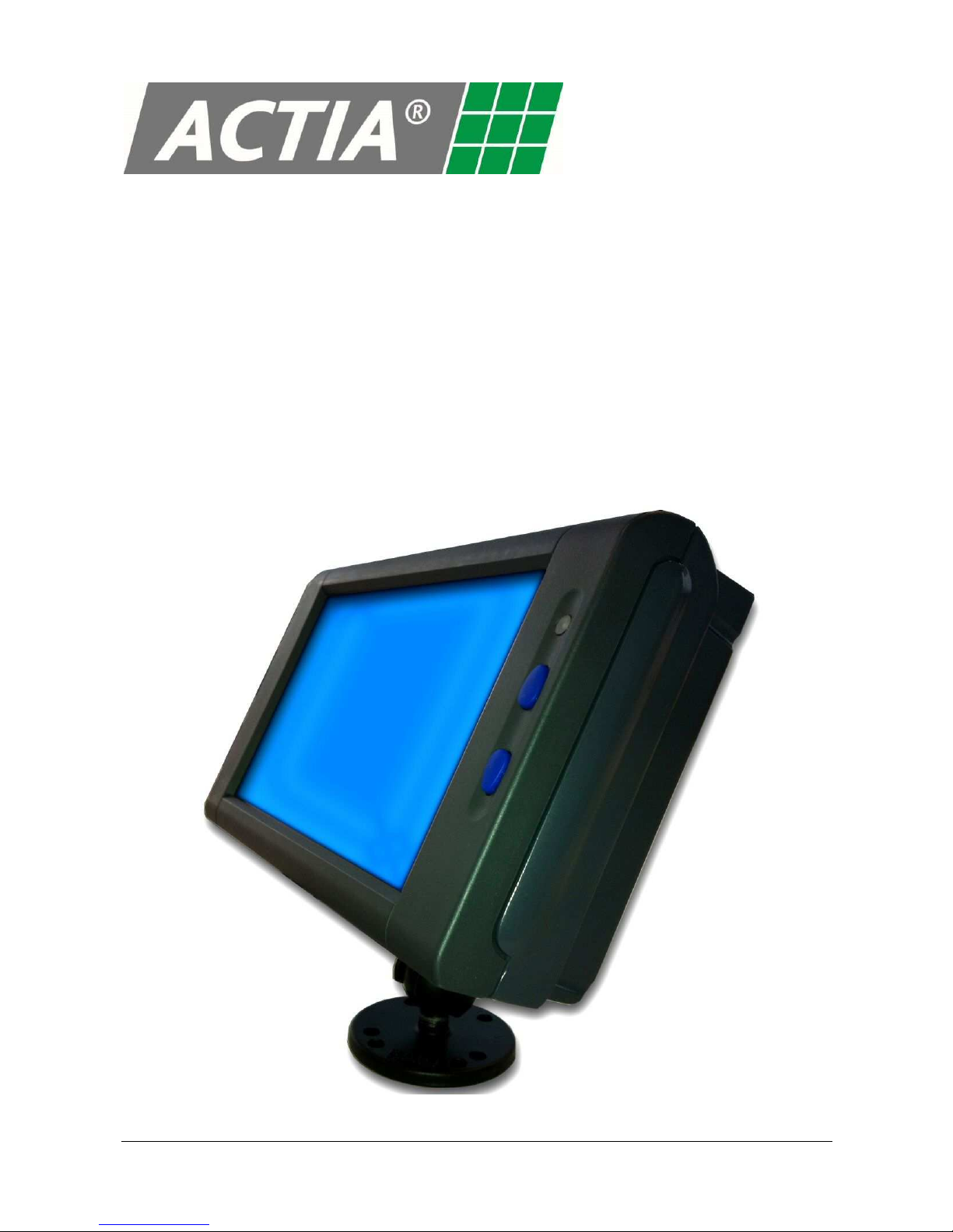
Cover photo : IHMI v2
(Not contractual)
Page 3

DOC 02110-1 ACTIA PCs Page 3 / 52
CONTENTS
DESCRIPTION ................................................................................................................................4
System specifications .........................................................................................................4
General specifications.........................................................................................................4
WARNING .......................................................................................................................................5
FEATURES......................................................................................................................................6
CONNECTORS ...............................................................................................................................7
Connectors location............................................................................................................8
Ethernet...............................................................................................................................9
USB.....................................................................................................................................9
Mixing Panel........................................................................................................................10
Antennas.............................................................................................................................11
CONFIGURATION...........................................................................................................................12
Jumpers ..............................................................................................................................12
BIOS setup..........................................................................................................................13
COMPACT FLASH AND SIM CARD...............................................................................................16
USB interface......................................................................................................................17
CompactFlash interface......................................................................................................17
SIM card holder...................................................................................................................17
LEDS................................................................................................................................................18
System status LED .............................................................................................................18
Ethernet LED.......................................................................................................................18
Reset button........................................................................................................................18
INSTALLATION ...............................................................................................................................19
Cautions..............................................................................................................................19
Antenna cables...................................................................................................................20
Mixing panel and Ethernet cables.......................................................................................20
Cable cover.........................................................................................................................22
Arm Mount ..........................................................................................................................23
Back Cover .........................................................................................................................24
BUTTONS........................................................................................................................................25
Backlight control..................................................................................................................25
System On and Off .............................................................................................................25
POWER MANAGEMENT ................................................................................................................26
System states .....................................................................................................................26
State display........................................................................................................................27
Configuration.......................................................................................................................28
Profiles................................................................................................................................28
Reset button........................................................................................................................28
PROGRAMMING INTERFACES.....................................................................................................29
Inputs/Outputs.....................................................................................................................29
Power Management............................................................................................................30
Specific BIOS functions ......................................................................................................34
OPERATING SYSTEMS .................................................................................................................35
BOOT..................................................................................................................................35
Drivers.................................................................................................................................35
Power Management............................................................................................................35
Inputs/Outputs.....................................................................................................................36
Audio...................................................................................................................................37
CAN.....................................................................................................................................37
CompactFlash preparation tools.........................................................................................37
ELECTRICAL SPECIFICATIONS....................................................................................................39
MAINTENANCE...............................................................................................................................47
Battery replacement............................................................................................................47
APPENDICES..................................................................................................................................48
Mechanical drawings...........................................................................................................48
Product label.......................................................................................................................50
INCIDENT REPORT SHEET...........................................................................................................51
NOTES ............................................................................................................................................52
Page 4

DOC 02110-1 ACTIA PCs Page 4 / 52
DESCRIPTION
IHMI v2
Open embedded solution for onboard vehicle computing and multimedia applications
The IHMI v2 is a compact and cost-effective solution for equipping transport systems. It can be installed in
buses, coaches, or light vehicles.
Based on a PC compatible architecture, the computer is easy to implement. Its innovative mechanical design
and safety system allow fanless operation.
System specifications
This panel is composed of a case, a 7” 800x480 TFT display with LED backlight and a resistive touchscreen.
It also includes an embedded computer based on the Intel BayTrail processor, a GPS and a stereo audio
amplifier with one microphone and two loudspeakers.
The PC architecture is composed of an IHMI-MPC baseboard with an MPC form factor processor board.
System functions are described in the IHMI-MPC user’s manual (DOC02097) and MPC-BayTrail user’s
manual (DOC02106).
This basic system can be equipped with extensions (WiFi, Bluetooth etc.). A dedicated location is provided to
receive a GSM (GPRS/EDGE/2G/3G) optional module.
Optionally, an external Mixing Panel PDB (DOC08024) can also be used with the IHMI v2 in order to add
remote interfaces such as serial com ports, automotive inputs/outputs, CAN Bus, audio Line out/microphone,
etc…
General specifications
Electrical:
12 or 24V power supply voltage (8V to 36V Max)
Computer consumption : 15 W max. with extensions
Environmental:
Operating temperature: -40° / +65°C (*)
Storage temperature: -40 / +85 °C
Relative humidity: 10 to 90% without condensation
Relative humidity: 5 to 95% without condensation (storage)
Dimensions:
Case : 196 x 124 x 57 mm
(*)
- Internal operating temperature is deliberately limited to 85°C, this temperature corresponds to a ca se
temperature of approximately 65°C. Beyond this limit, the internal power supply is turned off to prevent
the system to operate outside the component manufacturers' specifications.
- In similar manner, the power supply is turned off when the internal temperature is less than -40°C.
Page 5
DOC 02110-1 ACTIA PCs Page 5 / 52
WARNING
To prevent fire or shock hazard, do not expose the system to rain or moisture.
To avoid electrical shock, do not open the cabinet. Refer servicing to qualified
personnel only.
Disposal of Old Electrical & Electronic Equipment (Applicable in the
European Union and other European countries with separate
collection systems)
This symbol on the product or on its packaging indicates that this product shall not be treated as household
waste. Instead it shall be handed over to the applicable collection point for recycling of electrical and
electronic equipment. By ensuring this product is disposed of correctly, you will help to prevent potential
negative consequences for the environment and human health, which could otherwise be caused by
inappropriate waste handling of this product. The recycling of matrials will help to conserve natural resources.
For more detailed information about recycling of this product, please contact your local Civic Office or your
household waste disposal service.
Page 6

DOC 02110-1 ACTIA PCs Page 6 / 52
FEATURES
The IHMI v2 is composed with two different boards: The MPC-BayTrail processor board and a IHMI-MPC
baseboard.
The main features are:
- 7” Wide LVD Display 800x480 / Backlight Led with luminosity key control and ambient light sensor
- Restive touch screen (4 wires)
- Intel BayTrail processor board (extended temperature -40 / +85°C) with DDR3L SO-DIMM memory
- Compact Flash Interface
- Automotive power supply input with NF ISO/DIS 7637-1-2-3 protection with ignition input
- Management unit using a Z8 microcontroller for the functions:
o System start / wakeup / stop
o Temperature control
o Dialog with the host via SMBus serial bus
- GPS module with dead reckoning option (internal gyroscope and 2 discrete dedicated inputs for
reverse gear and odometer)
- CAN interface compliant with ISO-11898 24 V up to 1 Mbits/sec
- 3 USB 2.0 interfaces
- Ethernet 10/100/1000 Mbs
- Microphone for GSM and audio system
- Loudspeakers 2x2W
- PCI Express Mini Card interface (USB + PCIe)
- Optional Wifi module (using the PCI Express Mini Card slot)
- Optional GSM/GPRS/3G+ module with SIM card holder
- Optional Bluetooth module
Additional function are provided by the mixing panel. For example with the PDB:
- 4 serial com ports (RS2322/422/485 software configurable)
- 4 protected logical inputs
- 4 logical outputs (relay)
- Audio interface (Line Out, Microphone input)
Page 7
DOC 02110-1 ACTIA PCs Page 7 / 52
CONNECTORS
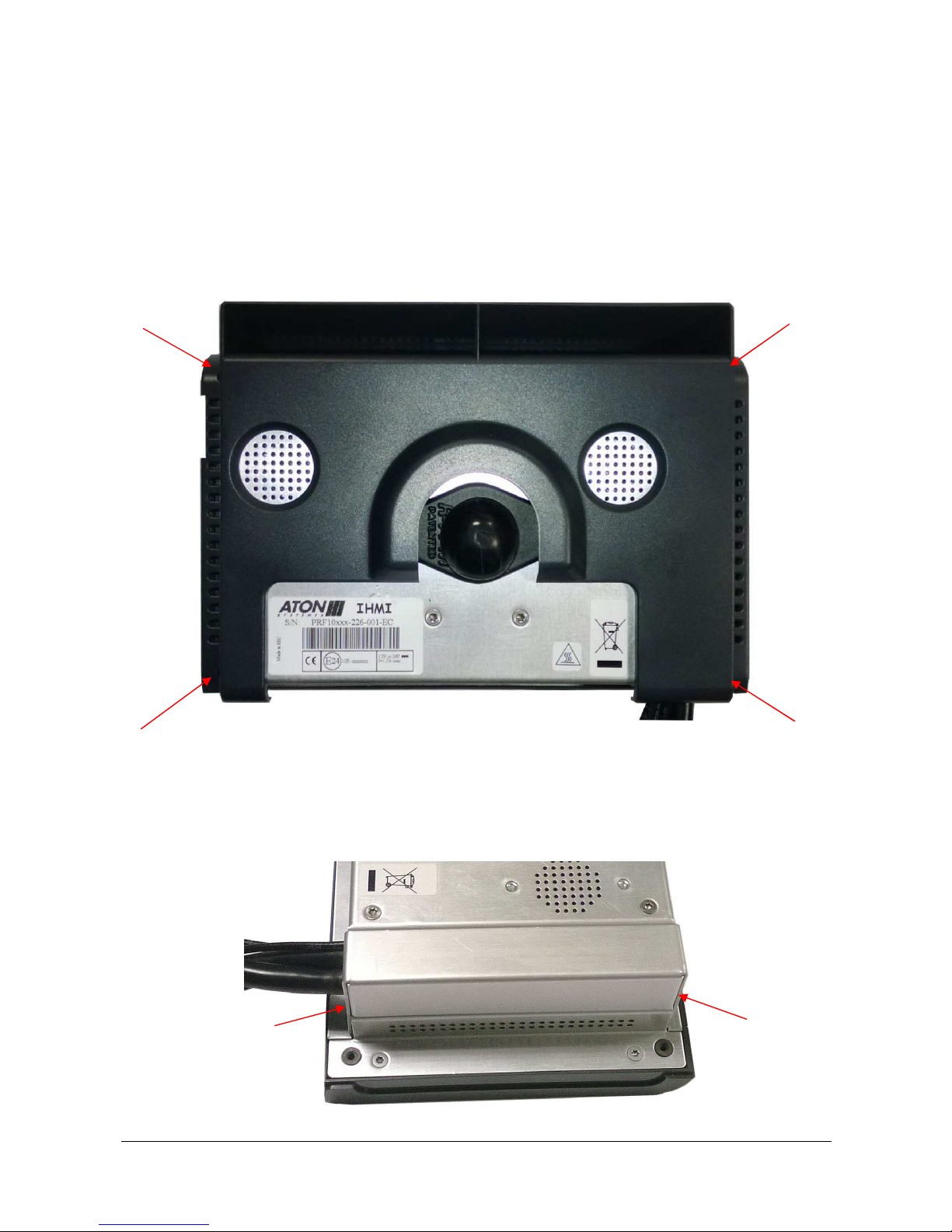
Main connectors outputs are located on the IHMI v2 left panel under a cable cover. In order to access them, it
is necessary to remove the back plastic cover, if present, and the cable metal cover.
To remove the back plastic cover, remove the 4 red arrow marked screws in holes using a Torx 10
screwdriver.
To remove the cable metal cover, remove the 2 red arrow marked screws on the sides using a Torx 8
screwdriver.
Page 8

DOC 02110-1 ACTIA PCs Page 8 / 52
Before unplugging the cables, you must cut the cable ties.
Connectors location
Ethernet 10/100/1000 Base T
USB
Mixing Panel
Jumpers
Internal Speaker Left
Internal Speaker Right
Internal Microphone
Antenna cables
Page 9
DOC 02110-1 ACTIA PCs Page 9 / 52
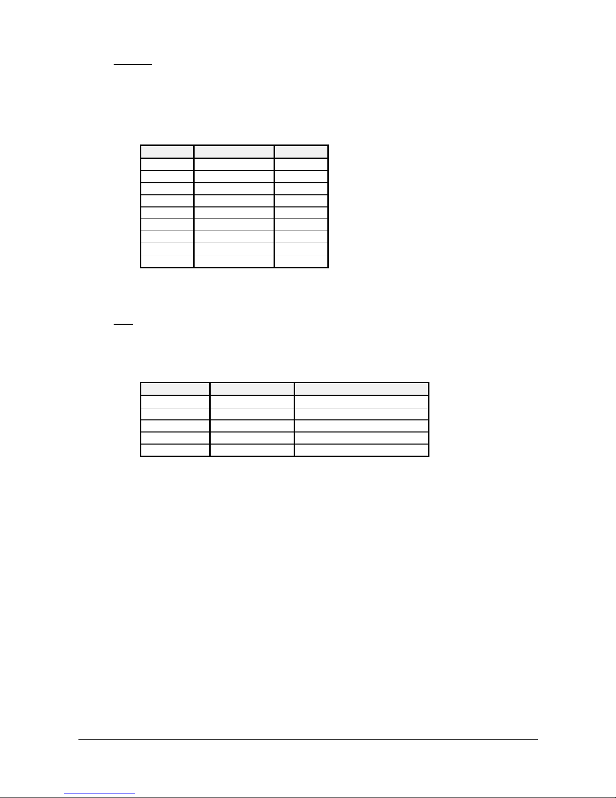
Ethernet
JST BM12B-PUDSS-TFC type
This connector is used to connect an Ethernet 10/100/1000 cable.
Pin Cable* Function
1, 2, 3, 4 Shield Shield
5 Orange MX16 Orange/White MX1+
7 Green MX28 Green/White MX2+
9 Blue/White MX310 Blue MX3+
11 Brown MX412 Brown/White MX4+
* Recommended color
USB
JST BM10B-PUDSS-TFC type
This connector offers a USB interface in addition to the interfaces located on the board.
Pin Designation Function
1, 3, 5, 9, 10 GNDUSB2 Electrical ground (shield, case)
2 USB2- Signal data USB4 USB2+ Signal data USB6 GNDUSB2 Electrical ground
7, 8 VUSB2 USB power supply (max 1A)
Page 10
DOC 02110-1 ACTIA PCs Page 10 / 52
Mixing Panel
JST BM26B-PUDSS-TFC type
This connector offers the power supply, ignition control, logical inputs/outputs, the USB and +5V
power supply for the mixing panel, CAN interface, and specific inputs for dead reckoning GPS
operation.
Pin Designation Function Notes
1,2 VBAT 8 V to 36 V power input External fuse 5AT needed
3, 5, 7, 14, 26 GND Electrical ground
4 IGNITION Ignition information input Active from 5 V to 36 V
6 REVERSE GPS dead reckoning reverse gear input
8 ODOMETER GPS dead reckoning odometer input
9 UBS+ USB To mixing panel
10, 12 VPDB 5V power supply for mixing panel PDB power supply (max 1A)
11 UBS- USB To mixing panel
13 USB shield USB USB Twisted pair shield
15 CANL CAN bus
16 CANH CAN bus
17 IN3 General Purpose Input 3 LVTTL input, (max 3.3V)
18 IN2 General Purpose Input 2 LVTTL input, (max 3.3V)
19 IN1 General Purpose Input 1 LVTTL input, (max 3.3V)
20 IN0 General Purpose Input 0 LVTTL input, (max 3.3V)
21 OUT1 General Purpose Output 1 LVTTL output, max 10mA
22 OUT0 General Purpose Output 0 LVTTL output, max 10mA
23 OUT3 General Purpose Output 3 LVTTL output, max 10mA
24 OUT2 General Purpose Output 2 LVTTL output, max 10mA
25 SHIELD Cable shield
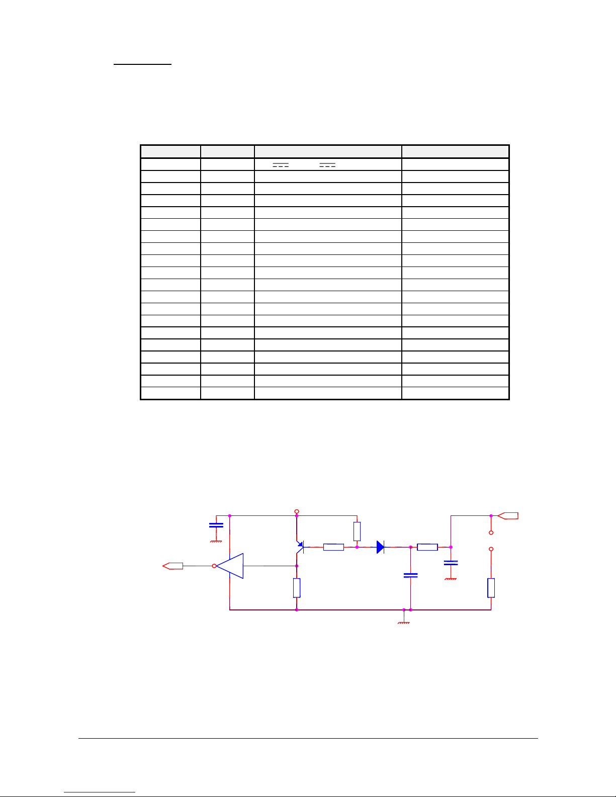
Vehicle Interface discrete input stages
Concerns the following inputs: REVERSE and ODOMETER
By default, detection occurs when the inputs are grounded. A low impedance load connected to
ground is equivalent to grounding of the vehicle interface input.
To detect a positive voltage, the board is equipped with a zone for jumper E26 and E27 (see
CONFIGURATION chapter).
400V diode
10K
Vehicle signal input
100nF
Switch
4K7
To internal logic
10K
470pF
1K
4.7K
+
VCC (Internal +5V)
Page 11

DOC 02110-1 ACTIA PCs Page 11 / 52
Antennas
Depending on available options, FAKRA connectors are used to connect external antennas.
GPS
A Blue FAKRA connector (C code) is used for the GPS receiver.
GSM
A Bordeaux-Violet FAKRA connector (D code) is used for the GSM.
WIFI
A Green FAKRA connector (E code) is used for the Wifi.
Page 12
DOC 02110-1 ACTIA PCs Page 12 / 52
CONFIGURATION
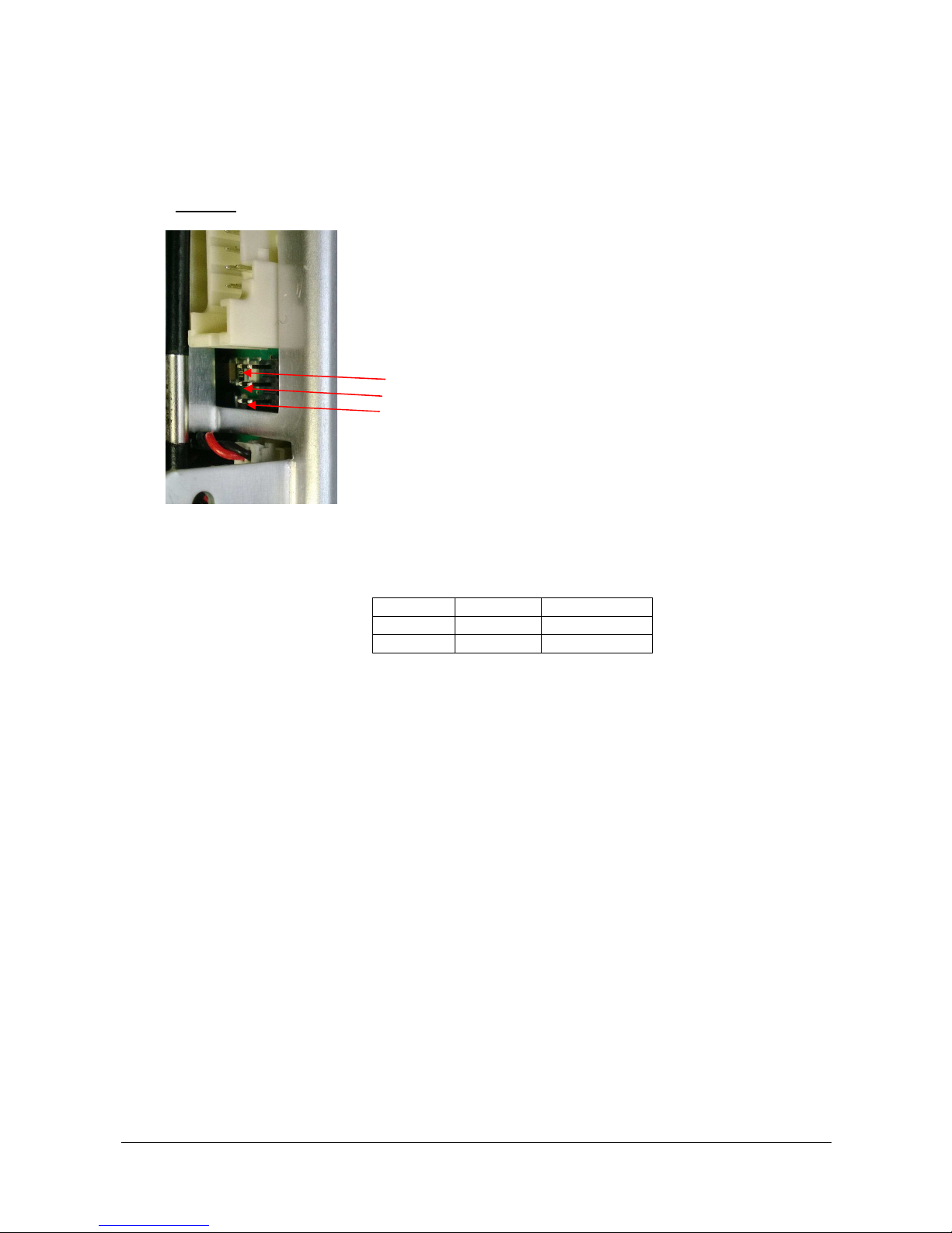
Jumpers
E
E26
E27
E5
E26 and E27 Polarization of REVERSE, ODOMETER inputs when open circuit: By default, jumpers
are not present
Signal REVERSE ODOMETER
Low level E26 = P E27 = P
High level E26 = NP E27 = NP
Low level => signal activation by connection to battery +
High level => signal activation by connection to battery ground
E5 NP No 120 ohm terminator on Interface CAN
P* 120 ohm terminator on Interface CAN
Page 13

DOC 02110-1 ACTIA PCs Page 13 / 52
BIOS setup
As a PC compatible system, the BIOS includes a SETUP utility. An USB keyboard is required to access it.
If the initialization messages are not disabled (Quiet boot : No): SETUP is enabled by pressing the <Del> key
within 3 seconds after the corresponding prompt message or the logo is displayed. If an error is detected on
the POST, the <Del> key enables the SETUP and the <Esc> key is used to continue without SETUP.
If the initialization messages are disabled (Quiet boot : Yes): SETUP is enabled by pressing the <Del> key
within 1 second after the 'System loading …' message or the logo is displayed.
SETUP cannot be entered if its access is locked (locked or absent keyboard, missing or faulty display). It
consists of a menu and dialog boxes. The top part of the screen describes the computer resources. The first
line indicates the title and the last line displays current help on the keys.
If the SETUP parameters are updated, both the CMOS and the E2PROM memories of the processor board
are updated. The E2PROM acts as a backup memory for CMOS and is read by the POST if the CMOS is
faulty.
MAIN MENU
BIOS SETUP
Processor: BayTrail 1333 Version: BIOS PCI-E Rx.x
System Memory: 3002 MBytes Date: xx/xx/xx
+----------------------+
¦Standard Setup ¦
¦Advanced Setup ¦
¦Boot configuration ¦
¦Restore initial values¦
¦Exit without saving ¦
¦Save and Exit ¦
+----------------------+
(c) 1993-2015 ATON Systèmes
←↑→↓ Move cursor [Enter] Select
Esc : Exit SETUP or the current menu
←↑→↓ :
Move the cursor
+- : Modify the current field by increasing or decreasing
Enter ↵ : Activate a submenu
Select the line to be modified by moving the cursor with the arrow keys (←↑→↓)
Change the content by using the +- keys to scroll through the choices or press "Enter" (↵) to display a menu
of available choices.
NOTE: CMOS and E2PROM memories are updated on SETUP exit only if the “Save and Exit” option is
selected.
Standard Setup
+----------------------------------+
¦Date: 04/22/2015 (mm/dd/ccyy) ¦
¦Time: 09:32:52 (hh:mm:ss) ¦
+----------------------------------+
Page 14

DOC 02110-1 ACTIA PCs Page 14 / 52
Date and Time:
Use the arrow keys (
←↑→↓)
to select the field to be modified and press the +- keys to change value.
Return to main menu by pressing "Esc"
Advanced Setup
+---------------------------------+
¦Fast BOOT: Yes ¦
¦Quiet BOOT: Yes ¦
¦ACPI mode: Yes ¦
¦Password: No ¦
+---------------------------------+
Fast Boot: This option disables some tests and reduces the waiting times when initializing the
motherboard.
Example: the memory test is faster, only the size recognition test is maintained; the used memory is
considered to be correct.
Quiet Boot: This option disables error messages and display of banners, in order to mask the PC
style look.
ACPI mode: This option activates the ACPI tables of the MPC-BayTrail board. It also enables the
suspend to ram feature and configures IRQ9 as the ACPI interrupt (SCI).
Password:
+--------+
¦ None ¦
¦ System ¦
¦ Setup ¦
+--------+
The password can be a “system” password of a “setup” password. A “system” password must be entered
each time the system boots. A “setup” must only be given when entering the SETUP or the BOOT menu.
The password must be entered twice, to avoid any typing errors.
Note: the password takes into account the position of the key pressed and not its value (AZERTY or
QWERTY keyboard). The "Shift", "CTR", "ALT", "ALT GR", "Esc" and "Enter" keys are prohibited.
Simultaneous key combinations are prohibited.
Return to main menu by pressing "Esc"
Boot Configuration
It is possible to set the device boot order: None, Sata Disk1, Sata Disk2, USB Storage or CD-Rom. If all boot
devices are set to None, the default boot device will be the first hard disk found.
+------------------------------+
¦ Boot Configuration ¦
¦ First boot device : None ¦
¦ Second boot device : None ¦
¦ Third boot device : None ¦
¦ Fourth boot device : None ¦
¦ [Esc] key : Removable devices¦
+------------------------------+
Page 15

DOC 02110-1 ACTIA PCs Page 15 / 52
First boot device:
+-------------+
¦ None ¦
¦ Sata Disk 1 ¦
¦ Sata Disk 2 ¦
¦ USB Storage ¦
¦ CD-ROM ¦
+-------------+
Choose the device you would like to boot in first.
Second boot device:
Choose the device you would like to boot in second.
Third boot device:
Choose the device you would like to boot in third.
Fourth boot device:
Choose the device you would like to boot in last.
[Esc] key:
+-------------------+
¦ Removable devices ¦
¦ Open Boot menu ¦
¦ No action ¦
+-------------------+
Pressing the “Esc” key during boot process allow the bios to boot from a removable device, open the Boot
menu or No action. Choose the desired “Esc” key action.
Return to main menu by pressing "Esc"
Restore Initial Value
This command is used to restore the displayed data, using the initial values stored in CMOS RAM.
Exit Without Saving
This command is used to exit SETUP without modifying the content of the CMOS RAM.
Save and Exit
This command is used to exit SETUP, saving the modifications in the CMOS RAM.
Page 16
DOC 02110-1 ACTIA PCs Page 16 / 52
COMPACT FLASH AND SIM CARD
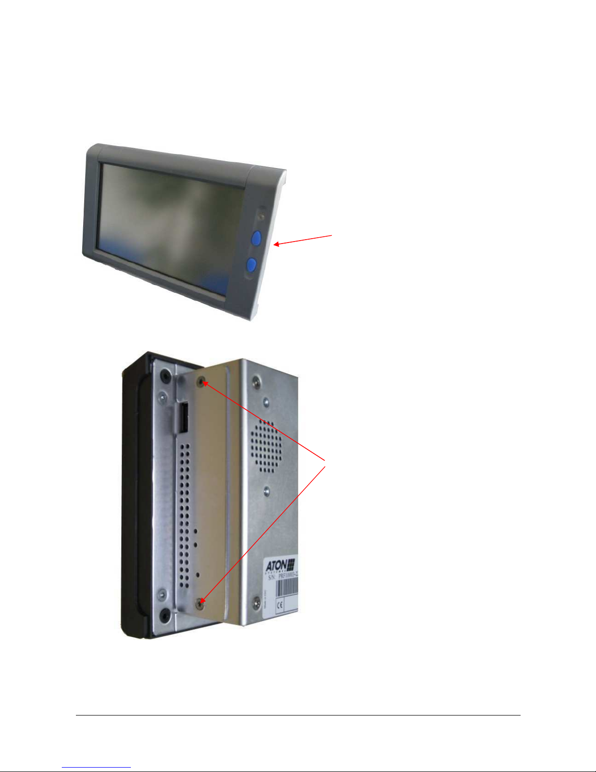
The CompactFlash interface and the SIM card holder are accessed behind a access door on the right panel.
Important: The system must be powered down when loading or unloading any component behind the access
door.
Access door on the right panel
The access door is maintained by 2 screws (tightening of 0.6Nm). Use a Torx 8 screwdriver to remove it.
2 x M2.5x6 Torx screws (countersunk head)
With access door mounted
Page 17
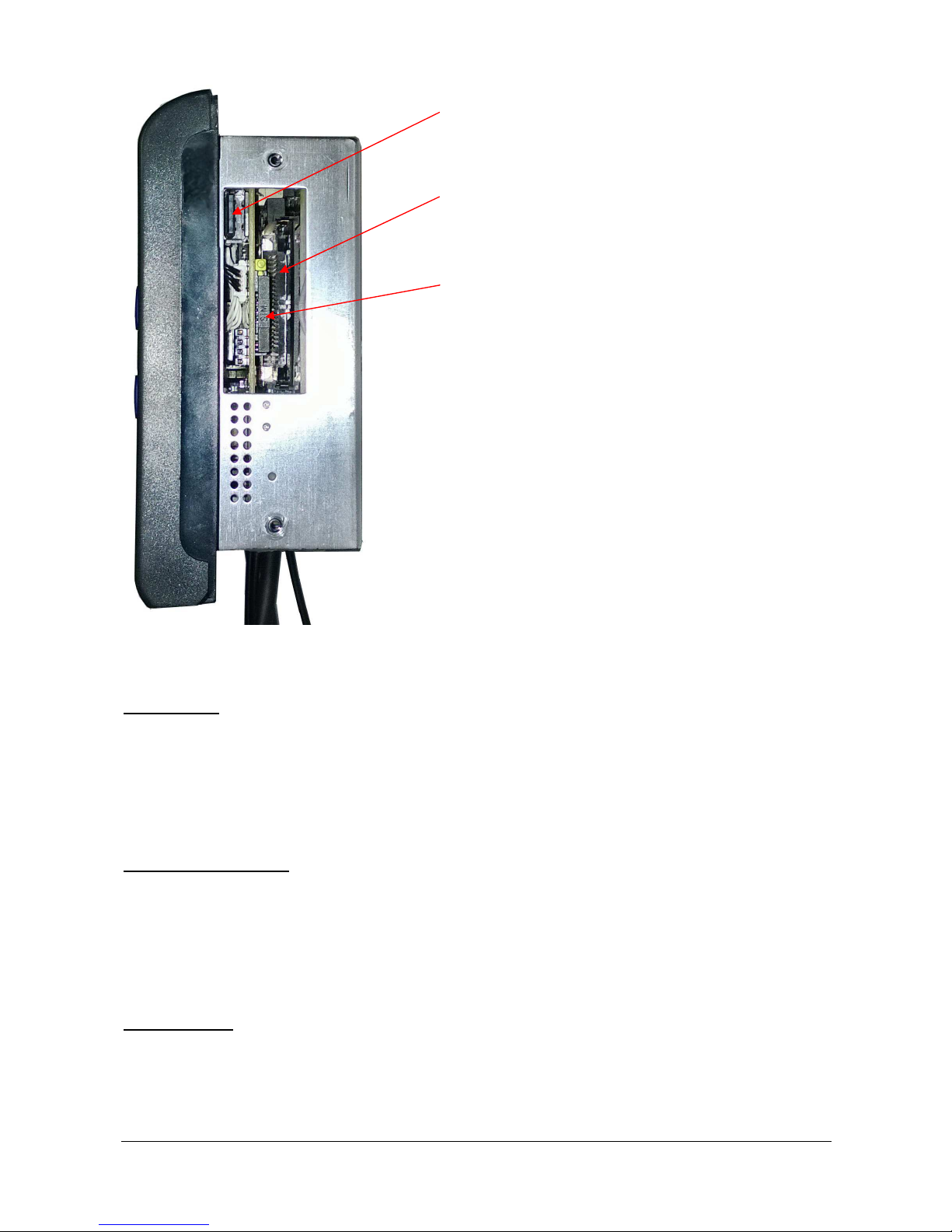
DOC 02110-1 ACTIA PCs Page 17 / 52
USB
CompactFlash
SIM
Without access door
USB interface
USB receptacle A type
This connector is used to connect an USB2.0 or USB1.1 device. It remains accessible when the
access door is mounted.
CompactFlash interface
The CompactFlash interface is accessed behind the access door on the right panel. The access
door is used to lock the CompactFlash. To eject the CompactFlash, press the black button on
the right side of the connector.
Reminder: The system must be powered down when loading or unloading the CompactFlash.
SIM card holder
The SIM card holder is accessed behind the access door on the right panel. To eject the SIM
card holder, press the yellow button on the right side of the connector.
Reminder: The system must be powered down when loading or unloading the SIM card.
Page 18
DOC 02110-1 ACTIA PCs Page 18 / 52
LEDS
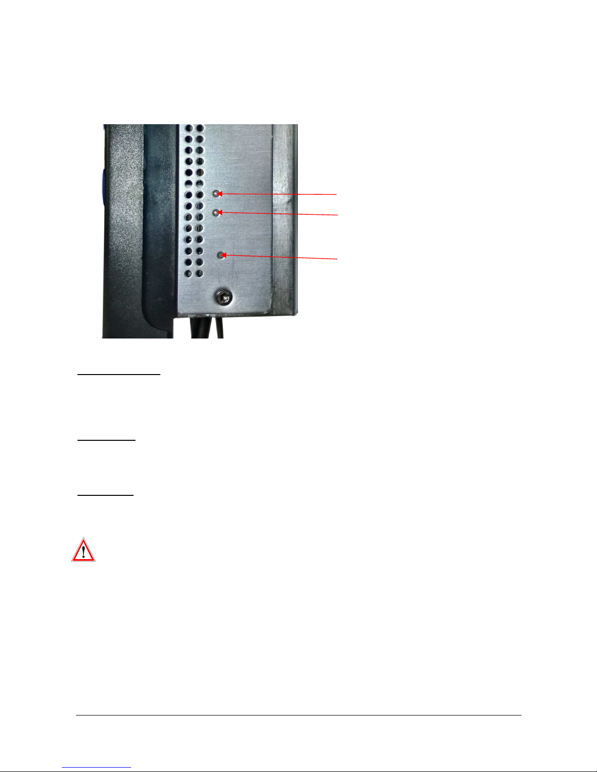
Two LEDs are located behind the access door. They can be seen through holes.
System status LED
Ethernet LED
Reset button
System status LED
The system status LED is controlled by the Z8 microcontroller as described in the power management
chapter.
Ethernet LED
The Ethernet LED represents the MPC-BayTrail Ethernet activity LED.
Reset button
When pressing the reset button with a thin rod through this hole, the power management microcontroller is
restarted. The first effect is to turn off the MPC-BayTrail board.
- Do not introduce a thin rod in a LED hole. It will damage the LED.
Page 19
DOC 02110-1 ACTIA PCs Page 19 / 52
INSTALLATION
Cautions
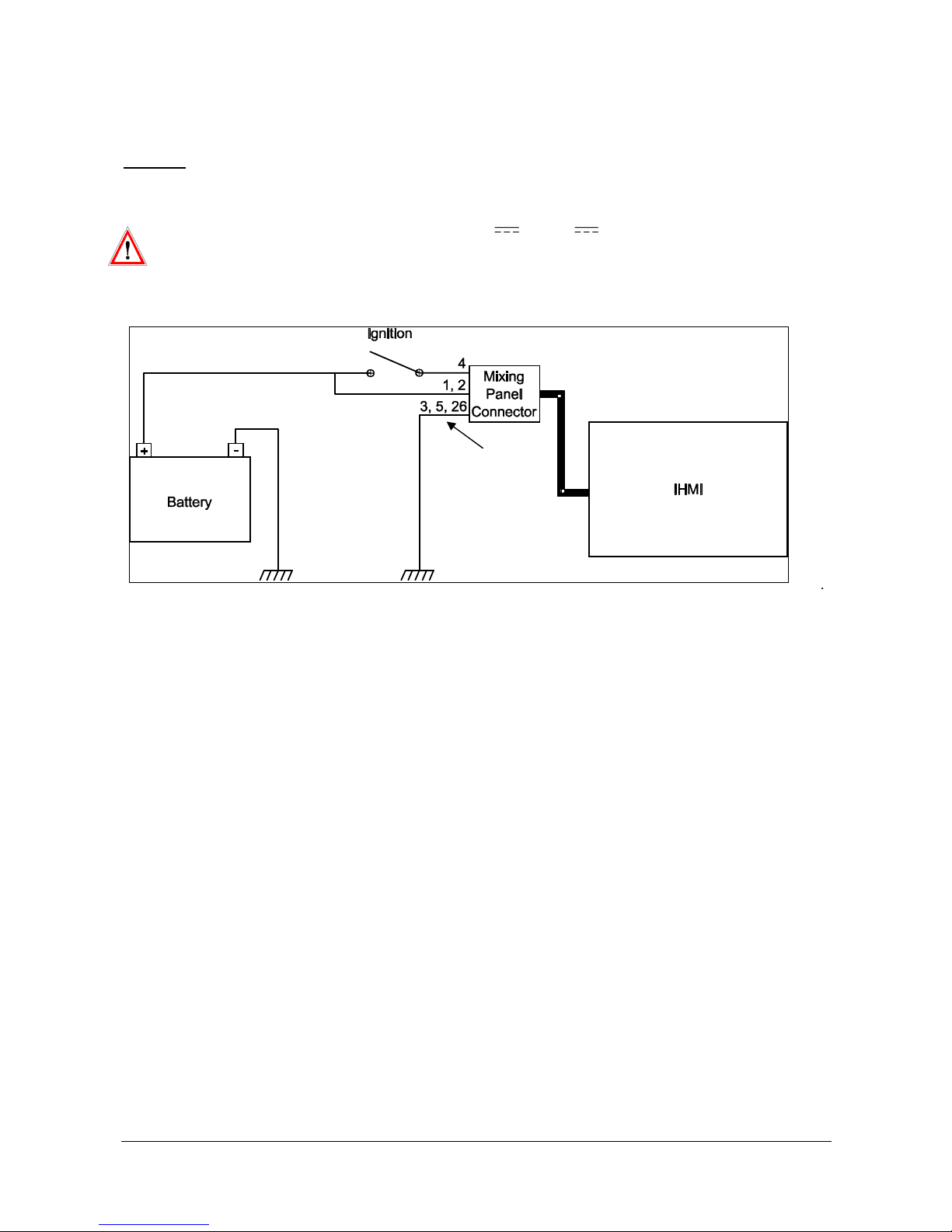
- This system is designed for negative ground 12V or 24V operation only.
- To avoid IHMI v2 damage, remove the battery power before connecting (or disconnecting) the mixing
panel connector. This can be done by removing the PDB fuse.
In this configuration, the IHMI v2 is automatically powered up when the vehicle ignition is switched on. When
the ignition is switched off (for more than 10 seconds), the operating system is notified in order to shut down
properly. After shutdown, the IHMI v2 is powered down.
Note: If the system does not shut down within 10 minutes (standard profile or 45 minutes with aggressive
profile or 4 hours with relax profile) after the ignition was switched off, power down is forced to preserve
battery life.
If IHMI v2 cables are not fully installed, the antenna cables, the mixing panel and Ethernet cables and the
cable cover must be set following the next 3 paragraphs.
Page 20
DOC 02110-1 ACTIA PCs Page 20 / 52
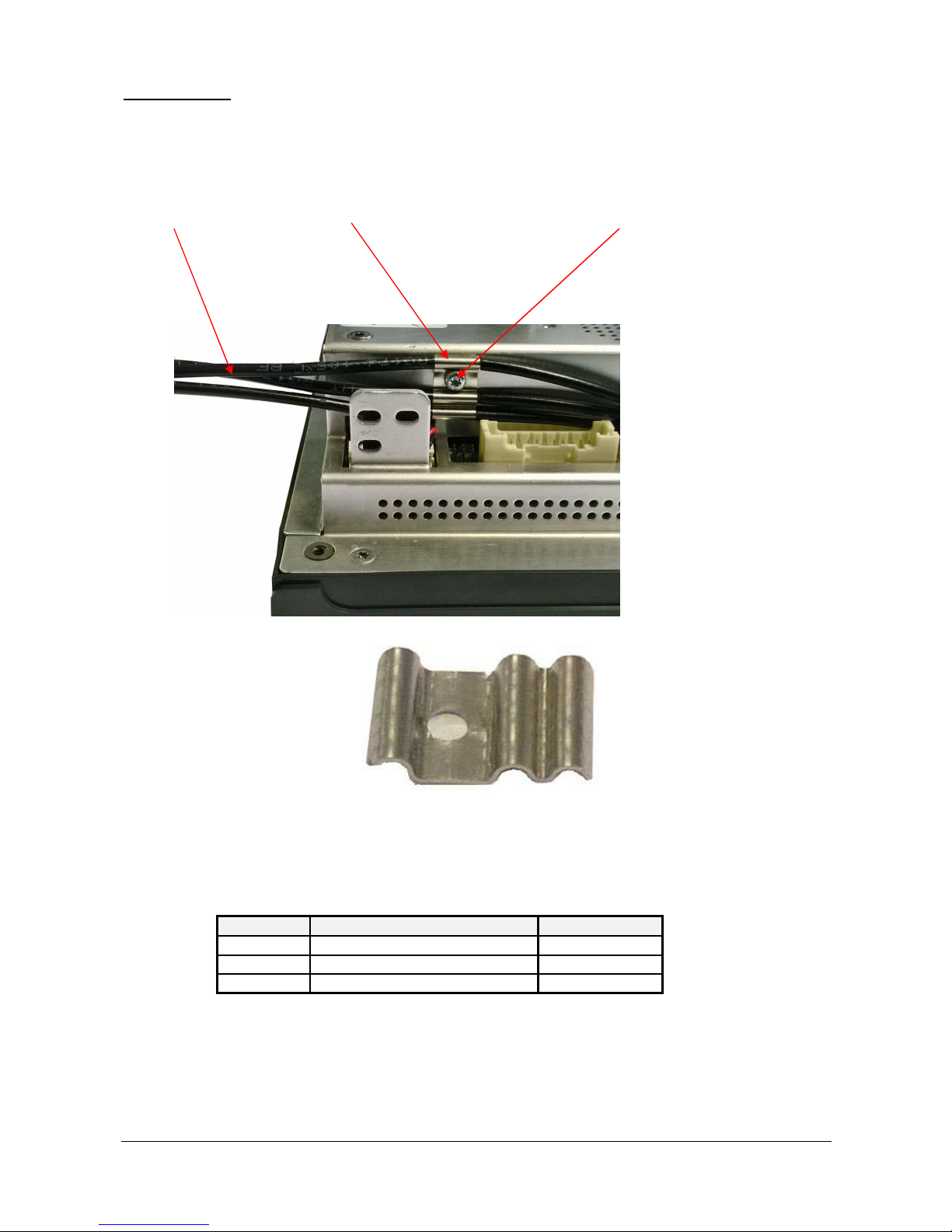
Antenna cables
The GPS, GSM and WiFi antenna cables must be attached to the IHMI v2 housing. They are maintained by a
bridge and a screw (tightening of 0.6Nm). The unsheathed portion of the antenna cables must be located
under the bridge.
Antenna cables Bridge M2.5x6 Torx screw (cylinder head)
Bridge
A multi-function antenna must be mounted on the roof of the vehicle. A separate cable must be installed for
each function. Use the shortest possible length of antenna cable.
Function Antenna Cable connector Cable type
GPS Blue female FAKRA (C code) RG174
GSM Bordeaux-Violet female FAKRA (D code)
RG174
WiFi Green female FAKRA (E code) RG58
Page 21
DOC 02110-1 ACTIA PCs Page 21 / 52
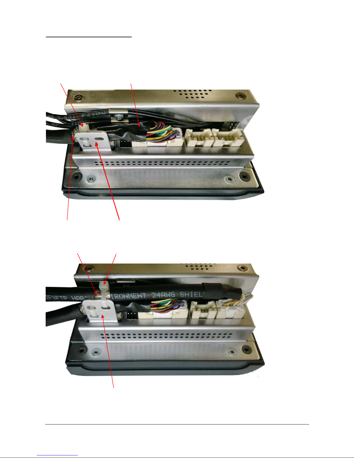
Mixing panel and Ethernet cables
The mixing panel and Ethernet cables must be attached to the dedicated bracket with a cable tie. The
unsheathed portion of the cables must be located on the bracket. If an USB cable is also required, it must be
installed the same way.
First install the mixing panel cable:
Cable tie Mixing panel cable
Unsheathed zone Bracket
Then install the Ethernet cable:
Unsheathed zone Cable tie
Bracket
Page 22
DOC 02110-1 ACTIA PCs Page 22 / 52
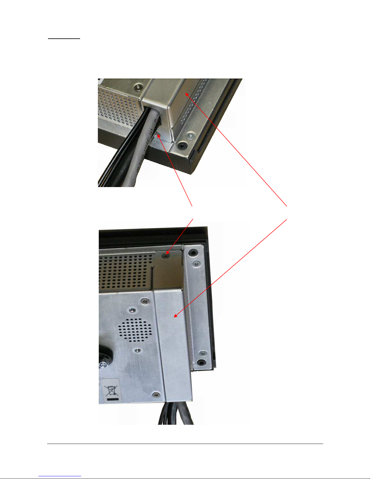
Cable cover
The cable cover must be positioned in such a way that the cables are not pinched by the metal. It is
maintained by 2 screws (tightening of 0.6Nm).
2 x M2.5x6 Torx screws (countersunk head) Cable cover
Page 23
DOC 02110-1 ACTIA PCs Page 23 / 52
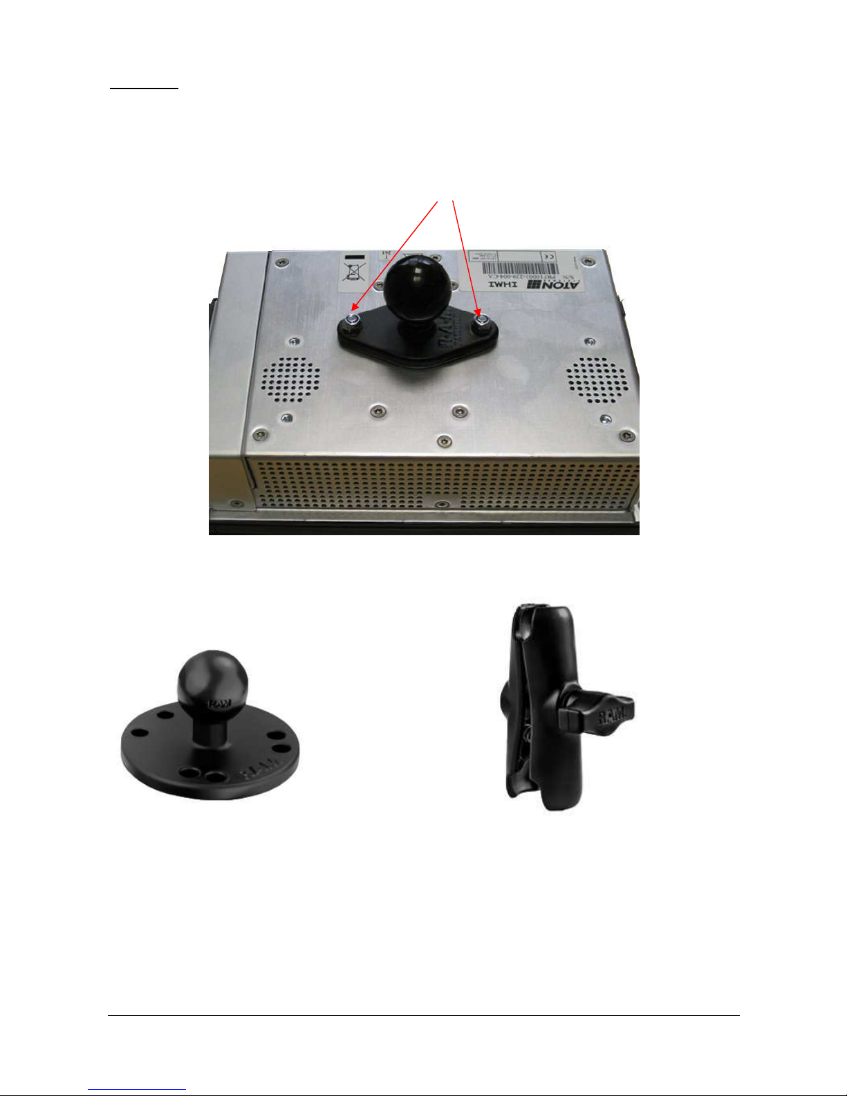
Arm Mount
The arm mount is made of three parts:
- A diamond base with 1” ball,
- A round base with 1” ball,
- A double socket arm.
The diamond base ball is fixed to the IHMI v2 housing witch 2 M4 NYLSTOP nuts (tightening of 1.2Nm).
Round base Double socket arm
Page 24
DOC 02110-1 ACTIA PCs Page 24 / 52
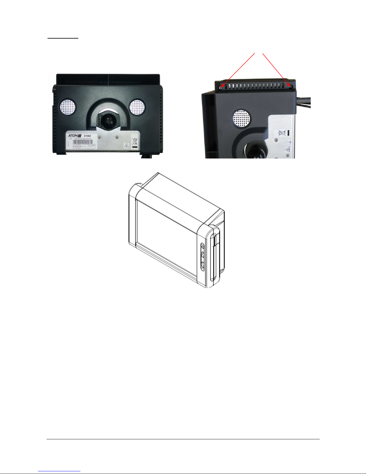
Back Cover
The back cover must be installed after the diamond base ball. It is fixed with 4 panhead plastide M3x10 Torx
screws (tightening of 0.2Nm).
Page 25
DOC 02110-1 ACTIA PCs Page 25 / 52
BUTTONS
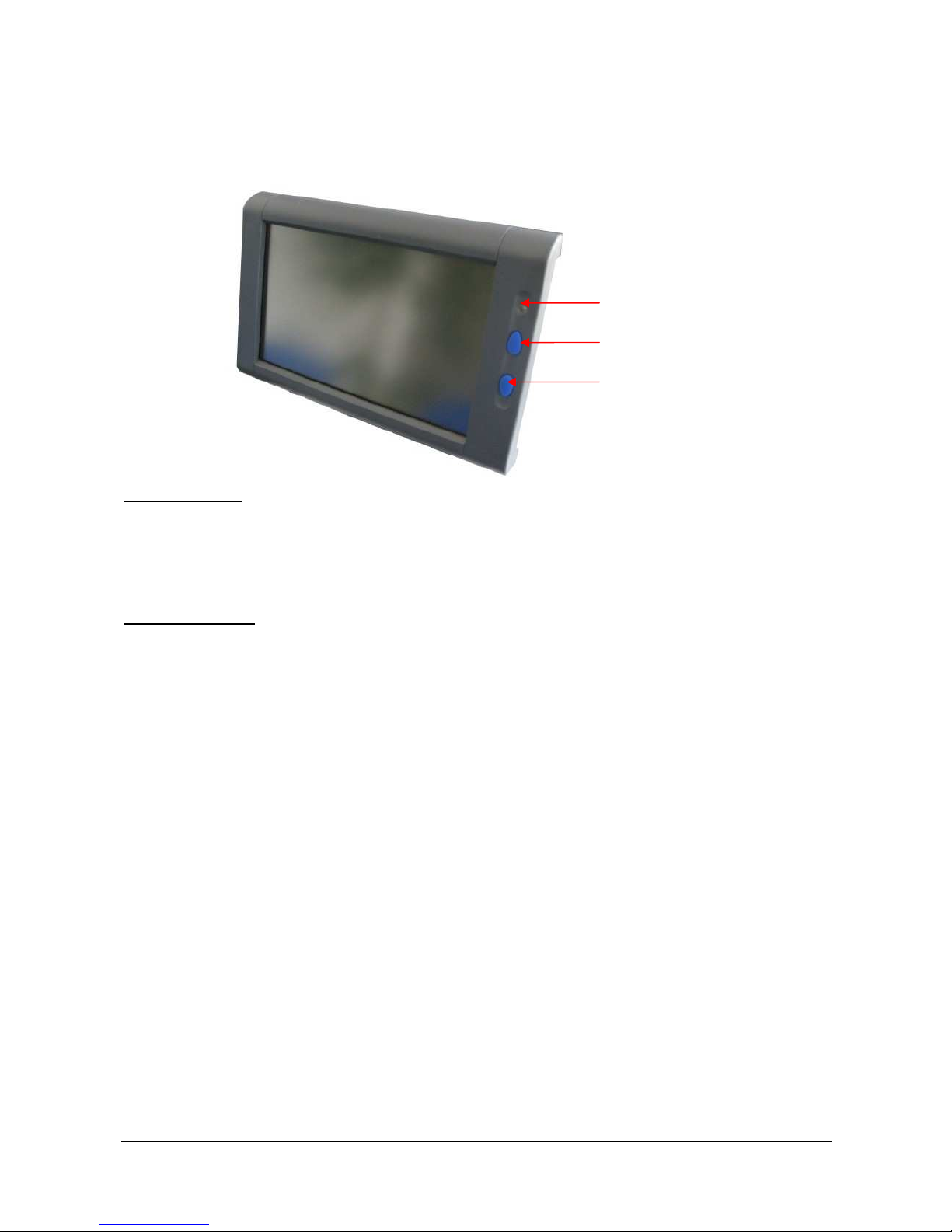
Two buttons are located on the right of the display. They are mainly used to control the backlight intensity.
They can also be used to turn on and off the system.
Light sensor
Increase backlight intensity
Decrease backlight intensity
Backlight control
The backlight intensity level is derived from a light sensor and a dimmer. The dimmer is controlled by the
buttons. Pressing the upper button increases the dimmer while pressing the lower button decreases it. The
dimmer level is maintained when the IHMI v2 is turned off.
System On and Off
Normally the system power is controlled by the ignition signal. However, the IHMI v2 can be configured to not
automatically start when the ignition goes on. In that case, pressing any button during more than half second,
while the ignition signal is on, turns the system on (cf. Z2 in DOC02092).
In the same manner, a system shutdown is requested when the ignition signal goes off. The user can force
this request by pressing the two buttons for more than 2 seconds.
If for some reason, the system is frozen, it is also possible to turned it off by pressing a second time the two
buttons more than 2 seconds. Then it can be restarted by pressing any button during more than half a
second.
Page 26

DOC 02110-1 ACTIA PCs Page 26 / 52
POWER MANAGEMENT
Note: for convenience, part of the IHMI-MPC documentation concerning power management is reproduced
here. This information is not guaranteed. For up-to-date specifications refer to the IHMI-MPC user’s manual
(DOC02097).
The IHMI-MPC board power supply is managed by a Z8 microcontroller. It allows a PC-compatible system to
be adapted to the specific environment of a vehicle.
System startup and shutdown are automatically synchronized with the start and stop of the vehicle engine
(ignition signal turned on and off) whilst allowing the operating system to close properly. The system can also
be woken up by an incoming call from the GSM module or an internal timer. Operation on the vehicle battery
is only allowed for a certain amount of time, to avoid battery draining.
Optionally, system startup when ignition signal turned on can be disabled. In that case the system startup is
requested by pressing a backlight control button.
The internal temperature of the system is monitored to prevent destruction. The system cannot start if the
temperature is too low and it is forced to shut down correctly if the temperature is too high.
In addition, the microcontroller manages the screen backlight level. Two parameters are taken into account:
the level set by the user using the screen buttons and the light sensor. The level is saved in a non volatile
memory in order to be maintained when the system is turned off and on.
Note: following temperatures and delays are specified for the normal profile. A more aggressive profile can be
configured. Those temperatures and delays can also be modified by software (see PROGRAMMING
INTERFACES chapter for details).
System states
State 1: System powered down. The system is in standby state. 2 hours after entering this state, it switches
into very low consumption mode. The LED is then switched off.
The system can only exit this state if ignition signal is switched on (cf. Z2 in DOC02092) or if a backlight
control button is pressed for at least half a second while ignition signal is on. If this temperature is greater
than 70°C when ignition signal is switched on, the system goes directly into state 8. Otherwise the MPC
processor board is switched on and the system goes into state 3. If the power supply did not report a power
good state within one second, the system goes back in state 1 (error 5). The same, if the MPC processor
board did not start (error 1).
Note: The microcontroller could be configured to switch off is own power supply (cf. Z3 in DOC02092) in
order to have a very low standby current. Warning: in that case, data saved in the GPS are lost.
State 2: System powered down with wakeup timer. This state is similar as state 1 with the difference that
the microcontroller could be programmed with a wakeup timer. This timer could be configured from 1 to
65535 seconds or from 1 to 65535 minutes.
State 3: System powered up with ignition signal. The system can remain in this state for an unlimited
period of time.
If ignition signal is switched off for more than 10 seconds, the system goes into state 6. The MPC processor
board manager could request to switch off the power supply (state 1), or to place the board in standby (state
4). The user can request a change to state 6 by pressing simultaneously both backlight control buttons during
al least 2 seconds. It can also be requested by software (see PROGRAMMING INTERFACES chapter for
details).
If the board temperature exceeds +85°C, the IHMI-MPC board requests the MPC processor board manager
to shut down the system and the system goes into state 7.
State 4: System standby. The system goes into this state after a request from the MPC processor board
manager. In this state the MPC processor board switches off all on board power supplies except the memory
(suspend to RAM). This allows a quick startup. The system cannot remain in this state more than 4 hours
while ignition signal is off in order the preserve the vehicle battery.
The system also goes into this state when the MPC processor board turns itself off and GMS and SMBus
wakeup events are enabled. In that case, the wakeup timer controls the maximum time the system can stay
in this state.
Page 27

DOC 02110-1 ACTIA PCs Page 27 / 52
The system exits this state if the ignition signal is switched on (cf. Z2 in DOC02092), a backlight control
button is pressed for at least half a second while ignition signal is on or following a wakeup event. This
wakeup event can be the wakeup timer, a GSM incoming call, a SMBus event or a request from the MPC
processor board itself. If the board temperature exceeds +70°C during a wakeup event, the system goes into
state 9. Otherwise the MPC processor board is switched on and the system goes into sate 3. If the MPC
processor board does not start, the power supply is switched off and the system goes back into state 1 (error
1).
State 5: System powered up after a wakeup. The system cannot remain in this state for more than 30
minutes, to avoid vehicle battery draining. If this time elapses before the operating system shuts down on its
own, the IHMI-MPC board makes a request to the MPC processor board manager to shut down and the
system goes into state 6.
The MPC processor board manager could request to switch off the power supply (state 1), or to place the
board in standby (state 4). The user can request a change to state 6 by pressing simultaneously both
backlight control buttons during al least 2 seconds. It can also be requested by software (see
PROGRAMMING INTERFACES chapter for details).
If ignition signal is switched on, the system goes into state 3. If the board temperature reaches +85°C, the
IHMI-MPC board requests the MPC processor board manager to shut down the system and the system goes
into state 7.
State 6: Waiting for system shutdown. After ignition signal is switched off, if the operation time after a
wakeup is exceeded or at a user or a program request, the MPC processor board manager is requested to
shut down the system through a notification. The IHMI-MPC board waits for the module to turn itself off or to
place itself in standby. The user can force a module power off by pressing simultaneously both backlight
control buttons during al least 2 seconds. It can also be requested by software (see PROGRAMMING
INTERFACES chapter for details).
The system cannot remain in this state for more than 10 minutes (or 4 hours if system startup when ignition
signal turned on is disabled, cf. Z2 in DOC02092). After this delay, the MPC processor board is forced to
switch off and the system returns to state 1 (error 3). As soon as the board temperature reaches +85°C, the
delay is reduced to 2 minutes. If ignition signal is switched on (or switched on again), the system goes (or
returns) into state 3.
Note: upon return to state 3, the fact that a request to shut down the system has been transmitted to the MPC
processor board manager must be taken into account.
State 7: Waiting for shutdown - system too hot. When the board temperature reaches +85°C, the MPC
processor board manager is requested to shut down the system. The IHMI-MPC board waits for module to
turn itself off or to place itself in standby.
The system cannot remain in this state for more than 2 minutes. After this delay, the MPC processor board is
forced to switch off (error 4). At the end of the wait period, the system goes into state 8 (shutdown) or state 9
(standby) if ignition signal is on, otherwise it returns to state 1 (power down) or 4 (standby).
State 8: Waiting for the system to cool down - Power down. The IHMI-MPC board waits until the board
temperature drops down to +75 °C before restarting the MPC processor board. If ignition signal is switched
off, the system goes directly into state 1.
State 9: Waiting for the system to cool down - Standby. The IHMI-MPC board waits until the board
temperature drops down to +75 °C before restarting the MPC processor board. If ignition signal is switched
off, the system goes directly into state 4.
State display
Every 10 seconds, a LED indicates the current system state by flashes of one tenth of a second every one
second. The number of flashes, in a 10 seconds period, is equal to the state number (defined in the previous
paragraph). If there is an error, the error number is displayed instead of the state until the system is restarted.
In this case, the flashes are replaced by half a second hiding.
Page 28
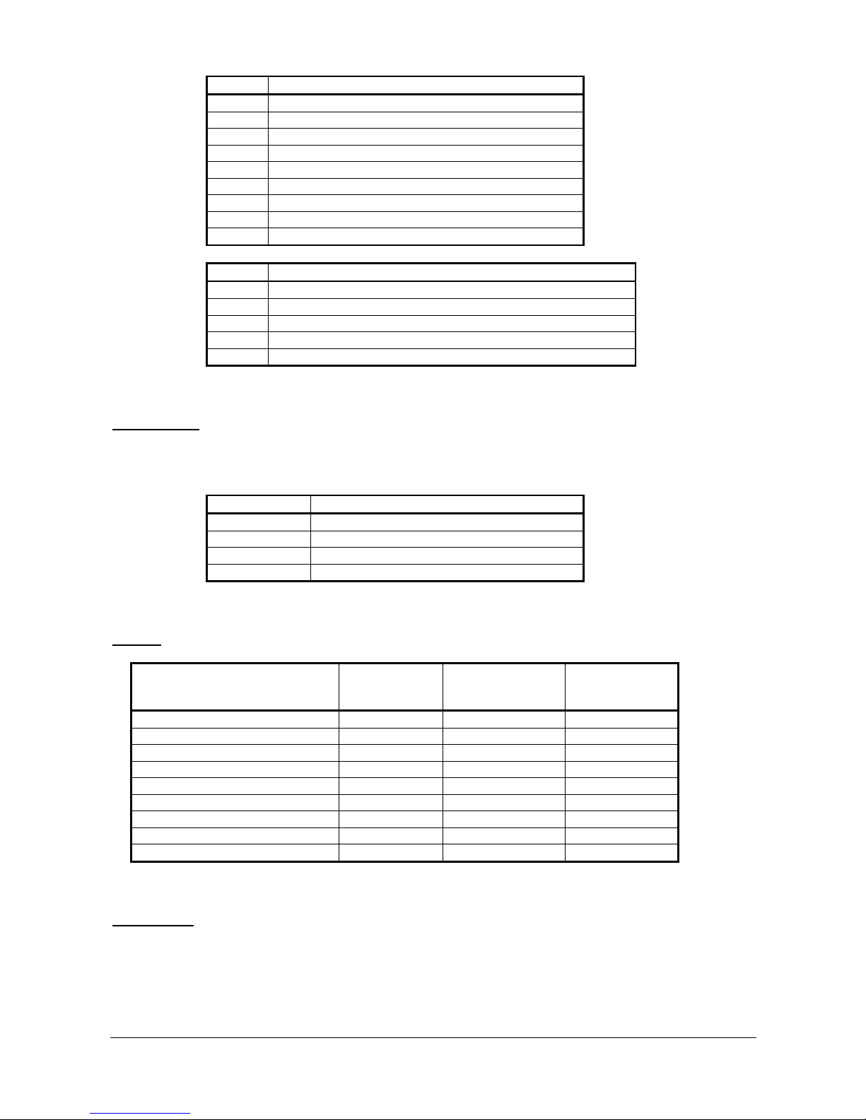
DOC 02110-1 ACTIA PCs Page 28 / 52
State
1 System powered down
2 System powered down with wakeup timer
3 System powered up with ignition signal
4 System standby
5 System powered up after a wakeup
6 Waiting for system shutdown
7 Waiting for shutdown – system too hot
8 Waiting for the system to cool down – power down
9 Waiting for the system to cool down – standby
Error
1 Cannot start MPC processor board after 3 retries
3 System not stopped 10 minutes after the request
4 Too hot system not stopped 2 minutes after the request
5 Power supply not functional
6 Unable to stop the MPC processor
Configuration
The microcontroller configuration is defined during manufacturing through 4 zero Ohm resistors on the IHMIMPC board (cf. DOC02097).
Resistor
Action resistor present
Z1 Select standard profile
Z2 System startup by ignition signal disabled
Z3 Microcontroller power off enabled
Z4 Startup watchdog enabled
Profiles
Parameter
Standard profile
(Z1 present,
Z2 not present)
Aggressive profile
(Z1 not present,
Z2 not preset)
No startup by
ignition signal
(Z2 present)
Startup minimal temperature -45°C -45°C -45°C
Fan on temperature 60°C 60°C 60°C
Startup maximal temperature 70°C 70°C 70°C
Running maximal temperature 85°C 85°C 85°C
Restart minimal temperature 75°C 75°C 75°C
Standby without ignition timeout 240 minutes 240 minutes 240 minutes
Without ignition signal timeout 30 minutes 30 minutes 30 minutes
Shutdown timeout 10 minutes 45 minutes 240 minutes
Too hot timeout 2 minutes 5 minutes 2 minutes
Reset button
Pressing the button reinitializes the power supply management microcontroller. The immediate effect is that
the system goes into power down state (state 1). Transition into another state depends on ignition signal
being on and temperature.
Note: the ignition signal state is taken into account 5 seconds after reset button is pressed.
Page 29
DOC 02110-1 ACTIA PCs Page 29 / 52
PROGRAMMING INTERFACES
Several programming interfaces are provided for the operating system and the application to access IHMI v2
functions. Those functions are connected to various buses or controllers and are driven through different
standard and proprietary programming interfaces.
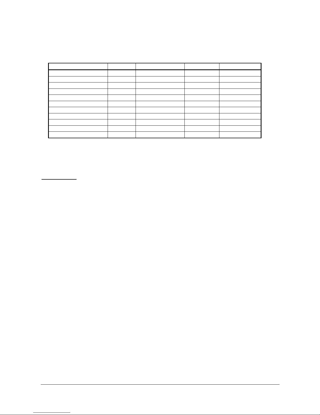
Function
Bus Controller Interface Manufacturer
TFT display Video HD Graphics Intel
Touch Screen USB Touch Screen HID mouse ACTIA PCs
Ethernet PCIe i210 Intel
CAN LPC SJA1000 Philips
WiFi PCIe AR9382 Atheros
GSM USB MC75i/PHS8 Serial port Cinterion
GPS USB NEO-M8 Serial port uBlox
Audio HD-Audio 92HD73E IDT
Inputs/Outputs LPC/USB Proprietary ACTIA PCs
Power Management I2C Proprietary ACTIA PCs
Accelerometer Power Management Proprietary ACTIA PCs
Note: At software level, the LPC bus is equivalent to the standard ISA bus.
Refer to the corresponding documentation for standard or manufacturer specific interfaces. ACTIA PCs
specific interfaces are described here.
Inputs/Outputs
In order to provide compatibility with previous ACTIA PCs embedded computers, logical inputs and logical
outputs of the mixing panel can be accessed through 2 interfaces. Because of those two interfaces, output
states are the logical OR of the corresponding bits. It means that the OUTn relay will be closed if bit n is set to
1 in at least one OUTPUT_REG.
The legacy interface is the vehicle specific interface. It consists of a set of registers in the I/O space of the
ISA bus at base address 0300h.
Output control register
OUTPUT_REG (base+1, W)
- bit 0 : OUT0 output state (0=relay opened, 1=relay closed)
- bit 1 : OUT1 output state (0=relay opened, 1=relay closed)
- bit 2 : OUT2 output state (0=relay opened, 1=relay closed)
- bit 3 : OUT3 output state (0=relay opened, 1=relay closed)
- bits 4 and 5 : not used
- bit 6* : GSM on signal state (0=inactive, 1=active)
- bit 7 : GSM emergency off signal state (0=inactive, 1=active)
*This bit could be used to switch the GSM module on again (ex after AT^SMSO AT command or after an
emergency off). During system power up the GSM is automatically switched on.
Input status register
INPUT_REG (base+2, R)
- bit 0 : IN0 input state (0=low level, 1=high level)
- bit 1 : IN1 input state (0=low level, 1=high level)
- bit 2 : IN2 input state (0=low level, 1=high level)
- bit 3 : IN3 input state (0=low level, 1=high level)
- bits 4 to 7 : not used
The state of bits 0 to 3 reflects the current state of the corresponding input. There is no debouncing circuitry,
so debouncing must be performed by software.
Page 30

DOC 02110-1 ACTIA PCs Page 30 / 52
To access the logical inputs and logical outputs of the mixing panel, Its recommended to use the new
interface through the USB bus. Refer to the documentation of the mixing panel for details.
Power Management
The IHMI v2 power supply is managed by a Z8 microcontroller as described previously. Some parameters
can be modified via the processor SMBus interface.
Z8 microcontroller SMBus address: 6Eh
Register 00h: CONFIG (R)
Bit 0: temperature profile (0=standard, 1= aggressive)
Bit 1: not used
Bit 2: auto power down (0=yes, 1= no)
Bit 3: not used
Bit 7-4: 1111 – see register 1Fh for version
Register 01h: STATE (R/W)
Bits 7-0: current state
1- System powered down
2- System powered down with wakeup timer
3- System powered up with ignition signal
4- System standby
5- System powered up after a wakeup
6- Waiting for system shutdown
7- Waiting for shutdown - system too hot
8- Waiting for the system to cool down – power down
9- Waiting for the system to cool down – standby
Note: Only the values 1 and 6 can be written in this register. Writing 1 requests an immediate power
down of the system. Writing 6 has an effect only when the current state is 3 or 5. It requests an
operating system shutdown.
Register 02h: FILTERED INPUT (R)
Bit 0: NPOE (active at 0)
Bit 1: NCONTACT (active at 0)
Bit 2: NRING (active at 0)
Bit 3: NSMBUSALERT (active at 0)
Bit 4: NS3 (active at 0)
Bit 5: NS4 (active at 0)
Bit 6: NVIN (active at 0)
Bit 7: POWERGOOD (active at 1)
Register 03h: TEMP (R)
Bits 7-0: board temperature °C
Register 04h: VIN (R)
Bits 7-0: board power supply level in 1/5 volt
Register 05h: Not used
Register 06h: LOW_TEMP (R/W)
Bits 7-0: low temperature startup condition °C
Page 31

DOC 02110-1 ACTIA PCs Page 31 / 52
Register 07h: FAN_TEMP (R/W)
Bits 7-0: fan temperature activation °C (not used)
Register 08h: START_TEMP (R/W)
Bits 7-0: max temperature startup condition °C
Register 09h: HIGH_TEMP (R/W)
Bits 7-0: max operating temperature °C
Register 0Ah: HYST_TEMP (R/W)
Bits 7-0: minimal restart temperature °C
Register 0Bh: SUSPEND_OUT (R/W)
Bits 7-0: max delay memory standby without ignition signal in minutes
Register 0Ch: NOCONTACT_OUT (R/W)
Bits 7-0: max delay without ignition signal in minutes
Register 0Dh: SHUTDOWN_OUT (R/W)
Bits 7-0: max delay before power off in minutes
Register 0Eh: TOOHOT_OUT (R/W)
Bits 7-0: max delay system to hot in minutes
Register 0Fh: CONTROL (R/W)
Bit 0: GSM wakeup enable (active at 1)
Bit 1: SMBus wakeup enable (active at 1)
Bits 3-2: not used
Bit 4: wakeup timer unit (0=seconds, 1=minutes)
Bits 7-5: not used
Register 10h: TIMER_LOW (R/W)
Bits 7-0: low byte of wakeup timer in seconds or minutes (cf. CONTROL)
Note: in order to get a consistent value, TIMER_LOW must be read before TIMER_HIGH.
Register 11h: TIMER_HIGH (R/W)
Bits 7-0: high byte of wakeup timer in seconds or minutes (cf. CONTROL)
Note: the wakeup timer is updated when TIMER_HIGH is written. TIMER_LOW must be write
previously. The timer down counting starts as soon as updated.
Register 12h: WAKEUP (R)
Bit 0: GSM wakeup flag
Bit 1: SMBus wakeup flag
Bit 2: not used
Bit 3: first power on flag
Bit 4: timer wakeup flag
Page 32

DOC 02110-1 ACTIA PCs Page 32 / 52
Bit 5: memory standby timeout flag
Bit 6: restart by watchdog flag
Bit 7: not used
Register 13h: BACKLIGHT_LEVEL (R/W)
Bits 7-0: backlight level (01h: min – FEh: max)
Notes:
- This value is stored in the microcontroller flash memory and restored at startup
- Writing 00h disable the backlight, and writing FFh enable the backlight without changing the
backlight level
Register 14h: LIGHT_LEVEL (R)
Bits 7-0: daylight sensor level measured
Register 15h: INPUT_EXT (R)
Bit 0: ODOMETER input level
Bit 1: REVERSE input level
Bit 2: fan turned on flag
Bit 3: fan rotation detection flag
Bits 7-4: not used
Note: This register is not valid on IHMI_MPC boards step A.
Register 16h: ODOMETER_LOW (R)
Bits 7-0: low byte of odometer counter
Note: This register is not valid on IHMI_MPC boards step A.
Register 17h: ODOMETER_HIGH (R)
Bits 7-0: high byte of odometer counter
Note: The high byte of the odometer counter is latched when reading the low byte. So, the low byte
must be read first then the high byte. This register is not valid on IHMI_MPC boards step A.
Register 18h: WATCHDOG (R/W)
Bits 7-0: watchdog counter in seconds
Note: This counter is decremented every second if not equal to zero. When decremented to zero, the
system is powered off. 4 seconds later, the system is powered on. This register can only be written
when the system state is 3 or 5. The watchdog is disabled by writing zero in this register. When
leaving system states 3 and 5, the register is automatically reset to zero. If Z4 resistor is present, the
watchdog register is automatically set to 255 when the system is started (state 3 and 5), otherwise it
remains at zero.
Register 19h: ACCELEROMETER X AXIS (R)
Bits 7-0: X axis acceleration in 1/10 G (-90 to +90)
Register 1Ah: ACCELEROMETER Y AXIS (R)
Bits 7-0: Y axis acceleration in 1/10 G (-90 to +90)
Register 1Bh: ACCELEROMETER Z AXIS (R)
Page 33

DOC 02110-1 ACTIA PCs Page 33 / 52
Bits 7-0: Z axis acceleration in 1/10 G (-90 to +90)
Register 1Fh: VERSION (R)
Bits 7-4: controller type ((0000=EBBPWR2, 0001=EBBPWR3, 00010=IHMIPWR)
Bits 3-0: version number (0000=version A, 0001=version B...)
Register 20h: FLASH_UNLOCK (R/W)
Bits 7-0: flash memory access unlocked if 11011110
Register 21h: FLASH_COMMAND (R/W)
Bits 3-0: number of page to erase (512 bytes page)
Bits 7-4: command (1110=page erase)
Register 22h: FLASH_LOW (R/W)
Bits 7-0: flash memory low part address
Register 23h: FLASH_HIGH (R/W)
Bits 7-0: flash memory high part address
Register 24h: FLASH_DATA (R/W)
Bits 7-0: data corresponding to memory address (registers 22h and 23h)
Note : A new data can be written in flash memory only if the current value is 11111111. A data of
11111111 can only be set by erasing the page containing it.
Page 34

DOC 02110-1 ACTIA PCs Page 34 / 52
Specific BIOS functions
In addition to standard BIOS functions, specific functions are provided.
INT 15h, AH=0E2h - E2PROM Check
Output: AX=E2PROM size in bytes (0 if not available)
BX=first free byte (=reserved bytes count)
INT 15h, AH=0E3h - E2PROM write
Input: BX=byte address
AL=data
Output: AH=0 and CF=0 if OK
AH=86h and CF=1 if address not valid
Note: do not modify reserved bytes.
INT 15h, AH=0E4h - E2PROM read
Input: BX=byte address
Output: AL=data
AH=0 and CF=0 if OK
AH=86h and CF=1 if address not valid
INT 15h, AH=0E9h – SMBus device register byte write
Input: BL=register number
BH=device address (right aligned)
AL=data
Output: AH=0 and CF=0 if OK
AH=86h and CF=1 if not available or error
INT 15h, AH=0EAh – SMBus device register byte read
Input: BL=register number
BH=device address (right aligned)
Output: AL=data
AH=0 and CF=0 if OK
AH=86h and CF=1 if not available or error
INT 15h, AH=0EBh – Boot device presence test
Input: BL=device code
Output: AL=0 if not present, 1 if present, 2 if unknown
AH=0 and CF=0 if OK
AH=86h and CF=1 if not available or error
INT 15h, AH=0ECh – Define boot device for next boot
Input: BL=device code
Output: AH=0 and CF=0 if OK
AH=86h and CF=1 if not available or error
Boot device codes :
1 floppy disk
2 IDE 1 hard disk
3 IDE 2 hard disk
4 SATA 1 hard disk
5 SATA 2 hard disk
6 SATA 3 hard disk
7 SATA 4 hard disk
8 USB storage device
9 CD-ROM
Page 35

DOC 02110-1 ACTIA PCs Page 35 / 52
OPERATING SYSTEMS
The IHMI-MPC board is designed to carry an MPC processor board. ACTIA PCs offers several models of
such boards that deliver various levels of computing power.
MPC processor boards are compatible with standard operating systems such as Windows XP, Windows
XPe, Windows 7 and Linux. As a result, the IHMI-MPC board, combined with an MPC processor board, is
able to support any PC standard software as well as customer application running on standard PC.
BOOT
The boot device selection is configured using the SETUP, but it can be override by pressing the Esc key
when booting or by calling a dedicated BIOS function.
STANDARD BOOT: if no boot device is configured in the SETUP, the operating system is booted from the
first disk found starting with the primary master IDE interface then the primary slave IDE interface.
BOOT with PRIORITY ORDER: if at less one boot device is configured in the SETUP, a boot is tried from
each device in the specified order.
BOOT from REMOVABLE DEVICE: if this feature is enabled in the SETUP, pressing the Esc key just before
the operating system loading conducts the BIOS to try to from a CD-ROM and, if it doesn’t succeed, from a
USB storage device.
Remark: An USB hub can be used to connect together a keyboard and a removable device to the standard
USB connector.
BOOT DEVICE SELECTION menu: if this feature is enabled in the SETUP, pressing the Esc key just before
the operating system loading activates the boot device selection menu. Only the detected devices and those
that could be there are displayed.
BOOT DEVICE SELECTION by SOFTWARE: the INT 15H, AH=0ECh function can be use to specify the boot
device for the next boot and only the next one. This feature is specially suited to a “Boot manager” software
installed on the SETUP configured boot device. It can decide, using specific rules, to boot the operating
system from an alternate device.
NOTE: a boot try fails if the boot sector can’t be read, if its contents is invalid or if the loader executes INT
18h.
Drivers
Operating systems require specific drivers for some devices. Because the IHMI-MPC board and the MPC
processor boards developed by ACTIA PCs are build around standard devices, the corresponding drivers are
fully available on the Word Wide Web. However, in order to help the customer, drivers for Microsoft operating
systems are directly available on ACTIA PCs website (www.actia-pcs.fr).
ACTIA PCs provides a large support on Windows CE (WEC). Binary Support Packages (BSP) are available
for last versions of this operating system, as well as a large set of drivers, application samples and
development tools.
The Linux community is very active. It is better to look for last versions of software on dedicated websites.
Power Management
As described in the POWER MANAGEMENT chapter, the IHMI-MPC power controller requires some
contribution from the operating system. In order to support smooth operating system shutdown, it is
mandatory that some piece of software informs the controller when it is safe to turn off the power. On the
other hand, the IHMI-MPC power controller notifies the operating system when ignition is switched off. Two
means are proposed with the IHMI-MPC to perform this dialog.
Page 36
DOC 02110-1 ACTIA PCs Page 36 / 52
-The IHMI-MPC power controller constantly monitor power control signal coming form the power controller of
the MPC processor board. This controller is usually accessed by the operating system through the
standardized ACPI interface. Some operating systems such as Windows XP, Windows XPe, Windows 7 and
Windows 8 natively support the ACPI interface.
Note: the ACPI mode must be enabled in the SETUP of the processor board.
-A proprietary interface can be accessed by software to implement the dialog with the IHMI-MPC power
controller. Refer to the PROGRAMMING INTERFACE chapter for detailed information.
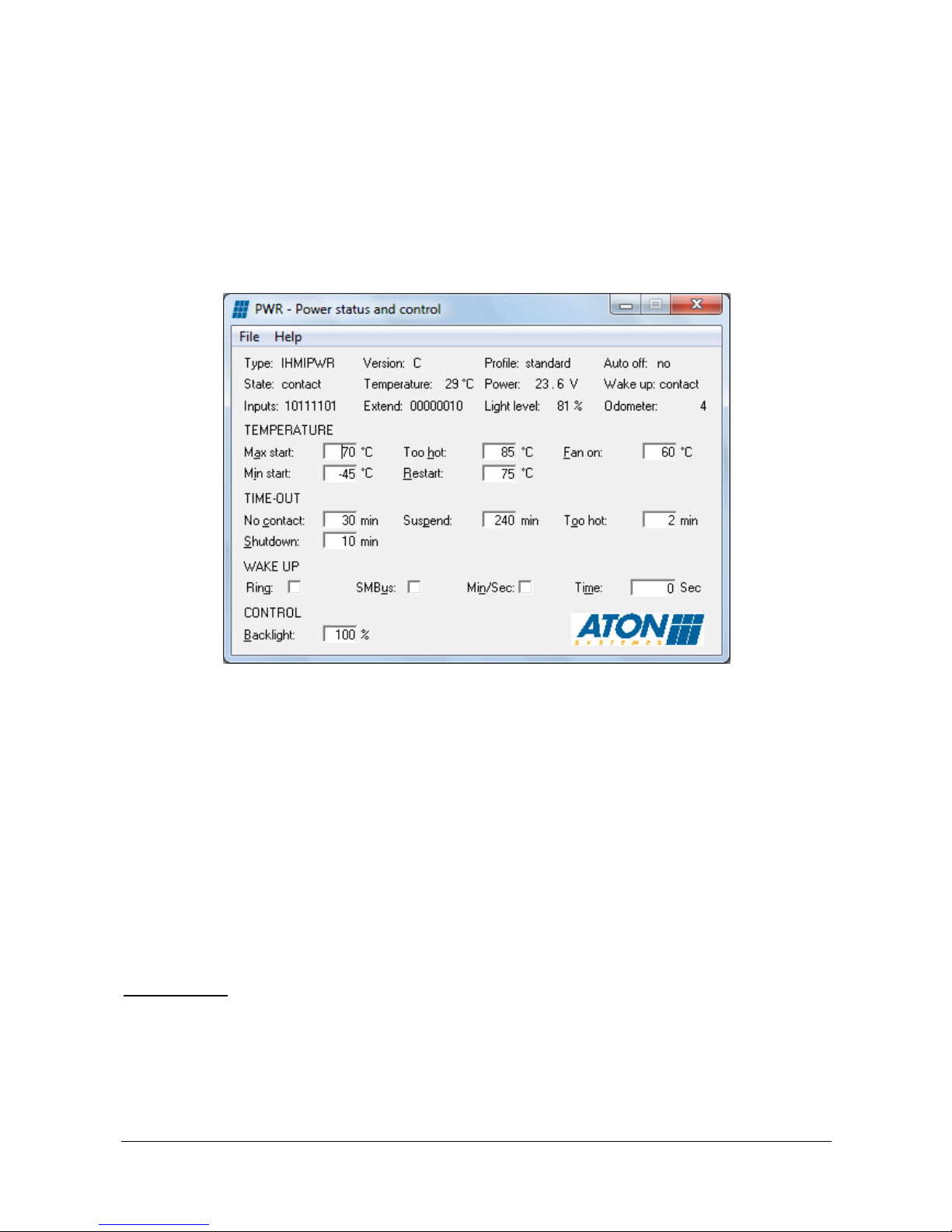
A SMBus driver (SCHSMBUS.SYS) is available for Windows XP, Windows XPe, Windows 7 and Windows 8.
The PWR.EXE utility demonstrates how this interface can be used.
The operating system can be configured to shutdown or to go to standby mode when the ignition signal is
switched off. Under Windows, this parameter is named “When I press the power button on my computer” in
the “Power options” of the “Configuration panel”.
- If the selected action is “Shut down” and the ignition signal is switched off, the IHMI v2 goes to the power
down mode (state 1) at the end of the operating system shutdown. In this state, the vehicle battery power can
be removed. When the ignition signal is switched back on, the operating system reboots.
- If the selected action is “Standby”, the IHMI v2 goes to the standby mode (state 4) when the ignition signal is
switched off. All the state of the system is saved in the DRAM of the MPC board. In this state, the vehicle
battery power must NOT be removed. When the ignition signal is switched back on or after 4 hours, the IHMI
v2 returns to the running mode very quickly.
When leaving the standby state, the application must check the wakeup reason. If it is because the 4 hours
delay is exhausted, the application must force an operating system shutdown. This mechanism must be
implemented in order to avoid vehicle battery draining.
Inputs/Outputs
The legacy vehicle specific interface can be accessed under Windows XP, Windows XPe, Windows 7 and
Windows 8 through the MPC.SYS driver. The MPCTEST.EXE utility can be used to view the state of the
inputs and modify the outputs of the mixing panel.
Page 37
DOC 02110-1 ACTIA PCs Page 37 / 52
When the logical inputs and logical outputs of the mixing panel are accessed through the USB bus, the
PDBTEST.EXE utility can be used to view the state of the inputs and modify the outputs. No specific driver is
required.
Audio
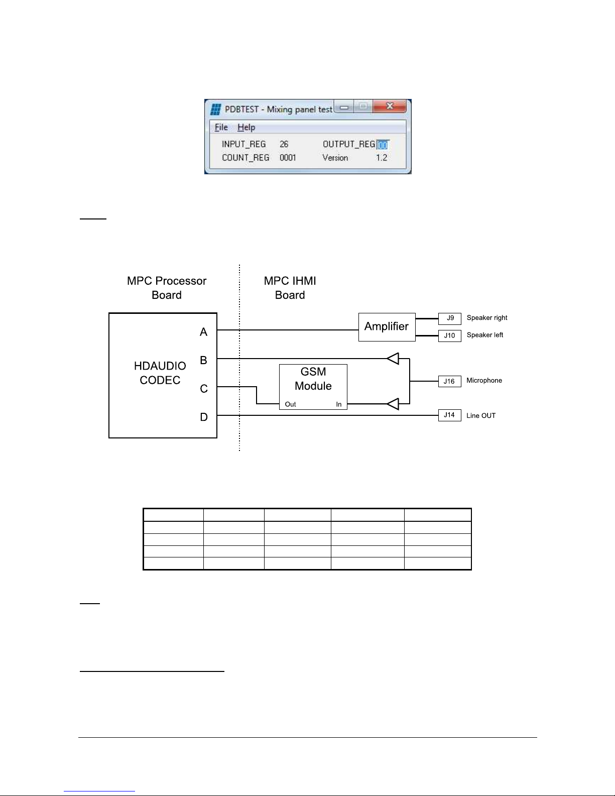
The AUDIO interfaces are described in the diagram below. They are connected to the MPC processor board
to the HDAUDIO codec interface.
Standard HD audio drivers automatically configure the audio codec. The following table gives the connection
between audio channels of the IHMI v2 and the common designation based on plug type, plug location and
plug color.
Channel
Function Plug Type Plus Location Plug Color
A HP-OUT Jack Front Green
B MIC-IN Jack Front Pink
C LINE-IN Jack Rear Blue
D LINE-OUT Jack Rear Green
CAN
ACTIA PCs developed Windows CE and Windows XP drivers for the SJA1000 controller. Test utilities are
also available.
CompactFlash preparation tools
The preferred IHMI v2 system disk is a CompactFlash. However it is not easy to install an operating system
on it. In addition software development is usually done on a desktop PC. It is why ACTIA PCs has developed
a set of tools and procedures to help the customer in this job. Using a desktop PC running Windows XP,
Page 38

DOC 02110-1 ACTIA PCs Page 38 / 52
Windows 7 or Windows 8 and a CompactFlash card reader (USB), it is possible to prepare or duplicate
CompactFlash that boot on an IHMI v2.
Those tools and procedures are available on ACTIA PCs website (www.actia-pcs.fr).
Page 39

DOC 02110-1 ACTIA PCs Page 39 / 52
ELECTRICAL SPECIFICATIONS
Battery power Input (Pin 1 and 2 of J20 – GND return through pin 3, 5 and 26 of J20):
Voltage: 8 V to 36 V
Current: maximum 2.5 A (protection by 5 A external fuse is mixing panel not used)
Protections: polarity inversions and interference (Standards ISO 7637)
Filtering: EMC
Ignition input (Pin 4 of J20):
Voltage: -24 V to 100 V
Input resistance: 10 k (current less than 10 mA)
Active: greater than 5 V
Inactive: less than 1 V
Internal power supply (Pin 10 and 12 of J20)
Voltages: 5 V +/-5%
Maximum current 1A
Logical REVERSE and ODOMETER (Pin 6 and 8 of J20):
Maximum voltage (without polarization jumper): -50 V to 100 V
Maximum voltage (with polarization jumper): -34 V to +34 V
Input resistance (without polarization jumper): 10 k
Input resistance (with polarization jumper): 3.2 k
Active: greater than 4.5 V
Inactive: less than 3 V
Maximum odometer frequency: 2KHz
Logical Inputs (Pin 17 to 20 of J20):
LVTTL 3.3V inputs (Embedded 10K pull down)
Logical Outputs (Pin 21 to 23 of J20):
LVTTL 3V3 10mA
CAN Bus interface (Pin 15 and 16 of J20):
CAN2.0b Pelican
Bus driver : 82C251
Microphone input (J16):
Power supply: 5 V +/-5%
Maximum peak to peak voltage: 0.5 V
Input resistance: 2.2 k
Audio outputs (J14):
Minimum RMS voltage at full scale: 1 V
Passband on 10 k: 20 Hz to 20 kHz
Audio amplifier (J9 and J10):
2x2W @ 4 ohms
2x1W @ 8 ohms
Page 40
DOC 02110-1 ACTIA PCs Page 40 / 52
USB interface (J19):
Power supply: 5 V +/-5%
Maximum power supply current: 500 mA
Signal maximum current: 50 mA
Electrostatic protection: 15 kV
USB 2 interface (J21):
Power supply: 5 V +/-5%
Maximum power supply current: 1000 mA
Signal maximum current: 50 mA
Electrostatic protection: 15 kV
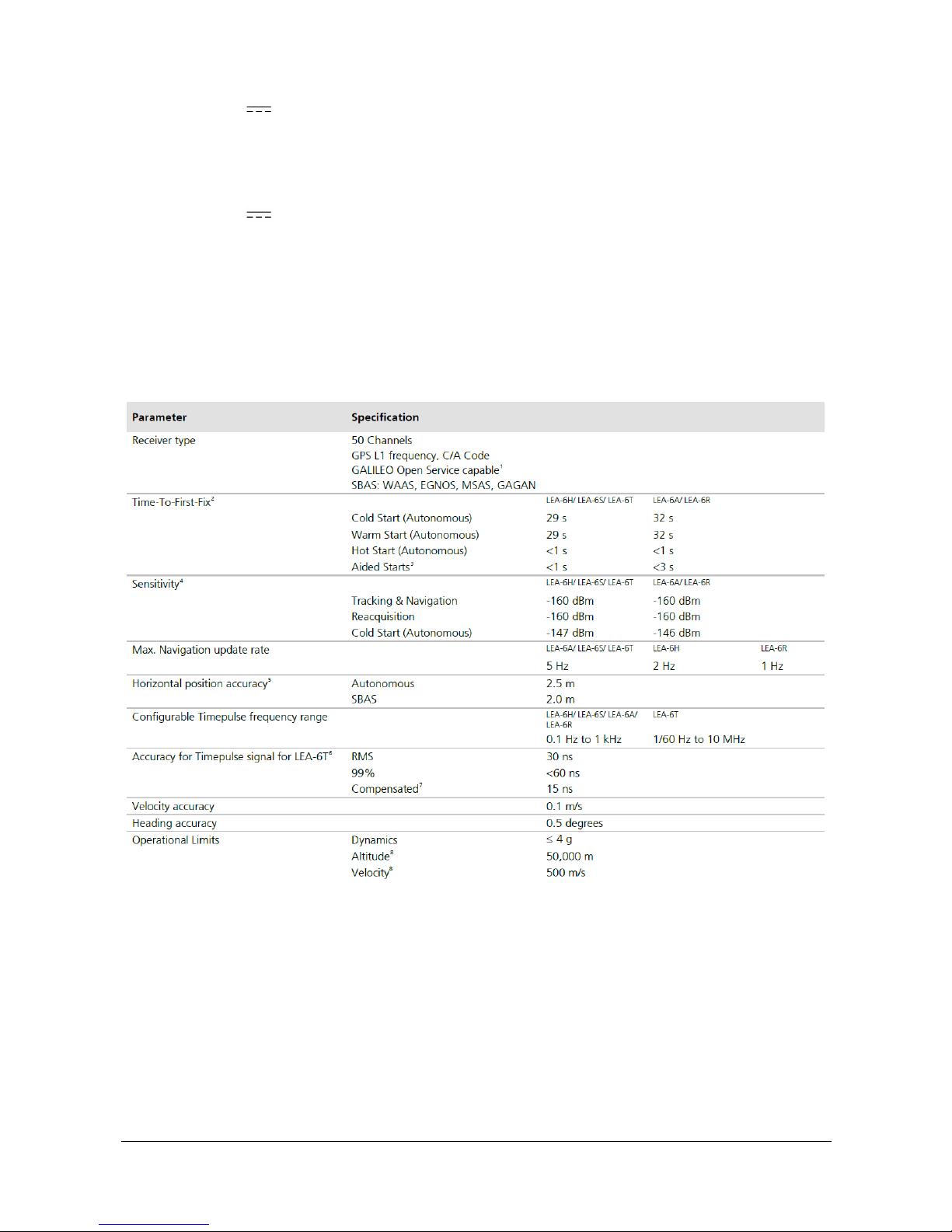
GPS
Antenna type: Fakra C code (Blue) passive or active
Antenna impedance: 50 ohms
Active antenna recommendations: minimum gain 15dB / maximum gain 50dB / 3.3V 50mA
Module: u-blox LEA-6R
Page 41
DOC 02110-1 ACTIA PCs Page 41 / 52
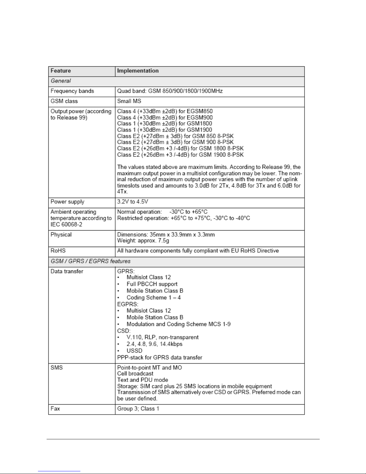
GSM (Optional)
Antenna type: Fakra D code (Bordeaux-violet) passive or active
Antenna impedance: 50 ohms
Module MC75i (EDGE World) 1/2
Page 42
DOC 02110-1 ACTIA PCs Page 42 / 52
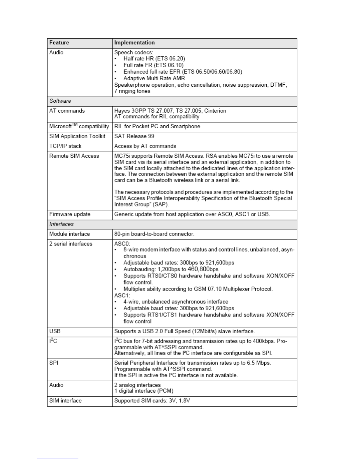
Module MC75i (EDGE World) 2/2
Page 43
DOC 02110-1 ACTIA PCs Page 43 / 52
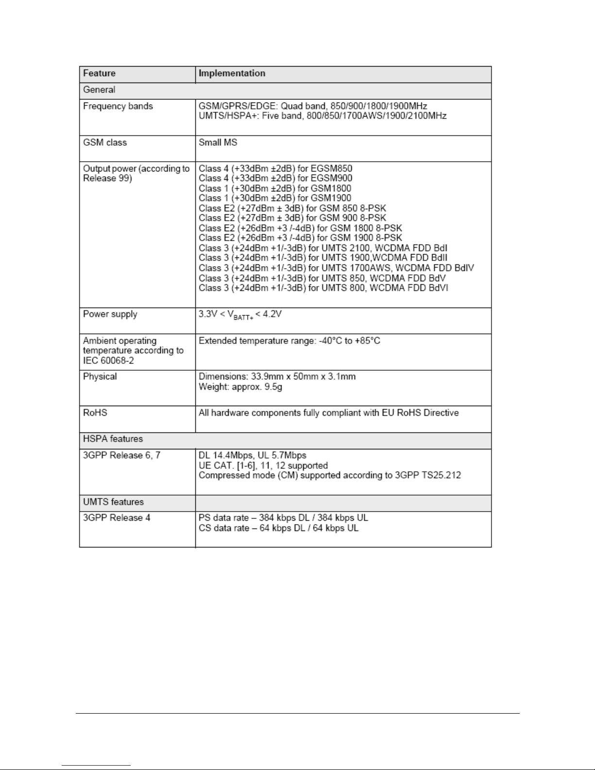
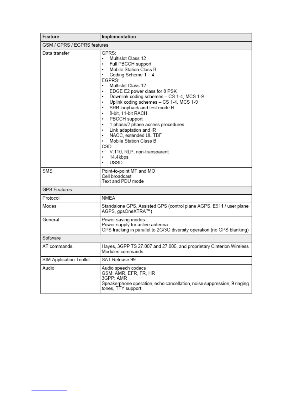
Module PHS8 (3G World) 1/2
Page 44
DOC 02110-1 ACTIA PCs Page 44 / 52
Module PHS8 (3G World) 2/2
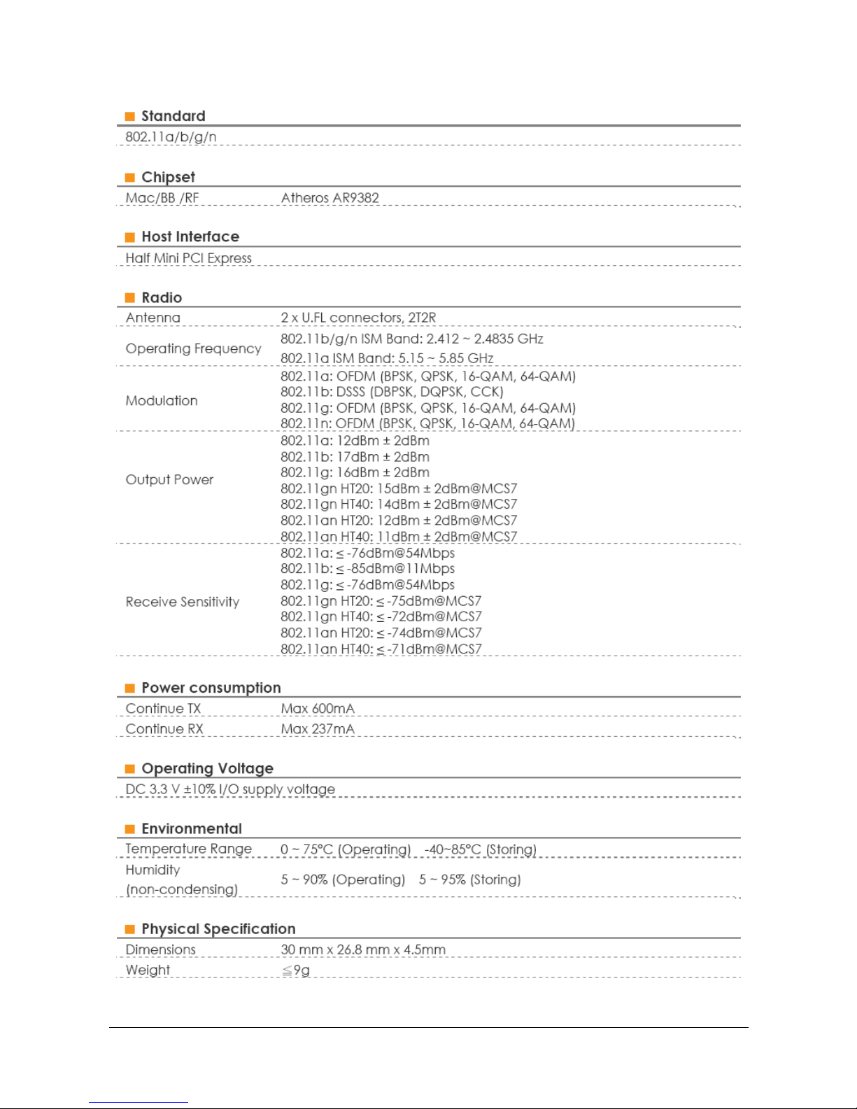
WiFi (optional)
Antenna type: Fakra D code (Green)
Antenna impedance: 50 Ohms
Page 45
DOC 02110-1 ACTIA PCs Page 45 / 52
Module: SparkLan WPEA-121N
Page 46

DOC 02110-1 ACTIA PCs Page 46 / 52
RTC Battery
Battery type: CR2032
Long life: 39000h (without external power supply)
Page 47
DOC 02110-1 ACTIA PCs Page 47 / 52
MAINTENANCE
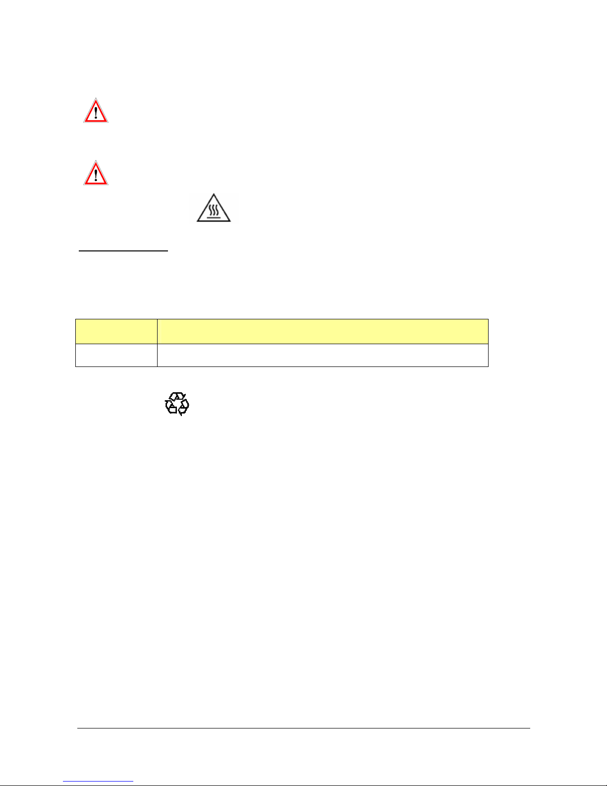
Before any maintenance operation, switch off the power, disconnect the vehicle
battery and then disconnect all IHMI v2 connectors.
After the maintenance operation: connect the connectors to the IHMI v2 and
then reconnect the vehicle battery.
Be careful with the IHMI v2 case, in some conditions it could be hot.
CAUTION: HOT SURFACE
Battery replacement
The IHMI v2 includes a battery. This battery could not be accessed easily. Contact ACTIA PCs SAV for more
details. In case of replacement, use the same battery type, characteristics and polarity, otherwise a battery
explosion can occur.
Location Designation
Internal Lithium Battery CR2032: 3V
Don’t forget to recycle old batteries.
Page 48
DOC 02110-1 ACTIA PCs Page 48 / 52
APPENDICES
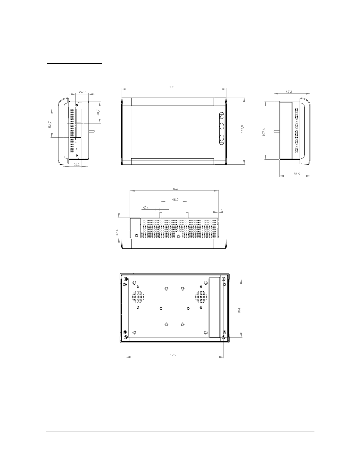
Mechanical drawings
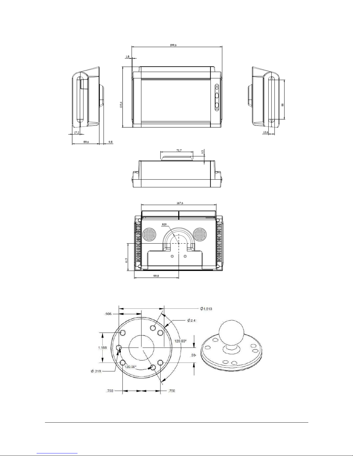
IHMI v2 case
Page 49
DOC 02110-1 ACTIA PCs Page 49 / 52
IHMI v2 with back plastic cover
Round base ball (dashboard fixing)
Page 50
DOC 02110-1 ACTIA PCs Page 50 / 52
Product label
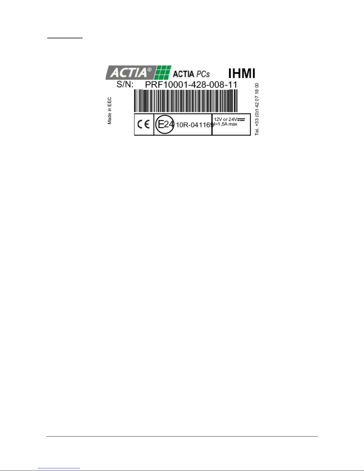
To identify each system, a sticker is placed on the rear panel of the product.
PRFxxxxx-yww-zzz-11
xxxxx = Product code
yww = Year + week (ex: 428 = 2014, week 28)
zzz = serial number
11 = revision
E24 xxR–xxxxxx =E-marking number
Page 51
DOC 02110-1 ACTIA PCs Page 51 / 52
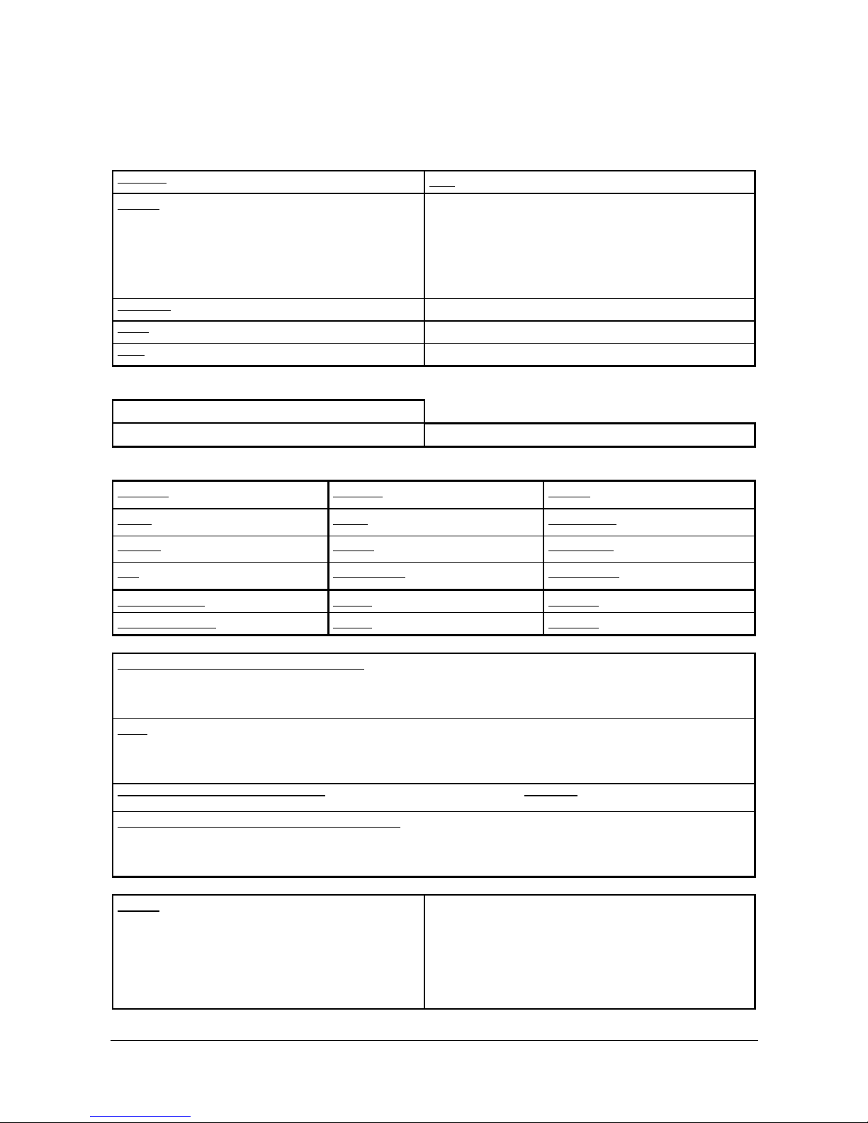
INCIDENT REPORT SHEET
Before returning the product, it is essential to contact the ACTIA PCs After Sales Service to obtain a return number (RMA) to be written
in the box of this document. The information which will be shown on this sheet will be used to determine the cause(s) of the fault or
malfunction, thereby helping to improve the quality of our services. Please complete and return this card.
Company:
Date:
Address:
Return to:
ACTIA PCs
SAV – RMA
14 rue Charles Martigny
94700 Maisons Alfort - France
Telephone:
Tel.: 01.42.07.18.00
Name:
Fax: 01.42.07.85.55
Email
Email: [email protected]
Product reference: IHMI v2
ROM version: Serial No.:
Processor: Hard Disk:
Yes No
Memory:
Speed: Floppy:
Yes No
Display board:
Radiator:
Yes No
CDRom:
Yes No
Other boards:
Fan:
Yes No
CompactFlash:
Yes No
Miscellaneous:
Operating system: Version: Language:
Application software: Version: Language:
Error messages generated by the operating system:
Other:
Have you encountered this problem before? YES / NO Frequency:
Indicate the operations which cause the anomaly to appear:
Solution:
Reserved box
RMA NUMBER
Page 52

DOC 02110-1 ACTIA PCs Page 52 / 52
NOTES
 Loading...