

ACTi ZNR-421, ZNR-220P, ZNR-120P, ZNR-121P User Manual

User’s Manual
ZNR
2020/01/06

www.acti.com
www.acti.com
User’s Manual
Table of Contents
User’s Manual .................................................................... 1
ZNR ..................................................................................... 1
Table of Contents .............................................................. 1
Preface ............................................................................... 5
Safety Information..................................................................................... 5
Regulatory Compliance ............................................................................ 6
LVD/EMC Directive ................................................................................... 6
WEEE Directive–2012/19/EU ................................................................... 6
Part I Local Operations ..................................................... 7
Before You Begin .............................................................. 8
Disk Installation......................................................................................... 8
Ports, Interfaces and LEDs ......................................................................10
Startup .....................................................................................................11
Live View .................................................................................................11
Playback ..................................................................................................11
Access Using a Web Browser .................................................................11
Shutdown .................................................................................................12
Login ........................................................................................................12
Local Operations......................................................................................12
Initial Configuration ........................................................ 16
Preparation ..............................................................................................16
Wizard .....................................................................................................16
Live View .......................................................................... 19
Live View Status ......................................................................................19
Live View Window Icons ................................................. 19
Window Toolbar .......................................................................................20
Screen Toolbar ........................................................................................21
Shortcut Menu ................................ .........................................................22
Sequence Operation ................................................................................23
Zoom .......................................................................................................24
1

www.acti.com
www.acti.com
User’s Manual
Image Configuration ................................................................................24
Preview Configuration ..............................................................................25
Channel Configuration ................................................... 27
Channel Management .............................................................................27
OSD Configuration ...................................................................................31
Image Configuration ................................................................................31
Privacy Mask Configuration .....................................................................35
PTZ Control ...................................................................... 36
PTZ Control Window and PTZ Management Window .............................36
Setting and Calling a Preset ....................................................................37
Setting a Preset Patrol .............................................................................38
Setting a Recorded Patrol ........................................................................39
Setting Auto Guard ..................................................................................39
Recording and Snapshot ................................................ 40
Encoding Settings ....................................................................................40
Draw or Edit a Schedule ..........................................................................43
Scheduled Recording and Snapshot .......................................................44
Motion Detection Recording and Snapshot .............................................45
Alarm Triggered Recording and Snapshot ...............................................47
Manual Recording and Snapshot.............................................................48
Holiday Recording and Snapshot ............................................................49
Other Recording and Snapshot Types .....................................................50
Playback ........................................................................... 51
Instant Playback ......................................................................................51
Playback Toolbar .....................................................................................51
Playback by Camera and Date ................................................................52
Playback in Corridor Mode ......................................................................53
Playback by Tag ......................................................................................53
Playback by Event ...................................................................................54
Playback by Smart Search ......................................................................54
Playback by External File ........................................................................55
Playback by Image ..................................................................................55
Playback by POS .....................................................................................55
File Management .....................................................................................56
Backup ............................................................................. 57
Recording Backup ...................................................................................57
Image Backup ..........................................................................................58
2

www.acti.com
www.acti.com
User’s Manual
Alarm ................................................................................ 59
Alarm Input and Output ............................................................................59
Motion Detection ......................................................................................61
Tampering Detection ...............................................................................62
Video Loss ...............................................................................................62
VCA .........................................................................................................63
Alert .........................................................................................................68
Buzzer .....................................................................................................68
Alarm-Triggered Actions ..........................................................................69
Manual Alarm ..........................................................................................69
VCA Search ...................................................................... 70
Behavior Search ......................................................................................70
Face Search ............................................................................................71
People Counting ......................................................................................72
Network Configuration ................................................... 73
Basic Configuration ..................................................................................73
PPPoE .....................................................................................................74
DDNS ......................................................................................................75
3G/4G ......................................................................................................76
Port ..........................................................................................................76
Port Mapping ........................................................................................... 77
Email ........................................................................................................79
FTP ..........................................................................................................80
Multicast ..................................................................................................81
Disk Configuration .......................................................... 82
Disk Management ....................................................................................82
Array Configuration ..................................................................................83
Disk Group ................................................................ ............................... 85
Space Allocation ......................................................................................85
Advanced Configuration ..........................................................................86
Hard Disk Detection .................................................................................86
System Configuration ..................................................... 88
Basic Configuration ..................................................................................88
Time Configuration ..................................................................................88
Transaction Configuration ........................................................................90
Serial Port Configuration ..........................................................................90
User Configuration ...................................................................................91
3

www.acti.com
www.acti.com
User’s Manual
Security Configuration .............................................................................92
Hot Spare Configuration ..........................................................................94
System Maintenance ....................................................... 95
System Information ..................................................................................95
Network Information .................................................................................97
Log Query ................................................................................................99
Import/Export .........................................................................................100
System Restoration ...............................................................................100
Automatic Maintenance .........................................................................100
System Upgrade ....................................................................................101
Shutdown ....................................................................... 102
Part II Web-Based Operations ...................................... 103
Before You Begin .......................................................... 103
Login .............................................................................. 104
Live View ........................................................................ 105
Playback ......................................................................... 106
Configuration ................................................................. 106
Appendix A Typical Applications ................................ 107
Typical Application 1 ..............................................................................107
Typical Application 2 ..............................................................................107
Appendix B Acronyms .................................................. 108
Appendix C FAQs .......................................................... 109
4

www.acti.com
www.acti.com
User’s Manual
Preface
This manual describes how to use your NVR locally or on the Web interface.
In this manual, the terms IP camera and IPC refer to the same thing: network camera, which
requires a connection to the network. And the IP device mentioned in this manual refers to an IP
camera (also known as network camera) or a Digital Video Server (DVS).
Thank you for purchasing our product. Contact your local dealer if you have any questions or
feedback. No part of this manual may be copied, reproduced, translated, or distributed in any
form or by any means without prior consent in writing from our company. Contents of this manual
are subject to change without prior notice. No statement, information, or recommendation in this
manual shall constitute formal guarantee of any kind, expressed or implied.
Safety Information
Read through the instructions carefully before starting installation and operation.
Installation and maintenance must be performed by qualified personnel.
This device is a class A product and may cause radio interference. Take measures if
necessary.
Disconnect power before installation and cable connection. Wear antistatic gloves
during installation. Use the manufacturer recommended battery. Improper use or
replacement of the battery may cause risk of explosion. Dispose of the used battery
according to local regulations or the battery manufacturer's instructions. Never dispose
of the battery in fire.
The device is intended for indoor use only. Ensure a proper operating environment,
including temperature, humidity, ventilation, power supply, and lightning protection.
The device must always be properly grounded. Keep the device from dust, excessive
vibration, liquid of any kind, and strong electromagnetic radiation. A sudden power
failure may cause device damage or loss of data.
Take necessary measures to ensure data security and protect from network attack and
hacking (when connected to Internet).
5
www.acti.com
www.acti.com
User’s Manual
This product complies with the European Low Voltage Directive 2014/35/EU and
EMC Directive 2014/30/EU.
The product this manual refers to is covered by the Waste Electrical & Electronic
Equipment (WEEE) Directive and must be disposed of in a responsible manner.
Regulatory Compliance
FCC Part 15
This equipment has been tested and found to comply with the limits for digital device, pursuant
to part 15 of the FCC Rules. These limits are designed to provide reasonable protection against
harmful interference when the equipment is operated in a commercial environment. This
equipment generates, uses, and can radiate radio frequency energy and, if not installed and
used in accordance with the instruction manual, may cause harmful interference to radio
communications. Operation of this equipment in a residential area is likely to cause harmful
interference in which case the user will be required to correct the interference at his own
expense.
This product complies with Part 15 of the FCC Rules. Operation is subject to the following two
conditions:
This device may not cause harmful interference.
This device must accept any interference received, including interference that may
cause undesired operation.
LVD/EMC Directive
WEEE Directive–2012/19/EU
6

www.acti.com
www.acti.com
User’s Manual
Part I Local Operations
An NVR supports two types of operations: local operations and web-based remote operations.
With local operations you connect a monitor and a mouse to the NVR and use the mouse to
operate. If your NVR has buttons on the front panel or is delivered with a remote control, you
may also control your NVR by pressing the front panel buttons or using the remote control.
The NVR has an embedded web server and allows web-based operations. To do this, you need
a PC that has a network connection to the NVR and is installed with a web browser. You just
need to navigate to the NVR's IP address and log in to the Web interface like you log in to the
system locally.
This section describes local operations.
7
www.acti.com
www.acti.com
User’s Manual
Before You Begin
Please be aware that the parameters that are grayed out on the system user interface (UI)
cannot be modified. The parameters and values displayed may vary with device model, and the
figures in this manual are for illustration purpose only.
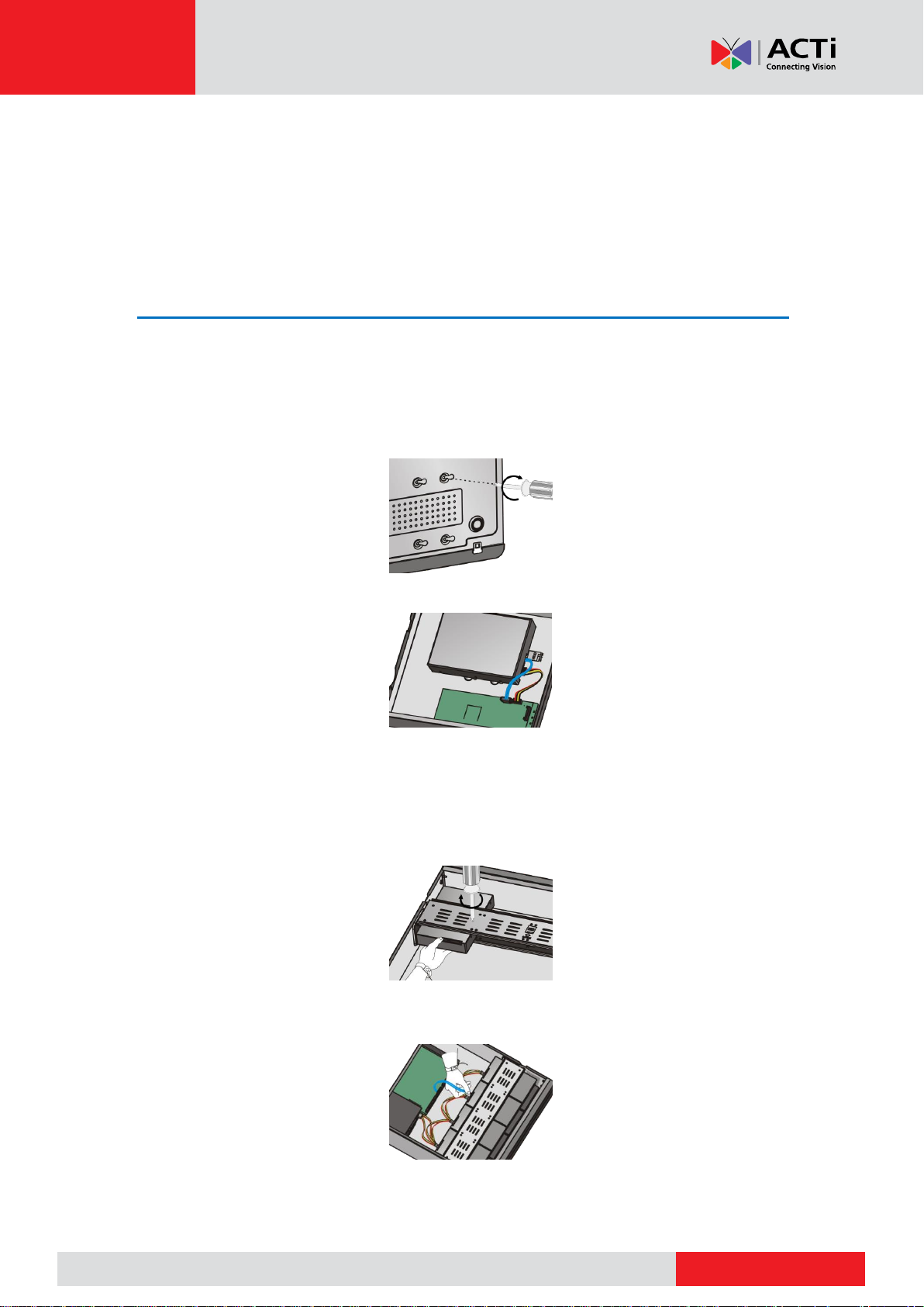
Disk Installation
Choose an option. Use a #1 or #2 screwdriver as needed. All photos are only for illustration.
Option 1 (for 1 or 2 disks)
1. Remove the cover, connect data and power cables to disk(s), and then secure disk(s) with
screws.
2. Connect data and power cables to the motherboard and then install the cover.
Option 2 (for more than 2 disks)
Open the cover and install hard disks on mounting plate(s).
1. Remove the cover and then secure disks to mounting plate(s) with screws.
2. Connect data and power cables to disks. Secure mounting plate(s) to the device, and then
install the cover.
8
www.acti.com
www.acti.com
User’s Manual
用螺钉将硬盘固定在拉手条上,拉
手条注意区分左右
用双手分别按住前面板两侧卡扣,
按方向②拆卸前面板
用螺钉将硬盘固定在拉手条上,拉
手条注意区分左右
用拇指推进硬盘,可听到扣上的声音,
完成该硬盘安装
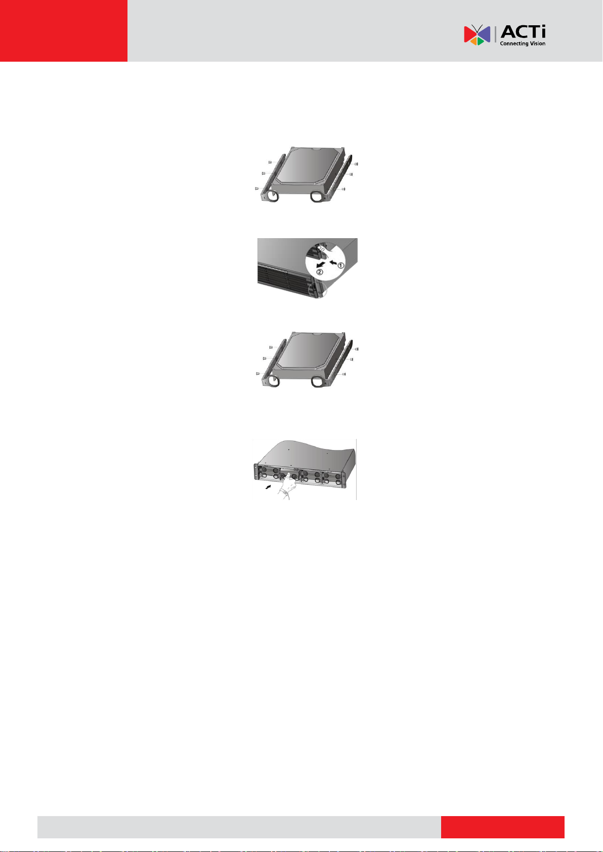
Option 3 (for more than 2 disks)
Open the front panel and install hard disks on mounting brackets.
1. Secure the disk to a pair of mounting brackets (L means left and R means right).
2. Press the latches on both sides (1) and then detach the front panel (2).
3. Align the disk at the slot and then insert the disk gently.
4. Push the disk slowly until it clicks. Repeat the steps to install all disks and then close the
front panel.
9
www.acti.com
www.acti.com
User’s Manual
LED
Description
PWR(Power)
Steady on: Connected to power.
RUN(Operation)
Steady on: Normal.
Blinks: Starting up.
NET(Network)
Steady on: Connected to network.
GUARD(Arming)
Steady on: Arming is enabled.
IR
Steady on: Activated for remote control.
Blinks: Authenticating device code.
ALM(Alarm)
Steady on: Device alarm occurred.
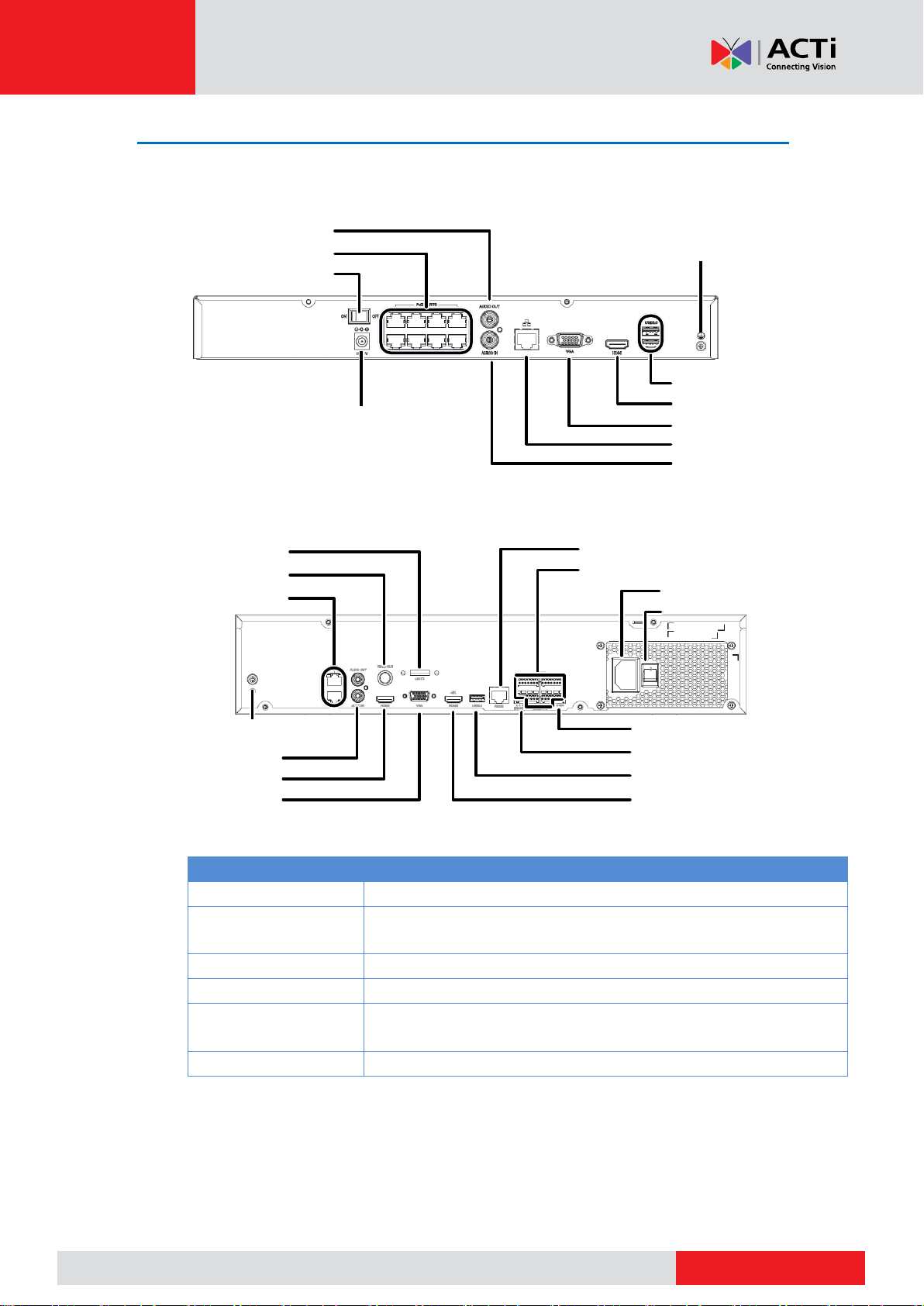
Power on/off
Audio output
DC power
PoE ports
Audio input
Network
VGA output
HDMI output
USB
Grounding
AC power
USB
Alarm input/output
Power on/off
Grounding
Network
HDMI output
VGA output
Audio out/input
RS485
RS232 (for maintenance)
HDMI output
12V DC output
CVBS output
eSATA interface
Ports, Interfaces and LEDs
The ports, interfaces, connectors, power on/off switch and LED indicators may vary with device
model. See the following two examples.
10

www.acti.com
www.acti.com
User’s Manual
LED
Description
HD(Hard disk)
One HD LED only:
Steady on: No disk; or disk is abnormal.
Blinks: Reading or writing data.
One HD LED for each disk:
Steady green: Normal.
Blinks green: Reading or writing data.
Steady red: Abnormal.
Blinks red: Rebuilding array.
Startup
Verify installation and cable connection are correct. Connect to power and then turn on the
power on/off switch (if applicable). Follow the wizard to complete the basic setup after the NVR
starts up.
Live View
Click Menu > Camera > Camera. The discovered cameras are listed. Click to add a camera.
To search a network segment, click Search. If a camera is added but live video is not available,
check network connection and make sure the correct camera username and password are set in
the system. Modify if necessary.
Playback
Right-click a preview window and then choose Playback to view video recorded on the current
day. A 7×24 recording schedule is enabled at delivery and can be edited under Menu > Storage
> Recording.
Access Using a Web Browser
Access the NVR using a Web browser (e.g., Internet Explorer) from a connected computer.
Enter the NVR's IP address in the address bar and then press Enter. Install the plugin as prompted. Close
all Web browsers when the installation starts.
Open the Web browser and log in with the correct username and password.
11

www.acti.com
www.acti.com
User’s Manual
Name
Action
Description
Left button
Click
Select or confirm an item.
Select to edit digits, symbols, upper-case or lower-case
letters in a field.
Double-click
Enter or exit full screen mode in live view.
Drag
Draw or move a rectangle on the screen, for example, a
motion detection area.
Right button
Click
Show the shortcut menu.
Exit zoom.
Exit the current window when Cancel or Exit is
displayed.
Wheel
Scroll up or down
Scroll up or down a list or a window; or zoom in or out
on a playback progress bar.
Shutdown
Use the Shutdown menu instead of by disconnecting power or turning off the power on/off
switch. A sudden power failure may cause device damage and loss of data.
Login
Use the default username admin and password 123456 for your first login.
CAUTION: The default password is intended only for the first login and should be changed
to a strong one containing at least eight characters including uppercase and lowercase letters,
digits and symbols after your first login to ensure security.
1. Right-click anywhere in the window and then choose Menu. The login dialog box is
displayed.
2. Select the username from the drop-down list, enter your password, and then click Login.
Local Operations
You can refer to Initial Configuration and complete a quick configuration.
NOTE: Unless otherwise specified, all operations described in this manual are performed with a
mouse by the right hand. See Error! Reference source not found. for details.
Mouse Operations
12
www.acti.com
www.acti.com
User’s Manual
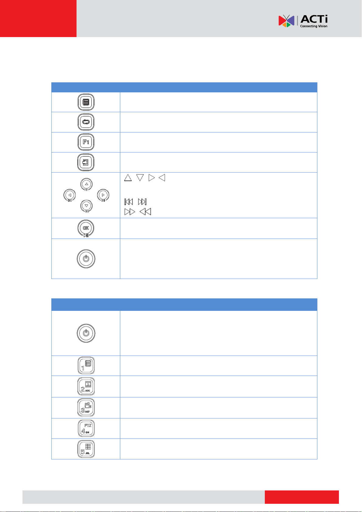
Button
Description
Display the main menu.
Switch to the next tab on the screen or switch the input method.
Auxiliary function button.
Exit the current window.
, , , : Switch windows or menu items; or control rotation
directions of a PTZ camera when the PTZ toolbar is closed. PTZ
stands for pan, tilt, and zoom.
, : Rewind or forward 30 seconds in full screen.
, : Variable-speed forward or rewind in full screen.
Confirm an operation, or start/pause the playback.
Press this button to start up or shut down the NVR.
To shut down, press this button and hold for at least 3 seconds till a
message appears on your monitor. Click Yes.
NOTE: This shutdown operation can be performed only when you
have logged in to the system.
Button
Description
Press this button to start up or shut down the NVR.
To shut down, press this button and hold for at least 3 seconds till a
message appears on your monitor. Click Yes.
NOTE: This shutdown operation can be performed only when you
have logged in to the system.
Enter 1; or display the main menu.
Enter 2, A, B, or C; or start instant playback.
Enter 3, D, E, or F; or start manual recording.
Enter 4, G, H, or I; or enter the PTZ control interface.
Enter 5, J, K, or L; or switch the screen layout in live view or playback
mode.
Front Panel Buttons
The front panel buttons may vary with NVR model.
Front Panel Buttons 1
Front Panel Buttons 2
13
www.acti.com
www.acti.com
User’s Manual
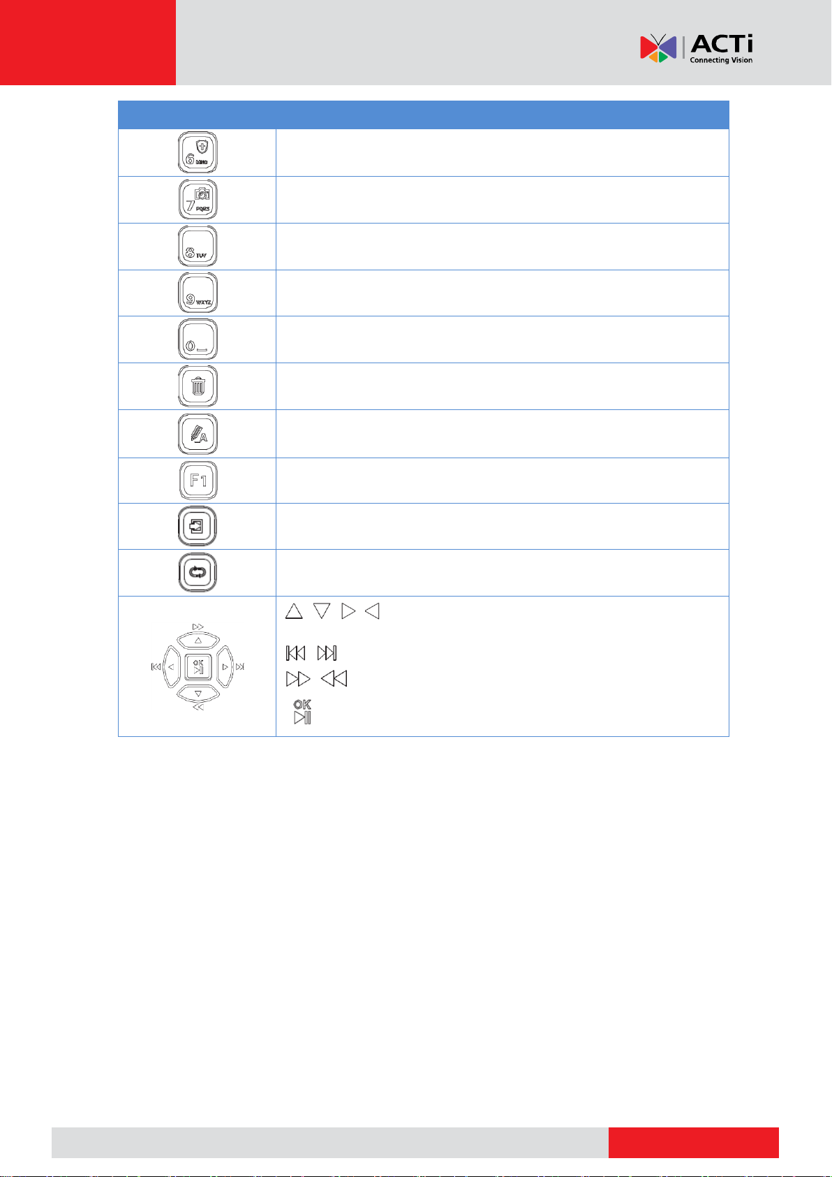
Button
Description
Enter 6, M, N, or O; or enable or disable arming.
Enter 7, P, Q, R, or S; or take a snapshot.
Enter 8, T, U, or V.
Enter 9, W, X, Y, or Z.
Enter 0 or a space.
Delete
Switch the input method.
Auxiliary function button.
Exit the current window.
Switch to the next tab.
, , , : Switch windows or menu items; or control rotation
directions of a PTZ camera when the PTZ toolbar is closed
, : Rewind or forward 30 seconds in full screen.
, : Variable-speed forward or rewind in full screen.
: Confirm an operation; or start or pause playback.
14

www.acti.com
www.acti.com
User’s Manual
Button
Function
Power
Press this button to start up or shut down the NVR.
To shut down, press this button and hold for at least 3 seconds till a
message appears on your monitor. Click Yes.
NOTE: This shutdown operation can be performed only when you
have logged in to the system.
DEV
This button is for reserved functions.
Toolbar
In live view mode, press this button to show the toolbar for the
currently selected window.
In playback mode, press this button to display windows
according to the configured screen layout.
Menu
Press this button to display the main menu.
Iris+/Iris-
Adjust the iris, focus and zoom of the PTZ camera in PTZ control
mode.
Focus+/Focus-
Zoom+/Zoom-
UP, DOWN, LEFT,
RIGHT, ENTER
Press UP, DOWN, LEFT and RIGHT to navigate between menu
items or shift focus.
In PTZ control mode, press UP, DOWN, LEFT, and RIGHT
buttons to select the corresponding buttons on the screen, and
then press ENTER to activate the selection.
In live view mode, press UP to start sequence in full screen.
Pressing UP again starts sequence with three windows on the
screen. Press DOWN to open the playback window.
Press ENTER to confirm an operation or to display a selected
drop-down list. In playback mode, press ENTER to play or pause
in full screen mode.
UP and DOWN: Variable speed forward or rewind in full screen.
LEFT and RIGHT: Rewind or forward 30 seconds in full screen.
Fn
Press to navigate to the next window when multiple windows are
displayed.
Esc
Exit.
Alphanumeric buttons
Switch to the corresponding channel in live view mode.
Input numbers and characters in edit mode.
Shift
Switch menu items.
Del
Remove characters or spaces on the left of the cursor.
Remote Control
Functions of the Buttons on the Remote Control
15
www.acti.com
www.acti.com
User’s Manual
Initial Configuration
Preparation
Make sure that at least one monitor is correctly connected to the VGA or HDMI
interface on the rear panel of the NVR.
Verify that the hard disk(s) are correctly installed. For detailed steps to install a hard
disk, please refer to the quick guide shipped with your NVR.
Wizard
The wizard can guide you to complete the most basic setup. The wizard may vary with device
model and other factors. The following shows an example.
1. Enable or disable the wizard as needed and then click Next.
NOTE:
You may change the setting under System > Basic.
If a QR code is displayed, you may scan the code to download an app and use the
app to control your NVR.
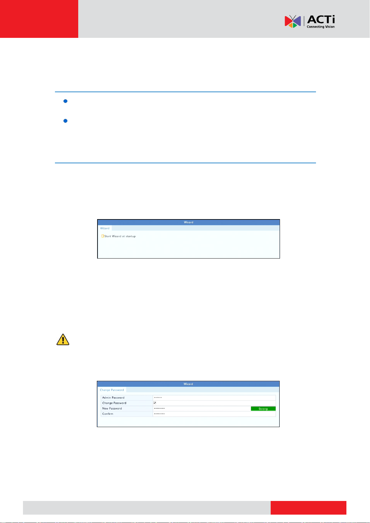
2. Enter the default admin password 123456 and then click Next.
CAUTION: The default password is intended only for the first login and should be changed
to a strong one containing at least eight characters including uppercase and lowercase letters,
digits and symbols after your first login to ensure account security.
NOTE: For RAID models, a window appears following this step for RAID configuration.
16
www.acti.com
www.acti.com
User’s Manual
3. Complete time information and then click Next.
4. Set the IP address, subnet mask, and default gateway. Use the default settings for other
parameters unless modification is necessary. Review the settings and then click Next.
NOTE:
For some NVR models, Enable DHCP is selected by default.
If your NVR has more than one Network Interface Card (NIC), you may configure the
NICs and choose one for default route.
An internal IPv4 address can be configured if your NVR has PoE ports or switching
ports.
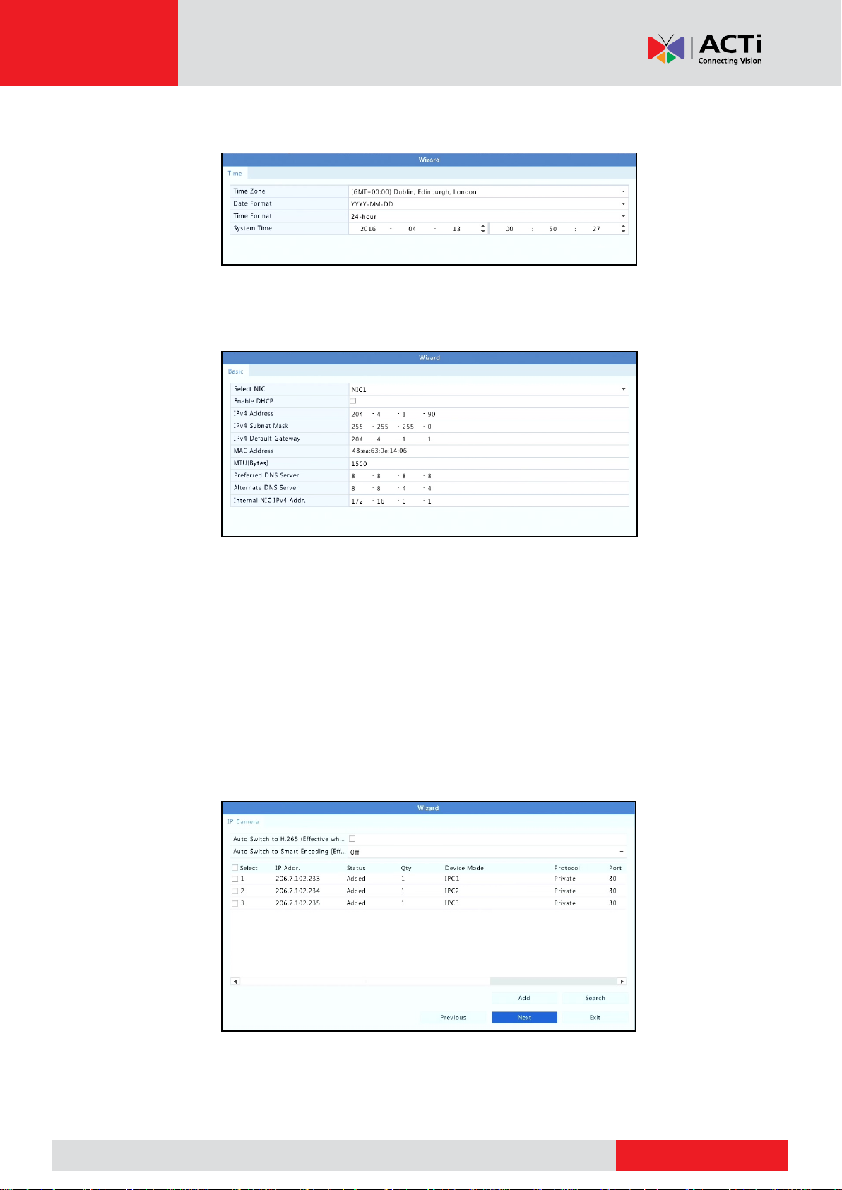
5. Click Search. The detected IP devices are listed. Select the device(s) to add and then click
Add.
6. Click Next.
17
www.acti.com
www.acti.com
User’s Manual
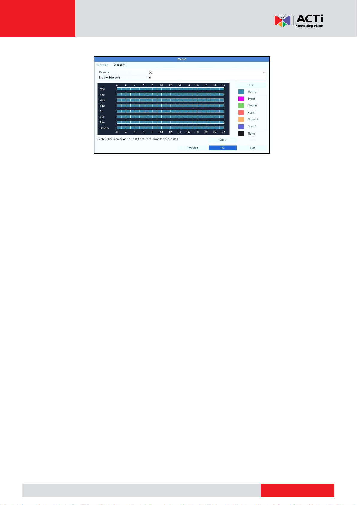
7. Set a recording/snapshot schedule and then click OK.
NOTE: You may also edit wizard settings by clicking Wizard under System > Basic.
18
www.acti.com
www.acti.com
User’s Manual
Icon
Description
Tampering alarm
Motion detection alarm
Recording
Two-way audio
Turn on audio
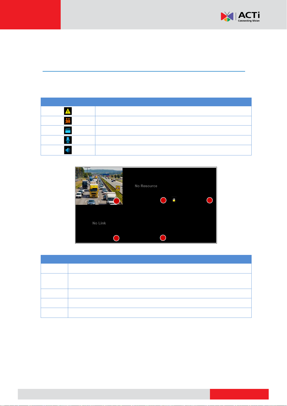
No.
Description
1
The IP device is online, and live video is displayed.
2
The IP device is online, but the NVR has insufficient capacity to decode streams
from the IP device.
3
No permission to view live video from the IP device.
4
The IP device is offline.
5
No IP device is linked to the window.
1
2
4
3
5
Live View
Live View Status
The following icons are used to indicate alarms, recording status, and audio status in a live view
window.
Live View Window Icons
Normally, live video is displayed, but other situations are also possible.
19
www.acti.com
www.acti.com
Window Toolbar
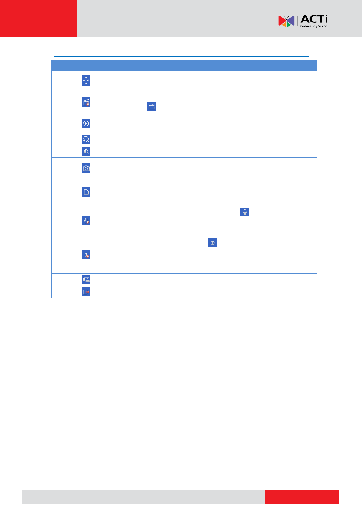
Icon
Description
Available for PTZ cameras only. Click to display the PTZ control
window.
Record live video in the window to the hard disk.
Clicking stops recording.
Click to play video recorded during the past 5 minutes and 30
seconds.
Zoom in on an area of interest.
Click to edit image settings.
Click to take a snapshot. The window borders will flash white.
You may view and back up snapshots under Backup > Image.
Rest your mouse pointer on the icon to view live video information. Or
click it to view the channel number, camera name, IP address,
connection status and recording status.
Start two-way audio with the camera. Click to stop. The sound
volume is adjustable.
NOTE: Correct audio input and output connections are required.
Click to turn on audio. Clicking turns off audio. The sound volume
is adjustable.
NOTE: When you turn on audio in the current window, audio of the
previous window is turned off.
Click to link the window to another IP device.
Exit
User’s Manual
20
www.acti.com
www.acti.com
Screen Toolbar
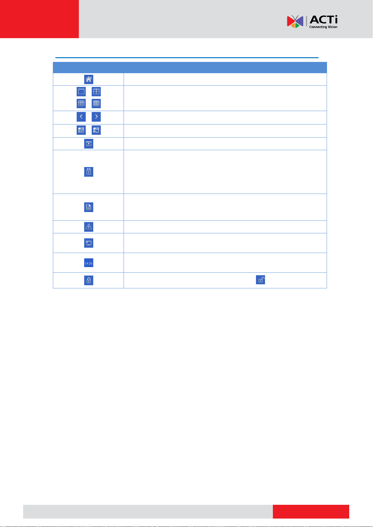
Icon
Description
Click to access the main menu.
/
/
Select the screen layout.
/
Previous or next screen.
/
Start or stop sequence.
Playback.
Click to open the USB Device window and perform USB related
operations. The window offers quick access to multiple windows, and it
pops up automatically if a USB storage device is plugged in when the
NVR is restarting or when the preview window is displayed.
This button is effective only when a USB storage device is plugged in.
Rest the mouse pointer on this icon to view encoding information
including frame rate, bit rate, and resolution; or click to view camera
status.
Click to view device alarm status and camera status.
Rest the mouse pointer on it to view NIC card information. Or click this
icon to edit basic network settings.
Rest the mouse pointer on it to view the date. Or click this icon to edit
time settings.
Click to automatically hide the toolbar, or click to lock.
User’s Manual
21
www.acti.com
www.acti.com
User’s Manual
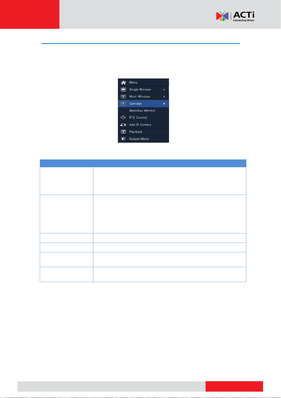
Menu
Description
Menu
Access the main menu.
Most of operations described in this manual are performed start from
the main menu; for example, click Camera > Camera (with Menu >
omitted).
Corridor
Choose a corridor mode. Corridor mode can also be set in the Default
Layout drop-down list under System > Preview.
To display images in corridor mode, the camera must be installed
correctly (rotated 90° clockwise or counterclockwise), and then use the
Image Rotation parameter under Camera > Image to rotate images
accordingly.
Main/Aux Monitor
Switch live video from different video output.
PTZ Control
Display the PTZ control window for the first PTZ camera in live view.
Playback
Play the current day's recording for the camera linked to the current
window.
Output Mode
Choose a video output mode, including standard, soft, bright, and
vivid.
Shortcut Menu
A shortcut menu as shown below appears when you right-click in a window. Some menu items
are described in Shortcut Menu Description.
Shortcut Menu
Shortcut Menu Description
22

www.acti.com
www.acti.com
User’s Manual
Sequence Operation
The sequence operation requires you to configure the screen layout, windows, linked cameras,
and the sequence interval.
This example describes how to configure sequence for five cameras based on a 4-window
screen layout.
1. Click 4 Windows on the screen toolbar.
NOTE: The number of windows that can be displayed may vary with NVR model.
2. Click Start Sequence on the screen toolbar. Sequence starts by displaying four windows on
the first screen and then the fifth on the second screen at the set interval.
NOTE:
The default sequence interval is eight seconds and can be set under System >
Preview.
You may drag video to the desired window on the screen.
23
www.acti.com
www.acti.com
User’s Manual
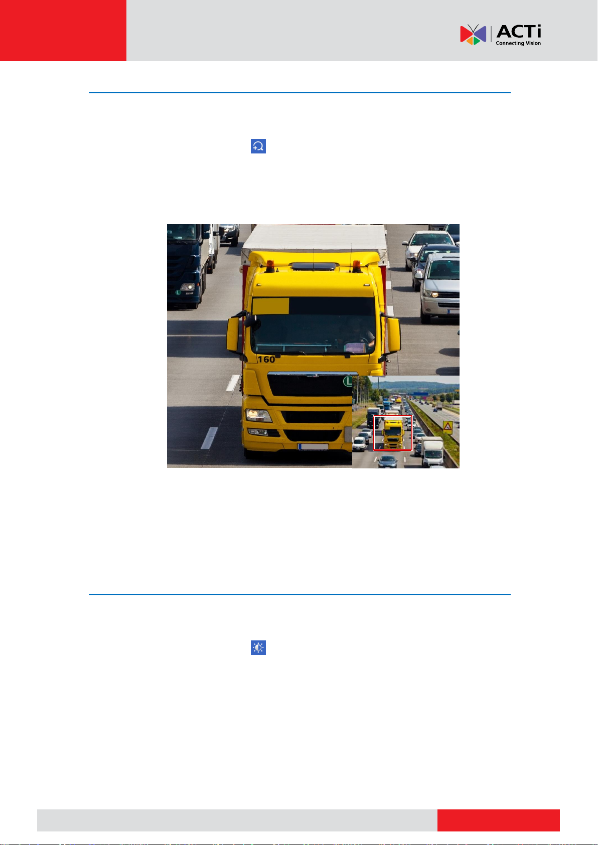
Zoom
Zoom in on an area of images in a window for details.
1. Click the window and then click on the window toolbar.
2. In the small window in the lower right corner, click and drag your mouse to specify the area
to zoom in on. The image in the main window zooms in. The following shows an example.
NOTE: The system adjusts the area automatically according to the window size and its aspect
ratio. Also, the system has specified a minimum size to ensure zoom effects.
Image Configuration
Adjust image settings to get optimal images from a camera.
1. Click the window and then click on the window toolbar.
2. Select a mode from the drop-down list according to the surveillance scenario, and then
adjust contrast, hue, saturation and brightness as needed. The settings available may vary
with device model.
3. Click OK to save the settings and exit.
24

www.acti.com
www.acti.com
User’s Manual
Preview Configuration
Normally, live view (video) is available after you complete the basic setup by following the
wizard. You can click System > Preview and edit preview setting as needed, including video
output, image resolution, default layout, and sequence interval. The video output and the
number of windows supported may vary with NVR model.
NOTE:
Pressing and holding the scroll wheel for at least 3 seconds will restore the default
resolution.
For remote live view, it is recommended to limit up to 4 channels at 1080p only to avoid
screen flickering. Nevertheless, if flickering screen occurs, it happens only on live view,
the recorded video is not affected.
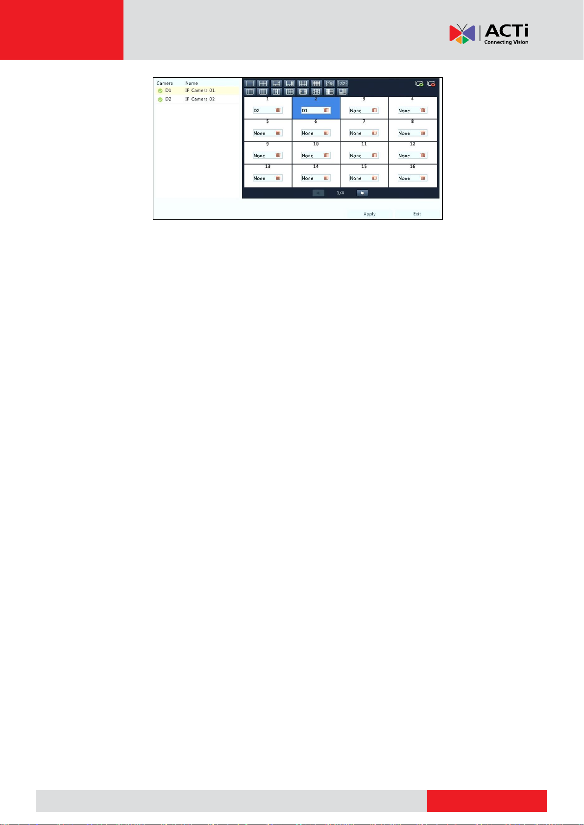
Preview Configuration
Each preview window (window for short) links to a camera. By default, window 1 links to camera
D1, window 2 links to camera D2, and so on. You may want to change the link to display live
video from a camera in another specified window. The following example describes how to link
window 1 to camera D2 and link window 2 to camera D1.
1. Click window 1 on the right, and then click D2 under Camera on the left. Now D2 appears in
window 1, and None appears in window 2. Meanwhile, is cleared for camera D1, meaning
D1 is not linked to any window.
2. Click window 2 on the right, and then click D1 under Camera on the left. Now D1 appears in
window 2. Click Apply to save the settings.
25
www.acti.com
www.acti.com
User’s Manual
Advanced Configuration
Click the Advanced tab and then select Sub Stream First so the NVR uses the sub stream to
establish live video from multiple cameras simultaneously. This function is disabled by default.
26
www.acti.com
www.acti.com
User’s Manual
Channel Configuration
Channel Management
This chapter describes how to add and manage IP devices in your NVR. The IP devices
mentioned in this manual mainly refer to IP camera (or network camera); sometimes they can
also be Digital Video Server (DVS). Before you start, make sure the IP devices are connected to
your NVR via network.
CAUTION: An IP device should be connected to one NVR only. An IP device managed by
multiple NVRs may cause unwanted issues.
Adding an IP Device
This section provides multiple options to add an IP device. Some options are only applicable to
certain NVR models. Choose one as appropriate.
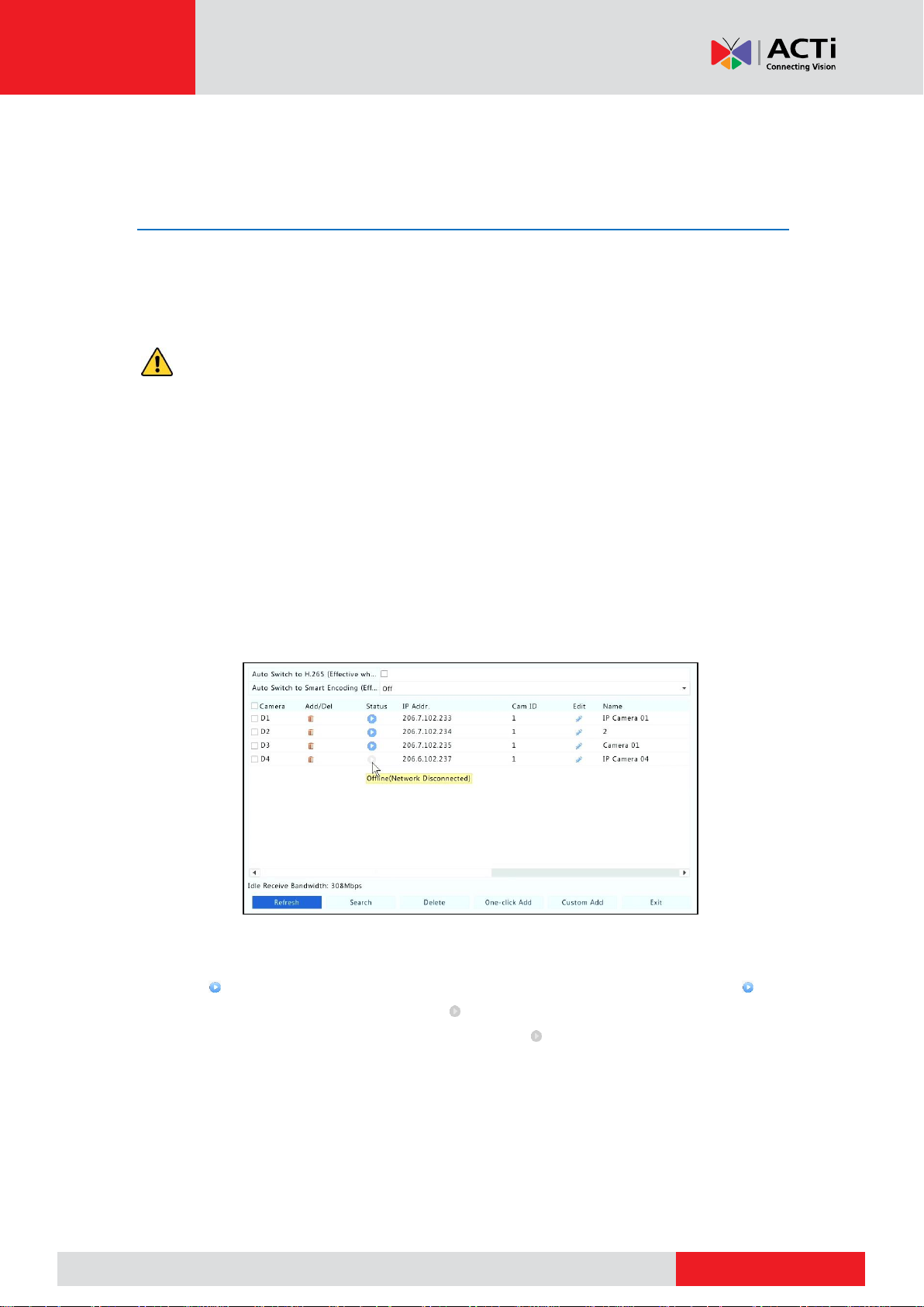
Option 1
1. Click Camera > Camera > Camera. The system automatically searches for IP devices and
lists the discovered.
NOTE:
under Status means an IP device is added successfully, and you may click to
view live video from the IP device. means the IP device is offline, and you may view
the cause by resting the mouse pointer on the .
The idle bandwidth is displayed to indicate current bandwidth available for receiving
streams. For more details, see Network Statistics.
2. (Optional) To search a specified network segment, click Search and then set the address
range.
27

www.acti.com
www.acti.com
User’s Manual
3. Click for the IP device to add. Or, you may also
4. Click One-click Add to add all the discovered IP devices allowed (depending on channels
supported by the NVR).
5. Click Custom Add. In the window displayed, enter the IP address and complete other
settings, and then click Add. You may also click Search and add discovered cameras in the
list.
NOTE: For a Digital Video Server (DVS), a window appears when you click Add, and you need
to select channels to add the connected cameras.
Option 2
This option is not applicable to NVRs with PoE ports or switching ports.
1. Click in a window.
2. Select the desired IP device and then click Add.
Option 3
This option is only applicable to NVRs with PoE ports or switching ports. Connect an IP camera
to a PoE port or a switching port with a network cable. The connected camera will be added to
the NVR automatically. Check status under Camera > Camera > Camera. means live video
from the camera is available. Click to view live video.
If the camera is connected via a network switch, click under Edit. In the window displayed,
set Add Mode to Manual and then complete the settings correctly.
NOTE: appears under Status if the power output from a PoE port is below or above the rated
power of the connected camera.
28

www.acti.com
www.acti.com
User’s Manual
Option 4
Use this option only when the IP device to add supports the standard RTSP, and all you need
from the IP device are just view live and playback. IP devices added in this way cannot be
configured from the NVR.
1. Click Camera > Camera.
2. Click Custom Add.
3. Click to select a camera in the list, select Custom from the Protocol drop-down list, and
then click the Protocol button.
4. In the Protocol window, name the protocol, enter the RTSP port number, select a
transmission protocol, input the resource paths, and then click Apply.
NOTE: Contact the camera manufacturer for resource paths.
5. Edit settings in the Add/Modify window as needed, including the IP address, username and
password, and then click Add. Check status in the camera list.
29
 Loading...