

Page 1

VMGB-370
User’s Manual
2020/07/20
Page 2

www.acti.com
VMGB-370 User’s Manual
Table of Contents
Recommended PC Specifications 8
Preparation 9
Connect the Equipment ............................................................................. 9
Configure the IP Addresses ....................................................................... 9
Using DHCP Server to Assign IP Addresses ........................................... 9
Use the Default IP Address of a Camera .............................................. 10
Manually Adjust the IP Address of the PC .............................................. 11
Manually Adjust the IP Addresses of Multiple Cameras ......................... 11
Access the Camera ................................................................................... 13
Using IPv6 to Access the Camera ............................................................ 14
Temperature Measurement 15
Notice ......................................................................................................... 15
Automatic Thermography ........................................................................ 15
Set Thermography Parameters ............................................................. 15
Set Normal Mode .................................................................................. 16
Set Expert Mode ................................................................................... 17
Set Thermography Rule ........................................................................ 18
Point Thermography .............................................................................. 19
Line Thermography ............................................................................... 19
Area Thermography .............................................................................. 19
Set Shielded Region ............................................................................. 19
Manual Thermography ............................................................................. 20
Measure Body Temperature ..................................................................... 21
Body Thermography 22
Set Body Thermography Parameters ...................................................... 22
Set Body Thermography .......................................................................... 23
2
Page 3

www.acti.com
VMGB-370 User’s Manual
Measured Body Temperature in Thermal Channel ................................ 23
Measure Face Temperature in Optical Channel .................................... 24
Set Face Capture ...................................................................................... 25
Overlay and Capture ............................................................................. 25
Set Shield Region ................................................................................. 25
Advanced Configuration ................................ ................................ ........ 25
Event and Alarm 26
Set Motion Detection ................................................................................ 26
Normal Mode ........................................................................................ 27
Expert Mode .......................................................................................... 27
Set Video Tampering Alarm ..................................................................... 28
Set Alarm Input ......................................................................................... 29
Set Exception Alarm ................................................................................. 30
Detect Audio Exception ............................................................................ 30
Arming Schedule and Alarm Linkage 32
Set Arming Schedule ................................................................................ 32
Linkage Method Settings ......................................................................... 32
Trigger Alarm Output ............................................................................. 32
Manual Alarm ........................................................................................... 33
Automatic Alarm ....................................................................................... 33
FTP/NAS/Memory Card Uploading ....................................................... 33
Send Email ............................................................................................ 34
Set Email ................................................................................................. 34
Notify Surveillance Center ..................................................................... 34
Trigger Recording ................................................................ ................. 35
Set Audible Alarm Output ...................................................................... 35
Set Flashing Alarm Light Output ........................................................... 35
Live View 36
Live View Parameters ............................................................................... 36
Window Division .................................................................................... 36
Live View Stream Type ......................................................................... 36
Enable and Disable Live View ............................................................... 36
3
Page 4

www.acti.com
VMGB-370 User’s Manual
Start Digital Zoom ................................................................ ................. 36
View Previous/Next Page ...................................................................... 36
Full Screen ............................................................................................ 36
Light ...................................................................................................... 37
Wiper..................................................................................................... 37
Lens Initialization .................................................................................. 37
Auxiliary Focus ...................................................................................... 37
Quick Set Live View .............................................................................. 37
Lens Parameters Adjustment ................................................................ 37
Zoom ....................................................................................................... 37
Focus ....................................................................................................... 37
PTZ Speed ............................................................................................... 38
Iris ............................................................................................................ 38
Set Transmission Parameters.................................................................. 38
Video and Audio 40
Video Settings ........................................................................................... 40
Stream Type .......................................................................................... 40
Video Type ............................................................................................ 40
Resolution ............................................................................................. 40
Bitrate Type and Max. Bitrate ................................................................ 41
Video Quality ......................................................................................... 41
Frame Rate ........................................................................................... 41
Video Encoding ..................................................................................... 41
H.264 ....................................................................................................... 41
H.265 ....................................................................................................... 41
MJPEG .................................................................................................... 41
Profile ...................................................................................................... 42
I-Frame Interval ........................................................................................ 42
SVC ......................................................................................................... 42
Smoothing ............................................................................................. 42
Display VCA Info ................................................................................... 42
Audio Settings ....................................................................................... 43
Audio Encoding ................................ ........................................................ 43
Audio Input ............................................................................................... 43
Environmental Noise Filter ....................................................................... 43
Two-way Audio ...................................................................................... 43
Set ROI ................................................................................................. 44
Display Settings ........................................................................................ 45
Image Adjustment ................................ ................................ ................. 45
Image Adjustment (Thermal Channel) .................................................. 45
Background Correction ............................................................................ 45
4
Page 5

www.acti.com
VMGB-370 User’s Manual
Manual Correction .................................................................................... 45
Thermal AGC Mode ................................................................................. 45
Exposure Settings ................................................................................. 46
Day/Night Switch ................................................................................... 46
Set Supplement Light ............................................................................ 46
BLC ....................................................................................................... 47
WDR ..................................................................................................... 47
White Balance ....................................................................................... 47
DNR ...................................................................................................... 47
Defog .................................................................................................... 47
Set Palette ............................................................................................ 47
Set Target Color .................................................................................... 48
DDE ...................................................................................................... 49
Brightness Sudden Change .................................................................. 49
Enhance Regional Image ...................................................................... 49
Mirror..................................................................................................... 49
Video Standard ..................................................................................... 49
Digital Zoom .......................................................................................... 50
Scene Mode .......................................................................................... 50
OSD ............................................................................................................ 50
Displayed Information .............................................................................. 50
Text Overlay ............................................................................................. 50
OSD Parameters ...................................................................................... 50
Set Privacy Mask ...................................................................................... 50
Overlay Picture ......................................................................................... 51
Set Manual DPC (Defective Pixel Correction) ......................................... 51
Set Picture in Picture ................................................................................ 51
Video Recording and Picture Capture 52
Storage Settings ....................................................................................... 52
Set Memory Card .................................................................................. 52
Set NAS ................................................................................................ 52
Set FTP ................................................................................................. 53
Set Cloud Storage ................................................................................. 53
Video Recording ....................................................................................... 54
Record Automatically ............................................................................ 54
Record Manually ................................................................................... 55
Playback and Download Video ............................................................. 55
Capture Configuration .............................................................................. 56
Capture Automatically ........................................................................... 56
5
Page 6

www.acti.com
VMGB-370 User’s Manual
Capture Manually .................................................................................. 56
View and Download Picture .................................................................. 57
Network Settings 58
TCP/IP ........................................................................................................ 58
Multicast Discovery ............................................................................... 59
Port ............................................................................................................ 59
Port Mapping ............................................................................................. 60
Set Auto Port Mapping .......................................................................... 60
Set Manual Port Mapping ...................................................................... 60
Multicast .................................................................................................... 61
SNMP ......................................................................................................... 61
Access to Device via Domain Name ....................................................... 61
Access to Device via PPPoE Dial Up Connection .................................. 62
Set ONVIF .................................................................................................. 63
Set HTTP Listening ................................................................................... 63
System and Security 64
View Device Information .......................................................................... 64
Search and Manage Log .......................................................................... 64
Import and Export Configuration File ..................................................... 64
Export Diagnose Information................................................................... 65
Reboot ....................................................................................................... 65
Restore and Default .................................................................................. 65
Upgrade ..................................................................................................... 65
View Open Source Software License ...................................................... 66
Time and Date ........................................................................................... 66
Synchronize Time Manually .................................................................. 66
Set NTP Server ..................................................................................... 66
Set DST ................................................................................................ 66
Set RS-232 ................................................................................................. 67
Set RS-485 ................................................................................................. 67
Set Same Unit ............................................................................................ 67
6
Page 7

www.acti.com
VMGB-370 User’s Manual
Security ..................................................................................................... 68
Authentication ....................................................................................... 68
Security Audit Log ................................................................................. 69
Search Security Audit Logs ................................................................ ...... 69
Set IP Address Filter ............................................................................. 69
Set SSH ................................................................................................ 70
Set HTTPS ............................................................................................ 70
Create and Install Self-signed Certificate ................................................. 70
Install Authorized Certificate ..................................................................... 70
Set QoS ................................................................................................ 71
Set IEEE 802.1X ................................................................................... 71
User and Account ..................................................................................... 72
Set User Account and Permission ......................................................... 72
Appendix 73
Common Material Emissivity Reference ................................................. 73
7
Page 8

www.acti.com
VMGB-370 User’s Manual
CPU
Core 2 Duo 2.13 GHz or above
Memory
1 GB or higher
Operating System
Windows XP SP1 and above
Windows 7
Windows 8, 8.1
Windows 10
Browser for Accessing
Firmware
Internet Explorer 8 and above
Apple Safari 5.0.2 and above
Mozilla Firefox 5.0 and above
Google Chrome 18 and above
Video Resolution
1024x768 or higher
Recommended PC Specifications
In order to configure or test the cameras, a PC with following basic specifications is needed:
8
Page 9

www.acti.com
VMGB-370 User’s Manual
Preparation
Connect the Equipment
To be able to connect to the camera firmware from your PC, both the camera and the PC have to
be connected to each other via Ethernet cable. At the same time, the camera has to have its own
power supply. In case of PoE cameras, you can use a PoE Injector or a PoE Switch between the
camera and the PC. The cameras that have the DC power connectors may be powered on by
using a power adaptor.
The Ethernet port LED or Power LED of the camera will indicate that the power supply for the
camera works normally.
Configure the IP Addresses
In order to be able to communicate with the camera from your PC, both the camera and the PC
have to be within the same network segment. In most cases, it means that they both should have
very similar IP addresses, where only the last number of the IP address is different from each
other. There are 2 different approaches to IP Address management in Local Area Networks – by
DHCP Server or Manually.
Using DHCP Server to Assign IP Addresses
If you have connected the computer and the camera into the network that has a DHCP server
running, then you do not need to configure the IP addresses at all – both the camera and the PC
would request a unique IP address from DHCP server automatically. In such case, the camera
will immediately be ready for the access from the PC. The user, however, might not know the IP
address of the camera yet. It is necessary to know the IP address of the camera in other to be
able to access it by using a Web browser.
9
Page 10
www.acti.com
VMGB-370 User’s Manual
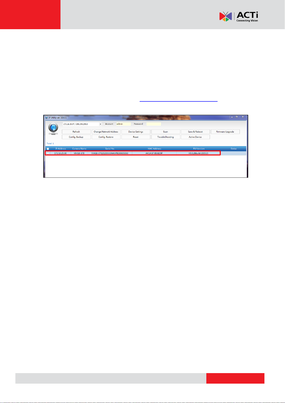
If you work with our cameras regularly, then there is even a better way to discover the
cameras in the network – by using IP Utility. The IP Utility is a light software tool that can not
only discover the cameras, but also list lots of valuable information, such as IP and MAC
addresses, serial numbers, firmware versions, etc, and allows quick configuration of multiple
devices at the same time. Firmware upgrade can also be done through the IP Utility (see IP utility
documentation for more details).
Search and downloand IP Utility for free from http://www.acti.com/DownloadCenter.
With just one click, you can launch the IP Utility and there will be an instant report as follows:
You can quickly notice the camera model in the list. Double-click on the IP address to
automatically launch the default browser of the PC with the IP address of the target camera filled
in the address bar of the browser already.
Use the Default IP Address of a Camera
If there is no DHCP server in the given network, the user may have to assign the IP addresses to
both PC and camera manually to make sure they are in the same network segment.
When the camera is plugged into network and it does not detect any DHCP services, it will
automatically assign itself a default IP:
192.168.0.100
Whereas the default port number would be 80. In order to access that camera, the IP address of
the PC has to be configured to match the network segment of the camera.
10
Page 11
www.acti.com
VMGB-370 User’s Manual
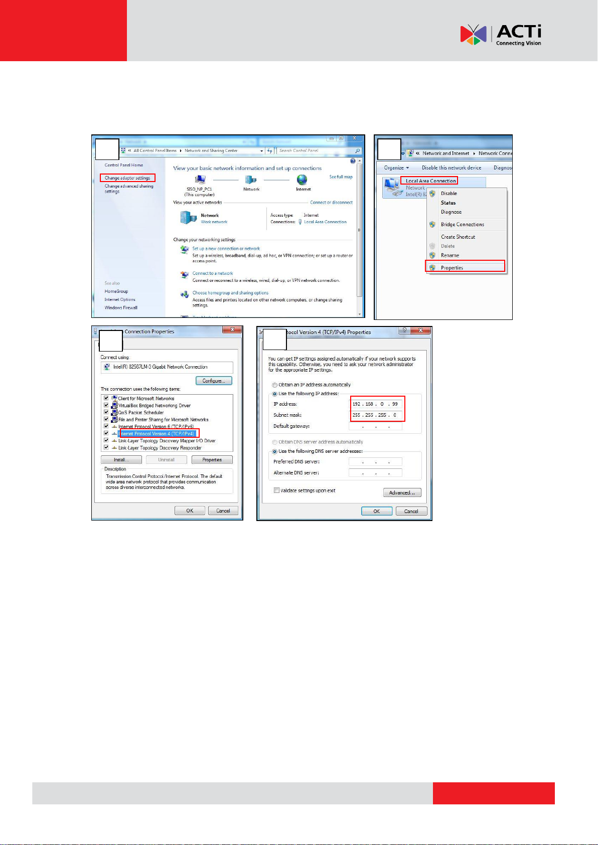
1
2 3 4
Manually Adjust the IP Address of the PC
In the following example, based on Windows 7, we will configure the IP address to 192.168.0.99
and set Subnet Mask to 255.255.255.0 by using the steps below:
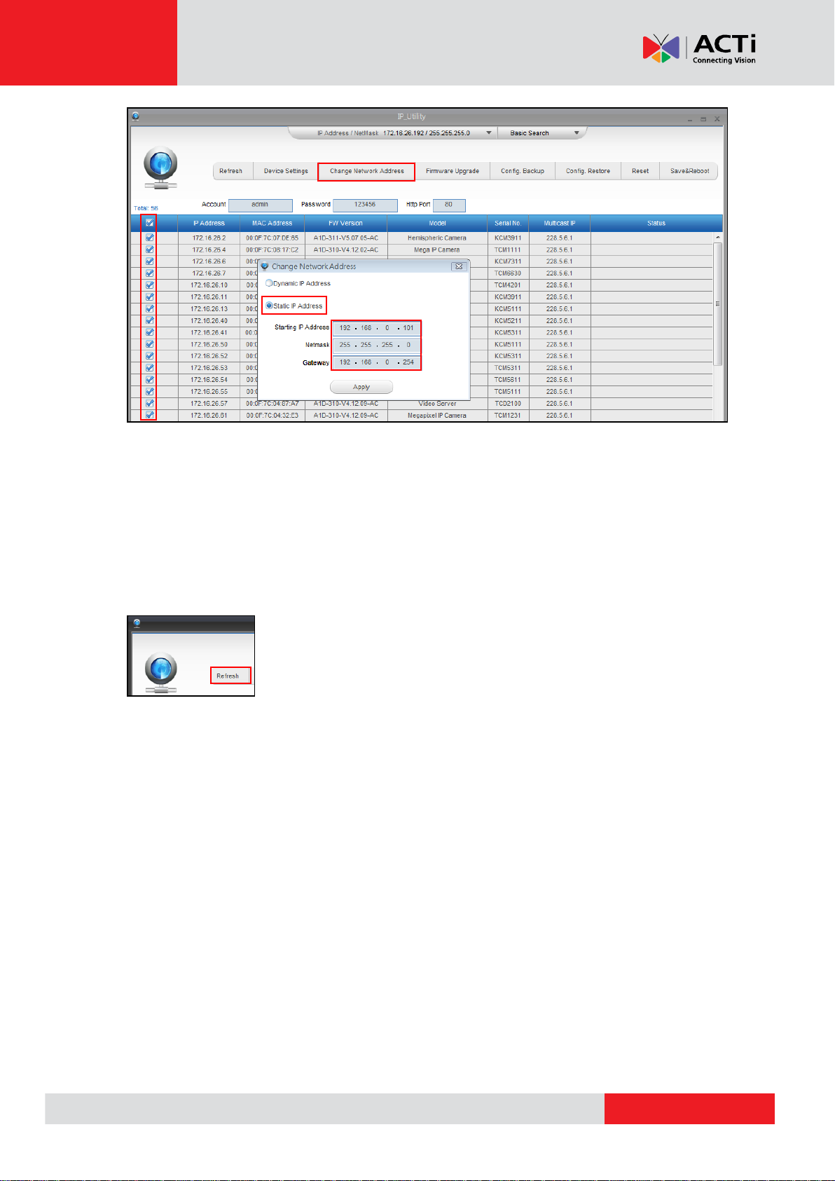
Manually Adjust the IP Addresses of Multiple Cameras
If there are more than 1 camera to be used in the same local area network and there is no DHCP
server to assign unique IP addresses to each of them, all of the cameras would then have the
initial IP address of 192.168.0.100, which is not a proper situation for network devices – all the IP
addresses have to be different from each other. The easiest way to assign cameras the IP
addresses is by using IP Utility:
11
Page 12
www.acti.com
VMGB-370 User’s Manual
With the procedure shown above, all the cameras will have unique IP addresses, starting from
192.168.0.101. In case there are 20 cameras selected, the last one of the cameras would have
the IP 192.168.0.120.
Later, by pressing the “Refresh” button of the IP Utility, you will be able to see the list of cameras
with their new IP addresses.
Please note that it is also possible to change the IP addresses manually by using the Web
browser. In such case, please plug in only one camera at a time, and change its IP address by
using the Web browser before plugging in the next one. This way, the Web browser will not be
confused about two devices having the same IP address at the same time.
12
Page 13
www.acti.com
VMGB-370 User’s Manual
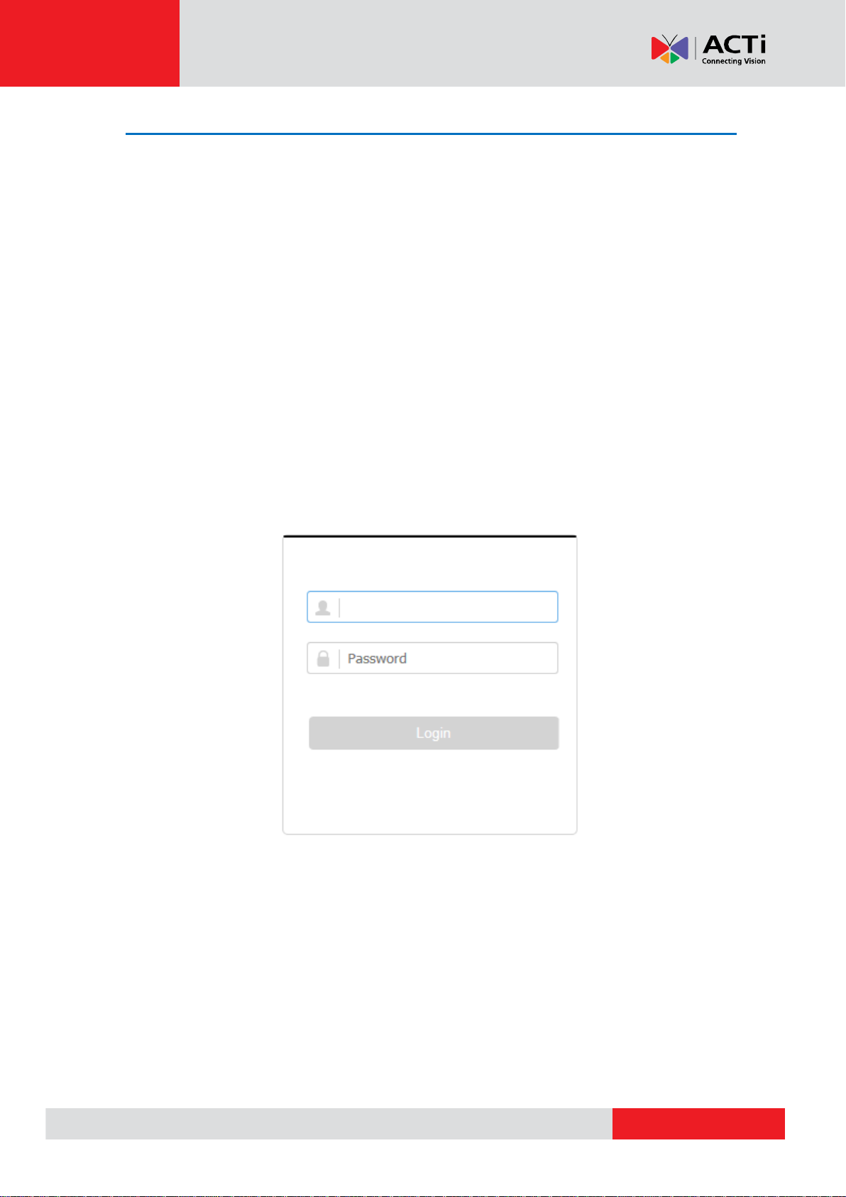
Access the Camera
Now that the camera and the PC are both having their unique IP addresses and are under the
same network segment, it is possible to use the Web browser of the PC to access the camera.
Open the web browser, input the IP address of the camera, and then press Enter to go to the
login page.
Assuming that the camera’s IP address is 192.168.0.100, type the following address into Web
browser’s address bar:
http://192.168.0.100
Upon successful connection to the camera, the user interface will appear together with the login
page.
Before logging in, the admin user should configure first the device account and password. This
account and password will be used for future administrator logins.
NOTE: You may be prompted to install the necessary plug-ins in before viewing the live video
and operating the camera. Follow the on-screen instructions to install plug-ins.
NOTE: The Admin user can set the login attmeps with the wrong password. When your login
attempts with the wrong password reach the set times, the device is locked. Go to Configuration
> System > Security > Security Service, and enable Enable Illegal Login lock, and set the
illegal login attempts.
13
Page 14

www.acti.com
VMGB-370 User’s Manual
Using IPv6 to Access the Camera
The camera is IPv6-ready. You need to configure this address in the Configuration page after
accessing the camera. The IPv6 address can be found under the Configuration > Network >
Basic Settings > TCP/IP menu.
14
Page 15

www.acti.com
VMGB-370 User’s Manual
Temperature Measurement
When you enable this function, the device measures the actual temperature of the scene. It
alarms when temperature exceeds the temperature threshold value.
Notice
This part introduces the notices of configuring temperature measurement function.
The target surface should be as vertical to the optical axis as possible. It is
recommended that the angle of oblique image plane should be less than 45°.
The target image pixels should be more than 5 × 5.
If multiple presets will be taken for temperature measurement, it is recommended to set
the patrol time above 20 s.
Please select line thermography or area thermography for a certain area temperature
measurement. The point thermography is not recommended in case of deviation
occurred during device movement to affect the accuracy of temperature measurement.
Automatic Thermography
Configure the temperature measurement parameters and temperature measurement rules. The
device can measure the actual temperature and output alarms when temperature exceeds the
alarm threshold value.
Set Thermography Parameters
Configure the parameters of temperature measurement.
Go to Configuration → System → Maintenance → VCA Resource Type, select Temperature
Measurement.
1. Go to Configuration → Local, enable Display Temperature Info.
Display Temperature Info.
Select Yes to display temperature information on live view.
Enable Rules to display the rules information on live view.
2. Click Save.
3. Go to Configuration → Temperature Measurement → Basic Settings to configure
parameters.
Enable Temperature Measurement
Check to enable temperature measurement function.
Enable Color-Temperature
Check to display Temperature-Color Ruler in live view.
Display Temperature Info. on Stream
Check to display temperature information on the stream.
15
Page 16

www.acti.com
VMGB-370 User’s Manual
Display Temperature in Optical Channel
Check to display thermal channel temperature information in the optical channel.
Display Max./Min./Average Temperature
Check to display maximum/minimum/average temperature information on liveview
when the temperature measurement rule is line or area.
Position of Thermometry Info
Select the position of temperature information showed on the live view.
Near Target: display the information beside the temperature measurement rule.
Top Left: display the information on the top left of screen.
Add Original Data on Capture
Check to add data on alarm triggered capture of thermal channel.
Add Original Data on Stream
Check to add original data on thermal view.
Data Refresh Interval
It means the refresh interval of temperature information.
Unit
Display temperature with Degree Celsius (°C)/Degree Fahrenheit (°F)/Degree Kelvin
(K).
Temperature Range
Select the temperature measurement range.
Version
View the version of current algorithm.
4. Click Save.
Set Normal Mode
This function is used to measure the temperature of the whole scene and alarm.
1. Go to Configuration → Temperature Measurement → Basic Settings, and check
Enable Temperature Measurement.
2. Refer to Set Thermography Parameters to set the parameters.
3. Go to Configuration → Temperature Measurement → Advanced Settings, and select
Normal.
4. Configure the parameters of normal mode.
Emissivity
Set the emissivity of your target. The emissivity of each object is different.
Distance
The distance between the target and the device.
Pre-Alarm Threshold
When the temperature of target exceeds the pre-alarm threshold, and this status
16
Page 17

www.acti.com
VMGB-370 User’s Manual
keeps more than Filtering Time, it triggers pre-alarm.
Alarm Threshold
When the temperature of target exceeds the alarm threshold, and this status keeps
more than Filtering Time, it triggers alarm.
Pre-Alarm Output and Alarm Output
Check Pre-Alarm Output and Alarm Output to link the pre-alarm or alarm with the
connected alarm device.
5. Refer to Set Arming Schedule for setting scheduled time. Refer to Linkage Method
Settings for setting linkage method.
6. Click Save.
The maximum and minimum temperature will be displayed on the live view.
NOTE:
Go to Image → VCA Rules Display to adjust the fonts size and the temperature colour of
normal, alarm and pre-alarm.
Set Expert Mode
Select the temperature measurement rules from Point, Line, or Area and configure parameters,
the device alarms if the alarm rules are met.
1. Go to Configuration → Temperature Measurement → Basic Settings, check Enable
Temperature Measurement.
2. Refer to Set Thermography Parameters to set the parameters.
3. Go to Configuration → Temperature Measurement → Advanced Settings, select
Expert.
4. Select and enable the temperature measurement rules. Please refer to Set
Thermography Rule for setting the rule.
5. Optional: Click Area's Temperature Comparison to set the alarm rules and the
temperature.
6. Refer to Set Arming Schedule for setting scheduled time. Refer to Linkage Method
Settings for setting linkage method.
7. Click Save.
The maximum temperature and thermography rules will be displayed on the liveview.
NOTE:
Go to Image → VCA Rules Display to adjust the fonts size and the temperature colour of normal, alarm
and pre-alarm.
17
Page 18

www.acti.com
VMGB-370 User’s Manual
Point
Please refer to Paint Thermography for detailed configuration.
Line
Please refer to Line Thermography for detailed configuration.
Area
Please refer to Area Thermography for detailed configuration.
Set Thermography Rule
1. Customize the rule name.
2. Select the rule type to Point, Line, or Area. Then draw a point, line, or area on the
interface where the position to be measured.
3. Configure the temperature measurement parameters.
Emissivity
Set the emissivity of the target. The emissivity of the surface of a material is its
effectiveness in emitting energy as thermal radiation. Different objects have different
emissivity. Refer to Common Material Emissivity Reference to search for the target
emissivity.
Distance
The distance between the target and the device.
Reflective Temperature
If there is any object with high emissivity in the scene, check and set the reflective
temperature to correct the temperature. The reflective temperature should be set the
same as the temperature of the high emissivity object.
4. Click and set the Alarm Rule.
Alarm Temperature and Pre-Alarm Temperature
Set the alarm temperature and pre-alarm temperature. E.g., select Alarm Rule as
Above (Average Temperature), set the Pre-Alarm Temperature to 50 °C, and set the
Alarm temperature to 55 °C. The device pre-alarms when its average temperature is
higher than 50 °C and alarms when its average temperature is higher than 55 °C.
Filtering Time
It refers to the duration time after the target temperature reaches or exceeds the
pre-alarm temperature/alarm temperature.
Tolerance Temperature
Set the tolerance temperature to prevent the constant temperature change to affect
the alarm. E.g., set tolerance temperature as 3°C, set alarm temperature as 55°C, and
set pre-alarm temperature as 50°C. The device sends pre-alarm when its temperature
reaches 50°C and it alarms when its temperature reaches 55°C and only when the
device temperature is lower than 52°C will the alarm be cancelled.
Pre-Alarm Output and Alarm Output
When the temperature of target exceeds the pre-alarm or alarm threshold, it triggers
the pre-alarm or alarm output of the connected device.
18
Page 19

www.acti.com
VMGB-370 User’s Manual
Area's Temperature Comparison
Select two areas and set the comparison rule, and set the temperature difference
threshold. The device alarms when the temperature difference meets the setting
value.
5. You can shield certain area from being detected. Refer to Set Shielded Region for
detailed settings.
6. Click Save.
Click Live View, and select thermal channel to view the temperature and rules
information on live view.
Point Thermography
Configure the temperature measurement rule and click any point in live view to monitor the
temperature.
1. Click in the live view and a cross cursor showed on the interface.
2. Drag the cross cursor to desired position.
Go to Live View interface to view the temperature and rule of the point in thermal
channel.
Line Thermography
Configure the temperature measurement rule and monitor the maximum temperature of the line.
1. Click and drag the mouse to draw a line in the live view interface.
2. Click and move the line to adjust the position.
3. Click and drag the ends of the line to adjust the length.
Go to Live View interface to view the maximum temperature and rule of the line in
thermal channel.
Area Thermography
Configure the temperature measurement rule and monitor the maximum temperature of the area.
1. Click and drag the mouse in the liveview to draw the area and right click to finish drawing.
2. Click and move the area to adjust the position.
3. Drag the corners of the area to adjust the size and shape.
Go to Live View interface to view the maximum temperature and rule of the area in
thermal channel.
Set Shielded Region
You can configure areas from being detected.
1. Check Enable Shield Area.
2. Click .
3. Drag the mouse in the live view to draw the area. You can drag the corners of the red
19
Page 20

www.acti.com
VMGB-370 User’s Manual
rectangle area to change its shape and size.
4. Right click the mouse to stop drawing.
5. Optional: Select one area and click to delete it.
6. Click Save.
Manual Thermography
After enable the manual thermography function of the device, you can click any position on the
live view to show the real temperature.
1. Go to Configuration → Local and select Display Temperature Info. as Yes.
2. Go to Configuration → Temperature Measurement → Basic Settings.
3. Check Enable Temperature Measurement.
4. Click Save.
5. Go to live view interface and select thermal channel, click . Click any position on the
interface to show the real temperature.
20
Page 21

www.acti.com
VMGB-370 User’s Manual
Measure Body Temperature
1. Go to Configuration Temperature Measurement Body Thermography
Configuration.
2. Select thermal channel.
3. Click Draw Area, then click the mouse on the black body in live view and save it.
4. Set the black body parameters.
Emissivity: Set the emissivity of black body.
NOTE:
Refer to the emissivity table for reference in the manual or online.
Distance: The straight-line distance between the black body and the device.
Temperature: Enter the temperature of the black body.
NOTE:
If there is no black body in the scene, skip step 3 and 4.
5. Set Environmental Temperature Mode. Auto and Manual are selectable. In auto mode,
the device detects environment temperature automatically. In manual mode, you should
enter environment temperature manually.
6. Set the body temperature compensation parameters if you need to detect human body
temperature instead of shell temperature.
i. Enable body temperature compensation function.
ii. Select the compensation type.
iii. In auto mode, the device calculates compensation value automatically. If the
detected body temperature is still inaccuracy, you can set Manual Calibration
value.
iv. In manual mode, you should enter Manual Calibration value, and corresponding
compensation value displays in Compensation Value field.
7. Click Save.
8. Set the arming schedule and linkage methods. For the information about arming
schedule settings, see Set Arming Schedule. For the information about linkage
methods, see Linkage Method Settings.
21
Page 22

www.acti.com
VMGB-370 User’s Manual
Body Thermography
Body Thermography function can detect temperature of human face or body in the scene, and
output alarm if the temperature is higher than the setting value.
Set Body Thermography Parameters
Configure the parameters of body temperature measurement. Go to Configuration → System →
Maintenance → VCA Resource Type, select Body Thermography.
1. Go to Configuration → Temperature Measurement → Basic Settings to configure
parameters.
Enable Temperature Measurement
Check to enable temperature measurement function.
Enable Color-Temperature
Check to display Temperature-Color Ruler in live view.
Display Temperature Info. on Stream
Check to display temperature information on the stream.
Add Original Data on Capture
Check to add data on alarm triggered capture of thermal channel.
Add Original Data on Stream
Check to add original data on thermal view.
Data Refresh Interval
It means the refresh interval of temperature information.
Unit
Display temperature with Degree Celsius (°C)/Degree Fahrenheit (°F)/Degree Kelvin
(K).
Temperature Range
Select the temperature measurement range.
Distance
Set the distance between device and the target.
Emissivity
Set the emissivity of your target.
NOTE:
Refer to the emissitivity table for reference in the manual.
22
Page 23

www.acti.com
VMGB-370 User’s Manual
Version
View the version of the current algorithm.
2. Click Save.
Set Body Thermography
Measured Body Temperature in Thermal Channel
1. Go to Configuration → Body Thermography → Body Thermography Configuration.
2. Select thermal channel.
3. Click Draw Area, then click the mouse on the black body in live view and save it.
4. Set the black body parameters.
Emissivity: Set the emissivity of black body.
NOTE: Refer to the emissivity table for reference in the manual or online.
Distance: The straight-line distance between the black body and the device.
Temperature: Enter the temperature of the black body.
5. Set Environmental Temperature Mode. Auto and Manual are selectable. In auto mode, the
device detects environment temperature automatically. In manual mode, you should enter
environment temperature manually.
6. Set the body temperature compensation parameters if you need to detect human body
temperature instead of shell temperature.
i. Enable body temperature compensation function.
ii. Select the compensation type.
iii. In auto mode, the device calculates compensation value automatically. If the detected
body temperature is still inaccuracy, you can set Manual Calibration value.
iv. In manual mode, you should enter Manual Calibration value, and corresponding
compensation value displays in Compensation Value field.
7. Click Save.
8. Set the arming schedule and linkage methods. For the information about arming schedule
settings, see Set Arming Schedule. For the information about linkage methods, see
Linkage Method Settings..
23
Page 24

www.acti.com
VMGB-370 User’s Manual
Measure Face Temperature in Optical Channel
1. Go to Configuration → Body Thermography → Body Thermography Configuration.
2. Select the optical channel.
3. Check Enable Face Detection to detect human faces, and measure the temperature in the
scene.
4. Check Display Temperature to display the highest temperature of each detected face in live
view.
5. Check Upload Captured Face Image to capture and upload the face image of the target. If
face detection function is also enabled, max. temperature of the face displays on the image.
NOTE: Refer to face capture section to set the corresponding parameters.
6. Check Display Face Temperature Position to show a cursor on the position of max.
temperature.
7. Select Configuration mode. Targeting refers to measure the temperatures for all the targets
in the scene, and output alarm if the target temperature is higher than the alarm threshold.
NOTE: If temperatures of multiple targets are higher than the alarm threshold, then multiple
alarms will be triggered.
8. Set the face detection parameters.
Pupil Distance: The pupil distance refers to the square size composed by the area
between two pupils, and it is the basic standard for a camera to identify a target. You can
enter the pupil distance value or draw pupil distance areas in live view.
Generation Speed: It refers to the target generation speed. The higher the value is, the
easier the target can be detected.
Sensitivity: It refers to face detection sensitivity.
Alarm When Temperature is Above: It refers to the temperature alarm threshold. When
the target temperature is higher than the setting value, the device outputs alarm.
Pre-Alarm Temperature: When the face temperature is higher than the set value, the
device outputs pre-alarm and upload captured face image.
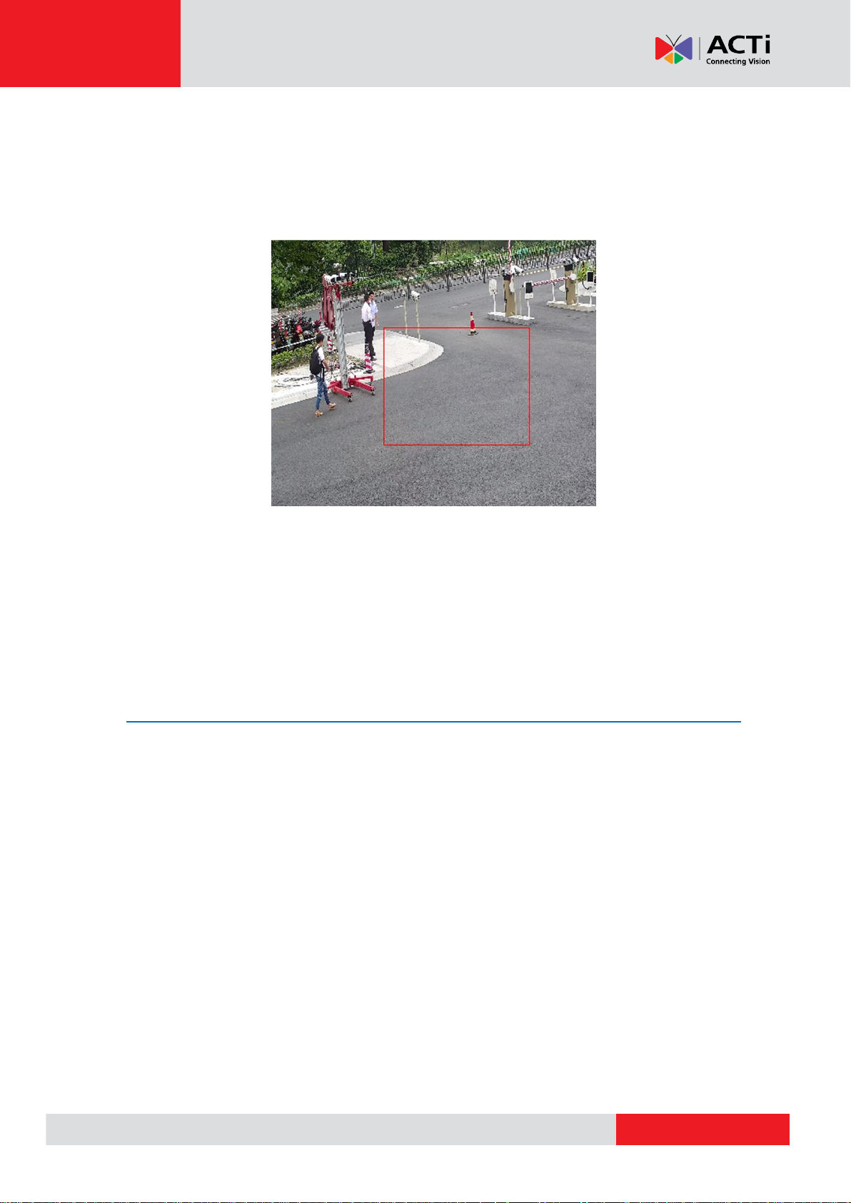
9. Click Draw Area, and draw a face detection area in live view. You can move the rectangle or
drag the corners of rectangle to adjust the position and size.
NOTE: You should draw the detection area within the red rectangle.
10. Click Save.
11. Set the arming schedule and linkage methods. For the information about arming schedule
settings, see Set Arming Schedule. For the information about linkage methods, see
Linkage Method Settings.
24
Page 25

www.acti.com
VMGB-370 User’s Manual
Set Face Capture
The camera can capture the face that appears in the configured area, and the face information
will be uploaded with the captured picture as well.
Overlay and Capture
1. Go to Configuration>Body Thermography >Face Capture >Overlay and Capture.
2. Check Display Target info. on Alarm Picture to show a frame on the target on the uploaded
alarm picture.
3. Set the target picture size. Four types are available: Custom, Head Shot, Half-Body Shot
and Full-Body Shot. If you select Custom, you can customized the width, head height and
body height as required.
4. Check Fixed Value to set the picture height.
5. Check the Background Upload to upload the background image.
6. Select the Picture Quality and Resolution from the drop-down list.
7. Click Save.
Set Shield Region
The shield region allows you to set the specific region in which the face capture does not work.
1. Click to draw shield area by left click end-points in the live view window, and right click to
finish the area drawing.
2. Optional: Click x to delete the drawn areas.
NOTE: You are allowed to draw up to 4 areas on the same image, and each area can be set
with 3-10 points.
3. Click Save.
Advanced Configuration
Face Capture Version: It lists the version of the algorithms library.
Upload Feature: Check to upload the feature of captured target.
Capture Times: Refers to the capture times a face will be captured during its stay in the
configured area.
Quick Shot: You can define quick shot threshold and max. capture interval.
o Quick Shot Threshold: It stands for the quality of face to trigger quick shot.
o Max. Capture Interval: It describes the max. time occupation for one quick shot.
No Wearing Mask Linkage: Check Audible Warning, the device will output audio alarm
if the target is not wearing mask.
25
Page 26

www.acti.com
VMGB-370 User’s Manual
Event and Alarm
This part introduces the configuration of events. The device takes certain response to triggered
alarm.
Set Motion Detection
It helps to detect the moving objects in the detection region and trigger the linkage actions.
1. Go to Configuration → Event → Basic Event → Motion Detection.
2. Select the channel No.
3. Check Enable Motion Detection.
4. Optional: Highlight to display the moving object in the image in green.
1) Check Enable Dynamic Analysis for Motion.
2) Go to Configuration → Local.
3) Set Rules to Enable.
5. Select Configuration Mode, and set rule region and rule parameters.
For the information about normal mode, see Normal Mode.
For the information about expert mode, see Expert Mode.
6. Set the arming schedule and linkage methods. For the information about arming
schedule settings, see Set Arming Schedule. For the information about linkage
methods, see Linkage Method Settings.
7. Click Save.
26
Page 27

www.acti.com
VMGB-370 User’s Manual
Stop Drawing
Stop drawing one area.
Clear All
Clear all the areas.
Normal Mode
You can set motion detection parameters according to the device default parameters.
1. Select normal mode in Configuration.
2. Set the sensitivity of normal mode. The higher the value of sensitivity is, the more
sensitive the motion detection is. If the sensitivity is set to 0, motion detection and
dynamic analysis do not take effect.
3. Click Draw Area. Click and drag the mouse on the live video, then release the mouse to
finfish drawing one area.
4. Optional: You can set the parameters of multiple areas by repeating the above steps.
Expert Mode
You can configure the motion detection parameters of day/night switch according to the actual
needs.
1. Select expert mode in Configuration.
2. Set parameters of expert mode.
Day/Night Switch
OFF: Day/night switch is disabled.
Day/Night Auto-Switch: The system switches day/night mode automatically according
to environment. It displays colored image at day and black and white image at night.
Day/Night Scheduled-Switch: The system switches day/night mode according to the
schedule. It switches to day mode during the set periods and switches to night mode
during the other periods.
27
Page 28
www.acti.com
VMGB-370 User’s Manual
Stop Drawing
Finish drawing one area.
Clear All
Delete all the areas.
Stop Drawing
Finish drawing.
Clear All
Delete all the drawn areas.
Sensitivity
The higher the value of sensitivity is, the more sensitive the motion detection is. If the
sensitivity is set to 0, motion detection and dynamic analysis do not take effect.
3. Select an Area and click Draw Area. Click and drag the mouse on the live video, then
release the mouse to finish drawing one area.
4. Optional: Repeat the above steps to set multiple areas.
Set Video Tampering Alarm
When the configured area is covered and cannot be monitored normally, the alarm is triggered
and the device takes certain alarm response actions.
1. Go to Configuration → Event → Basic Event → Video Tampering.
2. Select the channel number.
3. Check Enable.
4. Set the Sensitivity. The higher the value is, the easier to detect the area covering.
5. Click Draw Area and drag the mouse in the live view to draw the area.
28
Page 29

www.acti.com
VMGB-370 User’s Manual
6. Refer to Set Arming Schedule for setting scheduled time. Refer to Linkage Method
Settings for setting linkage method.
7. Click Save.
Set Alarm Input
Alarm signal from the external device triggers the corresponding actions of the current device.
Before You Start
Make sure the external alarm device is connected. See Quick Start Guide for cables connection.
Steps
1. Go to Configuration → Event → Basic Event → Alarm Input.
2. Check Enable Alarm Input Handing.
3. Select Alarm Input NO. and Alarm Type from the dropdown list. Edit the Alarm Name.
4. Refer to Set Arming Schedule for setting scheduled time. Refer to Linkage Method
Settings for setting linkage method.
5. Click Copy to... to copy the settings to other alarm input channels.
6. Click Save.
29
Page 30

www.acti.com
VMGB-370 User’s Manual
HDD Full
The HDD storage is full.
HDD Error
Error occurs in HDD.
Network Disconnected
The device is offline.
IP Address Conflicted
The IP address of current device is same as that of other
device in the network.
Illegal Login
Incorrect user name or password is entered.
Set Exception Alarm
Exception such as network disconnection can trigger the device to take corresponding action.
1. Go to Configuration → Event → Basic Event → Exception.
2. Select Exception Type.
3. Refer to Linkage Method Settings for setting linkage method.
4. Click Save.
Detect Audio Exception
Audio exception detection function detects the abnormal sound in the surveillance scene, such as
the sudden increase/decrease of the sound intensity, and some certain actions can be taken as
response.
1. Go to Configuration → Event → Smart Event → Audio Exception Detection.
2. Select one or several audio exception detection types.
Audio Loss Detection
Detect sudden loss of audio track.
Sudden Increase of Sound Intensity Detection
Detect sudden increase of sound intensity. Sensitivity and Sound Intensity
Threshold are configurable.
NOTE:
The lower the sensitivity is, the more significant the change should be to trigger the detection.
The sound intensity threshold refers to the sound intensity reference for the detection. It is
recommended to set as the average sound intensity in the environment. The louder the
environment sound, the higher the value should be. You can adjust it according to the real
environment.
Sudden Decrease of Sound Intensity Detection
Detect sudden decrease of sound intensity. Sensitivity is configurable.
30
Page 31

www.acti.com
VMGB-370 User’s Manual
3. Refer to Set Arming Schedule for setting scheduled time. Refer to Linkage Method
Settings for setting linkage methods.
4. Click Save.
NOTE:
The function varies according to different models.
31
Page 32

www.acti.com
VMGB-370 User’s Manual
Automatic Alarm
For the information about the configuration, see Automatic
Alarm.
Manual Alarm
For the information about the configuration, see Manual Alarm.
Arming Schedule and Alarm Linkage
Arming schedule is a customized time period in which the device performs certain tasks. Alarm
linkage is the response to the detected certain incident or target during the scheduled time.
Set Arming Schedule
Set the valid time of the device tasks.
1. Click Arming Schedule.
2. Drag the time bar to draw desired valid time.
NOTE:
Up to 8 periods can be configured for one day.
3. Adjust the time period.
Click on the selected time period, and enter the desired value. Click Save.
Click on the selected time period. Drag the both ends to adjust the time period.
Click on the selected time period, and drag it on the time bar.
4. Optional: Click Copy to... to copy the same settings to other days.
5. Click Save.
Linkage Method Settings
You can enable the linkage functions when an event or alarm occurs.
Trigger Alarm Output
If the device has been connected to an alarm output device, and the alarm output No. has been
configured, the device sends alarm information to the connected alarm output device when an
alarm is triggered.
Steps
1. Go to Configuration → Event → Basic Event → Alarm Output.
2. Set alarm output parameters.
3. Click Save.
32
Page 33

www.acti.com
VMGB-370 User’s Manual
Manual Alarm
You can trigger an alarm output manually.
1. Set the manual alarm parameters.
Alarm Output No.
Select the alarm output No. according to the alarm interface connected to the
external alarm device.
Alarm Name
Custom a name for the alarm output.
Delay
Select Manual.
2. Click Manual Alarm to enable manual alarm output.
3. Optional: Click Clear Alarm to disable manual alarm output.
Automatic Alarm
Set the automatic alarm parameters, then the device triggers an alarm output automatically in the
set arming schedule.
1. Set automatic alarm parameters.
Alarm Output No.
Select the alarm output No. according to the alarm interface connected to the external
alarm device.
Alarm Name
Custom a name for the alarm output.
Delay
It refers to the time duration that the alarm output remains after an alarm occurs.
2. Set the alarming schedule. For the information about the settings, see Set Arming
Schedule.
3. Click Copy to… to copy the parameters to other alarm output channels.
4. Click Save.
FTP/NAS/Memory Card Uploading
If you have enabled and configured the FTP/NAS/memory card uploading, the device sends the
alarm information to the FTP server, network attached storage and memory card when an alarm
is triggered.
Refer to Set FTP to set the FTP server.
Refer to Set NAS for NAS configuration.
Refer to Set Memory Card for memory card storage configuration.
33
Page 34

www.acti.com
VMGB-370 User’s Manual
Send Email
Check Send Email, and the device sends an email to the designated addresses with alarm
information when an alarm event is detected.
For email settings, refer to Set Email.
Set Email
When the email is configured and Send Email is enabled as a linkage method, the device sends
an email notification to all designated receivers if an alarm event is detected.
Set the DNS server before using the Email function. Go to Configuration → Network → Basic
Settings → TCP/IP for DNS settings.
1. Go to email settings page: Configuration → Network → Advanced Settings → Email.
2. Set email parameters.
1) Input the sender's email information, including the Sender's Address, SMTP
Server, and SMTP Port.
2) Optional: If your email server requires authentication, check Authentication and
input your user name and password to log in to the server.
3) Set the E-mail Encryption.
When you select SSL or TLS, and disable STARTTLS, emails are sent
after encrypted by SSL or TLS. The SMTP port should be set as 465.
When you select SSL or TLS and Enable STARTTLS, emails are sent
after encrypted by STARTTLS, and the SMTP port should be set as 25.
NOTE:
If you want to use STARTTLS, make sure that the protocol is supported by your email server. If
you check the Enable STARTTLS while the protocol is not supported by your email sever, your
email is sent with no encryption.
4) Optional: If you want to receive notification with alarm pictures, check Attached
Image. The notification email has 3 attached alarm pictures about the event with
configurable image capturing interval.
5) Input the receiver's information, including the receiver's name and address.
6) Click Test to see if the function is well configured.
3. Click Save.
Notify Surveillance Center
Check Notify Surveillance Center, the alarm information is uploaded to the surveillance center
when an alarm event is detected.
34
Page 35

www.acti.com
VMGB-370 User’s Manual
Trigger Recording
Check Trigger Recording, and the device records the video about the detected alarm event.
For device with more than one camera channels, you can set one or more channels to take
recordings if needed.
For recording settings, refer to Video Recording and Picture Capture
Set Audible Alarm Output
For device that supports audible warning as a linkage method, options are open to configure
audible alarm parameters.
NOTE:
The function is only supported by certain camera models.
1. Go to the setting page: Configuration → Event → Basic Event → Audible Alarm
Output.
2. Select desired alarm sound type and alarm times.
3. Set arming schedule for audible alarm. Refer to Set Arming Schedule
4. Click Save.
Set Flashing Alarm Light Output
1. Go to Configuration → Event → Basic Event → Flashing Alarm Light Output.
2. Set Flashing Duration, Flashing Frequency and Brightness.
Flashing Duration
The time period the flashing lasts when one alarm happens.
Flashing Frequency
The flashing speed of the light. High, Medium, and Low are selectable.
Brightness
The brightness of the light.
3. Edit the arming schedule.
4. Click Save.
NOTE:
Only certain camera models support the function.
35
Page 36

www.acti.com
VMGB-370 User’s Manual
Live View
This section introduces the live view parameters, function icons and transmission parameters
settings.
Live View Parameters
NOTE:
For multichannel devices, select the desired channel first before live view settings.
Window Division
refers to 1 × 1 window division.
refers to 2 × 2 window division.
refers to 3 × 3 window division.
refers to 4 × 4 window division.
Live View Stream Type
Select the live view stream type according to your needs. For the detailed information about the
stream type selection, refer to Stream Type.
Enable and Disable Live View
This function is used to quickly enable or disable live view of all channels.
Click to start live view of all channels.
Click to stop live view of all channels.
Start Digital Zoom
It helps to see a detailed information of any region in the image.
1. Click to enable the digital zoom.
2. In live view image, drag the mouse to select the desired region.
3. Click in the live view image to back to the original image.
View Previous/Next Page
When the number of channels surpasses that of live view window division, this function can
switch live view among multiple channels.
Click to switch live view among multiple channels.
Full Screen
This function is used to view the image in full screen mode.
Click to start full screen mode and press ESC button to exit.
36
Page 37

www.acti.com
VMGB-370 User’s Manual
Light
Click to turn on or turn off the illuminator.
Wiper
For the device that has a wiper, you can control the wiper via web browser.
Click on live view page. The wiper wipes the window one time.
Lens Initialization
Lens initialization is used on the device equipped with motorized lens. The function can reset lens
when long time zoom or focus results in blurred image. This function varies according to different
models.
Click to operate lens initialization.
Auxiliary Focus
Click to realize automatic focus. This function is subject to the actual device model.
Quick Set Live View
It offers a quick setup of PTZ, display settings, OSD, video/audio and VCA resource settings on
live view page.
1. Click to show quick setup page.
2. Set PTZ, display settings, OSD, video/audio and VCA resource parameters.
For PTZ settings, see Lens Parameters Adjustment .
For display settings, see Display Settings.
For OSD settings, see OSD.
For audio and video settings, see Video and Audio.
For VCA settings, see Fire Source Detection, Temperature Measurement, and Behavior
Analysis.
NOTE:
The function is only supported by certain models.
Lens Parameters Adjustment
It is used to adjust the lens focus, zoom and iris.
Zoom
Click , and the lens zooms in.
Click , and the lens zooms out.
Focus
Click , then the lens focuses far and the distant object gets clear.
Click , then the lens focuses near and the nearby object gets clear.
37
Page 38

www.acti.com
VMGB-370 User’s Manual
PTZ Speed
Slide to adjust the speed of the pan/tilt movement.
Iris
When the image is too dark, click to enlarge the iris.
When the image is too bright, click to stop down the iris.
Set Transmission Parameters
The live view image may be displayed abnormally according to the network conditions. In
different network environments, you can adjust the transmission parameters to solve the
problem.
1. Go to Configuration → Local.
2. Set the transmission parameters as required.
Protocol
TCP
TCP ensures complete delivery of streaming data and better video quality, yet
the real-time transmission will be affected. It is suitable for the stable network
environment.
UDP
UDP is suitable for the unstable network environment that does not demand high
video fluency.
MULTICAST
MULTICAST is suitable for the situation that there are multiple clients. You should
set the multicast address for them before selection.
NOTE:
For detailed information about multicast, refer to Multicast.
HTTP
HTTP is suitable for the situation that the third-party needs to get the stream from
the device.
Play Performance
Shortest Delay
The device takes the real-time video image as the priority over the video fluency.
Balanced
The device ensures both the real-time video image and the fluency.
Fluent
The device takes the video fluency as the priority over teal-time. In poor network
environment, the device cannot ensures video fluency even the fluency is enabled.
38
Page 39

www.acti.com
VMGB-370 User’s Manual
Custom
You can set the frame rate manually. In poor network environment, you can
reduce the frame rate to get a fluent live view. But the rule information may cannot
display.
Auto Start Live View
Yes means the live view is started automatically. It requires a high performance
monitoring device and a stable network environment.
No means the live view should be started manually.
3. Click OK.
39
Page 40

www.acti.com
VMGB-370 User’s Manual
Video and Audio
This section introduces the configuration of video and audio related parameters.
Video Settings
This part introduces the settings of video parameters, such as, stream type, video encoding, and
resolution.
Go to setting page: Configuration → Video/Audio → Video.
NOTE:
For device with multiple camera channels, select a channel before other settings.
Stream Type
For device supports more than one stream, you can specify parameters for each stream type.
Main Stream
The stream stands for the best stream performance the device supports. It usually offers the
best resolution and frame rate the device can do. But high resolution and frame rate usually
means larger storage space and higher bandwidth requirements in transmission.
Sub Stream
The stream usually offers comparatively low resolution options, which consumes less
bandwidth and storage space.
Other Streams
Steams other than the main stream and sub stream may also be offered for customized
usage.
Video Type
Select the content (video and audio) that should be contained in the stream.
Video
Only video content is contained in the stream.
Video & Audio
Video content and audio content are contained in the composite stream.
Resolution
Select video resolution according to actual needs. Higher resolution requires higher bandwidth
and storage.
40
Page 41

www.acti.com
VMGB-370 User’s Manual
Bitrate Type and Max. Bitrate
Constant Bitrate
It means that the stream is compressed and transmitted at a comparatively fixed bitrate.
The compression speed is fast, but mosaic may occur on the image.
Variable Bitrate
It means that the device automatically adjust the bitrate under the set Max. Bitrate. The
compression speed is slower than that of the constant bitrate. But it guarantees the image quality
of complex scenes.
Video Quality
When Bitrate Type is set as Variable, video quality is configurable. Select a video quality
according to actual needs. Note that higher video quality requires higher bandwidth.
Frame Rate
The frame rate is to describe the frequency at which the video stream is updated and it is
measured by frames per second (fps).
A higher frame rate is advantageous when there is movement in the video stream, as it maintains
image quality throughout. Note that higher frame rate requires higher bandwidth and larger
storage space.
Video Encoding
It stands for the compression standard the device adopts for video encoding.
NOTE:
Available compression standards vary according to device models.
H.264
H.264, also known as MPEG-4 Part 10, Advanced Video Coding, is a compression standard.
Without compressing image quality, it increases compression ratio and reduces the size of video
file than MJPEG or MPEG-4 Part 2.
H.265
H.265, also known as High Efficiency Video Coding (HEVC) and MPEG-H Part 2, is a
compression standard. In comparison to H.264, it offers better video compression at the same
resolution, frame rate and image quality.
MJPEG
Motion JPEG (M-JPEG or MJPEG) is a video compression format in which intraframe coding
technology is used. Images in a MJPEG format is compressed as individual JPEG images.
41
Page 42

www.acti.com
VMGB-370 User’s Manual
Profile
This function means that under the same bitrate, the more complex the profile is, the higher the
quality of the image is, and the requirement for network bandwidth is also higher.
I-Frame Interval
I-frame interval defines the number of frames between 2 I-frames.
In H.264 and H.265, an I-frame, or intra frame, is a self-contained frame that can be
independently decoded without any reference to other images. An I-frame consumes more bits
than other frames. Thus, video with more I-frames, in other words, smaller I-frame interval,
generates more steady and reliable data bits while requiring more storage space.
SVC
Scalable Video Coding (SVC) is the name for the Annex G extension of the H.264 or H.265 video
compression standard.
The objective of the SVC standardization has been to enable the encoding of a high-quality video
bitstream that contains one or more subset bitstreams that can themselves be decoded with a
complexity and reconstruction quality similar to that achieved using the existing H.264 or H.265
design with the same quantity of data as in the subset bitstream. The subset bitstream is derived
by dropping packets from the larger bitstream.
SVC enables forward compatibility for older hardware: the same bitstream can be consumed by
basic hardware which can only decode a low-resolution subset, while more advanced hardware
will be able decode high quality video stream.
Smoothing
It refers to the smoothness of the stream. The higher value of the smoothing is, the better fluency
of the stream will be, though, the video quality may not be so satisfactory. The lower value of the
smoothing is, the higher quality of the stream will be, though it may appear not fluent.
Display VCA Info
VCA information can be displayed by Player and Video.
Player
Player means the VCA info can be displayed by the dedicated player provided by the
manufacturer.
Video
Video means the VCA info can be displayed by any general video player.
42
Page 43

www.acti.com
VMGB-370 User’s Manual
LineIn
Set Audio Input to LineIn when the device connects to the audio input
device with the high output power, such as MP3, synthesizer or active
pickup.
MicIn
Set Audio Input to MicIn when the device connects to the audio input
device with the low output power, such as microphone or passive
pickup.
Audio Settings
It is a function to set audio parameters such as audio encoding, environment noise filtering.
Go to the audio settings page: Configuration → Video/Audio → Audio.
Audio Encoding
Select the audio encoding compression of the audio.
Audio Input
NOTE:
Connect the audio input device as required.
The audio input display varies with the device models.
Environmental Noise Filter
Set it as OFF or ON. When the function is enabled, the noise in the environment can be filtered to
some extent.
Two-way Audio
It is used to realize the two-way audio function between the monitoring center and the target in
the monitoring screen.
Make sure the audio input device (pick-up or microphone) and audio output device
(speaker) connected to the device is working properly. Refer to specifications of audio
input and output devices for device connection.
If the device has built-in microphone and speaker, two-way audio function can be
enabled directly.
1. Click Live View.
2. Click on the toolbar to enable two-way audio function of the camera.
3. Click and select , move the slider to adjust the volume.
4. Click , disable the two-way audio function.
43
Page 44

www.acti.com
VMGB-370 User’s Manual
Set ROI
ROI (Region of Interest) encoding helps to assigns more encoding resource to the region of
interest, thus to increase the quality of the ROI whereas the background information is less
focused.
Please check the video coding type. ROI is supported when the video coding type is H.264 or
H.265.
1. Go to Configuration → Video/Audio → ROI.
2. Check Enable.
3. Select the channel No. according to your need.
4. Select Stream Type.
5. Select Region No. in Fixed Region to draw ROI region.
1) Click Drawing.
2) Click and drag the mouse on the view screen to draw the fixed region.
3) Click Stop Drawing.
NOTE:
Select the fixed region that needs to be adjusted and drag the mouse to adjust its position.
6. Input the Region Name and ROI Level.
7. Click Save.
NOTE:
The higher the ROI level is, the clearer the image of the detected region is.
8. Optional: Select other region No. and repeat the above steps if you need to draw multiple
fixed regions.
44
Page 45

www.acti.com
VMGB-370 User’s Manual
Display Settings
It offers the parameter settings to adjust image features.
Go to Configuration → Image → Display Settings.
For device that supports multiple channels, display settings of each channel is required.
Click Default to restore settings.
Image Adjustment
By adjusting the Brightness, Saturation, Contrast and Sharpness, the image can be best
displayed.
Image Adjustment (Thermal Channel)
You can optimize the image display effect of thermal channel by setting background correction
and manual correction.
Background Correction
Fully cover the lens with an object of uniform temperature in front of the lens, such as foam
board or paperboard. When you click Correct, the device will take the uniform object as the
standard and optimize the image once.
Manual Correction
Click Correct to optimize the image once.
NOTE:
It is a normal phenomenon that short video freezing might occur during the process of
Background Correction and Manual Correction.
Thermal AGC Mode
Choose the AGC mode according to different scenes to balance and improve the image quality.
Histogram: Choose for scene with obvious WDR and high temperature difference, can
improve image contrast and enhance image. E.g. the scene contains both indoor and
outdoor scenes.
Linear: Choose for scene with low temperature difference and the target is not obvious,
can improve image contrast and enhance image. E.g. the bird in forest.
Self-Adaptive: Choose AGC mode automatically according to current scene.
45
Page 46

www.acti.com
VMGB-370 User’s Manual
Exposure Settings
Exposure is controlled by the combination of iris, shutter, and photo sensibility. You can adjust
image effect by setting exposure parameters.
In manual mode, you need to set Exposure Time, Gain and Slow Shutter.
Day/Night Switch
Day/Night Switch function can provide color images in the day mode and black/white images in
the night mode. Switch mode is configurable.
Day
The image is always in color.
Night
The image is always black/white
Auto
The camera switches between the day mode and the night mode according to the
illumination automatically.
Scheduled-Switch
Set the Start Time and the End Time to define the duration for day mode.
NOTE:
Day/Night Switch function varies according to models.
Set Supplement Light
1. Go to Configuration → Maintenance → System Service.
2. Check Enable Supplement Light.
3. Click Save.
4. Go to Configuration → Image → Display Settings → Day/Night Switch to set
supplement light parameters.
Smart Supplement Light
This feature uses smart image processing technology to reduce overexposure caused
by supplement light.
IR Light Mode
When the mode is set to Auto, the supplement light is automatically enabled or
disabled according to the image brightness.
Brightness Limit
Adjust the upper limit of IR light power.
46
Page 47

www.acti.com
VMGB-370 User’s Manual
BLC
If you focus on an object against strong backlight, the object will be too dark to be seen clearly.
BLC (backlight compensation) compensates light to the object in the front to make it clear. If BLC
mode is set as Custom, you can draw a red rectangle on the live view image as the BLC area.
WDR
The WDR (Wide Dynamic Range) function helps the camera provide clear images in environment
with strong illumination differences.
When there are both very bright and very dark areas simultaneously in the field of view, you can
enable the WDR function and set the level. WDR automatically balances the brightness level of
the whole image and provides clear images with more details.
NOTE:
When WDR is enabled, some other functions may be not supported. Refer to the actual interface
for details.
White Balance
White balance is the white rendition function of the camera. It is used to adjust the color
temperature according to the environment.
DNR
Digital Noise Reduction is used to reduce the image noise and improve the image quality.
Normal and Expert modes are selectable.
Normal
Set the DNR level to control the noise reduction degree. The higher level means stronger
reduction degree.
Expert
Set the DNR level for both space DNR and time DNR to control the noise reduction degree.
The higher level means stronger reduction degree.
Defog
You can enable the defog function when the environment is foggy and the image is misty. It
enhances the subtle details so that the image appears clearer.
Set Palette
You can select the palette mode to display the thermal grayscale image to colored image.
1. Go to Configuration → Image → Display Settings.
2. Select the thermal channel.
3. Select a palette mode in Image Enhancement according to your need.
The live view displays the image with palette.
47
Page 48

www.acti.com
VMGB-370 User’s Manual
Set Target Color
You can set the color of the targets in different temperature ranges to identify the target quickly.
1. Go to Configuration → Image → Display Settings.
2. Select the thermal channel.
3. Click Image Enhancement, select Palette as White Hot or Black Hot.
4. Set the temperature value and color of High Temperature, Interval Temperature, or
Low Temperature targets.
Above (be colored)
When the target of high temperature needs to be colored, you can set the high
temperature color. Target above the setting temperature will be displayed in setting color.
Between (be colored)
When the target of an interval temperature needs to be colored, you can set the
interval temperature color. Target between the minimum and the maximum temperatures
will be displayed in setting color.
Below (be colored)
When the target of low temperature needs to be colored, you can set the low
temperature color. Target below the setting temperature will be displayed in setting color.
5. Click Save.
48
Page 49

www.acti.com
VMGB-370 User’s Manual
DDE
Digital Detail Enhancement is used to adjust the details of the image. OFF and Normal modes
are selectable.
OFF
Disable this function.
Normal
Set the DDE level to control the details of the image. The higher the level is, the more
details shows, but the higher the noise is.
Brightness Sudden Change
When the brightness of target and the background is hugely different (the temperature difference
of target and background is huge), the system reduces the difference for viewing.
Enhance Regional Image
You can select the desired area of image to improve the coding quality. The regional image will be
more detailed and clear.
1. Go to Configuration → Image → Display Settings → Image Enhancement.
2. Select the area of regional image enhancement. You can select OFF to disable this
function, or select Custom Area to draw a desired area.
A red rectangle shows on the display, in which the image quality is improved.
Mirror
When the live view image is the reverse of the actual scene, this function helps to display the
image normally.
Select the mirror mode as needed.
NOTE:
The video recording will be shortly interrupted when the function is enabled.
Video Standard
Video standard is an ability of a video card or video display device that defines the amount of
colors that are shown and the resolution. The two most common video standard used are NTSC
and PAL. In NTSC, 30 frames are transmitted each second. Each frame is made up of 525
individual scan lines. In PAL, 25 frames are transmitted each second. Each frame is made up of
625 individual scan lines. Select video signal standard according to the video system in your
country.
49
Page 50

www.acti.com
VMGB-370 User’s Manual
Drag the corners of the area
Adjust the size of the area.
Drag the area
Adjust the position of the area.
Click Clear All
Clear all the areas you set.
Digital Zoom
You can zoom in the image
The larger the zoom size is, the more blurred the image is.
Scene Mode
There are several sets of image parameters predefined for different installation environments.
Select a scene according to the actual installation environment to speed up the display settings.
OSD
You can customize OSD (On-screen Display) information such as device name, time/date, font,
color, and text overlay displayed on video stream.
Go to OSD setting page: Configuration → Image → OSD Settings. Set the corresponding
parameters, and click Save to take effect.
Displayed Information
Set camera name, date, week, and their related display format.
Text Overlay
Set customized overlay text on image.
OSD Parameters
Set OSD parameters, such as Display Mode, OSD Size, and Font Color.
Set Privacy Mask
The function blocks certain areas in the live view to protect privacy. No matter how the device
moves, the blocked scene will never be seen.
1. Go to privacy mask setting page: Configuration → Image → Privacy Mask.
2. Select the channel No.
3. Check Enable Privacy Mask.
4. Click Draw Area. Drag the mouse in the live view to draw a closed area.
5. Click Stop Drawing.
6. Click Save.
NOTE:
Up to 4 areas are supported for setting.
50
Page 51

www.acti.com
VMGB-370 User’s Manual
Normal Mode
Disable picture in picture mode.
Overlay Mode
Enable picture in picture mode. You can overlay
the image of another channel in the current
channel.
Overlay Picture
Overlay a customized picture on live view.
The picture to overlay has to be in BMP format with 24-bit, and the maximum picture size is 128 ×
128 pixel.
1. Go to picture overlay setting page: Configuration → Image → Picture Overlay.
2. Select a channel to overlay picture.
3. Click Browse to select a picture, and click Upload.
The picture with a red rectangle will appear in live view after successfully uploading.
4. Check Enable Picture Overlay.
5. Drag the picture to adjust its position.
6. Click Save.
Set Manual DPC (Defective Pixel Correction)
If the amount of defective pixels in the image is comparatively small and accurate correction is
needed, you can correct these pixels manually.
1. Go to Configuration → Image → DPC.
2. Select the thermal channel.
3. Select manual mode.
4. Click the defective pixel on the image, then a cursor shows on the live view.
5. Click Up, Down, Left, Right to adjust the cursor position to the defective pixel position.
6. Click , then click to correct defective pixel.
NOTE:
If multiple defective pixels need to be corrected, click after locating a defective pixel. Then
after locating other pixels, click to correct them simultaneously.
7. Optional: Click to cancel defective pixel correction.
Set Picture in Picture
You can overlay the images of two channels and view the image of two channels at the same
time.
1. Select a channel number.
2. Select the picture in picture mode.
3. Click Save.
51
Page 52

www.acti.com
VMGB-370 User’s Manual
Video Recording and Picture Capture
This part introduces the operations of capturing video clips and snapshots, playback, and
downloading captured files.
Storage Settings
This part introduces the configuration of several common storage paths.
Set Memory Card
If you choose to store the files to memory card, make sure you insert and format the memory card
in advance.
Insert the memory card to the camera. For detailed installation, refer to Quick Start Guide of the
camera.
1. Go to storage management setting page: Configuration → Storage → Storage
Management → HDD Management.
2. Select the memory card, and click Format to start initializing the memory card.
The Status of memory card turns to Normal from Uninitialized, which means the memory
card can be used normally.
3. Optional: Define the Quota of the memory card. Input the quota percentage for different
contents according to your need.
4. Click Save.
Set NAS
Take network server as network disk to store the record files, captured images, etc.
Get the IP address of the network disk first.
1. Go to NAS setting page: Configuration → Storage → Storage Management → Net
HDD.
2. Click HDD No. Select Mounting Type and set parameters for the disk.
Server Address
The IP address of the network disk.
File Path
The saving path of network disk files.
User Name and Password
The user name and password of the net HDD.
3. Click Test to check whether the network disk is available.
4. Click Save.
52
Page 53

www.acti.com
VMGB-370 User’s Manual
Protocol Version
The protocol version of the cloud storage server.
Server IP
The IP address of the cloud storage server. It supports
IPv4 address.
Serve Port
The port of the cloud storage server. 6001 is the default
port and you are not recommended to edit it.
User Name and
Password
The user name and password of the cloud storage server.
Set FTP
You can configure the FTP server to save images which are captured by events or a timed
snapshot task.
Get the FTP server address first.
1. Go to Configuration → Network → Advanced Settings → FTP.
2. Configure FTP settings.
Server Address and Port
The FTP server address and corresponding port.
User Name and Password
The FTP user should have the permission to upload pictures.
If the FTP server supports picture uploading by anonymous users, you can check
Anonymous to hide your device information during uploading.
Directory Structure
The saving path of snapshots in the FTP server.
3. Click Upload Picture to enable uploading snapshots to the FTP server.
4. Click Test to verify the FTP server.
5. Click Save.
Set Cloud Storage
It helps to upload the captured pictures and data to the cloud. The platform requests picture
directly from the cloud for picture and analysis. The function is only supported by certain models.
Steps
Caution
If cloud storage is enabled, the pictures are stored in the cloud storage server preferentially.
1. Go to Configuration → Storage → Storage Management → Cloud Storage.
2. Check Enable Cloud Storage.
3. Set basic parameters.
53
Page 54

www.acti.com
VMGB-370 User’s Manual
Picture Storage Pool
ID
The ID of the picture storage region in the cloud storage
server. Make sure storage pool ID and the storage region
ID are the same.
4. Click Test to test the configured settings.
5. Click Save.
Video Recording
This part introduces the operations of manual and scheduled recording, playback, and
downloading recorded files.
Record Automatically
This function can record video automatically during configured time periods.
Select Trigger Recording in event settings for each record type except Continuous. See Event
and Alarm for details.
1. Go to Configuration → Storage → Schedule Settings → Record Schedule.
2. Select channel No.
3. Check Enable.
4. Select a record type.
NOTE:
The record type is vary according to different models.
Continuous
The video will be recorded continuously according to the schedule.
Motion
When motion detection is enabled and trigger recording is selected as linkage
method, object movement is recorded.
Alarm
When alarm input is enabled and trigger recording is selected as linkage method, the
video is recorded after receiving alarm signal from external alarm input device.
Motion | Alarm
Video is recorded when motion is detected or alarm signal is received from the
external alarm input device.
Motion & Alarm
Video is recorded only when motion is detected and alarm signal is received from the
external alarm input device.
Event
The video is recorded when configured event is detected.
5. Set schedule for the selected record type. Refer to Set Arming Schedule for the setting
operation.
54
Page 55

www.acti.com
VMGB-370 User’s Manual
6. Click Advanced to set the advanced settings.
Overwrite
Enable Overwrite to overwrite the video records when the storage space is full.
Otherwise the camera cannot record new videos.
Pre-record
The time period you set to record before the scheduled time.
Post-record
The time period you set to stop recording after the scheduled time.
Stream Type
Select the stream type for recording.
NOTE:
When you select the stream type with higher bitrate, the actual time of the pre-record and
post-record may be less than the set value.
7. Click Save.
Record Manually
1. Go to Configuration → Local.
2. Set the Record File Size and saving path to for recorded files.
3. Click Save.
4. Click to start recording. Click to stop recording.
Playback and Download Video
You can search, playback and download the videos stored in the local storage or network
storage.
1. Click Playback.
2. Select channel No.
3. Set search condition and click Search.
The matched video files showed on the timing bar.
4. Click to play the video files.
Click to clip video files.
Click to play video files in full screen. Press ESC to exit full screen.
NOTE:
Go to Configuration → Local, click Save clips to to change the saving path of clipped video
files.
5. Click on the playback interface to download files.
1) Set search condition and click Search.
2) Select the video files and then click Download.
55
Page 56

www.acti.com
VMGB-370 User’s Manual
NOTE:
Go to Configuration → Local, click Save downloaded files to to change the saving path of
downloaded video files.
Capture Configuration
The device can capture the pictures manually or automatically and save them in configured
saving path. You can view and download the snapshots.
Capture Automatically
This function can capture pictures automatically during configured time periods.
If event-triggered capture is required, you should configure related linkage methods in event
settings. Refer to Event and Alarm for event settings.
1. Go to Configuration → Storage → Schedule Settings → Capture → Capture
Parameters.
2. Set the capture type.
Timing
Capture a picture at the configured time interval.
Event-Triggered
Capture a picture when an event is triggered.
3. Set the Format, Resolution, Quality, Interval, and Capture Number.
4. Refer to Set Arming Schedule for configuring schedule time.
5. Click Save.
Capture Manually
1. Go to Configuration → Local.
2. Set the Image Format and saving path to for snapshots.
JPEG
The picture size of this format is comparatively small, which is better for network
transmission.
BMP
The picture is compressed with good quality.
3. Click Save.
4. Click near the live view or play back window to capture a picture manually.
56
Page 57

www.acti.com
VMGB-370 User’s Manual
View and Download Picture
You can search, view and download the pictures stored in the local storage or network storage.
1. Click Picture.
2. Select channel No.
3. Set search condition and click Search.
The matched pictures showed in the file list.
4. Select the pictures then click Download to download them.
NOTE:
Go to Configuration → Local, click Save snapshots when playback to change the saving path
of pictures.
57
Page 58

www.acti.com
VMGB-370 User’s Manual
Network Settings
TCP/IP
TCP/IP settings must be properly configured before you operate the device over network. IPv4
and IPv6 are both supported. Both versions can be configured simultaneously without conflicting
to each other.
Go to Configuration → Basic Configuration → Network → TCP/IP for parameter settings.
NIC Type
Select a NIC (Network Interface Card) type according to your network condition.
IPv4
Two IPv4 modes are available.
DHCP
The device automatically gets the IPv4 parameters from the network if you check
DHCP. The device IP address is changed after enabling the function. You can use SADP to
get the device IP address.
NOTE:
The network that the device is connected to should support DHCP (Dynamic Host Configuration
Protocol).
Manual
You can set the device IPv4 parameters manually. Input IPv4 Address, IPv4 Subnet
Mask, and IPv4 Default Gateway, and click Test to see if the IP address is available.
IPv6
Three IPv6 modes are available.
Route Advertisement
The IPv6 address is generated by combining the route advertisement and the device
Mac address.
NOTE:
Route advertisement mode requires the support from the router that the device is connected to.
DHCP
The IPv6 address is assigned by the server, router or gateway.
Manual
Input IPv6 Address, IPv6 Subnet, IPv6 Default Gateway. Consult the network
administrator for required information.
58
Page 59

www.acti.com
VMGB-370 User’s Manual
MTU
It stands for maximum transmission unit. It is the size of the largest protocol data unit that
can be communicated in a single network layer transaction.
The valid value range of MTU is 1280 to 1500.
DNS
It stands for domain name server. It is required if you need to visit the device with domain
name. And it is also required for some applications (e.g., sending email). Set Preferred DNS
Server and Alternate DNS server properly if needed.
Multicast Discovery
Check the Enable Multicast Discovery, and then the online network camera can be
automatically detected by client software via private multicast protocol in the LAN.
Port
The device port can be modified when the device cannot access the network due to port conflicts.
Caution
Do not modify the default port parameters at will, otherwise the device may be unaccessible.
Go to Configuration → Network → Basic Settings → Port for port settings.
HTTP Port
It refers to the port that access the device through the browser. You should enter the port No.
after the IP address. For example, when the HTTP port is modified to 81, you need to enter
http://192.168.0.100:81 in the browser for browser login.
HTTPS Port
It refers to the port of browser certificate access. Certificate verification is required when
accessing the device through the browser, and the security level is high.
RTSP Port
It refers to the port of real time streaming protocol.
Server Port
It refers to the port on which the client adds the device.
59
Page 60

www.acti.com
VMGB-370 User’s Manual
Auto Port Mapping
Refer to Set Auto Port Mapping for detailed information.
Manual Port Mapping
Refer to Set Manual Port Mapping for detailed information.
Port Mapping
By setting port mapping, you can access devices through the specified port.
When the ports in the device are the same as those of other devices in the network, refer to Port
to modify the device ports.
1. Go to Configuration → Network → Basic Settings → NAT.
2. Select the port mapping mode.
3. Click Save.
Set Auto Port Mapping
1. Check Enable UPnP™, and choose a friendly name for the camera, or you can use the
default name.
2. Select the port mapping mode to Auto.
3. Click Save.
NOTE:
UPnP™ function on the router should be enabled at the same time.
Set Manual Port Mapping
1. Check Enable UPnP™, and choose a friendly name for the device, or you can use the
default name.
2. Select the port mapping mode to Manual, and set the external port to be the same as the
internal port.
3. Click Save.
Go to the router port mapping settings interface and set the port number and IP address to be the
same as those on the device. For more information, refer to the router user manual.
60
Page 61

www.acti.com
VMGB-370 User’s Manual
Multicast
Multicast is group communication where data transmission is addressed to a group of destination
devices simultaneously. After setting multicast, you can send the source data efficiently to
multiple receivers.
Go to Configuration → Network → Basic Settings → Multicast for the multicast settings.
IP Address
It stands for the address of multicast host.
Stream Type
The stream type as the multicast source.
Video Port
The video port of the selected stream.
Audio Port
The audio port of the selected stream.
SNMP
You can set the SNMP network management protocol to get the alarm event and exception
messages in network transmission.
Before setting the SNMP, you should download the SNMP software and manage to receive the
device information via SNMP port.
1. Go to the settings page: Configuration → Network → Advanced Settings → SNMP.
2. Check Enable SNMPv1, Enable SNMP v2c or Enable SNMPv3.
NOTE:
The SNMP version you select should be the same as that of the SNMP software.
And you also need to use the different version according to the security level required. SNMP v1
is not secure and SNMP v2 requires password for access. And SNMP v3 provides encryption and
if you use the third version, HTTPS protocol must be enabled.
3. Configure the SNMP settings.
4. Click Save.
Access to Device via Domain Name
You can use the Dynamic DNS (DDNS) for network access. The dynamic IP address of the
device can be mapped to a domain name resolution server to realize the network access via
domain name.
Registration on the DDNS server is required before configuring the DDNS settings of the device.
1. Refer to TCP/IP to set DNS parameters.
2. Go to the DDNS settings page: Configuration → Network → Basic Settings → DDNS.
3. Check Enable DDNS and select DDNS type.
61
Page 62

www.acti.com
VMGB-370 User’s Manual
By Browsers
Enter the domain name in the browser address bar to access
the device.
By Client Software
Add domain name to the client software. Refer to the client
manual for specific adding methods.
By Browsers
Enter the WAN dynamic IP address in the browser
address bar to access the device.
By Client Software
Add the WAN dynamic IP address to the client
software. Refer to the client manual for details.
DynDNS
Dynamic DNS server is used for domain name resolution.
NO-IP
NO-IP server is used for domain name resolution.
4. Input the domain name information, and click Save.
5. Check the device ports and complete port mapping. Refer to Port to check the device
port , and refer to Port Mapping for port mapping settings.
6. Access the device.
Access to Device via PPPoE Dial Up Connection
This device supports the PPPoE auto dial-up function. The device gets a public IP address by
ADSL dial-up after the device is connected to a modem. You need to configure the PPPoE
parameters of the device.
1. Go to Configuration → Network → Basic Settings → PPPoE.
2. Check Enable PPPoE.
3. Set the PPPoE parameters.
Dynamic IP
After successful dial-up, the dynamic IP address of the WAN is displayed.
User Name
User name for dial-up network access.
Password
Password for dial-up network access.
Confirm
Input your dial-up password again.
4. Click Save.
5. Access the device.
62
Page 63

www.acti.com
VMGB-370 User’s Manual
Delete
Delete the selected ONVIF user.
Modify
Modify the selected ONVIF user.
NOTE:
The obtained IP address is dynamically assigned via PPPoE, so the IP address always changes
after rebooting the camera. To solve the inconvenience of the dynamic IP, you need to get a
domain name from the DDNS provider (e.g. DynDns.com). Refer to Access to Device via Domain
Name for detail information.
Set ONVIF
If you need to access to the device through ONVIF protocol, you can configure the ONVIF user to
enhance the network security.
1. Go to Configuration → Network → Advanced Settings → Integration Protocol.
2. Check Enable ONVIF.
3. Click Add to configure the ONVIF user.
4. Click Save.
5. Optional: Repeat the steps above to add more ONVIF users.
Set HTTP Listening
The device can send alarms to destination IP or host name through HTTP protocol. The
destination IP or host name should support the HTTP data transmission.
Steps
1. Go to Configuration → Network → Advanced Settings → HTTP Listening.
2. Input Destination IP or Host Name, URL, and Port.
3. Click Test.
NOTE:
Click Default to reset the destination IP or host name.
4. Click Save.
63
Page 64

www.acti.com
VMGB-370 User’s Manual
System and Security
It introduces system maintenance, system settings and security management, and explains how
to configure relevant parameters.
View Device Information
You can view device information, such as Device No., Model, Serial No. and Firmware Version.
Enter Configuration → System → System Settings → Basic Information to view the device
information.
Search and Manage Log
Log helps locate and troubleshoot problems.
1. Go to Configuration → System → Maintenance → Log.
2. Set search conditions Major Type, Minor Type, Start Time, and End Time.
3. Click Search.
The matched log files will be displayed on the log list.
4. Optional: Click Export to save the log files in your computer.
Import and Export Configuration File
It helps speed up batch configuration on other devices with the same parameters.
1. Export configuration file.
1) Go to Configuration → System → Maintenance → Upgrade & Maintenance.
2) Click Device Parameters and input the encryption password to export the
current configuration file.
3) Set the saving path to save the configuration file in local computer.
2. Import configuration file.
1) Access the device that needs to be configured via web browser.
2) Click Browse to select the saved configuration file.
3) Input the encryption password you have set when exporting the configuration
file.
4) Click Import.
64
Page 65

www.acti.com
VMGB-370 User’s Manual
Restore
Reset device parameters, except user information, IP
parameters and video format to the default settings.
Default
Reset all the parameters to the factory default.
NOTE:
Be careful when using this function. After resetting to the
factory default, all the parameters are reset to the default
settings.
Firmware
Locate the exact path of the upgrade file.
Firmware Directory
Locate the directory which the upgrade file belongs to.
Export Diagnose Information
Diagnose information includes running log, system information, hardware information.
Go to Configuration → System → Maintenance → Upgrade & Maintenance, and click
Diagnose Information to export diagnose information of the device.
Reboot
You can reboot the device via browser.
Go to Configuration → System → Maintenance → Upgrade & Maintenance, and click Reboot.
Restore and Default
Restore and Default helps restore the device parameters to the default settings.
1. Go to Configuration → System → Maintenance → Upgrade & Maintenance.
2. Click Restore or Default according to your needs.
Upgrade
You need to obtain the correct upgrade package.
Caution
DO NOT disconnect power during the process, and the device reboots automatically after
upgrade.
1. Go to Configuration → System → Maintenance → Upgrade & Maintenance.
2. Choose one method to upgrade.
3. Click Browse to select the upgrade file.
4. Click Upgrade.
65
Page 66

www.acti.com
VMGB-370 User’s Manual
View Open Source Software License
Go to Configuration → System → System Settings → About Device, and click View
Licenses.
Time and Date
You can configure time and date of the device by configuring time zone, time synchronization and
Daylight Saving Time (DST).
Synchronize Time Manually
1. Go to Configuration → System → System Settings → Time Settings.
2. Select Time Zone.
3. Click Manual Time Sync.
4. Choose one time synchronization method.
Select Set Time, and manually input or select date and time from the pop-up
calendar.
Check Sync. with computer time to synchronize the time of the device with that of the
local PC.
5. Click Save.
Set NTP Server
You can use NTP server when accurate and reliable time source is required.
Set up a NTP server or obtain NTP server information.
1. Go to Configuration → System → System Settings → Time Settings.
2. Select Time Zone.
3. Click NTP.
4. Set Server Address, NTP Port and Interval.
NOTE:
Server Address is NTP server IP address.
5. Click Test to test server connection.
6. Click Save.
Set DST
If the region where the device is located adopts Daylight Saving Time (DST), you can set this
function.
1. Go to Configuration → System → System Settings → DST.
2. Check Enable DST.
3. Select Start Time, End Time and DST Bias.
4. Click Save.
66
Page 67

www.acti.com
VMGB-370 User’s Manual
Set RS-232
RS-232 can be used to debug device or access peripheral device. RS-232 can allow
communication between the device and computer or terminal when the communication distance
is short.
Connect the device to computer or terminal with RS-232 cable.
1. Go to Configuration → System → System Settings → RS-232.
2. Set the RS-232 parameters to match the device with the computer or terminal.
3. Click Save.
Set RS-485
RS-485 is used to connect the device to external device. You can use RS-485 to transmit the data
between the device and the computer or terminal when the communication distance is too long.
Connect the device and computer or termial with RS-485 cable.
1. Go to Configuration → System → System Settings → RS-485.
2. Set the RS-485 parameters.
NOTE:
You should keep the parameters of the device and the computer or terminal all the same.
3. Click Save.
Set Same Unit
Set the same temperature unit and distance unit. When you enable this function, the unit cannot
be configured separately in other setting pages
1. Go to Configuration → System → System Settings → Unit Settings.
3. Check Use Same Unit.
4. Set the temperature unit and distance unit.
5. Click Save.
67
Page 68

www.acti.com
VMGB-370 User’s Manual
Security
You can improve system security by setting security parameters.
Authentication
You can improve network access security by setting RTSP and WEB authentication.
Go to Configuration → System → Security → Authentication to choose authentication protocol
and method according to your needs.
RTSP Authentication
Digest and digest/basic are supported, which means authentication information is needed
when RTSP request is sent to the device. If you select digest/basic, it means the device supports
digest or basic authentication. If you select digest, the device only supports digest authentication.
RTSP Digest Algorithm
MD5, SHA256 and MD5/SHA256 encrypted algorithm in RTSP authentication. If you enable
the digest algorithm except for MD5, the third-party platform might not be able to log in to the
device or enable live view because of compatibility. The encrypted algorithm with high strength is
recommended.
WEB Authentication
Digest and digest/basic are supported, which means authentication information is needed
when WEB request is sent to the device. If you select digest/basic, it means the device supports
digest or basic authentication. If you select digest, the device only supports digest authentication.
WEB Digest Algorithm
MD5, SHA256 and MD5/SHA256 encrypted algorithm in WEB authentication. If you enable
the digest algorithm except for MD5, the third-party platform might not be able to log in to the
device or enable live view because of compatibility. The encrypted algorithm with high strength is
recommended.
NOTE:
Refer to the specific content of protocol to view authentication requirements.
68
Page 69

www.acti.com
VMGB-370 User’s Manual
Forbidden
IP addresses in the list cannot access the device.
Allowed
Only IP addresses in the list can access the device.
Add
Add a new IP address to the list.
Modify
Modify the selected IP address in the list.
Delete
Delete the selected IP address in the list.
Security Audit Log
The security audit logs refer to the security operation logs. You can search and analyze the
security log files of the device so as to find out the illegal intrusion and troubleshoot the security
events.
Security audit logs can be saved on device internal storage. The log will be saved every half hour
after device booting. Due to limited storage space, you can also save the logs on a log server.
Search Security Audit Logs
You can search and analyze the security log files of the device so as to find out the illegal
intrusion and troubleshoot the security events.
NOTE: This function is only supported by certain camera models.
1. Go to Configuration → System → Maintenance → Security Audit Log.
2. Select log types, Start Time, and End Time.
3. Click Search.
The log files that match the search conditions will be displayed on the Log List.
4. Optional: Click Export to save the log files to your computer.
Set IP Address Filter
IP address filter is a tool for access control. You can enable the IP address filter to allow or forbid
the visits from the certain IP addresses.
IP address refers to IPv4.
1. Go to Configuration → System → Security → IP Address Filter.
2. Check Enable IP Address Filter.
3. Select the type of IP address filter.
4. Edit the IP address filter list.
5. Click Save.
69
Page 70

www.acti.com
VMGB-370 User’s Manual
Create and install
self-signed certificate
Refer to Create and Install Self-signed Certificate
Create certificate request
and install certificate
Refer to Install Authorized Certificate
Set SSH
SSH is a protocol to ensure security of remote login. This setting is reserved for professional
maintenance personnel only.
1. Go to Configuration → System → Security → Security Service.
2. Check Enable SSH.
3. Click Save.
Set HTTPS
HTTPS is a network protocol that enables encrypted transmission and identity authentication,
which improves the security of remote access.
1. Go to Configuration → Network → Advanced Settings → HTTPS.
2. Check Enable.
3. Click Delete to recreate and install certificate.
4. Click Save.
Create and Install Self-signed Certificate
1. Check Create Self-signed Certificate.
2. Click Create.
3. Follow the prompt to enter Country, Hostname/IP, Validity and other parameters.
4. Click OK.
The device will install the self-signed certificate by default.
Install Authorized Certificate
If the demand for external access security is high, you can create and install authorized certificate
via HTTPS protocol to ensure the data transmission security.
1. Select Create certificate request first and continue the installation.
2. Click Create.
3. Follow the prompt to input Country, Hostname/IP, Validity and other parameters.
4. Click Download to download the certificate request and submit it to the trusted authority
for signature.
5. Import certificate to the device.
1. Select Signed certificate is available, start the installation directly. Click Browse and
Install to import the certificate to the device.
70
Page 71

www.acti.com
VMGB-370 User’s Manual
2. Select Create the certificate request first and continue the installation. Click Browse and
Install to import the certificate to the device.
6. Click Save.
Set QoS
QoS (Quality of Service) can help improve the network delay and network congestion by setting
the priority of data sending.
NOTE:
QoS needs support from network device such as router and switch.
1. Go to Configuration → Network → Advanced Configuration → QoS.
2. Set Video/Audio DSCP, Alarm DSCP and Management DSCP.
NOTE:
Network can identify the priority of data transmission. The bigger the DSCP value is, the higher
the priority is. You need to set the same value in router while configuration.
3. Click Save.
Set IEEE 802.1X
You can authenticate user permission of the connected device by setting IEEE 802.1X.
Go to Configuration → Network → Advanced Settings → 802.1X, and enable the function.
Select protocol and version according to router information. User name and password of server
are required.
71
Page 72

www.acti.com
VMGB-370 User’s Manual
Modify
Select a user and click Modify to change the password
and permission.
Delete
Select a user and click Delete.
User and Account
Set User Account and Permission
The administrator can add, modify, or delete other accounts, and grant different permission to
different user levels.
Caution
To increase security of using the device on the network, please change the password of your
account regularly. Changing the password every 3 months is recommended. If the device is used
in high-risk environment, it is recommended that the password should be changed every month
or week.
1. Go to Configuration → System → User Management → User Management.
2. Click Add. Enter User Name, select Level, and enter Password. Assign remote
permission to users based on needs.
Administrator
The administrator has the authority to all operations and can add users and
operators and assign permission.
User
Users can be assigned permission of viewing live video, setting PTZ parameters,
and changing their own passwords, but no permission for other operations.
Operator
Operators can be assigned all permission except for operations on the
administrator and creating accounts.
NOTE:
The administrator can add up to 31 user accounts.
3. Click OK.
72
Page 73

www.acti.com
VMGB-370 User’s Manual
Material
Emissivity
Human Skin
0.98
Printed Curcuit Board
0.91
Concrete
0.95
Ceramic
0.92
Rubber
0.95
Paint
0.93
Wood
0.85
Pitch
0.96
Brick
0.95
Sand
0.90
Soil
0.92
Cloth
0.98
Hard Paperboard
0.90
White Paper
0.90
Water
0.96
Appendix
Common Material Emissivity Reference
73
Page 74

Copyright © 2020, ACTi Corporation All Rights Reserved
7F, No. 1, Alley 20, Lane 407, Sec. 2, Ti-Ding Blvd., Neihu District, Taipei, Taiwan 114, R.O.C.
TEL : +886-2-2656-2588 FAX : +886-2-2656-2599
Email: sales@acti.com
 Loading...