

Page 1

Utility
Snapshot Utility
V2.1
User’s Manual
Page 2

Page 3

i
Table of Contents
INTRODUCTION .................................................................................................................................. 3
F
UNCTIONALITY ................................................................................................................................... 3
NAPSHOT UTILITY POSITIONING ........................................................................................................ 3
S
NAPSHOT UTILITY POSITIONING ........................................................................................................ 4
S
SETUP
TEP1.SELECT A CHANNEL ID ............................................................................................................ 5
S
TEP2.SELECT SOURCE ..................................................................................................................... 6
S
Select IP Camera Source
Select NVR Source
TEP3.SETUP PROCESS ..................................................................................................................... 8
S
Snapshot Configuration
On Screen Display Configuration
Image File Name Format Configuration
TEP4.SETUP SCHEDULE ................................................................................................................... 9
S
TEP5.SETUP UPLAOD MODE .......................................................................................................... 10
S
Save to Local Drive
Upload to FTP
Send Mail
TEP6.START SNAPSHOT ................................................................................................................. 13
S
STATUS
..................................................................................................................................................... 5
................................................................................................................ 6
.......................................................................................................................... 7
.................................................................................................................. 8
................................................................................................... 8
........................................................................................ 9
....................................................................................................................... 10
.............................................................................................................................. 11
...................................................................................................................................... 12
................................................................................................................................................ 14
C
HANNEL STATUS ............................................................................................................................. 14
Page 4

ii
Table of Figures
FIGURE 1 ................................................................................................................................................... 5
IGURE 2 ................................................................................................................................................... 6
F
IGURE 3 ................................................................................................................................................... 7
F
IGURE 4 ................................................................................................................................................... 8
F
IGURE 5 ................................................................................................................................................... 9
F
IGURE 6 ................................................................................................................................................. 10
F
IGURE 7 ................................................................................................................................................. 11
F
IGURE 8 ................................................................................................................................................. 12
F
IGURE 9 ................................................................................................................................................. 13
F
Page 5
3
Introduction
Functionality
• Snapshots
• Send to FTP
• Serve multiple access
• Application Type
– Internet Viewing
– Mobile Phone Viewing
• Mo-soft Soft ware on Nokia, Sony Ericsson
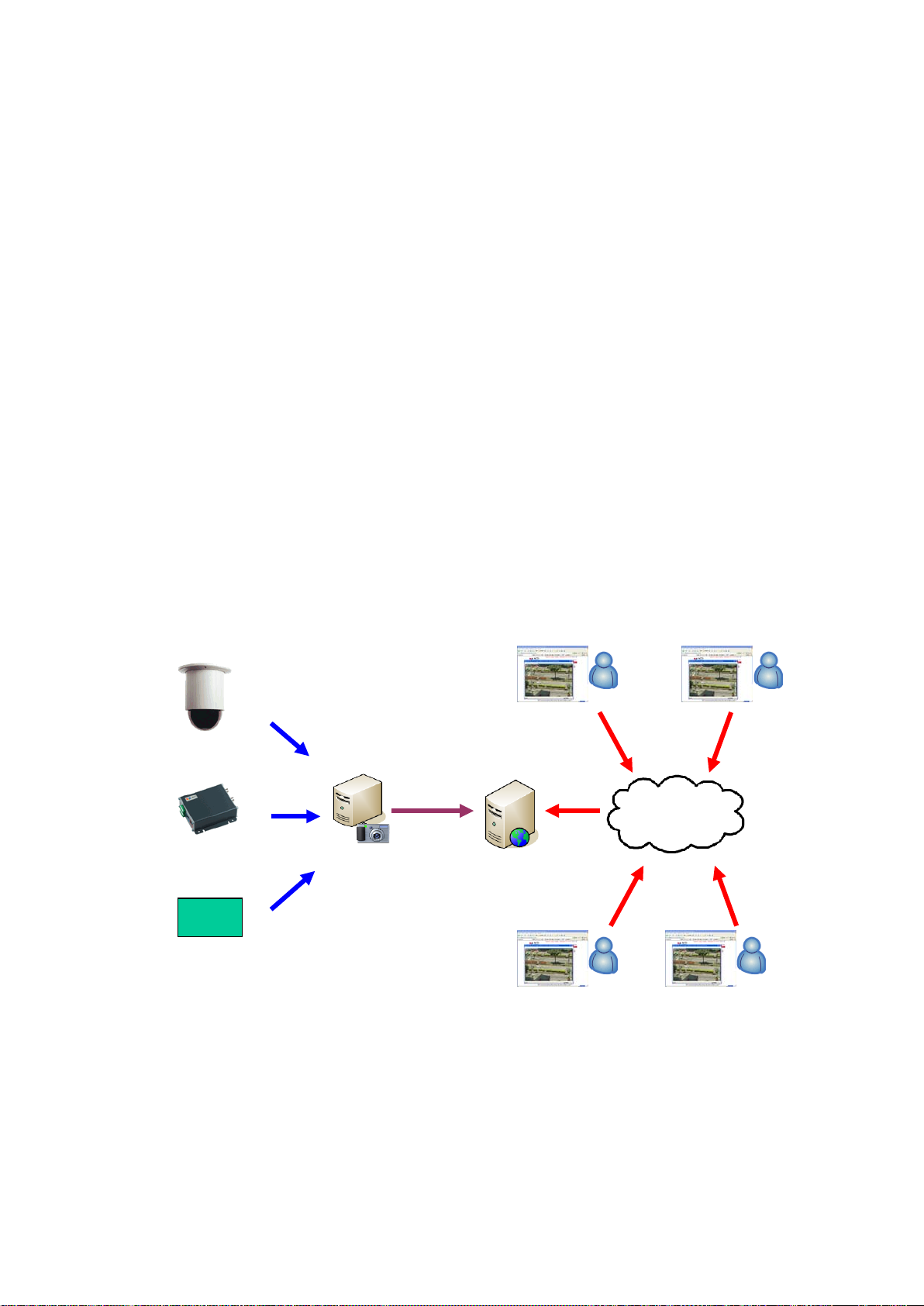
Snapshot Utility Positioning
IP Speed Dome
FTP
Snapshot
NVR
Web Server
Page 6

4
Snapshot
Snapshot Utility Positioning
IP Speed Dome
FTP
WAP Server
Page 7

5
Setup
Step1.Sele ct a Channel ID
Figure 1
Select a Channel ID to setup all configuration in snapshot utility
It will show description and Source in drop down list.
Page 8

6
Step2.Select Source
Select IP Camera Source
Figure 2
1. Select IP Camera option in source item.
2. Fil l in IP Address of camera or vi deo server .
3. Fill in Video Server HTTP port.
4. Fill in Video Server Video port.
5. Fill in Stream ID
6. Fill in Channel Number
7. Click Preview button to see if it can connect to camera.
Page 9

7
Select NVR Sourc e
Figure 3
1. Fill in NVR IP Address, Username, Password and HTTP Port.
2. Click “Get Camer a List” Button to get camera list in NVR Server .
3. Select a camera from NVR Server in drop down list.
4. Column of camera setting will be locked to prevent from being modified.
5. If Save this se t t ing as default checkbox i s checked, NVR IP Address,
NVR U sername, NVR Password, NVR HTTP p o rt, NVR Camera List data will be
saved as default.
Page 10

8
Step3.Setup Process
Figure 4
Snapshot Configuration
There are four options to set your snapshot rule.
1. Use FPS from camera will capture pictures per second as FPS setting.
2. When motion trigger in NVR, snapshot utility will capture picture and upload file as
your setting
3. When DI trigger in NVR, snapshot utility will capture picture and upload file as your
setting
4. Fill the interval of capture image from camera.
Except snapshot rule, you also can resize your snapshot image to 160X112 QCIF,
352x 24 0 CIF, 640x480 VGA, 720x480 Full D1 and 1280x1024 SXGA
On Screen Display Configuration
1 Check the item to show on frame.
1.1 Camera Name
1.2 Camera IP Address
1.3 Date
1.4 Time
Page 11

9
Image File Name Format Configuration
Select the file name format.
1. Default will be Channel<ID>.jpg
2. Channel<ID>_<Date>_<Time>.jpg
3. User defined text
Note: if you select Channel<ID> or user defined text as the snapshot file name, it will
replace the old one
Step4.Setup Schedule
Figure 5
1 Schedule setting
1.1 Select run process by schedule setting or always.
1.1.1 Always: User can set the schedule setting to always in date or time
1.1.2 By schedule: User can set the schedule setting by user defined date or
time
1.2 If run by schedule, setup schedule in the columns.
Page 12

10
Step5.Setup Uplaod Mode
After snapshot, system can select upload mode to dispatch th e snap s ho t file t o u se r, or
storage.
The upload mode includes:
1. Save to Lo cal Driv e
2. FTP
3. Send by em ail
Save to Local Drive
Figure 6
1. Browse a existing folder to save file.
Page 13

11
Upload to FTP
Figure 7
1 Fill in FTP login information.
1.1 FTP server: Fill with FTP server IP address or domain name
1.2 Login information:
1.2.1 User n ame and password
1.2.2 FTP port
2 Fill in a path on FTP to upload.
2.1 For example “\Snapshot\Camera1”
3 You can check the box “Delete file after upload successful” to delete file from
local drive after upload successfully.
Page 14

12
Send Mail
Figure 8
1 Fill in SMTP server login information.
3.1 SMTP server: Fill with SMTP server IP address or domain name
3.2 Login information:
3.2.1 Username and password: If need to authenticate before send mail, fill in
SMTP username, password.
3.2.2 SMTP po rt
2 Fill in Mail fro m, Mail to, Ma il CC and subject.
3 If there are more than 1 reveiver, split e-mail ac co un t b y “;”
3.1 Example:
4 You can check the box “Delete file after upload successful” to delete file from
local drive after upload successfully.
user1@yahoo.com;user2@msn.com;
 Loading...